ISHIDA BC-3000 Scale to Scale Communications - Rice Lake ...
ISHIDA BC-3000 Scale to Scale Communications - Rice Lake ...
ISHIDA BC-3000 Scale to Scale Communications - Rice Lake ...
You also want an ePaper? Increase the reach of your titles
YUMPU automatically turns print PDFs into web optimized ePapers that Google loves.
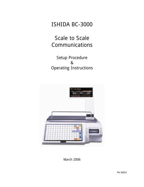
<strong>ISHIDA</strong> <strong>BC</strong>-<strong>3000</strong><strong>Scale</strong> <strong>to</strong> <strong>Scale</strong><strong>Communications</strong>Setup Procedure&Operating InstructionsMarch 2006PN 94561
Revision His<strong>to</strong>ryDate Page DescriptionMarch 2006Initial publicationAugust 2006 2 Added RS-232 cable information
<strong>BC</strong>-<strong>3000</strong> <strong>Scale</strong> <strong>to</strong> <strong>Scale</strong> <strong>Communications</strong>Overview..........................................................................................................................................2Communication Cables ....................................................................................................................2<strong>Scale</strong> <strong>to</strong> <strong>Scale</strong> .............................................................................................................................2<strong>Scale</strong> <strong>to</strong> PC (RS-232)...................................................................................................................2<strong>Scale</strong> <strong>to</strong> <strong>Scale</strong> <strong>Communications</strong> with a Master Board ...................................................................3System Configuration ......................................................................................................................3Additional Components....................................................................................................................3Firmware........................................................................................................................................3Installing the Master Board (P-835) in<strong>to</strong> a <strong>BC</strong>-<strong>3000</strong> Master <strong>Scale</strong> .......................................................4Master Board Kit Components (Part No 48744 or 48745) ...............................................................4Procedure...................................................................................................................................4Configuration Programming .............................................................................................................6Test Mode ..................................................................................................................................6Programming Mode.....................................................................................................................8Communication Settings ..................................................................................................................9Label Formats.................................................................................................................................9Chinese (Hong Kong) firmware (version C1312x) - Special RAM Clear...............................................10Background ..............................................................................................................................10Procedure.................................................................................................................................10Notes .......................................................................................................................................10<strong>Scale</strong> <strong>to</strong> <strong>Scale</strong> <strong>Communications</strong> without a Master Board............................................................11Overview ......................................................................................................................................11Configuration................................................................................................................................11Communication Cable....................................................................................................................12Programming................................................................................................................................12Operation .....................................................................................................................................12Totals...........................................................................................................................................12Errors...........................................................................................................................................12Label Formats...............................................................................................................................12Miscellaneous ...............................................................................................................................12Rev 2, August 2006 1 <strong>BC</strong>-<strong>3000</strong>_<strong>Scale</strong><strong>to</strong><strong>Scale</strong>_Comms
<strong>BC</strong>-<strong>3000</strong> <strong>Scale</strong> <strong>to</strong> <strong>Scale</strong> <strong>Communications</strong>OverviewThere are two methods available <strong>to</strong> interconnect the Ishida <strong>BC</strong>-<strong>3000</strong> printing scales with important differencesbetween the two. This document provides details <strong>to</strong> setup each of these two <strong>BC</strong>-<strong>3000</strong> scale <strong>to</strong> scalenetworks.The original method allows up <strong>to</strong> five <strong>BC</strong>-<strong>3000</strong> scales <strong>to</strong> be connected. These scales only communicateduring PLU programming and price changes. Note that <strong>Scale</strong> #1 does not support PC communications as par<strong>to</strong>f the system. PLU and price changes must be programmed at <strong>Scale</strong> #1. In this document this system isreferred <strong>to</strong> as a "No Master Board" system.The new <strong>BC</strong>-<strong>3000</strong> scale network utilizes a Master board which provides on-line communication between theMaster and Satellite scales. Up <strong>to</strong> 30 Satellite scales can be connected <strong>to</strong> the Master scale. The Master boardallows communication <strong>to</strong> the Satellite scales as well as a PC. This system is referred <strong>to</strong> as "With MasterBoard". Refer <strong>to</strong> Table 1 below for a summary of each system.Feature With Master Board No Master BoardMaximum number of scales 31 5PC <strong>Communications</strong> Yes NoCommunication Method On-Line Download during programmingEthernet communications Optional, Master scale only Not availableTable 1. Comparison of <strong>BC</strong>-<strong>3000</strong> <strong>Scale</strong> SystemsCommunication Cables<strong>Scale</strong> <strong>to</strong> <strong>Scale</strong>A shielded 4-conduc<strong>to</strong>r twisted-pair cable is used <strong>to</strong> inter-connect the scales for both <strong>BC</strong>-<strong>3000</strong> system types.The cable is terminated at a 9-Pin Sub-Miniature D-Type male connec<strong>to</strong>r. Grounding, if available, is made a<strong>to</strong>nly one point - the chassis of the Master scale (<strong>Scale</strong> #1). At the other scales the ground wires are "daisychained" between the cables without connection <strong>to</strong> the scales. The ground cable at the last scale is not used.Cable Pinout (straight through configuration)Pair OnePair Two5 ----- 5 Data9 ----- 9 Data3 ----- 3 Signal Ground7 ----- 7 Frame Ground<strong>Scale</strong> <strong>to</strong> PC (RS-232)A communication grade cable is required <strong>to</strong> connect a <strong>BC</strong>-<strong>3000</strong> Master <strong>Scale</strong> <strong>to</strong> a PC. The pinout of therequired standard, straight-through RS-232 cable is shown below.PC (9 pin) [female]<strong>Scale</strong> (25 pin) [male]1 8 (DCD)2 3 (Rx)3 2 (Tx)4 20 (DTR)5 7 (Signal Ground)6 6 (DSR)7 4 (RTS)8 5 (CTS)9 22 (RI)Note: The mounting terminals for the I2NET and RS-232 connections are metric. The screws supplied withstandard US DB9 and DB25 connec<strong>to</strong>rs should be replaced with the following metric screws:2.5mm x 12mm screws.Rev 2, August 2006 2 <strong>BC</strong>-<strong>3000</strong>_<strong>Scale</strong><strong>to</strong><strong>Scale</strong>_Comms
<strong>BC</strong>-<strong>3000</strong> <strong>Scale</strong> <strong>to</strong> <strong>Scale</strong> <strong>Communications</strong><strong>Scale</strong> <strong>to</strong> <strong>Scale</strong> <strong>Communications</strong> with a Master BoardFigure 1. <strong>BC</strong>-<strong>3000</strong> Master - Satellite SystemSystem Configuration• The <strong>BC</strong>-<strong>3000</strong> on-line scale system allows connection of up <strong>to</strong> thirty-one (31) <strong>BC</strong>-<strong>3000</strong> scales in onesystem.• For this system a P-835 Master board must be installed in the Master scale. Please refer <strong>to</strong> section"Installing the Master Board (P-835) in<strong>to</strong> a <strong>BC</strong>-<strong>3000</strong> Master <strong>Scale</strong>" for instructions.• All units are connected by I2NET cables. Please refer <strong>to</strong> section "Communication Cable" for I2NET cablespecifications.• Note that only <strong>BC</strong>-<strong>3000</strong> scales may be interconnected. The <strong>BC</strong>-<strong>3000</strong> cannot be connected as a Satellitescale <strong>to</strong> an AC-<strong>3000</strong> Master scale.Additional ComponentsThe Master scale in the "With Master Board" system requires the following hardware <strong>to</strong> fully support Masterscale communications.Two additional harnesses:• Part 88984 -- I2NET harnessConnects: Two external I2NET DB9, Master board J3, and CPU board "I2NET"• Part 88992 -- DC/DC Power harnessConnects: CPU board CN12, Master Board J2, and Display junction board CN1One of the following Master Board kits:• Part 48744 -- Master Board Kit, 256K Memory• Part 48745 -- Master Board Kit, 1M MemoryAn Ethernet Communication option is available for the Master scale in the "With Master Board" system.• Part 65104 -- Ethernet option, 10baseT communicationFirmwareTwo versions of <strong>BC</strong>-<strong>3000</strong> firmware support Master - Satellite on-line communications. One is the standardEnglish dual-range weighing and the other is Chinese (Big-5) single-range weighing. All hardware is the samebetween the two systems. Only the firmware EPROMs installed in the scales is different. Note that the sameEPROM version must be installed in each scale in a system.The following table lists the firmware versions for each system.English Chinese (Big-5)Main EPROM C1372x C1312xFont EPROM F0194 F0254Master EPROM B0331x C1099x** Note: DIP Switch 8 on Master Board must be set = ONTable 2. English vs. Chinese FirmwareRev 2, August 2006 3 <strong>BC</strong>-<strong>3000</strong>_<strong>Scale</strong><strong>to</strong><strong>Scale</strong>_Comms
<strong>BC</strong>-<strong>3000</strong> <strong>Scale</strong> <strong>to</strong> <strong>Scale</strong> <strong>Communications</strong>Installing the Master Board (P-835) in<strong>to</strong> a <strong>BC</strong>-<strong>3000</strong> Master <strong>Scale</strong>Master Board Kit Components (Part No 48744 or 48745)The kit includes the following parts.• Master board (P-835) ............................1• Guide rails ............................................2• Collar ...................................................1• M3 screw..............................................1• Harness................................................1 (use part 88984 - "I2NET harness")• RS-232C Harness ..................................1• Bracket.................................................1• Hex mounting bolts ...............................2Figure 2. Installation of P-835 Master BoardProcedure1. If necessary, replace the connec<strong>to</strong>r bracket on the left side of the <strong>BC</strong>-<strong>3000</strong> <strong>to</strong> accommodate the25-pin RS-232 harness. Or remove the existing 25-pin RS-232 harness that is connected <strong>to</strong> theCPU board.2. Mount the RS-232C harness from the kit in<strong>to</strong> the connec<strong>to</strong>r bracket on the left side of the <strong>BC</strong>-<strong>3000</strong> using the two Hex mounting bolts.3. Replace the I2NET harness with the new I2NET harness (Part 88984).4. Connect the new I2NET harness <strong>to</strong> the CPU board connec<strong>to</strong>r marked "I2NET".5. Replace the DC/DC Power harness with the new harness (Part 88992).6. Mount the two rails as shown in Figure 2.7. Install the appropriate EPROM in the Master Board. Refer <strong>to</strong> Table 2.8. Move the Master board battery switch <strong>to</strong> the ON position.9. For Chinese (Big-5) firmware (C1312x) set DIP Switch 8 <strong>to</strong> ON.10. Connect the RS-232 harness <strong>to</strong> the Master board at J1.11. Slide the Master board in<strong>to</strong> the two rails.12. Connect the new I2NET harness <strong>to</strong> the Master board at J3.13. Connect the new DC/DC Power harness <strong>to</strong> the Master board at J2.14. Place the plastic collar under the front, right corner of the Master board.15. Secure the Master board using the M3 screw.Rev 2, August 2006 4 <strong>BC</strong>-<strong>3000</strong>_<strong>Scale</strong><strong>to</strong><strong>Scale</strong>_Comms
<strong>BC</strong>-<strong>3000</strong> <strong>Scale</strong> <strong>to</strong> <strong>Scale</strong> <strong>Communications</strong>Display junction board CN1Master Board J2CPU board CN12Figure 3. Part 88992 -- DC/DC Power harnessExternal I2NETCPU board "I2NET"Master Board J3Figure 4. Part 88984 -- I2NET harnessRev 2, August 2006 5 <strong>BC</strong>-<strong>3000</strong>_<strong>Scale</strong><strong>to</strong><strong>Scale</strong>_Comms
<strong>BC</strong>-<strong>3000</strong> <strong>Scale</strong> <strong>to</strong> <strong>Scale</strong> <strong>Communications</strong>Configuration ProgrammingAfter the hardware has been added <strong>to</strong> the Master scale and the correct EPROMs installed, the scales must beconfigured <strong>to</strong> communicate. Each scale is set as either a Master or a Satellite. Then each scale is uniquelynumbered and set "on-line". These configuration steps are listed below.When the <strong>BC</strong>-<strong>3000</strong> is upgraded <strong>to</strong> support Master - Satellite communications the memory must be cleareddue <strong>to</strong> the changes <strong>to</strong> the memory structure. If the <strong>BC</strong>-<strong>3000</strong> has data files that will be reused, make a backup of the files with the IF-21 Floppy Disk Recorder prior <strong>to</strong> clearing the scale's memory. Refer <strong>to</strong> the <strong>BC</strong>-<strong>3000</strong>Service manual section S5.2 "Data Send/Load (C99)" for complete details.To navigate the <strong>BC</strong>-<strong>3000</strong> menus use the arrow keys () and the ENTER key. To exit use the ENDand MODE keys.Test ModeEnter the Test Mode <strong>to</strong> clear memory, assign the scales as either a Master or a Satellite, and transfer datafiles by the IF-21 Floppy Disk Recorder.To access Test Mode turn on the power switch while holding down the 1 key. The display shows C00indicating the Test Mode.Clear Memory (C2-01)This item is used clear all RAM data on the main CPU board.Press ZERO twice. When all RAM data has been cleared, [OK] will be displayed.Clear Configuration (C2-01)This item is used clear all configuration data on the main CPU board.Press ZERO twice. When all configuration data has been cleared, [OK] will be displayed.Test Set (C2-03)This item is used <strong>to</strong> write test data <strong>to</strong> the main CPU board memory.Press ZERO twice. When Test Data has been created, [OK] will be displayed.Note: this procedure is optional.<strong>Scale</strong> Mode (C08-02)This item is used <strong>to</strong> define whether the scale is used as a stand alone unit or is linked <strong>to</strong> a system as a Masteror Satellite scale. Enter the number corresponding <strong>to</strong> the desired mode, then press ENTER.Note: If the Master board memory is unformatted, the <strong>BC</strong>-<strong>3000</strong> will move immediately <strong>to</strong> step C102-01"Memory Clear" after selecting <strong>Scale</strong> Mode as Master <strong>Scale</strong>.<strong>Scale</strong> Mode ValueStand Alone 1Master <strong>Scale</strong> 2Satellite <strong>Scale</strong> 3Table 3. <strong>BC</strong>-<strong>3000</strong> Mode SettingsProgram No. (C101-05)This item is used <strong>to</strong> display the firmware version number of the Master board.Clear Memory (C102-01)This item is used clear all RAM data on the Master board.Press ZERO twice. When all RAM data has been cleared, [OK] will be displayed.Rev 2, August 2006 6 <strong>BC</strong>-<strong>3000</strong>_<strong>Scale</strong><strong>to</strong><strong>Scale</strong>_Comms
<strong>BC</strong>-<strong>3000</strong> <strong>Scale</strong> <strong>to</strong> <strong>Scale</strong> <strong>Communications</strong>Test Set (C102-02)This item is used <strong>to</strong> write test data <strong>to</strong> the Master board memory.Press ZERO twice. When Test Data has been created, [OK] will be displayed.Memory Check (C105-00)This item is used <strong>to</strong> check the amount of memory (in kilobytes) on the Master board.The first value is the Total Memory. The second value is the Remaining Memory.Data Send/Load (C199)This item is used for data communication with an IF-21 Floppy Disk Recorder. All IF-21FD operations can beperformed from the <strong>BC</strong>-<strong>3000</strong> keyboard. Before attempting <strong>to</strong> transmit data, make sure the <strong>BC</strong>-<strong>3000</strong> isconnected <strong>to</strong> the IF-21 unit, and the scale and IF-21 power switches are ON. Refer <strong>to</strong> Table 4 for a list of thefiles that can be transmitted by the IF-21.File Number File Name File Number File Name1 All Files 12 ----2 Master File # 13 ----3 E2ROM File + 14 Title File4 PLU File* 15 Department File*5 S<strong>to</strong>re Name File* 16 Group File*6 ---- 17 ----7 Extra Message File* 18 ----8 Opera<strong>to</strong>r File* 19 ----9 Preset Keys File 20 SubTotal File10 Label Format File 21 Nutrition File*11 Configuration File# Transmits files 4-9, 12-21+ Transmits files 10 and 11* Compatible with AC-<strong>3000</strong>Table 4. IF-21 Floppy Disk Files.File Transfer (C199-02)File Transfer is used <strong>to</strong> transmit, verify, and delete (from the floppy disk) data files.IMPORTANT: The floppy disk must have been formatted using step C99-03 prior <strong>to</strong> performing filetransfers as described in steps C199-02-0x.Select IF-21 Track No. (C199-02-01)Enter the number corresponding <strong>to</strong> the desired floppy disk track number (1-8), then press ENTER.Send (C199-02-02)This item is used <strong>to</strong> transmit data from the scale <strong>to</strong> an IF-21 Floppy Disk Recorder.Enter the number corresponding <strong>to</strong> the file(s) <strong>to</strong> be sent, then press ENTER.To start transmission press PRINT.Receive (C199-02-03)This item is used <strong>to</strong> receive data from an IF-21 Floppy Disk Recorder.Enter the number corresponding <strong>to</strong> the file(s) <strong>to</strong> be received, then press ENTER.To start reception press PRINT.Verify (C199-02-04)This item is used <strong>to</strong> compare data files between the IF-21 Floppy Disk Recorder and <strong>BC</strong>-<strong>3000</strong>.Enter the number corresponding <strong>to</strong> the file(s) <strong>to</strong> be compared, then press ENTER.To execute press PRINT.Rev 2, August 2006 7 <strong>BC</strong>-<strong>3000</strong>_<strong>Scale</strong><strong>to</strong><strong>Scale</strong>_Comms
Delete (C199-02-05)This item is used <strong>to</strong> delete all files.Press ZERO twice. All files will be deleted.<strong>BC</strong>-<strong>3000</strong> <strong>Scale</strong> <strong>to</strong> <strong>Scale</strong> <strong>Communications</strong>Programming ModeEnter the Programming Mode assign the scale number and set the scale on-line or off-line.To access Programming Mode enter the password 9000 and press the MODE key. The display shows P00indicating the Programming Mode. Note that 9000 is the default password but it can be changed.<strong>Scale</strong> Number (P17-01)This item is used <strong>to</strong> assign a unique number <strong>to</strong> each scale. The Master scale must be assigned #1. Theremaining scales are assigned numbers 2 ~ 31. Note that the scale number will be display during power upand after exiting any menu.On-Line Mode (P19-01)This item is used <strong>to</strong> set the scales either on-line or off-line. Set the value as "1" (on-line) or "0" (off-line).Note that the <strong>BC</strong>-<strong>3000</strong> will display the current On-Line setting during power up and after exiting any menu.Download (P20)This item is used <strong>to</strong> manually download data files from the Master board memory <strong>to</strong> the Satellite scalememory. The Download procedure is performed at the Satellite scale. Note that the Download can also bedone at the Master scale <strong>to</strong> copy data files from the Master board <strong>to</strong> the Master scale's main CPU boardmemory. Refer <strong>to</strong> Table 5 <strong>to</strong> select the desired file and press the COPY key <strong>to</strong> execute. The items arecounted on the display and "PASS" is displayed after the download is complete.File Number File TypeP20-01 PLU FileP20-02 S<strong>to</strong>re Name/Address FileP20-04 Extra Message FileP20-05 Department FileP20-06 Group FileP20-07 Opera<strong>to</strong>r FileP20-08 Preset Keys FileP20-10 Title File*P20-14 Receipt Barcode File**Not supported by <strong>BC</strong>-<strong>3000</strong>Table 5. List of Files <strong>to</strong> be Downloaded from the Master.Rev 2, August 2006 8 <strong>BC</strong>-<strong>3000</strong>_<strong>Scale</strong><strong>to</strong><strong>Scale</strong>_Comms
<strong>BC</strong>-<strong>3000</strong> <strong>Scale</strong> <strong>to</strong> <strong>Scale</strong> <strong>Communications</strong>Communication SettingsRefer <strong>to</strong> Table 6 for the various communication settings used by the <strong>BC</strong>-<strong>3000</strong>.Setting Standard USA [C1372x] Chinese (Big-5) [C1312x]Master Board DIP Switch 8 = Off DIP Switch 8 = OnBaud Rate ROM Switch 26 = 00 (9600, default)1F = 00 (9600, default)= 01 (2400)= 02 (4800)= 03 (9600)= 04 (19200)= 05 (38400)<strong>Scale</strong>Link Pro, RS-232 Baud Rate = see ROM Sw 26Date Bits = 7Parity = EvenS<strong>to</strong>p Bits = 1Baud Rate = 9600Date Bits = 8Parity = NoneS<strong>to</strong>p Bits = 1<strong>Scale</strong>Link Pro, Ethernet Do not check select "Assume 8-bit comms...".Select "Assume 8-bit comms...".If not, scale will connect but failwhen data are transmitted.UDS-10 (Ethernet Converter) I/F mode = "78" I/F mode = "4C"Table 6. <strong>BC</strong>-<strong>3000</strong> Communication Settings.Label FormatsThe default label formats for the standard US firmware and the Chinese (BIG-5) firmware are different.Refer <strong>to</strong> Table 7 below for the list of default label formats.FirmwareC1372x / F-0194xUSA Standard, Dual-Range WeighingC1312x / F0254xChinese (BIG-5)DescriptionFormat #1: 60mm x 44mmFormat #2: 64mm x 47mmFormat #3: 64mm x 85mm, Safe HandlingFormat #4: 64mm x 59mm, Safe HandlingFormat #1: 60mm x 44mmFormat #2: 64mm x 67.5mmFormat #3: 64mm x 79mm, Nutrition + non-standard BarcodeFormat #4: 64mm x 85mm CouponTable 7. Label Formats for <strong>BC</strong>-<strong>3000</strong> scales.Rev 2, August 2006 9 <strong>BC</strong>-<strong>3000</strong>_<strong>Scale</strong><strong>to</strong><strong>Scale</strong>_Comms
<strong>BC</strong>-<strong>3000</strong> <strong>Scale</strong> <strong>to</strong> <strong>Scale</strong> <strong>Communications</strong>Chinese (Hong Kong) firmware (version C1312x) - Special RAM ClearBackgroundWhen special Chinese (Hong Kong) firmware (version C1312A) is installed in the <strong>BC</strong>-<strong>3000</strong> it may not bepossible <strong>to</strong> perform the standard memory clear procedure. This is because the firmware memory structure issignificantly different from the standard USA firmware. This procedure covers the "special" memory clearprocedure.Procedure1. Remove the keyboard assembly and turn off the battery switch located on the main CPU board.2. Wait 15 minutes for the circuit <strong>to</strong> fully discharge.3. Turn on the battery switch and reassemble the keyboard assembly.4. Hold down the HELP key (<strong>to</strong>p, right corner) and turn on the power."TEST" is displayed.5. Key in 4141 and press the ENTER key."C02-01" is displayed.6. Press the DOWN ARROW key."C02-02" is displayed.7. Press the ZERO key twice."PASS" is displayed.8. Press the END key and turn off the power.9. Enter the normal Test Mode:Hold down the 1 key and turn on the power. "C00" is displayed.10. Perform the standard memory clear:a. Press the 2 key followed by the ENTER key."C02-01" is displayed.b. Press the ZERO key twice. [RAM Clear]"PASS" is displayed.c. Press the DOWN ARROW key."C02-02" is displayed.d. Press the ZERO key twice. [E2ROM Clear]"PASS" is displayed.11. Press the END key and turn off the power.Notes• This special procedure involving the HELP key and "4141" password is not available in the standard USA<strong>BC</strong>-<strong>3000</strong> firmware.• This procedure should also be followed if the <strong>BC</strong>-<strong>3000</strong> memory becomes corrupted <strong>to</strong> the point that thestandard memory clear does not work.Rev 2, August 2006 10 <strong>BC</strong>-<strong>3000</strong>_<strong>Scale</strong><strong>to</strong><strong>Scale</strong>_Comms
<strong>BC</strong>-<strong>3000</strong> <strong>Scale</strong> <strong>to</strong> <strong>Scale</strong> <strong>Communications</strong><strong>Scale</strong> <strong>to</strong> <strong>Scale</strong> <strong>Communications</strong> without a Master BoardThe <strong>BC</strong>-<strong>3000</strong> firmware listed in Table 8 supports connecting up <strong>to</strong> five scales. When PLU related data such asPrice Changes, Extra Messages, and Nutrition are programmed at <strong>Scale</strong> #1 the changes are au<strong>to</strong>maticallytransmitted down <strong>to</strong> the other scales. Please refer <strong>to</strong> the Overview section below for a complete list offeatures and limitations of this "No Master Board" system.FirmwareB-0312x / F-0194xB-0209x / F-0194xC-0840x / F0208xC-0877x / F-0218xDescriptionStandard, Dual-Range WeighingStandard, Single-Range WeighingKorean/English, Single-Range WeighingChinese/Japanese/English, Single-Range WeighingTable 8. <strong>BC</strong>-<strong>3000</strong> Firmware.OverviewA <strong>BC</strong>-<strong>3000</strong> system without a Master board has limited communication capabilities as compared <strong>to</strong> a systemwith a Master board. Important system considerations are listed here.• PLU and Price Changes programmed at <strong>Scale</strong> #1 are instantly sent <strong>to</strong> the other scales that is connectedand set "on-line".• After programming, <strong>Scale</strong> #1 and all of the remaining scales contain identical PLU files in their memory.• If scales #2 through #5 are not connected or are turned off or are set "off-line" the changes cannot beregistered in<strong>to</strong> their memory.• The memory from <strong>Scale</strong> #1 cannot be downloaded or retransmitted <strong>to</strong> the memory of any other scale.• A maximum of five scales (<strong>Scale</strong> #1 plus four other scales) may be connected.• PC communications is not supported by a "No Master Board" system. <strong>Scale</strong> #1 cannot communicate witha PC and simultaneously download the data <strong>to</strong> the remaining Satellite scales.ConfigurationThree separate memory areas of each <strong>BC</strong>-<strong>3000</strong> scale must be configured <strong>to</strong> allow communications.A. Test MenuStep 06-01: ROM Switch [Access by powering up holding 1 key, 6, ENTER]Set the on-line flag in all scales:Address 2D = 1[Access by entering the address and pressing the key]Identify Satellite scales (in <strong>Scale</strong> #1 only)Address 2E = 2Address 2F = 3 (only if a third scale is connected)Address 30 = 4 (only if a fourth scale is connected)Address 31 = 5 (only if a fifth scale is connected)B. Programming MenuStep P17-01: <strong>Scale</strong> Number. [Access by password 9000, MODE, 17, ENTER]<strong>Scale</strong> #1 = 1Remaining <strong>Scale</strong>2 = 2 ~ 5Step P19-01: On-Line Mode. [Access by password 9000, MODE, 19, ENTER]On-Line = 1Off-Line = 0Rev 2, August 2006 11 <strong>BC</strong>-<strong>3000</strong>_<strong>Scale</strong><strong>to</strong><strong>Scale</strong>_Comms
<strong>BC</strong>-<strong>3000</strong> <strong>Scale</strong> <strong>to</strong> <strong>Scale</strong> <strong>Communications</strong>Communication CableRefer <strong>to</strong> the Communication Cable information on Page 2 of this document for details and specifications of thescale <strong>to</strong> scale communication cable.ProgrammingThe following programming steps are available at <strong>Scale</strong> #1 only:1 - PLU Editing2 - PLU Name22 - Price ChangesOperationA <strong>BC</strong>-<strong>3000</strong> system scale operates the same as a normal stand-alone machine.TotalsA <strong>BC</strong>-<strong>3000</strong> system scale operates the same as a normal stand-alone machine. Totals must be taken at eachmachine separately.ErrorsIf a Satellite scale is not communicating scale #1 will display:On Line Error No Xwhere X is the Satellite number that is not communicating.Label FormatsThe default label formats differ depending on the weighing method: Single-Range vs. Dual-Range. Refer <strong>to</strong>Table 9 below for the list of default label formats.FirmwareDescriptionB-0312x / F-0194xFormat #1: 60mm x 44mmStandard, Dual-Range WeighingFormat #2: 64mm x 47mmFormat #3: 64mm x 85mm, Safe HandlingFormat #4: 64mm x 59mm, Safe HandlingB-0209x / F-0194xFormat #1: 60mm x 44mmStandard, Single-Range WeighingFormat #2: 64mm x 47mmC-0840x / F0208xFormat #3: 64mm x 85mm, Safe HandlingKorean/English, Single-Range WeighingFormat #4: 64mm x 37mm, non-BarcodeC-0877x / F-0218xChinese/Japanese/English, Single-Range WeighingTable 9. Label Formats for "No Master Board" <strong>BC</strong>-<strong>3000</strong> scales.MiscellaneousIf a scale is <strong>to</strong> be removed from the system, reset its ROM switch number 2D = 0. Refer <strong>to</strong> Step A in Setupsection above.Rev 2, August 2006 12 <strong>BC</strong>-<strong>3000</strong>_<strong>Scale</strong><strong>to</strong><strong>Scale</strong>_Comms


