

Tracer AV Installation Manual - Rice Lake Weighing Systems
Tracer AV Installation Manual - Rice Lake Weighing Systems
Tracer AV Installation Manual - Rice Lake Weighing Systems

You also want an ePaper? Increase the reach of your titles
YUMPU automatically turns print PDFs into web optimized ePapers that Google loves.
5.0 EDP Commands.......................................................................................................................... 265.1 The EDP Command Set . . . . . . . . . . . . . . . . . . . . . . . . . . . . . . . . . . . . . . . . . . . . . . . . . . . . . . . . . 265.1.1 Key Press Commands . . . . . . . . . . . . . . . . . . . . . . . . . . . . . . . . . . . . . . . . . . . . . . . . . . . . . . . . . . . . 265.1.2 Reporting Commands. . . . . . . . . . . . . . . . . . . . . . . . . . . . . . . . . . . . . . . . . . . . . . . . . . . . . . . . . . . . . 275.1.3 The RESETCONFIGURATION Command . . . . . . . . . . . . . . . . . . . . . . . . . . . . . . . . . . . . . . . . . . . . . . 275.1.4 Parameter Setting Commands . . . . . . . . . . . . . . . . . . . . . . . . . . . . . . . . . . . . . . . . . . . . . . . . . . . . . . 275.1.5 Soft Reset. . . . . . . . . . . . . . . . . . . . . . . . . . . . . . . . . . . . . . . . . . . . . . . . . . . . . . . . . . . . . . . . . . . . . . 275.1.6 Normal Mode Commands. . . . . . . . . . . . . . . . . . . . . . . . . . . . . . . . . . . . . . . . . . . . . . . . . . . . . . . . . . 305.2 Saving and Transferring Data. . . . . . . . . . . . . . . . . . . . . . . . . . . . . . . . . . . . . . . . . . . . . . . . . . . . . . 315.2.1 Saving <strong>Tracer</strong> <strong>AV</strong> Data to a Personal Computer. . . . . . . . . . . . . . . . . . . . . . . . . . . . . . . . . . . . . . . . . 315.2.2 Downloading Configuration Data from PC to <strong>Tracer</strong> <strong>AV</strong> . . . . . . . . . . . . . . . . . . . . . . . . . . . . . . . . . . . 316.0 Appendix .................................................................................................................................... 326.1 Error Messages . . . . . . . . . . . . . . . . . . . . . . . . . . . . . . . . . . . . . . . . . . . . . . . . . . . . . . . . . . . . . . . . 326.1.1 Displayed Error Messages . . . . . . . . . . . . . . . . . . . . . . . . . . . . . . . . . . . . . . . . . . . . . . . . . . . . . . . . . 326.1.2 Using the XE EDP Command . . . . . . . . . . . . . . . . . . . . . . . . . . . . . . . . . . . . . . . . . . . . . . . . . . . . . . . 336.2 Status Messages. . . . . . . . . . . . . . . . . . . . . . . . . . . . . . . . . . . . . . . . . . . . . . . . . . . . . . . . . . . . . . . 336.2.1 Using the P EDP Command . . . . . . . . . . . . . . . . . . . . . . . . . . . . . . . . . . . . . . . . . . . . . . . . . . . . . . . . 336.2.2 Using the ZZ EDP Command . . . . . . . . . . . . . . . . . . . . . . . . . . . . . . . . . . . . . . . . . . . . . . . . . . . . . . . 336.3 Continuous Output (Stream) Format . . . . . . . . . . . . . . . . . . . . . . . . . . . . . . . . . . . . . . . . . . . . . . . . 346.4 Front Panel Display Characters . . . . . . . . . . . . . . . . . . . . . . . . . . . . . . . . . . . . . . . . . . . . . . . . . . . . 356.5 Conversion Factors for Secondary Units . . . . . . . . . . . . . . . . . . . . . . . . . . . . . . . . . . . . . . . . . . . . . 366.6 Digital Filtering . . . . . . . . . . . . . . . . . . . . . . . . . . . . . . . . . . . . . . . . . . . . . . . . . . . . . . . . . . . . . . . . . 376.6.1 DIGFLx Parameters. . . . . . . . . . . . . . . . . . . . . . . . . . . . . . . . . . . . . . . . . . . . . . . . . . . . . . . . . . . . . . . 376.6.2 DFSENS and DFTHRH Parameters. . . . . . . . . . . . . . . . . . . . . . . . . . . . . . . . . . . . . . . . . . . . . . . . . . . 376.6.3 Setting the Digital Filter Parameters. . . . . . . . . . . . . . . . . . . . . . . . . . . . . . . . . . . . . . . . . . . . . . . . . . . 386.7 Test Mode . . . . . . . . . . . . . . . . . . . . . . . . . . . . . . . . . . . . . . . . . . . . . . . . . . . . . . . . . . . . . . . . . . . . 396.8 Regulatory Mode Functions . . . . . . . . . . . . . . . . . . . . . . . . . . . . . . . . . . . . . . . . . . . . . . . . . . . . . . . 406.9 LED Functions . . . . . . . . . . . . . . . . . . . . . . . . . . . . . . . . . . . . . . . . . . . . . . . . . . . . . . . . . . . . . . . . . 406.10 Specifications. . . . . . . . . . . . . . . . . . . . . . . . . . . . . . . . . . . . . . . . . . . . . . . . . . . . . . . . . . . . . . . . . 41<strong>Tracer</strong> <strong>AV</strong> Limited Warranty ................................................................................................................... 42<strong>Rice</strong> <strong>Lake</strong> continually offers web-based video training on a growing selectionof product-related topics at no cost. Visit www.ricelake.com/webinars.ii<strong>Tracer</strong> <strong>AV</strong> <strong>Installation</strong> <strong>Manual</strong>
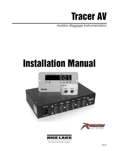
About This <strong>Manual</strong>This manual is intended for use by service techniciansresponsible for installing and servicing <strong>Tracer</strong> <strong>AV</strong>aviation baggage instrumentation. This manualapplies to units using Version 1.14 of the <strong>Tracer</strong> <strong>AV</strong>software.Configuration and calibration of the <strong>Tracer</strong> <strong>AV</strong> can beaccomplished using the 2-button keypad, the EDPcommand set, or the Revolution ® configuration utility.See Section 3.1 on page 10 for information aboutconfiguration methods.1.0 IntroductionThe <strong>Tracer</strong> <strong>AV</strong> is a single-channel digital weightindicator comprised of three components:• The <strong>Tracer</strong> <strong>AV</strong> houses the AC power supplyand CPU board. There are external DB-9connectors for a PC connection, two remotedisplay connections, two remote keypadconnections, and a load cell connection (SeeFigure 2-3 4).• The RD-1 remote display (See Figure 1-1 2)is a large .8 in., six-digit, seven-segment LEDdisplay. There are connectors for two remotedisplays.• The RK-1 keypad (See Figure 1-1 2) has twokeys which are used to zero the scale and totoggle between a primary and secondary unitof measure in the normal mode of operation.These keys have a secondary function for thesetup mode.The <strong>Tracer</strong> <strong>AV</strong> features include:• Four-wire load cell connections; remote senseconnections are not provided.• The electronic data processing (EDP) port isfull duplex; RS-232 communications at up to38400 bps. The EDP port is accessed throughthe COMM connection.• The serial port connects to the RD-1 remotedisplays. The output is RS-232 and will drivetwo RD-1 units.• Print formatting is defaulted for RD-1communications.• Digital inputs are defaulted for RK-1functionality.• Setpoints values will cause the display toflash when a specified weight value isexceeded.• Available for 115 VAC and 230 VAC.Some procedures described in thismanual require work inside the <strong>Tracer</strong><strong>AV</strong> enclosure. These procedures areto be performed by qualified servicepersonnel only.Authorized distributors and their employeescan view or download this manual from the<strong>Rice</strong> <strong>Lake</strong> <strong>Weighing</strong> <strong>Systems</strong> distributorsite at www.ricelake.com.W arning1.1 Operating ModesThe <strong>Tracer</strong> <strong>AV</strong> has three modes of operation:Normal (Primary) modeNormal mode is the default mode of the <strong>Tracer</strong> <strong>AV</strong>.The indicator displays gross or net weights asrequired, using the LED annunciators described inSection 1.3 on page 2 to indicate scale status andthe type of weight value displayed. Onceconfiguration is complete and a legal seal isaffixed, this is the primary mode in which the<strong>Tracer</strong> <strong>AV</strong> can operate.Setup modeMost of the procedures described in this manualrequire the <strong>Tracer</strong> <strong>AV</strong> to be in setup mode,including configuration and calibration.To enter setup mode, remove the setup switchaccess screw on the <strong>Tracer</strong> <strong>AV</strong> (See Figure 2-3 4).Once the screw is removed, use a smallscrewdriver or pen tip to press the setup switch.The display changes to show the word DEFCAL.Test modeTest mode provides a number of diagnosticfunctions for the <strong>Tracer</strong> <strong>AV</strong>. Like setup mode, testmode is entered using the setup switch. SeeSection 6.7 on page 39 for more information.NOTE: Test mode is intended for factory use only.<strong>Tracer</strong> <strong>AV</strong> <strong>Installation</strong> <strong>Manual</strong> - Introduction 1
1.2 Display and KeypadFigure 1-1 shows the <strong>Tracer</strong> <strong>AV</strong> LED display with annunciators and keypad. In setup mode, the keys are used tonavigate through menus, select digits within numeric values, and increment/decrement values. See Section 3.1.3on page 11 for information about using the front panel keys in setup mode..Figure 1-1. RD-1 Front Panel, Showing LED Annunciators (left), and RK-1 2-Button Keypad (right)1.3 LED AnnunciatorsThe <strong>Tracer</strong> <strong>AV</strong> display uses a set of six LED annunciators to provide additional information about the value beingdisplayed:• Gross and Net annunciators are lit to show whether the displayed weight is a gross or net weight.• Center of zero ( ): Gross weight is within 0.25 graduations of zero. This annunciator lights when thescale is zeroed.• Standstill ( ): Scale is at standstill or within the specified motion band. Some operations, includingtare functions and printing, can only be done when the standstill symbol is shown.• lb and kg annunciators indicate the units associated with the displayed value: lb=pounds, kg=kilograms.1.4 <strong>Tracer</strong> <strong>AV</strong> OperationsBasic <strong>Tracer</strong> <strong>AV</strong> operations are summarized below.1.4.1 Toggle UnitsPress the Units key to switch between primary and secondary units. The appropriate units LED under the displayis lit.1.4.2 Zero Scale1. In gross mode, remove all weight from the scale and wait for the standstill annunciator ( ).2. Press the Zero key.The center of zero ( ) annunciator lights to indicate the scale is zeroed.2 <strong>Tracer</strong> <strong>AV</strong> <strong>Installation</strong> <strong>Manual</strong>
2.0 <strong>Installation</strong>This section describes the connections between the DB-9 plugs and the CPU board. This section also includesassembly drawings, connection tables, and parts lists for the service technician.• Use a wrist strap to ground yourself and protect components from electrostatic discharge (ESD) whenworking inside the <strong>Tracer</strong> <strong>AV</strong> enclosure.• This unit uses line fusing which could create an electric shock hazard. Procedures requiring work insidethe <strong>Tracer</strong> <strong>AV</strong> enclosure must be performed by qualified service personnel only.• The supply cord serves as the main power disconnect for the <strong>Tracer</strong> <strong>AV</strong>. The power outlet must beinstalled near the unit and be easily accessible.2.1 Unpacking and AssemblyImmediately after unpacking, visually inspect the <strong>Tracer</strong> <strong>AV</strong> to ensure all components are included andundamaged. The shipping carton should contain the <strong>Tracer</strong> <strong>AV</strong> enclosure, remote display, remote keypad, thismanual, two cables, and a power cord. If any parts were damaged in shipment, notify <strong>Rice</strong> <strong>Lake</strong> <strong>Weighing</strong><strong>Systems</strong> and the shipper immediately.2.2 Enclosure Security/DisassemblyAfter an NTEP inspector has examined the unit, he/she will install security cables pictured in Figure 2-1 andFigure 2-2. These cables prevent the <strong>Tracer</strong> <strong>AV</strong> from being tampered with by an unauthorized individual. If thesecables are removed, NTEP certification will become void.If the <strong>Tracer</strong> <strong>AV</strong> enclosure must be opened by an authorized technician, ensure power is disconnected, then placeit on an anti-static work mat. Cut tamper-proof cables, remove screws, and remove the enclosure’s top cover. AnNTEP inspector will have to examine the unit and attach new security cables.Security cablesFigure 2-1. <strong>Tracer</strong> <strong>AV</strong> (front) security cables installed after NTEP certification.<strong>Tracer</strong> <strong>AV</strong> <strong>Installation</strong> <strong>Manual</strong> - <strong>Installation</strong> 3
Figure 2-2. <strong>Tracer</strong> <strong>AV</strong> (back) security cables installed after NTEP certification.2.3 Cable ConnectionsThe <strong>Tracer</strong> <strong>AV</strong> provides several cable connections: one for the power cord, one to accommodate the load cell,communications, remote displays, and keypads. Figure 2-3 shows the assignments for the <strong>Tracer</strong> <strong>AV</strong> connections.Details on pin assignments are shown in Table 2-1 through Table 2-5.Power CordConnectionDB-9 ConnectionsRemove Screw toAccess Setup SwitchFigure 2-3. <strong>Tracer</strong> <strong>AV</strong> Power Cord Connection, DB-9 Connections, and Setup Switch Access Screw.4 <strong>Tracer</strong> <strong>AV</strong> <strong>Installation</strong> <strong>Manual</strong>
2.3.1 IllustrationsThe following illustrations show the <strong>Tracer</strong> <strong>AV</strong> CPU board, system configuration, remote display cutout, andremote display drawing.DC INPUT1C1C2F1J7R1R2+5V1 J8 9C15C19GD1C3C4ANAME MADHBR15U1R16DISPLA YDRIVERSGNDU2U3U4C5U6C6XT1R9R10C9R11R12C13U9C16C20J101R5U7C7R4R6R7RESETMicr o-pr ocesso rC10U8U10JMP3(Factory Only)ONOF FU118KEYPADCONNECTORVR3C8+3. 3U14A/D CONVERTERC32C33C30G2EC31MECCAR25 +5A VHE_J2U19D1+B112+5VJ6DO2DO1R47DO2LED1DO1GndDIGOUT 1R46LED2Gn d20mA-J420mA+GndSERIALRxDDFB1DFB2TR2TR1OFF TESTTxDGndRxDTxDJ31 EDP/ 1RS-232DI 2DI 1DIGINC65JP2 JP1TVS2 TVS1 TVS3 TVS4 TVS6 TVS5Gn dDI 2DI 1EXC-E XC+SEN-SEN+SIG-SIG+J2J1 1 LOAD CELL 115J12J11KEYPADCONNECTOR1SW1REMOTESETUPSETUPSWITCHFigure 2-4. <strong>Tracer</strong> <strong>AV</strong> CPU BoardRemote Display RD1/#1RevolutionConnectionRemote Display RD1/#2Remote KeypadZEROUNITSRemote KeypadZEROUNITS<strong>Tracer</strong> <strong>AV</strong>85-265 VACCommRemoteDisplay 1RemoteDisplay 2Keypad 1 Keypad 2 Load Cell50-60Hz 2ALoad Cell CableScale BaseFigure 2-5. System Configuration<strong>Tracer</strong> <strong>AV</strong> <strong>Installation</strong> <strong>Manual</strong> - <strong>Installation</strong> 5
Figure 2-6. Remote Display CutoutFigure 2-7. Remote Display Drawing6 <strong>Tracer</strong> <strong>AV</strong> <strong>Installation</strong> <strong>Manual</strong>
Figure 2-8. Switch Panel CutoutFigure 2-9. Switch Panel Drawing2.3.2 Load CellsThe load cell cable is connected to the socketed DB-9 marked load cell. This DB-9 is connected to the CPUboard on J1; see the table below for the pin assignments. The DB-9 is for four-wire installations, so leave sensejumper JP1 and JP2 on.DB-9 J1 Pins Function Pad NumberPin 3 2 -Sig P 13Pin 4 5 +Exc P 12Pin 5ShieldPin 6 6 -Exc P 11Pin 7 1 +Sig P 14Table 2-1. J1 Load CellNOTE: The DB-9 is factory pinned for four-wire connections. Leave sense jumpers JP1 and JP2 on.2.3.3 Serial CommunicationsThe pinned DB-9 connector marked as COMM is connected to EDP port J3. It is bi-directional communicationto be used for a PC connection. Configuration using Revolution® software can be loaded through this connector.<strong>Tracer</strong> <strong>AV</strong> <strong>Installation</strong> <strong>Manual</strong> - <strong>Installation</strong> 7
There are two socketed DB-9 connectors for remote displays which are connected to the serial port J4. Theremote display’s DC power and communications are run in the same three-conductor cable. The serial port datais transmitted on the 20 mA pins to the remote displays.DB-9EDP PortCOMM J3 Function PadPin 2 1 EDP TxD P 1Pin 3 2 EDP RxD P 2Pin 5 3 EDP Gnd P 3Table 2-2. EDP Port/COMDB-9 Serial Port Digital OutputRemote J4 J6 Function Padn/a 4 +5 VDC P 4n/a 4 20 mA+ P 5n/a 5 20 mA- P 6Pin 1 +7.5 VDC n/aPin 2 Gnd n/aPin 9 TxD n/aTable 2-3. Serial Port/Remote Display2.3.4 Digital I/ODigital inputs can be set to provide several indicator functions, including all keypad functions. In the <strong>Tracer</strong> <strong>AV</strong>,these inputs are set to Zero and Units for the remote keypad. The inputs are active (on) with low voltage (0 VDC)and can be driven by TTL or 5V logic without additional hardware. LEDs on the CPU board light when digitalinputs are active.DB-9Digital InputJ2 J12 Function Pad NumberPin 4 1 Setup P 10Pin 5 3 Gnd P 7Pin 8 1 Dig In 1 P 9Pin 9 2 Dig In 2 P 8Table 2-4. Digital Input/Remote KeypadDigital outputs are typically used to control relays that drive other equipment. In the <strong>Tracer</strong> <strong>AV</strong>, the setpoint valuewill cause the display to flash. Outputs are designed to sink not source, switching current. Each output is anormally open connector circuit, capable of sinking 250 mA when active. Digital outputs are wired to switchrelays when the digital output is active (low, 0 VDC) with reference to 5 VDC supply. LEDs on the CPU boardlight when the digital outputs are active.Port Connector Pin FunctionDigitalOutputJ6 1 Gnd2 DO 13 DO 24 +5VTable 2-5. J6 Digital Outputs8 <strong>Tracer</strong> <strong>AV</strong> <strong>Installation</strong> <strong>Manual</strong>
2.4 Board RemovalIf you must remove the <strong>Tracer</strong> <strong>AV</strong> CPU board, use the following procedure:• Use a wrist strap to ground yourself and protect components from electrostatic discharge (ESD) whenworking inside the <strong>Tracer</strong> <strong>AV</strong> enclosure.• This unit uses line fusing which could create an electric shock hazard. Procedures requiring work insidethe <strong>Tracer</strong> <strong>AV</strong> enclosure must be performed by qualified service personnel only.• The supply cord serves as the main power disconnect for the <strong>Tracer</strong> <strong>AV</strong>. The power outlet must beinstalled near the unit and be easily accessible.1. Disconnect power to the <strong>Tracer</strong> <strong>AV</strong>.2. Cut security cable (if installed) and remove screws.3. Remove the top cover.4. Disconnect power supply cable from connector J7 on the <strong>Tracer</strong> <strong>AV</strong> CPU board.5. Unplug connectors J1 (load cell cable), J2 (digital inputs), J3 (EDP), J4 (serial), J6 (digital outputs), andJ2 (display). See Figure 2-4 5 for connector locations.6. Remove the five screws from the CPU board, then lift the board out of the enclosure.To replace the CPU board, reverse the above procedure.2.5 Replacement PartsTable 2-6 lists replacement parts for the <strong>Tracer</strong> <strong>AV</strong>.PN Description (Quantity)97994 <strong>Tracer</strong> <strong>AV</strong> Enclosure Assembly70599 6 Pos Screw Terminal - Pluggable 5mm Center Screws (2)71125 3 Pos Screw Terminal - Pluggable 5mm Center Screws (2)71126 4 Pos Screw Terminal - Pluggable 5mm Center Screws(1)76556 Power Supply (1)87958 CPU Board Assembly (1)97881 Coverplate - 10” x 6 ”x 2” (1)97978 DB-9 PCB Assembly (1)93558 Remote Display93213 Back Cover Enclosure (1)93215 Remote Display Lens (1)93559 Front Panel Assembly (1)93561 PCB Assembly (1)93563 Cable Assembly (1)97995 2-Button Keypad50749 DB-9 FEM to DB-9 Cable (1)71014 Piezo Switch SST SPSI (2)97877 Front Switch Panel (1)97878 Rear Switch Panel Cover (1)97977 PCB Assembly (1)Table 2-6. Replacement Parts<strong>Tracer</strong> <strong>AV</strong> <strong>Installation</strong> <strong>Manual</strong> - <strong>Installation</strong> 9
3.0 ConfigurationTo configure the <strong>Tracer</strong> <strong>AV</strong>, it must be placed in setupmode. Setup mode is initiated by pressing the setupswitch on the <strong>Tracer</strong> <strong>AV</strong> (see Figure 2-3 4).When the <strong>Tracer</strong> <strong>AV</strong> is placed in setup mode, the wordCONFIG is shown on the display. The CONFIG menuis the first of 7 main menus used to configure the<strong>Tracer</strong> <strong>AV</strong>. Detailed descriptions of these menus aregiven in Section 3.2 on page 12. When configurationis complete, continue pressing the (Units) key toexit setup mode.3.1 Configuration MethodsThe <strong>Tracer</strong> <strong>AV</strong> can be configured by using the Zero andUnits keys to navigate through a series ofconfiguration menus or by sending commands orconfiguration data to the EDP port. Configurationusing the menus is described in Section 3.1.3 onpage 11.Configuration using the EDP port can beaccomplished using either the EDP command setdescribed in Section 5.0 or the Revolution® software.3.1.1 Revolution ConfigurationThe Revolution configuration utility provides thepreferred method for configuring the <strong>Tracer</strong> <strong>AV</strong>.Revolution runs on a personal computer to setconfiguration parameters for the <strong>Tracer</strong> <strong>AV</strong>. WhenRevolution configuration is complete, configurationdata is downloaded to the <strong>Tracer</strong> <strong>AV</strong>.To use Revolution, do the following:1. Install the Revolution module on a PCrunning Windows ® 98 or later. Minimumsystem requirements are 4MB of extendedmemory and at least 5MB of available harddisk space.2. With both the <strong>Tracer</strong> <strong>AV</strong> and PC powered off,connect the PC serial port to the <strong>Tracer</strong> <strong>AV</strong>’sEDP port.3. Power up the PC and the <strong>Tracer</strong> <strong>AV</strong>. Use thesetup switch to place the <strong>Tracer</strong> <strong>AV</strong> in setupmode.4. Start the Revolution program.Figure 3-1 shows an example of one of the Revolutionconfiguration displays.Revolution provides online help for each of itsconfiguration displays. Parameter descriptionsprovided in this manual for front panel configurationcan also be used when configuring the <strong>Tracer</strong> <strong>AV</strong> usingRevolution: the interface is different, but theparameters set are the same.3.1.2 EDP Command ConfigurationThe EDP command set can be used to configure the<strong>Tracer</strong> <strong>AV</strong> using a personal computer, terminal, orremote keyboard. Like Revolution, EDP commandconfiguration sends commands to the <strong>Tracer</strong> <strong>AV</strong> EDPport; unlike Revolution, EDP commands can be sentusing any external device capable of sending ASCIIcharacters over a serial connection.EDP commands duplicate the functions availableusing the <strong>Tracer</strong> <strong>AV</strong> front panel and provide somefunctions not otherwise available. EDP commands canbe used to simulate pressing front panel keys, toconfigure the <strong>Tracer</strong> <strong>AV</strong>, or to dump lists of parametersettings. See Section 5.0 on page 26 for moreinformation about using the EDP command set.Figure 3-1. Sample Revolution Configuration DisplayRevolution supports both uploading and downloadingof configuration data. This capability allowsconfiguration data to be retrieved from one <strong>Tracer</strong> <strong>AV</strong>,edited, then downloaded to another.10 <strong>Tracer</strong> <strong>AV</strong> <strong>Installation</strong> <strong>Manual</strong>
3.1.3 Front Panel ConfigurationThe <strong>Tracer</strong> <strong>AV</strong> can be configured using a series of menus viewed on the RD-1 display when the <strong>Tracer</strong> <strong>AV</strong> is insetup mode. Table 3-1 summarizes the functions of each of the main menus.DEFCALMenuDefaultConfigurationMenu FunctionSelect a 500lb or 300lb default configuration. You can also display and edit zero calibration a/dcount value, test weight value, and span calibration a/d count value.CONFIG Configuration Configure grads, zero tracking, zero range, motion band, overload, tare function, sample rate,and digital filtering parameters.FORMAT Format Set format of primary and secondary units, display rate.CALIBR Calibration Calibrate <strong>Tracer</strong> <strong>AV</strong>. See Section 4.0 on page 23 for calibration procedures.SERIAL Serial Configure EDP and printer serial ports.PROGRM Program Set power-up mode, regulatory mode, and consecutive number values.SETPNT Setpoint Configure Setpoints and digital outputs.VERS Version Display installed software version number.Table 3-1. <strong>Tracer</strong> <strong>AV</strong> Menu SummaryButtonFunctionZeroMove DOWN/ Increment ValueUnitsMove RIGHT/NextTable 3-2. Button Functions in Setup ModeThe two-button numeric editor works as follows:Press Units to navigate RIGHT. Press Zero to drop DOWN or select from a list of values.1 st LevelParameter1 st LevelParameter2 nd LevelParameter2 nd LevelParameterDefault valueValueValueValueWhen moving through values below the first menu, press UNITS to view theselections. Press ZERO to set the parameter and move to the next parameter on theleval above.Figure 3-2. Setup Mode Menu Navigation3.1.4 Setting Numeric Values For Parameters1. Press Zero to immediately accept the current value and navigate to the next menu item.2. Press Units to enter edit mode.The leftmost digit will flash to indicate it can be altered.3. Press Zero to increment to the desired value.4. When the value is correct, press Units to move to the next digit.<strong>Tracer</strong> <strong>AV</strong> <strong>Installation</strong> <strong>Manual</strong> - Configuration 11
3.1.5 Editing Integers1. By pressing Units , navigate all the way to theright (beyond all ‘-’ characters until there are nosegments flashing).NOTE: The ‘-’ characters are placeholders for appending orremoving digits at the end of numbers that exceed thesix-digit display.2. Press Zero to accept the modified value.3.1.6 Editing Floating Point (Decimal Point Position)1. By pressing Units , navigate all the way to theright (beyond all ‘-’ characters until there are nosegments flashing).2. Press Zero to initialize editing of decimal pointposition.3. Press Units to move the decimal point to the desired position.The decimal point will move forward one position with the UnitsIncrement Value/Save Value EnteredAnd Return to LevelAbovebutton is pressed to select the position.4. When the decimal point is in the desired position, press Zero .Change Digit SelectionFigure 3-3. Editing Procedure for Numeric Valuesbutton and wrap around until the Zero3.2 Menu Structures and Parameter DescriptionsThe following sections provide graphic representations of the <strong>Tracer</strong> <strong>AV</strong> menu structures. In the actual menustructure, the settings you choose under each parameter are arranged horizontally. To save page space, menuchoices are shown in vertical columns. The factory default setting appears at the top of each column in bold type.Most menu diagrams are accompanied by a table that describes all parameters and parameter values associatedwith that menu. Default parameter values are shown in bold type.3.2.1 Default Calibration MenuXXXXXXX DEFCALCONFIG XXXXXXX FORMAT CALIBR SERIAL PROGRM XXXXXXX SETPNT VERSSELECT WZEROWV AL WSPAN500lb300lbFigure 3-4. Default Calibration MenuDEFCAL MenuParameter Choices DescriptionSELECT500lb300lb500lb sets the scale to a primary of 500lb x 1 lb and a secondary of 250kg x .5 kg ;SP1 trip=50lb; SP2=off; Dig Filter 1=8; Dig Filter 2=8; Dig Filter 3=8; Zero Tracking=3D300lb sets the scale to a primary of 300lb x 1 lb and a secondary of 150kg x .5kgSP1 trip=50lb; SP2=off; Dig Filter 1=8; Dig Filter 2=8; Dig Filter 3=8; Zero Tracking = 3DWZERO — Display and edit the zero calibration A/D count value.DO NOT adjust this value after WSPAN has been set!WVAL — Display and edit the test weight value.WSPAN — Display and edit the span calibration A/D count value.Table 3-3. Default Calibration Parameters12 <strong>Tracer</strong> <strong>AV</strong> <strong>Installation</strong> <strong>Manual</strong>
3.2.2 Configuration MenuDEFCALCONFIGXXXXXXX FORMATCALIBRSERIALPROGRMXXXXXXX SETPNTVERSGRADSZTRKBNZRANGEMOTBANOVRLOASMPRAT10000 1.9000001FS+2%15HZnumbernumber number numberFS+1D30HZFS+9D60HZFS7.5HZDIGFL1DIGFL2DIGFL3DFSENSDFTHRHT AREFN8888OUTNONEBOTH16161616OUT2DDNOT ARE32323232OUT5DDPBTARE64646464OUT10DDKEYED111128OUT20DD2222OUT50DD4444OUT100DD200DD250DDFigure 3-5. Configuration MenuCONFIG MenuParameter Choices DescriptionLevel 2 submenusGRADS 1000numberZTRKBN 0numberZRANGE 1.900000numberGraduations. Specifies the number of full scale graduations. The value entered must be inthe range 1–100 000 and should be consistent with legal requirements and environmentallimits on system resolution.To calculate GRADS, use the formula, GRADS = Capacity / Display Divisions.Display divisions for primary and secondary units are specified on the FORMAT menu.Automatically zeroes the scale when within the range specified, as long as the input iswithin the ZRANGE and scale is at standstill. Specify the zero tracking band in ± displaydivisions. Maximum legal value varies depending on local regulations.NOTE: For scales using linear calibration, do not set the zero tracking band to a valuegreater than that specified for the first linearization point.Selects the range within which the scale can be zeroed. The 1.900000 default value is ±1.9% around the calibrated zero point, for a total range of 3.8%. Indicator must be atstandstill to zero the scale. Use the default value for legal-for-trade applications.Table 3-4. Configuration Menu Parameters<strong>Tracer</strong> <strong>AV</strong> <strong>Installation</strong> <strong>Manual</strong> - Configuration 13
CONFIG MenuMOTBAN 1numberOVRLOASMPRATDIGFL1DIGFL2DIGFL3Parameter Choices DescriptionDFSENSDFTHRHTAREFNFS+2%FS+1DFS+9DFS15HZ30HZ60HZ7.5HZ81632641248OUT16OUT32OUT64OUT128OUT2OUT4OUTNONE2DD5DD10DD20DD50DD100DD200DD250DDBOTHNOTAREPBTAREKEYEDSets the level, in display divisions, at which scale motion is detected. If motion is notdetected for 1 second or more, the standstill symbol lights. Some operations, includingprint, tare, and zero, require the scale to be at standstill. Maximum legal value variesdepending on local regulations.If this parameter is set to 0, the standstill annunciator will be set continuously on, andoperations including zero, print, and tare will be performed regardless of scale motion. If 0is selected, ZTRKBND must also be set to 0.Overload. Determines the point at which the display blanks and an out-of-range errormessage is displayed. Maximum legal value varies depending on local regulations.Sample rate. Selects measurement rate, in samples per second, of the analog-to-digitalconverter. Lower sample rate values provide greater signal noise immunity.Digital filtering. Selects the digital filtering rate used to reduce the effects of mechanicalvibration from the immediate area of the scale.Choices indicate the number of A/D conversions that are averaged to obtain thedisplayed reading. A higher number gives a more accurate display by minimizing theeffect of a few noisy readings, but slows down the settling rate of the indicator. SeeSection 6.6 on page 37 for more information on digital filtering.Digital filter cutout sensitivity. Specifies the number of consecutive readings that must falloutside the filter threshold (DFTHRH parameter) before digital filtering is suspended. IfNONE is selected, the filter is always enabled.Digital filter cutout threshold. Specifies the filter threshold, in display divisions. When aspecified number of consecutive scale readings (DFSENS parameter) fall outside of thisthreshold, digital filtering is suspended. If NONE is selected, the filter is always enabled.Tare function. Enables or disables push-button and keyed tares. Possible values are:BOTH:Both push-button and keyed tares are enabledNOTARE:No tare allowed (gross mode only)PBTARE:Push-button tares enabledKEYED:Keyed tare enabledTable 3-4. Configuration Menu Parameters (Continued)14 <strong>Tracer</strong> <strong>AV</strong> <strong>Installation</strong> <strong>Manual</strong>
3.2.3 Format MenuDEFCALCONFIGXXXXXXX FORMATCALIBRSERIALPROGRMXXXXXXX SETPNTVERSPRIMARSECNDRDSPRATDECPNTDSPDIVUNITSDECPNTDSPDIVUNITSMULT250MS500MS88888.888888. 85D1DLBKG88888.88888885D1DKGOZ0.453592number750MS1SEC8888808.888882DOZTN8888808.888882DTNTOnly used ifUNITS =NONE1.5SEC2SEC88.8888T88.8888G2.5SEC888.888G888.888NONE3SEC8888.88NONE8888.88LB4SEC6SEC8SECFigure 3-6. Format MenuFORMAT MenuParameter Choices DescriptionLevel 2 submenusPRIMARDECPNTDSPDIVUNITSSpecifies the decimal position, display divisions, and units used for the primary units. SeeLevel 3 submenu parameter descriptions.SECNDRDSPRATDECPNTDSPDIVUNITSMULT250MS500MS750MS1SEC1.5SEC2SEC2.5SEC3SEC4SEC6SEC8SECSpecifies the decimal position, display divisions, units, and conversion multiplier used forthe secondary units. See Level 3 submenu parameter descriptions.Display rate. Sets the update rate for displayed values. Values are in milliseconds (MS) orseconds (SEC).Table 3-5. Format Menu Parameters<strong>Tracer</strong> <strong>AV</strong> <strong>Installation</strong> <strong>Manual</strong> - Configuration 15
FORMAT MenuLevel 3 submenusPrimary Units (PRIMAR Parameter)DECPNT 88888.88888888888808.8888888.8888888.8888888.88DSPDIVUNITS5D1D2DLBKGOZTNTGNONESecondary Units (SECNDR Parameter)DECPNT 88888.88888888888808.8888888.8888888.8888888.88DSPDIVUNITSParameter Choices Description5D1D2DKGOZTNTGNONELBMULT 0.453592Enter otherchoices viakeyboardDecimal point location. Specifies the location of the decimal point or dummy zeroes in theprimary unit display. Value should be consistent with local legal requirements.Display divisions. Selects the minimum division size for the primary units displayed weight.Specifies primary units for displayed and printed weight. Values are: LB=pound;KG=kilogram; OZ=ounce; TN=short ton; T=metric ton; G=gramNOTE: Indicators sold outside North America are configured with KG for bothprimary and secondary units.Decimal point location. Determines the location of the decimal point or dummy zeros inthe secondary unit display.Display divisions. Selects the value of minimum division size of the displayed weight.Specifies secondary units for displayed and printed weight. Values are: KG=kilogram;OZ=ounce; TN=short ton; T=metric ton; G=gram; LB=pound.Multiplier. Specifies the conversion factor by which the primary units are multiplied toobtain the secondary units. The default is 0.453592, which is the conversion factor forchanging pounds to kilograms. See Section 6.5 on page 36 for a list of multipliers.NOTE: Multipliers are pre-configured within the indicator. <strong>Manual</strong> entry is onlynecessary when NONE is selected under UNITS.To toggle between primary and secondary units, press the Units key.Table 3-5. Format Menu Parameters (Continued)16 <strong>Tracer</strong> <strong>AV</strong> <strong>Installation</strong> <strong>Manual</strong>
3.2.4 Calibration MenuSee Section 4.0 on page 23 for calibration procedures.DEFCALCONFIGXXXXXXX FORMATCALIBRSERIALPROGRMXXXXXXX SETPNTVERSWZERO WV AL WSPANREZEROPress Zero key toremove offset fromzero and spancalibrationsFigure 3-7. Calibration MenuCALIBR MenuParameter Choices DescriptionLevel 2 submenusWZERO — Display and edit the zero calibration A/D count value.DO NOT adjust this value after WSPAN has been set!WVAL — Display and edit the test weight value.WSPAN — Display and edit the span calibration A/D count value.REZERO — Press Zero to remove an offset value from the zero and span calibrations.Use this parameter only after WZERO and WSPAN have been set. See Section 4.2 onpage 24 for more information about using this parameter.Table 3-6. Calibration Menu Parameters3.2.5 Serial MenuSee Section 6.3 on page 34 for information about the <strong>Tracer</strong> <strong>AV</strong> serial data format.DEFCALCONFIGFORMAT XXXXXXXCALIBRSERIALPROGRMXXXXXXX SETPNTVERSEDPBAUDBITSTERMINEOLDLYECHO96008NONECR/LF000ON192007EVENCRnumberOFF384007ODD300600120024004800Figure 3-8. Serial Menu<strong>Tracer</strong> <strong>AV</strong> <strong>Installation</strong> <strong>Manual</strong> - Configuration 17
3.2.6 Program MenuDEFCALCONFIGXXXXXXX FORMATCALIBRSERIALPROGRMXXXXXXX SETPNTVERSPWRUPMREGULACONSNUCONSTUUIDDA TETIMEGONTEP0000000000001DA TFMTDA TSEPTIMFMTTIMSEPDELAYOIMLnumbernumberMMDDYYSLASH24HOURCOLONCANADADDMMYYDASH12HOURCOMANONEYYMMDDSEMIYYDDMMFigure 3-9. Program MenuPROGRM MenuParameter Choices DescriptionLevel 2 submenusPWRUPM GODELAYPower up mode. In GO mode, the indicator goes into operation immediately after a brief powerup display test.REGULANTEPOIMLCANADANONEIn DELAY mode, the indicator performs a power up display test, then enters a 30-secondwarm up period. If no motion is detected during the warm up period, the indicator becomesoperational when the warm up period ends; if motion is detected, the delay timer is reset andthe warm up period repeated.Regulatory mode. Specifies the regulatory agency having jurisdiction over the scale site.OIML, NTEP, and CANADA modes allow a tare to be acquired at any weight greater than zero.NONE allows tares to be acquired at any weight value.OIML, NTEP, and CANADA modes allow a tare to be cleared only if the gross weight is at noload. NONE allows tares to be cleared at any weight value.NTEP and OIML modes allow a new tare to be acquired even if a tare is already present. InCANADA mode, the previous tare must be cleared before a new tare can be acquired.NONE, NTEP and CANADA modes allow the scale to be zeroed in either gross or net mode aslong as the current weight is within the specified ZRANGE. In OIML mode, the scale must be ingross mode before it can be zeroed; pressing the ZERO key in net mode clears the tare.UID 1 Specifies the unit identification number. Value specified can be any numeric value, up to sixdigits.DATE DATFMT Allows selection of date format and date separator. See Level three parameter for descriptions.DATSEPTIME TIMFMTTIMSEPAllows selection of time format and separator. See level three parameter for descriptions.CONSNU 000000numberCONSTU 000000numberConsecutive numbering. Allows sequential numbering for print operations. The consecutivenumber value is incremented following each print operation.The initial value of this parameter is set to the start up value specified on the CONSTUparameter. Changing either CONSTU or CONSNU immediately resets the consecutive numberused for printing.Consecutive number start up value. Specifies the initial consecutive number (CONSNU) valueused when the indicator is powered on.Table 3-8. Program Menu Parameters<strong>Tracer</strong> <strong>AV</strong> <strong>Installation</strong> <strong>Manual</strong> - Configuration 19
PROGRM MenuParameter Choices DescriptionLevel 3 submenusDATFMT MMDDYYDDMMYYYYMMDDDATSEPTIMFMTTIMSEPSLASHDASHSEMI24HOUR12HOURCOLANCOMMASpecifies the format used to display or print the date.Specifies the date separator character.Specifies the format used to display or print the time.Specifies the time separator character.Table 3-8. Program Menu Parameters (Continued)20 <strong>Tracer</strong> <strong>AV</strong> <strong>Installation</strong> <strong>Manual</strong>
4.0 CalibrationThe <strong>Tracer</strong> <strong>AV</strong> can be calibrated using the Zero and Units keys, EDP commands, or the Revolution ® configurationutility. Each method consists of the following steps:• Zero calibration• Entering the test weight value• Span calibration• Optional rezero calibration for test weightsusing hooks or other additional items.DEFCALCONFIGXXXXXXX FORMATCALIBRSERIALPROGRMXXXXXXX SETPNTVERSWZERO WV AL WSPANREZEROZeroFigure 4-1. Calibration (CALIBR) MenuYou can also use the default calibration feature, which utilizes a more user-friendly procedure; however, not alloptions are available in default calibration.XXXXXXX DEFCALCONFIG XXXXXXX FORMAT CALIBR SERIAL PROGRM XXXXXXX SETPNT VERSSELECT WZEROWV AL WSPAN500lb300lbFigure 4-2. Default Calibration (DEFCAL) Menu4.1 Default CalibrationIf you use a 500lb or 300lb scale, you can select itfrom the DEFCAL menu. This automatically uses thesettings shown in Table 4-1. for 500lbs or Table 4-2.for 300lbs.Primary500lb x 1lbSecondary 250kg x .5kgSP1 Trip50lbSP2OffDigital Filter 8,8,8Zero Tracking3DTable 4-1. 500lb scale settingsPrimary300lb x 1lbSecondary 150kg x .5kgSP1 Trip50lbSP2OffDigital Filter 8,8,8Zero Tracking3DTable 4-2. 300lb scale settingsTo calibrate the <strong>Tracer</strong> <strong>AV</strong> using the Zero and Unitskeys, do the following:1. Place the <strong>Tracer</strong> <strong>AV</strong> in setup modeTo enter setup mode, remove the setup switchaccess screw on the <strong>Tracer</strong> <strong>AV</strong> (See Figure 2-34). Once the screw is removed, use a smallscrewdriver to press the setup switch. Thedisplay changes to show the word DEFCAL.2. Remove all weight from the scale platform. Ifyour test weights require hooks or otheritems, place them on the scale.3. Press the Zero key to go to SELECT.4. Press the Units key to go to zero calibration(WZERO).5. Press the Zero key to calibrate zero. Theindicator displays *CAL* while calibration is inprogress. When complete, the A/D count forthe zero calibration is displayed. DO NOTadjust this value after WSPAN has been set!Press Zero again to save the zero calibrationvalue and go to the next prompt (WVAL).<strong>Tracer</strong> <strong>AV</strong> <strong>Installation</strong> <strong>Manual</strong> - Calibration 23
4.4 Revolution ® CalibrationTo calibrate the <strong>Tracer</strong> <strong>AV</strong> using Revolution, the EDPport must be connected to a PC running theRevolution configuration utility.Use the following procedure to calibrate the <strong>Tracer</strong><strong>AV</strong>:1. Select Calibration Wizard from the Revolutiontools menu.2. Revolution uploads calibration data from the<strong>Tracer</strong> <strong>AV</strong> then presents the information in adisplay like that shown in Figure 4-3.Figure 4-3. Revolution Calibration Display3. Enter the Value of Test Weight to be used forspan calibration then click OK.4. The Zero Calibration dialog box prompts youto remove all weight from the scale. Clear thescale and click OK to begin zero calibration.NOTE: If your test weights require hooks or other items,place them on the scale for zero calibration.5. When zero calibration is complete, the SpanCalibration dialog box prompts you to placetest weights on the scale for span calibration.Place tests weights on the scale then click OK.6. When calibration is complete, the New Settingsfields of the Indicator Calibration display arefilled in. Click Exit to save the new values andreturn to the Revolution main menu; to restorethe previous calibration values, click RestoreSettings.4.5 More About CalibrationThe following topics provide additional informationabout compensating for environmental factors(Section 4.5.1) and diagnostic information fordetermining expected zero and span coefficients.4.5.1 Adjusting Final CalibrationCalibration may be affected by environmental factorsincluding wind, vibration, and angular loading. Forexample, if the scale is calibrated with 1000 lb, astrain test may determine that at 2000 lb thecalibration is 3 lb high. In this case, final calibrationcan be adjusted by tweaking WVAL to 998.5 lb. Thisadjustment provides a linear correction of 1.5 lb per1000 lb.To adjust the final calibration, return to the WVALprompt and press Zero to show the test weightvalue. Press Units to adjust calibration up or down.Press Zero to save the value, then press Units toreturn to the CALIBR menu.4.5.2 A/D CountsTable 4-3 lists the ideal A/D counts that result frominput signals of 0–3.0 mV with zero deadload. Actualvalues will typically be higher than the values shownin Table 4-3, but the ideal values can be used whencalibrating the <strong>Tracer</strong> <strong>AV</strong> with no attached scale.Input Signal (mV)Raw A/D Counts0.0 mV/V 167,8400.5 mV/V 335,6131.0 mV/V 503,3771.5 mV/V 671,1432.0 mV/V 838,9082.5 mV/V 1,100,6683.0 mV/V 1,174,446Table 4-3. Ideal A/D Raw CountsNOTE: When Raw A/D Count is displayed, the six mostsignificant digits appear. Scroll left or right to see the fullvalue.<strong>Tracer</strong> <strong>AV</strong> <strong>Installation</strong> <strong>Manual</strong> - Calibration 25
5.0 EDP CommandsThe <strong>Tracer</strong> <strong>AV</strong> can be controlled by a personalcomputer or remote keyboard connected to the EDPport. Control is provided by a set of EDP commandsthat can simulate front panel key press functions,display and change setup parameters, and performreporting functions. The EDP port provides thecapability to print configuration data or to save thatdata to an attached personal computer. This sectiondescribes the EDP command set and procedures forsaving and transferring data using the EDP port.5.1 The EDP Command SetThe EDP command set can be divided into fivegroups: key press commands, reporting commands,the RESETCONFIGURATION special functioncommand, parameter setting commands, and transmitweight data commands.When the <strong>Tracer</strong> <strong>AV</strong> processes an EDP command, itresponds with the message OK. The OK responseverifies that the command was received and has beenexecuted. If the command is unrecognized or cannotbe executed, the indicator responds with ??.The following sections list the commands andcommand syntax used for each of these groups.5.1.1 Key Press CommandsKey press EDP commands (see Table 5-1) simulatepressing the keys on the 2-button keypad. Mostcommands can be used in both setup and weighingmode. Several of the commands serve as “pseudo”keys, providing functions that are not represented by akey on the front panel.For example, to enter a 15-pound tare weight usingEDP commands:1. Type K1 and press ENTER2. Type K5 and press ENTER3. Type KTARE and press ENTERThe display shifts to net mode when the tare isentered.CommandFunctionKZEROIn weighing mode, press the Zero keyKGROSSNET In weighing mode, press the GROSS/NET keyKGROSS Go to gross mode*KNETGo to net mode*KTAREPress the TARE keyKUNITSIn weighing mode, press the Units keyKPRIMGo to primary units*KSECGo to secondary units*KPRINTIn weighing mode, press the PRINT keyKLEFTARROW In setup mode, move left in the menuKRIGHTARROW In setup mode, move right in the menuKUPARROW In setup mode, move up in the menuKDOWNARROW In setup mode, move down in the menuKTIMEPress the TIME/DATE key once*KDATEPress the TIME/DATE key twice*KDISPTARE Press the DISPLAY TARE key*KCLRPress the CLEAR key*K0Press number 0 (zero)*K1 Press number 1*K2 Press number 2*K3 Press number 3*K4 Press number 4*K5 Press number 5*K6 Press number 6*K7 Press number 7*K8 Press number 8*K9 Press number 9*KDOT Press the decimal point (.)*KENTER Press the ENTER key* Pseudo keysTable 5-1. EDP Key Press Commands26 <strong>Tracer</strong> <strong>AV</strong> <strong>Installation</strong> <strong>Manual</strong>
5.1.2 Reporting CommandsReporting commands (see Table 5-2) send specificinformation to the EDP port. These commands can beused in both setup mode and normal mode.CommandDUMPALLVERSIONPZZSFunctionList all parameter values<strong>Tracer</strong> <strong>AV</strong> software versionWrite current displayed weight with unitsidentifier. See Section 6.2 on page 33 formore information.Write current weight and annunciatorstatus. See Section 6.2 on page 33 formore information.Write one frame of stream format. SeeTable 5-12 on page 30 for informationabout the SX and EX commands.Table 5-2. EDP Reporting Commands5.1.3 The RESETCONFIGURATION CommandThe RESETCONFIGURATION command can be used torestore all configuration parameters to their defaultvalues. Before issuing this command, the <strong>Tracer</strong> <strong>AV</strong>must be placed in test mode (press and hold setupswitch for approximately three seconds to show TESTmenu).This command is equivalent to using the DEFLTfunction on the TEST menu. See Section 6.7 onpage 39 for more information about test mode andusing the TEST menu.NOTE: All load cell calibration settings are lost when theRESETCONFIGURATION command is run.5.1.4 Parameter Setting CommandsParameter setting commands allow you to display orchange the current value for a particular configurationparameter (Tables 5-3 through 5-11).Current configuration parameter settings can bedisplayed in either setup mode or normal mode usingthe following syntax:commandMost parameter values can be changed in setup modeonly. Use the following command syntax whenchanging parameter values:command=valuewhere value is a number or a parameter value. Use nospaces before or after the equal (=) sign. If you type anincorrect command or value, the display reads??.Changes to the parameters are saved as they areentered but typically do not take effect until you exitsetup mode.For example, to set the motion band parameter to 5,type the following:MOTBAND=5D5.1.5 Soft ResetThe RS command will reset the <strong>Tracer</strong> <strong>AV</strong> withoutlosing configuration and calibration. It does resetconsecutive number.Command Description ValuesDEFCAL Default Calibration 300lb, 500lbGRADS Graduations 1–100 000ZTRKBND Zero track band OFF, 0.5D, 1D, 3DZRANGE Zero range 1.9%, 100%MOTBAND Motion band 1D, 2D, 3D, 5D, 10D, 20D, OFFOVRLOAD Overload FS+2%, FS+1D, FS+9D, FSSMPRAT Sample rate 15HZ, 30HZ, 60HZ, 7.5HZDIGFLTR1DIGFLTR2DIGFLTR3Digital filtering 1, 2, 4, 8, 16, 32, 64DFSENS Digital filter cutout sensitivity 2OUT, 4OUT, 8OUT, 16OUT, 32OUT, 64OUT, 128OUTDFTHRH Digital filter cutout threshold NONE, 2DD, 5DD, 10DD, 20DD, 50DD, 100DD, 200DD, 250DDTAREFN Tare function BOTH, NOTARE, PBTARE, KEYEDTable 5-3. CONFIG EDP Commands<strong>Tracer</strong> <strong>AV</strong> <strong>Installation</strong> <strong>Manual</strong> - EDP Commands 27
Command Description ValuesPRI.DECPNT Primary units decimal position 8.88888, 88.8888, 888.888, 8888.88, 88888.8, 888888, 888880PRI.DSPDIV Primary units display divisions 1D, 2D, 5DPRI.UNITS Primary units LB, KG, OZ, TN, T, G, NONESEC.DECPNT Secondary units decimal position 8.88888, 88.8888, 888.888, 8888.88, 88888.8, 888888, 888880SEC.DSPDIV Secondary units display divisions 1D, 2D, 5DSEC.UNITS Secondary units LB, KG, OZ, TN, T, G, NONESEC.MULT Secondary units multiplier 0.00000–9999.99DSPRATE Display rate 250MS, 500MS, 750MS, 1SEC, 1.5SEC, 2SEC, 2.5SEC, 3SEC,4SEC, 6SEC, 8SECTable 5-4. FORMAT EDP CommandsCommand Description ValuesWZERO Zero calibration —WVAL Test weight value test_weight_valueWSPAN Span calibration —REZERO Rezero —LC.CD Set deadload coefficient valueLC.CW Set span coefficient valueTable 5-5. CALIBR EDP CommandsCommand Description ValuesEDP.BAUD EDP port baud rate 300, 600, 1200, 2400, 4800, 9600, 19200, 38400EDP.BITS EDP port data bits/parity 8NONE, 7EVEN, 7ODDEDP.TERMIN EDP port termination character CR/LF, CREDP.EOLDLY EDP port end-of-line delay 0–255 (0.1-second intervals)EDP.ECHO EDP port echo ON, OFFPRN.BAUD Printer port baud rate 19200PRN.BITS Printer port data bits/parity 8NONE, 7EVEN, 7ODDPRN.TERMIN Printer port termination character CR/LF, CRPRN.EOLDLY Printer port end-of-line delay 0–255 (0.1-second intervals)PRN.ECHO Printer port echo ON, OFFSTREAM Streaming port OFF, EDP, PRNSTRRTE Stream rate INDUST, LFTPRNDEST Print destination EDP, PRNTable 5-6. SERIAL EDP CommandsCommand Description ValuesPWRUPMD Power up mode GO, DELAYREGULAT Regulatory compliance NTEP, OIML, CANADA, NONETable 5-7. PROGRM EDP Commands28 <strong>Tracer</strong> <strong>AV</strong> <strong>Installation</strong> <strong>Manual</strong>
Command Description ValuesCONSNUM Consecutive number 0–999 999CONSTUP Consecutive number start-up value 0–999 999DATEFMT Date format MMDDYY, DDMMYY, YYMMDD, YYDDMMDATESEP Date separator SLASH, DASH, SEMITIMEFMT Time format 12HOUR, 24HOURTIMESEP Time separator COLON, COMMATable 5-7. PROGRM EDP CommandsCommand Description ValuesGFMTNFMTGross demand print format stringNet demand print format stringTable 5-8. PFORMT EDP CommandsCommand Description ValuesSP1SP2SP1.ENABLE SP2.ENABLE Setpoint enable OFF, ONSP1.KIND SP2.KIND Setpoint kind GROSS, NETSP1.VALUE SP2.VALUE Setpoint value numberSP1.TRIP SP2.TRIP Trip Higher, Lower, Inband, OutbndSP1.BNDVAL SP2.BNDVAL Band value numberSP1.HYSTER SP2.HYSTER Hysteresis numberSP1.ACCESS SP2.ACCESS Setpoint access OFF, ONTable 5-9. SETPNTS EDP CommandsCommand Description ValuesDIGIN1DIGIN2Digital input functionOFF, ZERO, TARE, NT/GRS, UNITS, DSPTAR, PRINT, CLRCN,KBDLOC, HOLD, NEWIDTable 5-10. DIG IN EDP CommandsCommand Description ValuesSOURCE Analog output source GROSS, NETOFFSET Zero offset 0%, 20%ERRACT Error action FULLSC, HOLD, ZEROSCMIN Minimum value tracked 0–999 999MINNEG Minimum negative OFF, ONMAX Maximum value tracked 0–999 999MAXNEG Maximum negative OFF, ONTWZERO Zero calibration 0–16 383TWSPAN Span calibration 0–16 383Table 5-11. ALGOUT EDP Commands<strong>Tracer</strong> <strong>AV</strong> <strong>Installation</strong> <strong>Manual</strong> - EDP Commands 29
5.1.6 Normal Mode CommandsThe serial transmit weight data commands (see Table 5-12) transmit data to the EDP port on demand. The SXand EX commands are valid only in normal operating mode; all other commands are valid in either setup ornormal mode.Command Description Response FormatUID Set unit ID nnnnnnnSD Set date MMDDYY, DDMMYY, YYMMDD (enter using DATEFMTspecified)ST Set time hhmm (enter using 24-hour format)SX Start EDP streaming OK or ??EX Stop EDP streaming OK or ??RS Reset system —XG Transmit gross weight in displayed units nnnnnn UUXN Transmit net weight in displayed unitswhere nnnnnn is the weight value, UU is the units.XT Transmit tare weight in displayed unitsXG2 Transmit gross weight in non-displayed unitsXN2 Transmit net weight in non-displayed unitsXT2 Transmit tare weight in non-displayed unitsXE Query system error conditions nnnnn nnnnnSee Section 6.1.2 on page 33 for detailed information aboutthe XE command response format.Table 5-12. Normal Mode Commands30 <strong>Tracer</strong> <strong>AV</strong> <strong>Installation</strong> <strong>Manual</strong>
5.2 Saving and Transferring DataConnecting a personal computer to the <strong>Tracer</strong> <strong>AV</strong> EDPport allows you to save configuration data to the PC orto download configuration data from the PC to a<strong>Tracer</strong> <strong>AV</strong>. The following sections describe theprocedures for these save and transfer operations.5.2.1 Saving <strong>Tracer</strong> <strong>AV</strong> Data to a Personal ComputerConfiguration data can be saved to a personalcomputer connected to the EDP port. The PC must berunning a communications program such asPROCOMMPLUS ® . See Section 2.3.3 on page 7 forinformation about serial communications wiring andEDP port pin assignments.When configuring the <strong>Tracer</strong> <strong>AV</strong>, ensure that thevalues set for the BAUD and BITS parameters on theSERIAL menu match the baud rate, bits, and paritysettings configured for the serial port on the PC. Setthe PRNDEST parameter to EDP.To save all configuration data, place the <strong>Tracer</strong> <strong>AV</strong> insetup mode and send the DUMPALL EDP command.The <strong>Tracer</strong> <strong>AV</strong> responds by sending all configurationparameters to the PC as ASCII-formatted text.5.2.2 Downloading Configuration Data from PC to<strong>Tracer</strong> <strong>AV</strong>Configuration data saved on a PC or floppy disk canbe downloaded from the PC to a <strong>Tracer</strong> <strong>AV</strong>. Thisprocedure is useful when a number of <strong>Tracer</strong> <strong>AV</strong>s withsimilar configurations are set up or when a <strong>Tracer</strong> <strong>AV</strong>is replaced.To download configuration data, connect the PC to theEDP port as described in Section 5.2.1. Place the<strong>Tracer</strong> <strong>AV</strong> in setup mode and use the PCcommunications software to send the savedconfiguration data to the <strong>Tracer</strong> <strong>AV</strong>. When transfer iscomplete, calibrate the <strong>Tracer</strong> <strong>AV</strong> as described inSection 4.0.NOTES:• Calibration settings are included in theconfiguration data downloaded to the <strong>Tracer</strong><strong>AV</strong>. If the receiving <strong>Tracer</strong> <strong>AV</strong> is a directreplacement for another <strong>Tracer</strong> <strong>AV</strong> and theattached scale is not changed, recalibration isnot required.• When downloading configurations thatinclude changed serial communicationssettings, edit the data file to place the serialcommunications changes at the end of thefile. Communication between the PC and<strong>Tracer</strong> <strong>AV</strong> will be lost once the <strong>Tracer</strong> <strong>AV</strong>receives settings for baud rate (BAUDparameter) or data bits and parity (BITSparameter) that do not match those configuredfor the PC.<strong>Tracer</strong> <strong>AV</strong> <strong>Installation</strong> <strong>Manual</strong> - EDP Commands 31
6.0 Appendix6.1 Error MessagesThe <strong>Tracer</strong> <strong>AV</strong> provides a number of error messages. When an error occurs, the message is shown on the remotedisplay. Error conditions can also be checked remotely by using the XE EDP command as described inSection 6.1.2 on page 33.6.1.1 Displayed Error MessagesThe <strong>Tracer</strong> <strong>AV</strong> provides a number of front panel error messages to assist in problem diagnosis. Table 6-1 liststhese messages and their meanings.Error Message Description SolutionE A/D A/D physical error Call <strong>Rice</strong> <strong>Lake</strong> <strong>Weighing</strong> <strong>Systems</strong> (RLWS) Service.EEEROM EEPROM physical errorEVIREE Virgin EEPROM Use TEST menu to perform DEFLT (restore defaults) procedure, thenEPCKSM Parameter checksum errorrecalibrate load cells.EACKSM A/D calibration checksum error A/D converter requires recalibration. Call RLWS Service.EFCKSM Printer format checksum error Call RLWS Service.ELCKSM Load cell calibration checksum error Recalibrate load cells.EIDATA Internal RAM checksum error Call RLWS Service.E REF A/D reference error A/D converter requires recalibration. Call RLWS Service.ERROR Internal program error Check configuration. Run XE command (see Section 6.1.2 onpage 33) to determine error type.Call RLWS Service if unable to clear error by cycling power or if errorrecurs.OVERFL Overflow error Weight value too large to be displayed.------ Gross > overload limit Gross value exceeds overload limit. Check configuration or signalinput level. Overload can be caused by input signal > 45 mV orcommon mode voltage > 950 mV.______ A/D underrange A/D reading < –4 mV. Check scale for binding or damage.RNGERR GRADS > 100,000Only shows up in Config mode.WVAL > 100,000EEPERR EEPROM Error Call <strong>Rice</strong> <strong>Lake</strong> <strong>Weighing</strong> <strong>Systems</strong> (RLWS) for service.Table 6-1. <strong>Tracer</strong> <strong>AV</strong> Error Messages32 <strong>Tracer</strong> <strong>AV</strong> <strong>Installation</strong> <strong>Manual</strong>
6.1.2 Using the XE EDP CommandThe XE EDP command can be used to remotely querythe <strong>Tracer</strong> <strong>AV</strong> for the error conditions shown on thefront panel. The XE command returns two 5-digitnumbers in the format:xxxxx yyyyywhere xxxxx contains a decimal representation of anyexisting error conditions as described in Table 6-2.If more than one error condition exists, the numberreturned is the sum of the values representing the errorconditions. For example, if the XE command returnsthe number 1040, this value represents the sum of anA/D reference error (1024) and an A/D calibrationchecksum error (16).The second number returned (yyyyy) uses the same bitassignments as shown in Table 6-2 to indicate whetherthe test for the error condition was run. For example,the value yyyyy = 50815 represents the decimalequivalent of the binary value 1100 0110 0111 1111.Using the bit assignments in Table 6-2, this valueindicates all tests were run.ErrorCode Description Binary Value0x0001 EEPROM Error 0000 0000 0000 00010x0002 Virgin EEPROM 0000 0000 0000 00100x0004 Config Parameter Checksum 0000 0000 0000 01000x0008 Load Cell Checksum 0000 0000 0000 10000x0010 A/D Calibration Checksum 0000 0000 0001 00000x0020 Print Formats Checksum 0000 0000 0010 00000x0040 XA Internal RAM Error 0000 0000 0100 00000x0080 External RAM Error 0000 0000 1000 00000x0100 Reserved 0000 0001 0000 00000x0200 ADC Physical Error 0000 0010 0000 00000x0400 ADC Reference 0000 0100 0000 00000x0800 Count Error 0000 1000 0000 00000x1000 Reserved 0001 0000 0000 00000x2000 Display Range 0010 0000 0000 00000x4000 ADC Range 0100 0000 0000 00000x8000 Gross Limit 1000 0000 0000 00000x10000 - 0x80000000ReservedTable 6-2. Error Codes Returned on XE Command6.2 Status MessagesTwo EDP commands, P and ZZ, can be used toprovide status about the <strong>Tracer</strong> <strong>AV</strong>. These commandsare described in the following sections.6.2.1 Using the P EDP CommandThe P EDP command returns the current displayedweight value to the EDP port, along with the unitsidentifier. If the indicator is in an underrange oroverload condition, the weight value is replaced with&&&&&& (overload) or :::::: (underrange).6.2.2 Using the ZZ EDP CommandThe ZZ EDP command can be used to remotely querywhich annunciators are currently displayed. The ZZcommand returns the currently displayed weight and adecimal number representing the LED annunciatorscurrently lit. The format of the returned data is:wwwwww uu zzzwhere wwwwww uu is the current displayed weight andunits, zzz is the annunciator status value (seeTable 6-3). If more than one annunciator is lit, thesecond number returned is the sum of the valuesrepresenting the active annunciators.Example: If the annunciator status value returned onthe ZZ command is 145, the gross, standstill, and lbannunciators are lit. 145 represents the sum of thevalues for the standstill annunciator (128), gross modeannunciator (16), and the lb/primary units annunciator(1).DecimalValueAnnunciator1 lb/primary units2 kg/secondary units16 Gross32 Net64 Center of zero128 StandstillTable 6-3. Status Codes Returned on the ZZ Command<strong>Tracer</strong> <strong>AV</strong> <strong>Installation</strong> <strong>Manual</strong> - Appendix 33
6.3 Continuous Output (Stream) FormatFigure 6-1 shows the continuous output format sent from the <strong>Tracer</strong> <strong>AV</strong> Serial port to the Remote Display.Note: In Setup mode, the text display message follows the following format: or. ASCII 02(decimal)Polarity:< space > = Positive = Negative = Overload = UnderrangeWeight data: 7 digits, right-justified, withdecimal point, l eading zer o s upr e ssion.Overload = ^^^^^^^Underrange = ] ] ] ] ] ] ]Display overflow = OVERFLLB = poundsKG = kilogramTN = tonGM = gramsOZ = ounces = noneG = GrossN = Net or ASCII 13, 10(decimal)Status:< space > = validI = InvalidM = MotionO = Over/under rangeZ = Center of zeroFigure 6-1. Continuous Output Data Format34 <strong>Tracer</strong> <strong>AV</strong> <strong>Installation</strong> <strong>Manual</strong>
6.4 Front Panel Display CharactersFigure 6-2 shows the 7-segment LED character set used to display alphanumeric characters on the <strong>Tracer</strong> <strong>AV</strong>front panel.- 9.. :/ ;E QF RG S0 J V‘3 ? K W( 4@ L X) 5A M Y* 6B N Z+ 7C O [, 8D P \Figure 6-2. <strong>Tracer</strong> <strong>AV</strong> Display Characters<strong>Tracer</strong> <strong>AV</strong> <strong>Installation</strong> <strong>Manual</strong> - Appendix 35
6.5 Conversion Factors for SecondaryUnitsThe <strong>Tracer</strong> <strong>AV</strong> has the capability to mathematicallyconvert a weight into many different types of unitsand instantly display those results with a press of theUnits key.Secondary units can be specified on the FORMATmenu using the SECNDR parameter, or by using EDPcommands.NOTES:• Multipliers are preconfigured within the<strong>Tracer</strong> <strong>AV</strong>. <strong>Manual</strong> entry is only necessarywhen NONE is selected under UNITS. Longtons and grain units listed in Table 6-4 cannotbe directly specified as primary or secondaryunits. For these or other unlisted units ofweight, specify NONE under UNITS.• Ensure that the secondary decimal pointposition is set appropriately for the scalecapacity in the secondary units. If theconverted value requires more digits than areavailable, the indicator will display anoverflow message (OVERFL).• For example, if the primary units are shorttons, secondary units are pounds, and thesecondary decimal point is set to 8888.88, theindicator will overflow if 5 tons or more areapplied to the scale. With 5 tons applied, and aconversion factor of 2000, the secondaryunit’s display needs five digits to the left ofthe decimal point to display the 10000 lbsecondary units value.Primary Unit x Multiplier Secondary Unitgrains 0.064799 grams0.002286 ounces0.000143 pounds0.000065 kilogramsounces 437.500 grains28.3495 grams0.06250 pounds0.02835 kilogramspounds 7000.00 grains453.592 grams16.0000 ounces0.453592 kilograms0.000500 short tons0.000446 long tons0.000453 metric tonsshort tons 2000.00 pounds907.185 kilograms0.892857 long tons0.907185 metric tonsgrams 15.4324 grains0.035274 ounces0.002205 pounds0.001000 kilogramskilograms 15432.4 grains35.2740 ounces1000.00 grams2.20462 pounds0.001102 short tons0.000984 long tons0.001000 metric tonsmetric tons 2204.62 pounds1000.00 kilograms1.10231 short tons0.984207 long tonslong tons 2240.00 pounds1016.05 kilograms1.12000 short tons1.01605 metric tonsNOTE: Multipliers in italics are preconfiguredTable 6-4. Conversion Factors36 <strong>Tracer</strong> <strong>AV</strong> <strong>Installation</strong> <strong>Manual</strong>
6.6 Digital FilteringThe <strong>Tracer</strong> <strong>AV</strong> uses averaged digital filtering to reduce the effect of vibration on weight readings. Adjustablethreshold and sensitivity functions allow quick settling by suspending filter averaging, allowing the weightreading to jump to the new value. Figure 6-3 shows the digital filter parameters on the CONFIG menu.DIGFL1DIGFL2DIGFL3DFSENSDFTHRH2228OUTNONE44416OUT2DD88832OUT5DD16161664OUT10DD323232128OUT20DD6464642OUT50DD1114OUT100DD200DD250DDFigure 6-3. Digital Filtering Parameters on the Configuration (CONFIG) MenuDIGFL1= n1 DIGFL2= n2 DIGFL3= n3n1A/D Readingsn21st StageFilter A veragesn32nd StageFilter A verages1st StageFilter A verage2nd StageFilter A verage3rd StageFilter A verageDisplayedValueFigure 6-4. Flow Diagram for <strong>Tracer</strong> <strong>AV</strong> Digital Filters6.6.1 DIGFLx ParametersThe first three digital filtering parameters, DIGFL1,DIGFL2, and DIGFL3, are configurable filter stagesthat control the effect of a single A/D reading on thedisplayed weight. The value assigned to eachparameter sets the number of readings received fromthe preceding filter stage before averaging (seeFigure 6-4).The overall filtering effect can be expressed by addingthe values assigned to the three filter stages:DIGFL1 + DIGFL2 + DIGFL3For example, if the filters are configured asDIGFL1=4, DIGFL2=8, DIGFL3=8, the overallfiltering effect is 20 (4 + 8 + 8). With thisconfiguration, each A/D reading has a 1-in-20 effecton the displayed weight value. Setting the filters to 1effectively disables digital filtering.6.6.2 DFSENS and DFTHRH ParametersThe three digital filters can be used by themselves toeliminate vibration effects, but heavy filtering alsoincreases settling time. The DFSENS (digital filtersensitivity) and DFTHRH (digital filter threshold)parameters can be used to temporarily override filteraveraging and improve settling time:• DFSENS specifies the number of consecutivescale readings that must fall outside the filterthreshold (DFTHRH) before digital filteringis suspended.• DFTHRH sets a threshold value, in displaydivisions. When a specified number ofconsecutive scale readings (DFSENS) falloutside of this threshold, digital filtering issuspended. Set DFTHRH to NONE to turn offthe filter override.<strong>Tracer</strong> <strong>AV</strong> <strong>Installation</strong> <strong>Manual</strong> - Appendix 37
6.6.3 Setting the Digital Filter ParametersFine-tuning the digital filter parameters greatly improves <strong>Tracer</strong> <strong>AV</strong> performance in heavy-vibrationenvironments. Use the following procedure to determine vibration effects on the scale and optimize the digitalfiltering configuration.1. In setup mode, set all three digital filters (DIGFL1, DIGFL2, DIGFL3) to 1. Set DFTHRH to NONE.Return the <strong>Tracer</strong> <strong>AV</strong> to normal mode.2. Remove all weight from the scale, then watch the indicator display to determine the magnitude ofvibration effects on the scale. Record the weight below which all but a few readings fall. This value isused to calculate the DFTHRH parameter value in Step 4.For example, if a heavy-capacity scale produces vibration-related readings of up to 50 lb, withoccasional spikes to 75 lb, record 50 lb as the threshold weight value.3. Place the <strong>Tracer</strong> <strong>AV</strong> in setup mode and set the digital filters (DIGFLx) to eliminate the vibration effectson the scale. (Leave DFTHRH set to NONE.) Reconfigure as necessary to find the lowest effectivevalues for the DIGFLx parameters.4. With optimum values assigned to the DIGFLx parameters, calculate the DFTHRH parameter value byconverting the weight value recorded in Step 2 to display divisions:threshold_weight_value / DSPDIVIn the example in Step 2, with a threshold weight value of 50 lb and a display division value of 5lb: 50 /5lb = 10DD. DFTHRH should be set to 10DD for this example.5. Finally, set the DFSENS parameter high enough to ignore transient peaks. Longer transients (typicallycaused by lower vibration frequencies) will cause more consecutive out-of-band readings, so DFSENSshould be set higher to counter low frequency transients.Reconfigure as necessary to find the lowest effective value for the DFSENS parameter.38 <strong>Tracer</strong> <strong>AV</strong> <strong>Installation</strong> <strong>Manual</strong>
6.7 Test ModeIn addition to normal and setup modes, test modeprovides a number of diagnostic functions for the<strong>Tracer</strong> <strong>AV</strong>, including:• Display raw A/D count• Reset configuration parameters to defaultvalues• A/D internal calibrationNOTE: Test mode is intended for factory use only.To enter test mode, press and hold the setup switchuntil the front panel display shows the word TEST.After about three seconds, the test mode displayautomatically shifts to the first test menu function,A/DTST.Figure 6-5 shows the Test Menu structure; Table 6-5summarizes the test menu functions.TESTA/DTSTADOFFS ADGAIN DEFLTFigure 6-5. Test Mode MenuTEST MenuFunctionA/DTSTDEFLTDescriptionDisplay A/D testPress and hold Enter key to display raw count from A/D converter.Default parametersPress setup switch and Enter key at the same time to reset configuration and calibration parameters to factorydefault values. Load cells must be recalibrated before using the <strong>Tracer</strong> <strong>AV</strong> (see Section 4.0 on page 23).Table 6-5. Test Mode Menu Functions<strong>Tracer</strong> <strong>AV</strong> <strong>Installation</strong> <strong>Manual</strong> - Appendix 39
6.8 Regulatory Mode FunctionsREGULATParameter Value Weight on Scale Tare in SystemTAREFront Panel Key FunctionZERONTEP zero or negative no no action ZEROyesCLEAR TAREpositive no TAREyesTARECANADA zero or negative no no action TAREyesCLEAR TAREpositive no TAREyesno actionOIML zero or negative no no action ZEROyes CLEAR TARE ZERO and CLEAR TAREpositive no TARE ZEROyes TARE ZERO and CLEAR TARENONE zero or negative no TARE ZEROyesCLEAR TAREpositive no TAREyesCLEAR TARETable 6-6. TARE and ZERO Key Functions for REGULAT Parameter Settings6.9 LED FunctionsThe following is a list of diagnostic LEDs for the<strong>Tracer</strong> <strong>AV</strong>. See Figure 2-4 5 for locations on the<strong>Tracer</strong> <strong>AV</strong> CPU board.Serial Port StatusLED1 (EDP Port)LED2 (PRN Port)Flashing red = TXD activityFlashing green = RXD activityOn steady or off = No activityFlashing red = TXD activityFlashing green = RXD activityOn steady or off = No activityOperation StatusLEDHB (Microprocessor) Flashing green = ActiveRed = FaultLED AD (ADC)Green = ActiveRed = FaultLED MEM (Memory Test) Green = PassRed = FailLED ANARed = Not Implemented(Analog Option Card)Digital Input/Output StatusPower SupplyLED (+5<strong>AV</strong>)LED (+5V & +3.3V)Excitation/ADC supply onDigital logic supply onDO 1 (Digital Out 1)DO 2 (Digital Out 2)DI 1 (Digital In 1)DI 2 (Digital In 2)On when lit (active low)On when lit (active low)On when lit (active low)On when lit (active low)40 <strong>Tracer</strong> <strong>AV</strong> <strong>Installation</strong> <strong>Manual</strong>
6.10 SpecificationsPowerLine VoltagesFrequencyPower ConsumptionFusing115 or 230 VAC50 or 60 Hz1.5 A @ 115 VAC (8W)0.75 A @ 230 VAC (8W)2.5 A 5 x 20 mm fuseAnalog SpecificationsFull Scale Input Signal Up to 22.5 mVExcitation Voltage +5V single sided8 x 350 or 16 x 700 load cellsSense Amplifier Differential amplifier with4- and 6-wire sensingAnalog SignalInput Range –0.5 mV/V to +4.5 mV/VAnalog SignalSensitivity 0.3 V/graduation minimum,1.5 V/grad recommendedInput Impedance 200 M, typicalNoise (ref to input) 0.3 V p-p with digital filters at 4-4-4Internal Resolution 8,000,000 countsDisplay Resolution 100 000 ddMeasurement Rate Up to 60 measurements/secInput Sensitivity 10 nV per internal countSystem Linearity Within 0.01% of full scaleZero Stability 150 nV/°C, maximumSpan Stability 3.5 ppm/°C, maximumCalibration Method Software, constants stored inEEPROMCommon ModeVoltage –2.35 to +3.45 V, referred to groundRejection 130 dB minimum @ 50 or 60 HzNormal ModeRejection 90 dB minimum @ 50 or 60 HzInput Overload ± 12 V continuous, static dischargeprotectedRFI Protection Signal, excitation, and sense linesprotected by capacitor bypassAnalog Output Optional: fully isolated, voltage orcurrent output,14-bit resolution.Voltage output: 0 –10 VDCLoad resistance:1K minimumCurrent output: 0–20/4–20 mAExternal loop resistance: 500maximumDigital SpecificationsMicrocomputer Phillips PXAG30K main processor @19.6608 MHzDigital Inputs 2 inputs, TTL or switch closure,active-lowDigital Outputs 2 outputs, 250 mA Max SinkDigital Filters 3 filters, software selectableSerial CommunicationsEDP PortFull duplex RS-232Printer PortFull duplex RS-232 or active transmitonly 20 mA current loopBoth Ports 38400, 19200, 9600, 4800, 2400,1200, 600, 300 bps; 7 or 8 data bits;even, odd, or no parityOperator InterfaceDisplayLED annunciatorsKeypad6-digit LED display. 7-segment, 1.8 in(44.5 mm) digitsGross, net, center of zero, standstill,lb/primary units, kg/secondary units,count, tare2-button keypadEnvironmentalOperating Temperature–10 to +40°C (legal);–10 to +50°C (industrial)Storage Temperature –25 to +70°CHumidity0–95% relative humidityEnclosureEnclosure Dimensions 10.5 in x 12.5 in x 6.4 in26.7 cm x 31.75 cm x 16.3 cmWeight7.8 lb. (3.54 Kg)Rating/Material UL Type 1<strong>Tracer</strong> <strong>AV</strong> <strong>Installation</strong> <strong>Manual</strong> - Appendix 41
<strong>Tracer</strong> <strong>AV</strong> Limited Warranty<strong>Rice</strong> <strong>Lake</strong> <strong>Weighing</strong> <strong>Systems</strong> (RLWS) warrants that all RLWS equipment and systems properly installed by aDistributor or Original Equipment Manufacturer (OEM) will operate per written specifications as confirmed bythe Distributor/OEM and accepted by RLWS. All systems and components are warranted against defects inmaterials and workmanship for two years.RLWS warrants that the equipment sold hereunder will conform to the current written specifications authorizedby RLWS. RLWS warrants the equipment against faulty workmanship and defective materials. If any equipmentfails to conform to these warranties, RLWS will, at its option, repair or replace such goods returned within thewarranty period subject to the following conditions:• Upon discovery by Buyer of such nonconformity, RLWS will be given prompt written notice with adetailed explanation of the alleged deficiencies.• Individual electronic components returned to RLWS for warranty purposes must be packaged toprevent electrostatic discharge (ESD) damage in shipment. Packaging requirements are listed in apublication, Protecting Your Components From Static Damage in Shipment, available from RLWSEquipment Return Department.• Examination of such equipment by RLWS confirms that the nonconformity actually exists, and wasnot caused by accident, misuse, neglect, alteration, improper installation, improper repair orimproper testing; RLWS shall be the sole judge of all alleged non-conformities.• Such equipment has not been modified, altered, or changed by any person other than RLWS or itsduly authorized repair agents.• RLWS will have a reasonable time to repair or replace the defective equipment. Buyer is responsiblefor shipping charges both ways.• In no event will RLWS be responsible for travel time or on-location repairs, including assembly ordisassembly of equipment, nor will RLWS be liable for the cost of any repairs made by others.THESE WARRANTIES EXCLUDE ALL OTHER WARRANTIES, EXPRESSED OR IMPLIED, INCLUDING WITHOUTLIMITATION WARRANTIES OF MERCHANTABILITY OR FITNESS FOR A PARTICULAR PURPOSE. NEITHERRLWS NOR DISTRIBUTOR WILL, IN ANY EVENT, BE LIABLE FOR INCIDENTAL OR CONSEQUENTIAL DAMAGES.RLWS AND BUYER AGREE THAT RLWS’ SOLE AND EXCLUSIVE LIABILITY HEREUNDER IS LIMITED TOREPAIR OR REPLACEMENT OF SUCH GOODS. IN ACCEPTING THIS WARRANTY, THE BUYER WAIVES ANY ANDALL OTHER CLAIMS TO WARRANTY.SHOULD THE SELLER BE OTHER THAN RLWS, THE BUYER AGREES TO LOOK ONLY TO THE SELLER FORWARRANTY CLAIMS.NO TERMS, CONDITIONS, UNDERSTANDING, OR AGREEMENTS PURPORTING TO MODIFY THE TERMS OF THISWARRANTY SHALL H<strong>AV</strong>E ANY LEGAL EFFECT UNLESS MADE IN WRITING AND SIGNED BY A CORPORATEOFFICER OF RLWS AND THE BUYER.© 2011 <strong>Rice</strong> <strong>Lake</strong> <strong>Weighing</strong> <strong>Systems</strong>, Inc. <strong>Rice</strong> <strong>Lake</strong>, WI USA. All Rights Reserved.RICE LAKE WEIGHING SYSTEMS • 230 WEST COLEMAN STREET • RICE LAKE, WISCONSIN 54868 • USA42 <strong>Tracer</strong> <strong>AV</strong> <strong>Installation</strong> <strong>Manual</strong>
PN 98316 02/11


