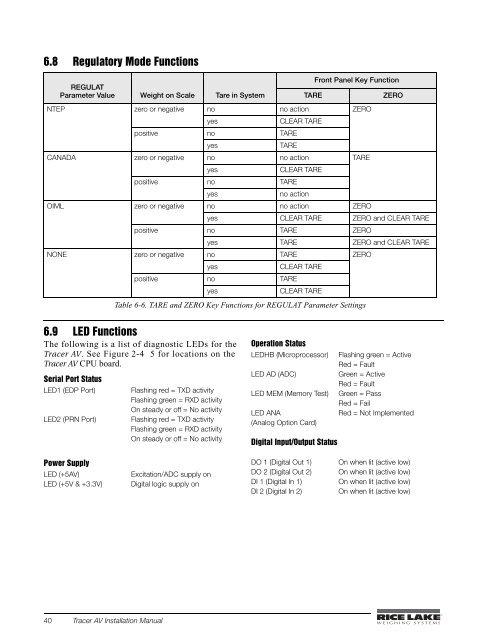
6.8 Regulatory Mode FunctionsREGULATParameter Value Weight on Scale Tare in SystemTAREFront Panel Key FunctionZERONTEP zero or negative no no action ZEROyesCLEAR TAREpositive no TAREyesTARECANADA zero or negative no no action TAREyesCLEAR TAREpositive no TAREyesno actionOIML zero or negative no no action ZEROyes CLEAR TARE ZERO and CLEAR TAREpositive no TARE ZEROyes TARE ZERO and CLEAR TARENONE zero or negative no TARE ZEROyesCLEAR TAREpositive no TAREyesCLEAR TARETable 6-6. TARE and ZERO Key Functions for REGULAT Parameter Settings6.9 LED FunctionsThe following is a list of diagnostic LEDs for the<strong>Tracer</strong> <strong>AV</strong>. See Figure 2-4 5 for locations on the<strong>Tracer</strong> <strong>AV</strong> CPU board.Serial Port StatusLED1 (EDP Port)LED2 (PRN Port)Flashing red = TXD activityFlashing green = RXD activityOn steady or off = No activityFlashing red = TXD activityFlashing green = RXD activityOn steady or off = No activityOperation StatusLEDHB (Microprocessor) Flashing green = ActiveRed = FaultLED AD (ADC)Green = ActiveRed = FaultLED MEM (Memory Test) Green = PassRed = FailLED ANARed = Not Implemented(Analog Option Card)Digital Input/Output StatusPower SupplyLED (+5<strong>AV</strong>)LED (+5V & +3.3V)Excitation/ADC supply onDigital logic supply onDO 1 (Digital Out 1)DO 2 (Digital Out 2)DI 1 (Digital In 1)DI 2 (Digital In 2)On when lit (active low)On when lit (active low)On when lit (active low)On when lit (active low)40 <strong>Tracer</strong> <strong>AV</strong> <strong>Installation</strong> <strong>Manual</strong>
6.10 SpecificationsPowerLine VoltagesFrequencyPower ConsumptionFusing115 or 230 VAC50 or 60 Hz1.5 A @ 115 VAC (8W)0.75 A @ 230 VAC (8W)2.5 A 5 x 20 mm fuseAnalog SpecificationsFull Scale Input Signal Up to 22.5 mVExcitation Voltage +5V single sided8 x 350 or 16 x 700 load cellsSense Amplifier Differential amplifier with4- and 6-wire sensingAnalog SignalInput Range –0.5 mV/V to +4.5 mV/VAnalog SignalSensitivity 0.3 V/graduation minimum,1.5 V/grad recommendedInput Impedance 200 M, typicalNoise (ref to input) 0.3 V p-p with digital filters at 4-4-4Internal Resolution 8,000,000 countsDisplay Resolution 100 000 ddMeasurement Rate Up to 60 measurements/secInput Sensitivity 10 nV per internal countSystem Linearity Within 0.01% of full scaleZero Stability 150 nV/°C, maximumSpan Stability 3.5 ppm/°C, maximumCalibration Method Software, constants stored inEEPROMCommon ModeVoltage –2.35 to +3.45 V, referred to groundRejection 130 dB minimum @ 50 or 60 HzNormal ModeRejection 90 dB minimum @ 50 or 60 HzInput Overload ± 12 V continuous, static dischargeprotectedRFI Protection Signal, excitation, and sense linesprotected by capacitor bypassAnalog Output Optional: fully isolated, voltage orcurrent output,14-bit resolution.Voltage output: 0 –10 VDCLoad resistance:1K minimumCurrent output: 0–20/4–20 mAExternal loop resistance: 500maximumDigital SpecificationsMicrocomputer Phillips PXAG30K main processor @19.6608 MHzDigital Inputs 2 inputs, TTL or switch closure,active-lowDigital Outputs 2 outputs, 250 mA Max SinkDigital Filters 3 filters, software selectableSerial CommunicationsEDP PortFull duplex RS-232Printer PortFull duplex RS-232 or active transmitonly 20 mA current loopBoth Ports 38400, 19200, 9600, 4800, 2400,1200, 600, 300 bps; 7 or 8 data bits;even, odd, or no parityOperator InterfaceDisplayLED annunciatorsKeypad6-digit LED display. 7-segment, 1.8 in(44.5 mm) digitsGross, net, center of zero, standstill,lb/primary units, kg/secondary units,count, tare2-button keypadEnvironmentalOperating Temperature–10 to +40°C (legal);–10 to +50°C (industrial)Storage Temperature –25 to +70°CHumidity0–95% relative humidityEnclosureEnclosure Dimensions 10.5 in x 12.5 in x 6.4 in26.7 cm x 31.75 cm x 16.3 cmWeight7.8 lb. (3.54 Kg)Rating/Material UL Type 1<strong>Tracer</strong> <strong>AV</strong> <strong>Installation</strong> <strong>Manual</strong> - Appendix 41