

Tracer AV Installation Manual - Rice Lake Weighing Systems
Tracer AV Installation Manual - Rice Lake Weighing Systems
Tracer AV Installation Manual - Rice Lake Weighing Systems

Create successful ePaper yourself
Turn your PDF publications into a flip-book with our unique Google optimized e-Paper software.
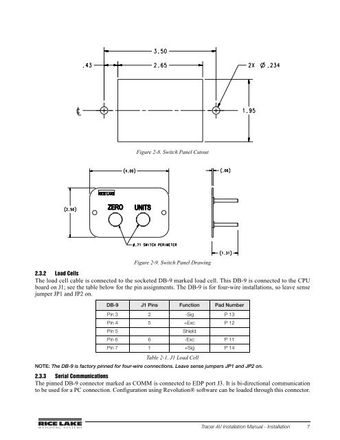
Figure 2-8. Switch Panel CutoutFigure 2-9. Switch Panel Drawing2.3.2 Load CellsThe load cell cable is connected to the socketed DB-9 marked load cell. This DB-9 is connected to the CPUboard on J1; see the table below for the pin assignments. The DB-9 is for four-wire installations, so leave sensejumper JP1 and JP2 on.DB-9 J1 Pins Function Pad NumberPin 3 2 -Sig P 13Pin 4 5 +Exc P 12Pin 5ShieldPin 6 6 -Exc P 11Pin 7 1 +Sig P 14Table 2-1. J1 Load CellNOTE: The DB-9 is factory pinned for four-wire connections. Leave sense jumpers JP1 and JP2 on.2.3.3 Serial CommunicationsThe pinned DB-9 connector marked as COMM is connected to EDP port J3. It is bi-directional communicationto be used for a PC connection. Configuration using Revolution® software can be loaded through this connector.<strong>Tracer</strong> <strong>AV</strong> <strong>Installation</strong> <strong>Manual</strong> - <strong>Installation</strong> 7


