

Tracer AV Installation Manual - Rice Lake Weighing Systems
Tracer AV Installation Manual - Rice Lake Weighing Systems
Tracer AV Installation Manual - Rice Lake Weighing Systems

Create successful ePaper yourself
Turn your PDF publications into a flip-book with our unique Google optimized e-Paper software.
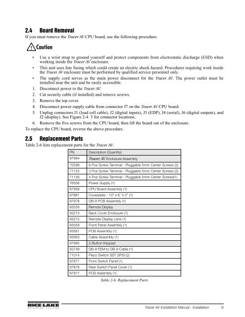
2.4 Board RemovalIf you must remove the <strong>Tracer</strong> <strong>AV</strong> CPU board, use the following procedure:• Use a wrist strap to ground yourself and protect components from electrostatic discharge (ESD) whenworking inside the <strong>Tracer</strong> <strong>AV</strong> enclosure.• This unit uses line fusing which could create an electric shock hazard. Procedures requiring work insidethe <strong>Tracer</strong> <strong>AV</strong> enclosure must be performed by qualified service personnel only.• The supply cord serves as the main power disconnect for the <strong>Tracer</strong> <strong>AV</strong>. The power outlet must beinstalled near the unit and be easily accessible.1. Disconnect power to the <strong>Tracer</strong> <strong>AV</strong>.2. Cut security cable (if installed) and remove screws.3. Remove the top cover.4. Disconnect power supply cable from connector J7 on the <strong>Tracer</strong> <strong>AV</strong> CPU board.5. Unplug connectors J1 (load cell cable), J2 (digital inputs), J3 (EDP), J4 (serial), J6 (digital outputs), andJ2 (display). See Figure 2-4 5 for connector locations.6. Remove the five screws from the CPU board, then lift the board out of the enclosure.To replace the CPU board, reverse the above procedure.2.5 Replacement PartsTable 2-6 lists replacement parts for the <strong>Tracer</strong> <strong>AV</strong>.PN Description (Quantity)97994 <strong>Tracer</strong> <strong>AV</strong> Enclosure Assembly70599 6 Pos Screw Terminal - Pluggable 5mm Center Screws (2)71125 3 Pos Screw Terminal - Pluggable 5mm Center Screws (2)71126 4 Pos Screw Terminal - Pluggable 5mm Center Screws(1)76556 Power Supply (1)87958 CPU Board Assembly (1)97881 Coverplate - 10” x 6 ”x 2” (1)97978 DB-9 PCB Assembly (1)93558 Remote Display93213 Back Cover Enclosure (1)93215 Remote Display Lens (1)93559 Front Panel Assembly (1)93561 PCB Assembly (1)93563 Cable Assembly (1)97995 2-Button Keypad50749 DB-9 FEM to DB-9 Cable (1)71014 Piezo Switch SST SPSI (2)97877 Front Switch Panel (1)97878 Rear Switch Panel Cover (1)97977 PCB Assembly (1)Table 2-6. Replacement Parts<strong>Tracer</strong> <strong>AV</strong> <strong>Installation</strong> <strong>Manual</strong> - <strong>Installation</strong> 9


