

ISHIDA BC-3000 Scale to Scale Communications - Rice Lake ...
ISHIDA BC-3000 Scale to Scale Communications - Rice Lake ...
ISHIDA BC-3000 Scale to Scale Communications - Rice Lake ...

Create successful ePaper yourself
Turn your PDF publications into a flip-book with our unique Google optimized e-Paper software.
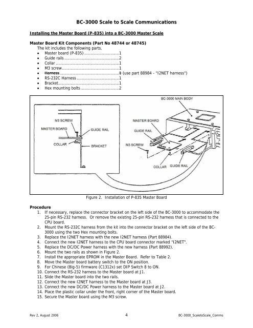
<strong>BC</strong>-<strong>3000</strong> <strong>Scale</strong> <strong>to</strong> <strong>Scale</strong> <strong>Communications</strong>Installing the Master Board (P-835) in<strong>to</strong> a <strong>BC</strong>-<strong>3000</strong> Master <strong>Scale</strong>Master Board Kit Components (Part No 48744 or 48745)The kit includes the following parts.• Master board (P-835) ............................1• Guide rails ............................................2• Collar ...................................................1• M3 screw..............................................1• Harness................................................1 (use part 88984 - "I2NET harness")• RS-232C Harness ..................................1• Bracket.................................................1• Hex mounting bolts ...............................2Figure 2. Installation of P-835 Master BoardProcedure1. If necessary, replace the connec<strong>to</strong>r bracket on the left side of the <strong>BC</strong>-<strong>3000</strong> <strong>to</strong> accommodate the25-pin RS-232 harness. Or remove the existing 25-pin RS-232 harness that is connected <strong>to</strong> theCPU board.2. Mount the RS-232C harness from the kit in<strong>to</strong> the connec<strong>to</strong>r bracket on the left side of the <strong>BC</strong>-<strong>3000</strong> using the two Hex mounting bolts.3. Replace the I2NET harness with the new I2NET harness (Part 88984).4. Connect the new I2NET harness <strong>to</strong> the CPU board connec<strong>to</strong>r marked "I2NET".5. Replace the DC/DC Power harness with the new harness (Part 88992).6. Mount the two rails as shown in Figure 2.7. Install the appropriate EPROM in the Master Board. Refer <strong>to</strong> Table 2.8. Move the Master board battery switch <strong>to</strong> the ON position.9. For Chinese (Big-5) firmware (C1312x) set DIP Switch 8 <strong>to</strong> ON.10. Connect the RS-232 harness <strong>to</strong> the Master board at J1.11. Slide the Master board in<strong>to</strong> the two rails.12. Connect the new I2NET harness <strong>to</strong> the Master board at J3.13. Connect the new DC/DC Power harness <strong>to</strong> the Master board at J2.14. Place the plastic collar under the front, right corner of the Master board.15. Secure the Master board using the M3 screw.Rev 2, August 2006 4 <strong>BC</strong>-<strong>3000</strong>_<strong>Scale</strong><strong>to</strong><strong>Scale</strong>_Comms


