MGP - SMC
MGP - SMC
MGP - SMC

You also want an ePaper? Increase the reach of your titles
YUMPU automatically turns print PDFs into web optimized ePapers that Google loves.
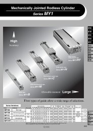
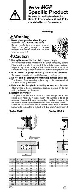
Series <strong>MGP</strong><br />
Model Selection<br />
Selection Conditions<br />
Vertical<br />
Horizontal<br />
l<br />
l<br />
l<br />
l<br />
m<br />
m<br />
Mounting orientation<br />
m<br />
m<br />
Maximum speed (mm/s)<br />
200 or less<br />
400<br />
200 or less<br />
400<br />
Graph (Slide bearing type)<br />
(1), (2)<br />
(3), (4)<br />
(13), (14)<br />
(15), (16)<br />
Graph (Ball bushing bearing type)<br />
(5) to (8)<br />
(9) to (12)<br />
(17), (18)<br />
(19), (20)<br />
Selection Example 1 (Vertical Mounting)<br />
Selection Example 2 (Horizontal Mounting)<br />
Selection conditions<br />
Mounting: Vertical<br />
Bearing type: Ball bushing<br />
Stroke: 30 stroke<br />
Maximum speed: 200 mm/s<br />
Load mass: 3 kg<br />
Eccentric distance: 90 mm<br />
Find the point of intersection for the load mass of 3 kg and the eccentric<br />
distance of 90 mm on graph (5), based on vertical mounting, ball bushing,<br />
30 stroke, and the speed of 200 mm/s.<br />
<strong>MGP</strong>L25-30 is selected.<br />
(5) Less than 40 stroke, V = 200 mm/s or less (13) l = 50 mm, V = 200 mm/s or less<br />
Load mass m (kg)<br />
20<br />
10<br />
5<br />
1<br />
ø25<br />
ø20<br />
ø16<br />
ø12<br />
Selection conditions<br />
Mounting: Horizontal<br />
Bearing type: Slide bearing<br />
Distance between plate and load center of gravity: 50 mm<br />
Maximum speed: 200 mm/s<br />
Load mass: 2 kg<br />
Stroke: 30 stroke<br />
Find the point of intersection for the load mass of 2 kg and 30 stroke on<br />
graph (13), based on horizontal mounting, slide bearing, the distance of 50 mm<br />
between the plate and load center of gravity, and the speed of 200 mm/s.<br />
<strong>MGP</strong>M20-30 is selected.<br />
Load mass m (kg)<br />
50 ø100<br />
10<br />
5<br />
1<br />
ø80<br />
ø50,63<br />
ø32,40<br />
ø25<br />
ø20<br />
ø16<br />
ø12<br />
ø100<br />
ø80<br />
ø50,63<br />
ø32,40<br />
ø25<br />
ø20<br />
ø16<br />
ø12<br />
MGJ<br />
<strong>MGP</strong><br />
MGQ<br />
MGG<br />
MGC<br />
MGF<br />
MGZ<br />
MGT<br />
0.1<br />
10 50 100 200<br />
0.1<br />
10 20 30 40 50 51 100 200 300<br />
Eccentric distance l (mm)<br />
Stroke (mm)<br />
. When the maximum speed exceeds 200 mm/s, the allowable load mass is determined by multiplying the value shown in the graph at 400 mm/s<br />
by the coefficient listed in the table below.<br />
Maximum<br />
Coefficient<br />
Up to 300 mm/s<br />
1.7<br />
Up to 400 mm/s<br />
1<br />
Up to 500 mm/s<br />
0.6<br />
D-<br />
-X<br />
Individual<br />
-X<br />
275