MGP - SMC
MGP - SMC
MGP - SMC

You also want an ePaper? Increase the reach of your titles
YUMPU automatically turns print PDFs into web optimized ePapers that Google loves.
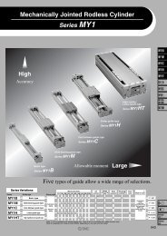
Compact Guide Cylinder<br />
With End Lock<br />
Series <strong>MGP</strong><br />
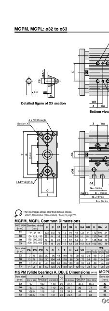
Specifications<br />
Bore size<br />
Action<br />
Fluid<br />
Proof pressure<br />
Maximum operating pressure<br />
Minimum operating pressure<br />
Ambient and fluid temperature<br />
Piston speed<br />
Cushion<br />
Lubrication<br />
Stroke length tolerance<br />
∗ 0.1 MPa except the lock unit.<br />
Lock Specifications<br />
ø20 ø25 ø32 ø40 ø50 ø63 ø80 ø100<br />
Double acting<br />
Air<br />
1.5 MPa<br />
1.0 MPa<br />
0.15 MPa ∗<br />
–10 to 60°C (No freezing)<br />
50 to 500 mm/s<br />
50 to 400 mm/s<br />
Rubber bumper on both ends<br />
Not required (Non-lube)<br />
+1.5<br />
0 mm<br />
Symbol<br />
Made to Order Specifications<br />
(For details, refer to pages 1847 and 1995.)<br />
Specifications<br />
—XC79 Machining tapped hole, drilled hole and pin hole additionally.<br />
—X867 Lateral piping type (Change of plug position)<br />
Refer to pages 334 to 336 for cylinders<br />
with auto switches.<br />
<br />
Minimum auto switch mounting stroke<br />
<br />
Proper auto switch mounting position<br />
(detection at stroke end) and mounting height<br />
<br />
Operating range<br />
<br />
Switch mounting bracket: Part no.<br />
Lock position<br />
Holding force<br />
(Max.) N<br />
Backlash<br />
Manual release<br />
Adjust switch positions for operation at both the stroke end and backlash (2 mm) movement positions.<br />
Standard Stroke<br />
Bore size (mm)<br />
20, 25, 32, 40,<br />
50, 63, 80, 100<br />
ø20<br />
215<br />
Theoretical Output<br />
ø25<br />
330<br />
ø32<br />
550<br />
Head end, Rod end<br />
ø40 ø50<br />
860 1340<br />
2 mm or less<br />
Non-lock type, Lock type<br />
Standard stroke (mm)<br />
25, 50, 75, 100, 125, 150, 175, 200, 250, 300, 350, 400<br />
Manufacture of Intermediate Stroke<br />
(N)<br />
Bore size Rod size Operating Piston area<br />
Operating pressure (MPa)<br />
(mm) (mm) direction (mm 2 ) 0.2 0.3 0.4 0.5 0.6 0.7 0.8 0.9 1.0<br />
20 10<br />
OUT 314 63 94 126 157 188 220 251 283 314<br />
IN 236 47 71 94 118 142 165 189 212 236<br />
25 12<br />
OUT 491 98 147 196 246 295 344 393 442 491<br />
IN 378 76 113 151 189 227 265 302 340 378<br />
32 16<br />
OUT 804 161 241 322 402 482 563 643 724 804<br />
IN 603 121 181 241 302 362 422 482 543 603<br />
40 16<br />
OUT 1257 251 377 503 629 754 880 1006 1131 1257<br />
IN 1056 211 317 422 528 634 739 845 950 1056<br />
50 20<br />
OUT 1963 393 589 785 982 1178 1374 1570 1767 1963<br />
IN 1649 330 495 660 825 990 1154 1319 1484 1649<br />
63 20<br />
OUT 3117 623 935 1247 1559 1870 2182 2494 2805 3117<br />
IN 2803 561 841 1121 1402 1682 1962 2242 2523 2803<br />
80 25<br />
OUT 5027 1005 1508 2011 2514 3016 3519 4022 4524 5027<br />
IN 4536 907 1361 1814 2268 2722 3175 3629 4082 4536<br />
100 30<br />
OUT 7854 1571 2356 3142 3927 4712 5498 6283 7069 7854<br />
IN 7147 1429 2144 2859 3574 4288 5003 5718 6432 7147<br />
Note) Theoretical output (N) = Pressure (MPa) x Piston area (mm 2 )<br />
OUT<br />
ø63<br />
2140<br />
ø80<br />
3450<br />
IN<br />
ø100<br />
5390<br />
Spacer installation type.<br />
Dealing with the stroke by the 5 mm interval is available by installing spacer with<br />
Description<br />
standard stroke cylinder. When a spacer is mounted on the cylinder with an end<br />
lock on the rod side, use a special piston rod.<br />
Part no. Refer to “How to Order” for the standard model numbers on page 308.<br />
Applicable stroke (mm)<br />
5 to 395<br />
Example Part no.: <strong>MGP</strong>M50-35-HN<br />
A spacer 15 mm in width is installed in a <strong>MGP</strong>M50-50-HN. C dimension is 119 mm.<br />
Note 1) The minimum stroke for mounting auto switches is 10 stroke or more for two switches, and 5 stroke or more for one switch.<br />
Note 2) Intermediate stroke (by the 1 mm interval) based on an exclusive body will be available upon request for special.<br />
309<br />
MGJ<br />
<strong>MGP</strong><br />
MGQ<br />
MGG<br />
MGC<br />
MGF<br />
MGZ<br />
MGT<br />
D-<br />
-X<br />
Individual<br />
-X