Configuration of ACK Trees for Multicast Transport ... - ETRI Journal
Configuration of ACK Trees for Multicast Transport ... - ETRI Journal
Configuration of ACK Trees for Multicast Transport ... - ETRI Journal

You also want an ePaper? Increase the reach of your titles
YUMPU automatically turns print PDFs into web optimized ePapers that Google loves.
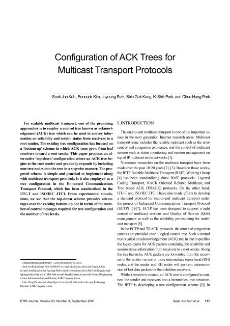
<strong>Configuration</strong> <strong>of</strong> <strong>ACK</strong> <strong>Trees</strong> <strong>for</strong><br />
<strong>Multicast</strong> <strong>Transport</strong> Protocols<br />
Seok Joo Koh, Eunsook Kim, Juyoung Park, Shin Gak Kang, Ki Shik Park, and Chee Hang Park<br />
For scalable multicast transport, one <strong>of</strong> the promising<br />
approaches is to employ a control tree known as acknowledgement<br />
(<strong>ACK</strong>) tree which can be used to convey in<strong>for</strong>mation<br />
on reliability and session status from receivers to a<br />
root sender. The existing tree configuration has focused on<br />
a ‘bottom-up’ scheme in which <strong>ACK</strong> trees grow from leaf<br />
receivers toward a root sender. This paper proposes an alternative<br />
‘top-down’ configuration where an <strong>ACK</strong> tree begins<br />
at the root sender and gradually expands by including<br />
non-tree nodes into the tree in a stepwise manner. The proposed<br />
scheme is simple and practical to implement along<br />
with multicast transport protocols. It is also employed as a<br />
tree configuration in the Enhanced Communications<br />
<strong>Transport</strong> Protocol, which has been standardized in the<br />
ITU-T and ISO/IEC JTC1. From experimental simulations,<br />
we see that the top-down scheme provides advantages<br />
over the existing bottom-up one in terms <strong>of</strong> the number<br />
<strong>of</strong> control messages required <strong>for</strong> tree configuration and<br />
the number <strong>of</strong> tree levels.<br />
Manuscript received February 7, 2001; revised July 31, 2001.<br />
Seok Joo Koh (phone: +82 42 860 6218, e-mail: sjkoh@pec.etri.re.kr), Eunsook Kim<br />
(e-mail: eunah@etri.re.kr), Juyoung Park (e-mail: jypark@etri.re.kr), Shin Gak Kang (e-mail:<br />
sgkang@etri.re.kr), and Ki Shik Park (e-mail: kipark@etri.re.kr) are with Protocol Engineering<br />
Center, In<strong>for</strong>mation Support Division, <strong>ETRI</strong>, Daejeon, Korea.<br />
Chee Hang Park (e-mail: chpark@etri.re.kr) is with In<strong>for</strong>mation Security Technology<br />
Division, <strong>ETRI</strong>, Daejeon, Korea<br />
I. INTRODUCTION<br />
The end-to-end multicast transport is one <strong>of</strong> the important issues<br />
in the next generation Internet research areas. <strong>Multicast</strong><br />
transport issue includes the reliable multicast such as the error<br />
control and congestion avoidance, and the control <strong>of</strong> multicast<br />
session such as status monitoring and session management on<br />
top <strong>of</strong> IP multicast in the networks [1].<br />
Numerous researches on the multicast transport have been<br />
made over the past 10-20 years [2], [3]. Based on those works,<br />
the IETF Reliable <strong>Multicast</strong> <strong>Transport</strong> (RMT) Working Group<br />
[4] has been standardizing three RMT protocols: Layered<br />
Coding <strong>Transport</strong>, N<strong>ACK</strong> Oriented Reliable <strong>Multicast</strong>, and<br />
Tree based <strong>ACK</strong> (TR<strong>ACK</strong>) protocols. On the other hand,<br />
ITU-T and ISO/IEC JTC 1 have also made ef<strong>for</strong>ts to develop<br />
a standard protocol <strong>for</strong> end-to-end multicast transport under<br />
the project <strong>of</strong> Enhanced Communications <strong>Transport</strong> Protocol<br />
(ECTP) [5]-[7]. ECTP has been designed to support a tight<br />
control <strong>of</strong> multicast sessions and Quality <strong>of</strong> Service (QoS)<br />
management as well as the reliability provisioning <strong>for</strong> multicast<br />
transport [8].<br />
In the ECTP and TR<strong>ACK</strong> protocols, the error and congestion<br />
controls are provided over a logical control tree. Such a control<br />
tree is called an acknowledgement (<strong>ACK</strong>) tree in that it specifies<br />
the logical paths <strong>for</strong> <strong>ACK</strong> packets containing the reliability and<br />
session status in<strong>for</strong>mation from receivers to a root sender. Along<br />
the tree hierarchy, <strong>ACK</strong> packets are <strong>for</strong>warded from the receivers<br />
to the sender via one or more intermediate repair head (RH)<br />
nodes, and the sender and RH nodes will per<strong>for</strong>m retransmission<br />
<strong>of</strong> lost data packets <strong>for</strong> their children receivers.<br />
While a session is created, an <strong>ACK</strong> tree is configured to connect<br />
the sender and receivers into a hierarchical tree structure.<br />
The IETF is developing a tree configuration scheme [9], in<br />
<strong>ETRI</strong> <strong>Journal</strong>, Volume 23, Number 3, September 2001 Seok Joo Koh et al. 111
which an <strong>ACK</strong> tree is automatically constructed by interactions<br />
between sender and receivers. This scheme is called a ‘bottomup’<br />
approach taking the viewpoint that the <strong>ACK</strong> tree construction<br />
process starts from the leaf receivers, and the tree gradually<br />
grows toward the root sender. The related work or its variants<br />
can be referred to in the literatures [10], [11].<br />
The bottom-up approach <strong>for</strong> tree configuration may give<br />
some benefits in terms <strong>of</strong> the tree optimization, but it also involves<br />
the following drawbacks:<br />
• a deeper tree with many tree levels<br />
The bottom-up scheme is inclined to generate a deep tree<br />
with many tree levels since all the nodes try to find the nearest<br />
parent nodes without any consideration <strong>of</strong> the configured tree<br />
levels. Note that many tree levels are not desirable <strong>for</strong> the stable<br />
operation <strong>of</strong> the tree-based reliability mechanisms. For example,<br />
the delivery <strong>of</strong> the error and congestion status in<strong>for</strong>mation<br />
from the leaf receivers to the root sender will be more delayed<br />
in a deeper tree due to the frequent <strong>ACK</strong> aggregations at the intermediate<br />
RH nodes.<br />
• more control messages required <strong>for</strong> tree configuration<br />
The bottom-up scheme based on the Expanding Ring Search<br />
(ERS) may generate more optimized trees in terms <strong>of</strong> the timeto-live<br />
(TTL) hop distances. It is noted, however, that such optimal<br />
trees are obtained at the cost <strong>of</strong> more control messages <strong>for</strong><br />
the tree configuration. More control messages require more<br />
network bandwidths.<br />
In addition to these drawbacks, the bottom-up scheme cannot<br />
guarantee a loop-free tree configuration. To provide a loopfree<br />
<strong>ACK</strong> tree, an additional metric such as distance from the<br />
sender must be en<strong>for</strong>ced along with an appropriate activation<br />
rule [11]. In particular, the ERS-based scheme depends on the<br />
multicast transmission capability <strong>of</strong> end receivers, while the recently<br />
focused multicast routing protocol such as Source Specific<br />
<strong>Multicast</strong> [12] excludes such assumption.<br />
In this paper, we propose an alternative top-down tree<br />
configuration [13], in which, only the on-tree RH nodes are<br />
allowed to accept children, but an <strong>of</strong>f-tree RH is prohibited<br />
to have its children. Thus, an <strong>ACK</strong> tree will grow from the<br />
root sender toward the leaf receivers by including the nontree<br />
nodes in a stepwise manner. The proposed top-down<br />
scheme generates a lower-level tree with less control messages.<br />
The proposed scheme also provides a loop-free tree<br />
intrinsically.<br />
The underlying idea <strong>for</strong> tree configuration is simple but practical<br />
in the viewpoint <strong>of</strong> the design <strong>of</strong> a realistic multicast transport<br />
protocol. In particular, the proposed tree configuration will<br />
be preferred by multicast sessions that require the senderinitiated<br />
tight control <strong>of</strong> overall tree <strong>for</strong> billing and security<br />
purposes, as described in ECTP.<br />
This paper is organized as follows. Section II introduces the<br />
ECTP protocol as an example standard protocol <strong>for</strong> multicast<br />
transport, along with tree-based reliability mechanisms. In Section<br />
III, the existing ERS-based bottom-up scheme is summarized<br />
more in detail. The proposed top-down scheme is described<br />
and compared with the bottom-up one in Section IV.<br />
Section V shows the experimental results <strong>for</strong> the evaluation <strong>of</strong><br />
the proposed scheme under a variety <strong>of</strong> test environments. In<br />
Section VI, we conclude this paper.<br />
II. A MULTICAST TRANSPORT PROTOCOL:<br />
ECTP<br />
This section introduces the ECTP protocol, which is a standard<br />
protocol <strong>for</strong> multicast transport based on <strong>ACK</strong> tree [5], [6].<br />
The ECTP is a transport protocol designed to support Internet<br />
multicast applications. ECTP operates over IPv4/IPv6 networks<br />
that have IP multicast <strong>for</strong>warding capability. Figure 1<br />
shows an overview <strong>of</strong> the ECTP operations.<br />
Be<strong>for</strong>e an ECTP transport connection is created, the prospective<br />
receivers are enrolled into the multicast group. Such a<br />
group is called an enrolled group. During enrollment, authentication<br />
processes may be per<strong>for</strong>med together with group key<br />
distribution.<br />
ECTP<br />
Connection<br />
Lifetime<br />
Connection Creation<br />
Control Tree Creation<br />
QoS Negotiation<br />
<strong>Multicast</strong> Data Transfer<br />
Tree-based Reliability Control<br />
Tree Membership Maintenance<br />
Late Join and Leave<br />
QoS Monitoring<br />
QoS Maintenance<br />
Connection Termination<br />
Fig. 1. ECTP protocol operations.<br />
112 Seok Joo Koh et al. <strong>ETRI</strong> <strong>Journal</strong>, Volume 23, Number 3, September 2001
The IP multicast addresses and port numbers must be announced<br />
to the receivers. These enrollment operations may rely<br />
on the web page announcement.<br />
An enrolled receiver will be connected to the multicastcapable<br />
network with the help <strong>of</strong> the IP multicast routing protocols.<br />
Those multicast routing protocols will refer to the announced<br />
multicast addresses. An ECTP transport connection<br />
will be created <strong>for</strong> the enrolled receivers.<br />
ECTP is designed to support tightly controlled multicast<br />
connections. ECTP sender is at the heart <strong>of</strong> the multicast group<br />
communication. The sender is responsible <strong>for</strong> the overall management<br />
<strong>of</strong> the connection by governing connection creation<br />
and termination, and the late join and leave operations.<br />
The ECTP sender triggers the connection creation process by<br />
sending a connection creation message. Each enrolled receiver<br />
responds with a confirmation message to the sender. The connection<br />
creation is completed when the sender receives the<br />
confirmation messages from all <strong>of</strong> the active receivers, or when<br />
the pre-specified timer expires. QoS negotiation may be per<strong>for</strong>med<br />
in the connection creation [7].<br />
Throughout the connection creation, some or all <strong>of</strong> the enrolled<br />
group receivers will join the connection. The receivers<br />
that have joined the connection are called active receivers. An<br />
enrolled receiver that is not active can participate in the connection<br />
as a late-joiner. The late-joiner sends a join request to the<br />
sender. In response to the join request, the sender transmits a<br />
join confirm message, which indicates whether the join request<br />
is accepted or not. An active receiver can leave the connection<br />
by sending a leave request to the sender.<br />
After a connection is created, the sender begins to transmit<br />
multicast data. For data transmission, an application data<br />
stream is sequentially segmented and transmitted by means <strong>of</strong><br />
data packets to the receivers. The receivers will deliver the received<br />
data packets to the applications in the order transmitted.<br />
To make the protocol scalable to large multicast groups,<br />
ECTP employs the tree-based reliability control mechanisms. A<br />
hierarchical tree is configured during connection creation. A<br />
control tree defines a parent-child relationship between any two<br />
tree nodes comprising a pair. The sender is the root <strong>of</strong> the control<br />
tree. Each local group is defined along the tree hierarchy. A<br />
local group consists <strong>of</strong> a parent and zero or more children. The<br />
error, flow and congestion controls are per<strong>for</strong>med <strong>for</strong> each local<br />
group defined by the control tree. Figure 2 illustrates an<br />
<strong>ACK</strong> tree hierarchy <strong>for</strong> reliability control, in which each node<br />
represents a sender (S), a receiver (R), or repair head (RH). In<br />
the tree creation, a control tree is gradually expanded from the<br />
sender to the receivers. There<strong>for</strong>e, it is called a top-down configuration.<br />
ECTP has also adopted a bottom-up approach standardized<br />
in IETF [9].<br />
<strong>ACK</strong><br />
S<br />
<strong>Multicast</strong> Data<br />
Transmission<br />
RH RH RH<br />
R R R R R R R R R<br />
Fig. 2. <strong>ACK</strong> tree <strong>for</strong> reliability control.<br />
In ECTP, error control is per<strong>for</strong>med <strong>for</strong> each local group defined<br />
by a control tree. If a child detects a data loss, it sends a<br />
retransmission request to its parent via <strong>ACK</strong> packets. An <strong>ACK</strong><br />
message contains the in<strong>for</strong>mation that identifies the data packets<br />
successfully received. Each child can send an <strong>ACK</strong> message<br />
to its parent using one <strong>of</strong> the two <strong>ACK</strong> generation rules:<br />
<strong>ACK</strong> number and <strong>ACK</strong> timer. If data traffic is high, an <strong>ACK</strong> is<br />
generated <strong>for</strong> the <strong>ACK</strong> number <strong>of</strong> data packets. If the traffic is<br />
low, an <strong>ACK</strong> message will be transmitted after the <strong>ACK</strong> timer<br />
expires. After retransmission <strong>of</strong> data, the parent activates a retransmission<br />
back-<strong>of</strong>f timer. During the time interval, the retransmission<br />
request(s) <strong>for</strong> the same data will be ignored. Each<br />
parent can remove the data acknowledged by all <strong>of</strong> its children<br />
from its buffer memory.<br />
Tree-membership is maintained during the connection. A<br />
late-joiner is allowed to join the control tree. The late-joiner listens<br />
to the heartbeat messages from one or more on-tree parents<br />
and then joins the best parent. When a child leaves the<br />
connection, the parent removes the departing child from the<br />
children-list. Node failures are detected by using periodic control<br />
messages such as null data, heartbeat and acknowledgement.<br />
The sender transmits periodic null data messages to indicate<br />
that it is alive, even if it has no data to transmit. Each parent<br />
periodically sends heartbeat messages to its children. On<br />
the other hand, each child transmits periodic acknowledgement<br />
messages to its parent.<br />
During the data transmission, if severe network congestion is<br />
indicated, the sender suspends the multicast data transmission<br />
temporarily. In this period, no new data is delivered, while the<br />
sender transmits periodic null data messages to indicate that it<br />
is alive. After a pre-specified time, the sender resumes the multicast<br />
data transmission.<br />
After an ECTP connection is created, QoS monitoring and<br />
maintenance operations are per<strong>for</strong>med <strong>for</strong> the multicast data<br />
transmission [7]. For QoS monitoring, each receiver is required<br />
to measure the parameter values experienced. Based on the<br />
measured values, a receiver determines a parameter status value<br />
<strong>ETRI</strong> <strong>Journal</strong>, Volume 23, Number 3, September 2001 Seok Joo Koh et al. 113
<strong>for</strong> each parameter. These status values will be delivered to the<br />
sender via <strong>ACK</strong> packets. Sender aggregates the parameter status<br />
values reported from receivers. If a control tree is employed,<br />
each parent RH node aggregates the measured values reported<br />
from its children and <strong>for</strong>wards the aggregated values to its parent<br />
via its <strong>ACK</strong> packets.<br />
The sender takes QoS maintenance actions necessary to<br />
maintain the connection status at a desired QoS level, based on<br />
the monitored status values. Specific rules are pre-configured to<br />
trigger QoS maintenance actions such as data transmission rate<br />
adjustment, connection pause and resume, and connection termination.<br />
Those rules are based on observation that how many<br />
receivers are in the abnormal or possibly abnormal status.<br />
The sender terminates the connection by sending a termination<br />
message to all the receivers after all the multicast data are<br />
transmitted. The connection may also terminate due to a fatal<br />
protocol error such as connection failure.<br />
III. BOTTOM-UP TREE CONFIGURATION<br />
The tree configuration currently proposed in IETF [9] can be<br />
considered as a bottom-up approach from the viewpoint that all<br />
the leaf receivers try to find their parent RH nodes in parallel<br />
and the tree is expanded from the leaf receivers toward the root<br />
sender.<br />
A generic tree configuration proceeds in the order <strong>of</strong> session<br />
advertisement, RH discovery, and binding to the best RH. In<br />
the session advertisement, each receiver realizes the existence<br />
<strong>of</strong> a session and the sender by using an out-<strong>of</strong>-band mechanism<br />
such as Web page announcement. In this way, the receiver will<br />
obtain the multicast group address and the sender’s address,<br />
and the other in<strong>for</strong>mation necessary <strong>for</strong> the <strong>ACK</strong> tree construction.<br />
When the sender indicates the creation <strong>of</strong> an <strong>ACK</strong> tree,<br />
each receiver begins the RH discovery process to find one or<br />
more candidate RH nodes that are active in the session. Among<br />
the candidate RH nodes discovered, a receiver selects and<br />
binds to the best RH node as its parent by using a preconfigured<br />
rule such as TTL distance or IP address.<br />
Depending on the RH discovery mechanism employed, the<br />
detailed tree configuration procedures are slightly different from<br />
each other. In [9], three different RH discovery mechanisms are<br />
provided: point <strong>of</strong> contact (POC) based, generic router assist<br />
(GRA) based and expanding ring search (ERS) based.<br />
A POC is a dedicated server that is established <strong>for</strong> the <strong>ACK</strong><br />
tree construction in the network. Each RH node enrolls itself to<br />
the POC which is located in its domain. Each receiver asks the<br />
POC “which RH nodes are active in the domain.” The POC<br />
then responds to the receiver with a list <strong>of</strong> active RH nodes.<br />
The GRA approach tries to construct an <strong>ACK</strong> tree that keeps<br />
congruency with the underlying multicast routing tree topology.<br />
To do this, each GRA router collects the routing tree in<strong>for</strong>mation<br />
and delivers it to the downstream receivers <strong>for</strong> the associated<br />
multicast group.<br />
In the ERS-based scheme, a receiver discovers the RH nodes<br />
by using multicast query messages. Each receiver first asks if<br />
there is a neighboring RH node by multicast. One or more RH<br />
nodes may respond to the query message. If there is no response<br />
from RH nodes, the receiver will re-send the query<br />
messages with an increased TTL value until at least one RH<br />
node is discovered.<br />
We note that both POC and GRA schemes depend on the<br />
dedicated facilities such as POC servers or GRA routers that<br />
have been pre-configured in the network. The corresponding<br />
per<strong>for</strong>mance <strong>for</strong> the tree configuration also depends on how<br />
much those facilities are deployed. This paper thus focuses on<br />
the ERS-based scheme as a promising bottom-up tree configuration<br />
scheme.<br />
The ERS-based bottom-up tree configuration scheme is illustrated<br />
in Fig. 3, and the control messages employed <strong>for</strong> the<br />
tree configuration are summarized in Table 1.<br />
For tree configuration, the sender first indicates the tree creation<br />
by sending a session BEACON message to all the receivers<br />
and RH nodes.<br />
BIND<br />
ACCEPT<br />
BEACON<br />
QUERY<br />
BIND<br />
ADVERTISE<br />
ACCEPT or REJECT<br />
Sender Repair Head Receiver<br />
Fig. 3. ERS-based bottom-up configuration scheme.<br />
Table 1. Control messages employed <strong>for</strong> the ERS-based bottom-up<br />
configuration.<br />
Message<br />
Types From To <strong>Transport</strong> Description<br />
BEACON Sender Receivers <strong>Multicast</strong><br />
Indication <strong>of</strong> tree<br />
creation<br />
QUERY Receiver RHs <strong>Multicast</strong><br />
Finding candidate<br />
RHs<br />
ADVERTISE RH Receivers <strong>Multicast</strong> Response from RH<br />
BIND Receiver RH Unicast Bind request<br />
ACCEPT or<br />
REJECT<br />
RH Receiver Unicast<br />
Response to the bind<br />
request<br />
114 Seok Joo Koh et al. <strong>ETRI</strong> <strong>Journal</strong>, Volume 23, Number 3, September 2001
The BEACON message contains a metric, by which each RH<br />
or receiver can measure the TTL distance from the sender,<br />
which will be used to generate a loop-free <strong>ACK</strong> tree, as described<br />
later.<br />
When the tree creation is indicated, each receiver begins to<br />
find the candidate RH nodes by sending a multicast QUERY<br />
message. Some <strong>of</strong> the RH nodes may respond with a multicast<br />
ADVERTISE message. The ADVERTISE message may contain<br />
the TTL distance from the sender to the responding RH<br />
node. If there is no response from RH nodes, the receiver retransmits<br />
the QUERY message by increasing the TTL value <strong>of</strong><br />
the corresponding IP packet.<br />
Once one or more candidate RH nodes are discovered, the<br />
receiver selects the best RH node. The specific rule <strong>for</strong> the selection<br />
typically depends on the implementations. In the ERSbased<br />
scheme, the RH node with the shortest TTL distance<br />
from the sender is preferred. If a tie occurs in the TTL distance,<br />
the RH node with the lowest IP address will be chosen. It is<br />
noted that the TTL distance and the IP address can be used to<br />
guarantee the generation <strong>of</strong> a loop-free <strong>ACK</strong> tree since all the<br />
RH nodes can be distinctively arranged in the order <strong>of</strong> those<br />
two metrics.<br />
The receiver binds itself to the chosen RH by sending a<br />
BIND message, and the RH node will respond with an AC-<br />
CEPT or REJECT message. The decision <strong>of</strong> ACCEPT or RE-<br />
JECT may be made based on the tree parameters such as the<br />
maximum number <strong>of</strong> children. If a receiver receives a REJECT<br />
message, it will retry to join another RH node.<br />
When an RH node which is not on the tree has its own child,<br />
it begins the process to find its parent node. The procedural steps<br />
<strong>for</strong> parent discovery are the same as those <strong>for</strong> RH discovery. If<br />
the sender is located in the neighborhood, the RH node will bind<br />
itself to the sender without using a QUERY message. If some <strong>of</strong><br />
the receivers have failed to attach to the tree, they may join the<br />
tree as late-joiners, which is outside the scope <strong>of</strong> this paper.<br />
IV. TOP-DOWN TREE CONFIGURATION<br />
The bottom-up tree configuration seems to be effective in<br />
terms <strong>of</strong> tree optimization. However, such a scheme is inclined<br />
to generate more control messages <strong>for</strong> the tree configuration and<br />
a deeper tree with more tree levels than necessary. In this section,<br />
a top-down tree configuration scheme is proposed which aims<br />
to overcome these drawbacks <strong>of</strong> the existing approach.<br />
1. Preliminaries<br />
Depending on multicast deployment in the network, the<br />
sender and RHs may share a single IP multicast address or use<br />
different IP multicast addresses. In the networks where sender<br />
and RHs use different multicast addresses or channels, all <strong>of</strong> the<br />
multicast addresses employed must be announced to the group<br />
members be<strong>for</strong>e the <strong>ACK</strong> tree is created. In this case, one <strong>of</strong><br />
them is used <strong>for</strong> the multicast data transmission by sender, and<br />
the others are <strong>for</strong> the multicast control by RHs such as the multicast<br />
data retransmission and the multicast transmission <strong>of</strong> control<br />
messages. If a single multicast address is shared by sender<br />
and RHs, the TTL-scoped multicasting is required <strong>for</strong> each multicast<br />
traffic to restrict the multicast traffic into its local scope. In<br />
this paper, the TTL-based traffic scoping is assumed <strong>for</strong> fair<br />
comparison <strong>of</strong> the bottom-up and top-down schemes.<br />
Be<strong>for</strong>e a tree is created, every prospective group member<br />
must be attached to the network interface with the help <strong>of</strong> the<br />
IP multicast routing protocols. This ensures that the enrolled<br />
member listens to the multicast control packets from sender<br />
and RHs <strong>for</strong> tree configuration.<br />
2. Tree <strong>Configuration</strong> Mechanisms<br />
The proposed top-down scheme is similar to the existing bottom-up<br />
approach from the viewpoint that the same control<br />
messages as those used in the existing scheme are employed<br />
<strong>for</strong> the tree configuration. However, the QUERY messages<br />
from the receivers to the RH nodes are not used in the proposed<br />
scheme. The procedural steps <strong>for</strong> the tree configuration are also<br />
different from those in the bottom-up scheme.<br />
In the proposed scheme, an <strong>ACK</strong> tree gradually grows from<br />
the root sender to the receivers via one or more RH nodes.<br />
When an RH node is on the tree, it begins to find its children<br />
nodes by sending a multicast ADVERTISE messages to nontree<br />
nodes.<br />
More specifically, the top-down tree configuration steps can<br />
be summarized as follows:<br />
(A) Sender transmits a BEACON message <strong>for</strong> indication <strong>of</strong> the<br />
tree creation.<br />
(B) Some <strong>of</strong> the neighboring receivers or RH nodes join the<br />
sender by sending a BIND message. The sender responds<br />
with the corresponding ACCEPT or REJECT message.<br />
(C) When an RH node is on the tree, it begins to transmit AD-<br />
VERTISE messages to invite non-tree nodes. Each nontree<br />
receiver will collect the in<strong>for</strong>mation on the list <strong>of</strong> ontree<br />
RH nodes by receiving the ADVERTISE messages<br />
from one or more RH nodes.<br />
(D) When a non-tree RH or receiver receives one or more<br />
ADVERTISE messages, it selects the best on-tree RH node<br />
and sends a BIND message to the selected RH node.<br />
(E) The on-tree RH node determines whether the BIND request<br />
must be accepted or rejected. In the REJECT case,<br />
<strong>ETRI</strong> <strong>Journal</strong>, Volume 23, Number 3, September 2001 Seok Joo Koh et al. 115
the receiver will try to join another on-tree RH node.<br />
(F) These procedures are repeated until all the nodes are included<br />
into the <strong>ACK</strong> tree.<br />
RH<br />
S<br />
RH<br />
RH<br />
S<br />
RH<br />
Figure 4 illustrates an instance <strong>of</strong> the top-down tree configurations.<br />
As shown in the figure, the QUERY message is not<br />
used in the top-down configuration. Instead, each on-tree RH<br />
node triggers the invitation <strong>of</strong> the non-tree RH or receiver<br />
nodes by sending a multicast ADVERTISE message.<br />
R R R R R R<br />
R R<br />
S<br />
(a) Bottom-up scheme<br />
R<br />
S<br />
R<br />
R<br />
R<br />
BIND<br />
BEACON<br />
RH<br />
RH<br />
RH<br />
RH<br />
ACCEPT<br />
ADVERTISE<br />
R R R R R R<br />
R<br />
R<br />
R<br />
R<br />
R<br />
R<br />
BIND<br />
ACCEPT or REJECT<br />
(b) Top-down scheme<br />
Fig. 5. Comparison <strong>of</strong> the bottom-up and the top-down schemes.<br />
Sender Repair Head Receiver<br />
Fig. 4. Top-down tree configuration scheme.<br />
3. Comparison <strong>of</strong> the top-down and bottom-up schemes<br />
In the top-down configuration scheme, the on-tree RH nodes<br />
invite the non-tree nodes by sending multicast ADVERTISE<br />
messages, and thus the QUERY messages from the receivers<br />
are not used. This ensures that the <strong>ACK</strong> tree gradually grows<br />
from the root sender to the leaf receivers by including non-tree<br />
nodes in a step-wise manner. Figure 5 shows the difference between<br />
the two schemes.<br />
The top-down configuration gives some advantages over the<br />
bottom-up scheme, which include:<br />
(A) Reduced Control Messages <strong>for</strong> Tree <strong>Configuration</strong><br />
The top-down scheme basically gets rid <strong>of</strong> the QUERY messages<br />
used in the bottom-up approach. In addition, it does not<br />
depend on the TTL increases unlike the ERS-based scheme.<br />
Owing to these features, the control messages required <strong>for</strong> the<br />
tree configuration are dramatically reduced.<br />
(B) Lower Number <strong>of</strong> Levels in Tree<br />
Since the tree gradually expands from the root sender to the<br />
leaf receivers, the top-down scheme is inclined to generate a<br />
tree with as few tree levels as possible. Fewer levels are preferred<br />
to reduce the feedback time from the leaf receivers to the<br />
sender in the TR<strong>ACK</strong> protocol operations.<br />
(C) Simpler to Implement<br />
The bottom-up scheme needs to use an additional metric such<br />
as the TTL distance from the sender <strong>for</strong> generating a loop-free<br />
tree, while the top-down scheme can guarantee no loops since<br />
only the on-tree RH nodes are allowed to invite their children.<br />
(D) Independency <strong>of</strong> the Underlying <strong>Multicast</strong> Routing<br />
The ERS-based scheme requires the multicast transmission<br />
capability <strong>of</strong> end receivers so as to find a parent node by using<br />
Query message (see Table 1 <strong>of</strong> Section III), while in the topdown<br />
scheme such an assumption is not required, since the<br />
multicast transmissions are allowed <strong>for</strong> only RH nodes.<br />
V. EXPERIMENTAL RESULTS<br />
In this section, we compare the per<strong>for</strong>mance <strong>of</strong> the existing<br />
ERS-based bottom-up with the proposed top-down tree configuration<br />
schemes through experimental simulation results.<br />
1. Simulation Environments<br />
All the simulation experiments are per<strong>for</strong>med <strong>for</strong> 100, 250,<br />
500, 750 and 1000 tree nodes. Each node in the network is randomly<br />
plotted in the plane <strong>of</strong> 35 × 35 pixels, where one integer<br />
pixel unit represents one TTL hop distance. The link distance<br />
between any pair <strong>of</strong> nodes is given by calculating the TTL link<br />
distance between those two nodes on the plane. For each test<br />
network, 10% <strong>of</strong> the overall tree nodes are assigned as the RH<br />
nodes, and the maximum number <strong>of</strong> children allowed <strong>for</strong> an<br />
RH is set to 25 nodes.<br />
116 Seok Joo Koh et al. <strong>ETRI</strong> <strong>Journal</strong>, Volume 23, Number 3, September 2001
For the test networks with 1000 nodes, we also per<strong>for</strong>med<br />
the experimental simulations to evaluate the impact <strong>of</strong> the<br />
number <strong>of</strong> RH nodes on the per<strong>for</strong>mance. In these experiments,<br />
the number <strong>of</strong> RH nodes is increased from 50 to 250 by 50.<br />
In the experiments, each multicast message has its own TTL<br />
value <strong>for</strong> the ‘TTL-scoping’. First, the TTL value <strong>of</strong> the BEA-<br />
CON message is set to 60, which provides a whole coverage <strong>of</strong><br />
the network. In the ERS-based scheme, the TTL values <strong>of</strong> the<br />
QUERY messages are increased from 5 to 10 by increments <strong>of</strong><br />
one. On the other hand, the ADVERTISE messages have the<br />
TTL value <strong>of</strong> 10 in both the bottom-up and top-down schemes.<br />
Number <strong>of</strong> control messages<br />
Number <strong>of</strong> control messages<br />
60000<br />
50000<br />
40000<br />
30000<br />
20000<br />
10000<br />
70000<br />
60000<br />
50000<br />
40000<br />
30000<br />
20000<br />
10000<br />
0<br />
0<br />
100 250 500 750 1000<br />
Number <strong>of</strong> tree nodes<br />
Top-Down<br />
Bottom-Up<br />
(a) Comparison <strong>for</strong> different number <strong>of</strong> tree nodes<br />
50 100 150 200 250<br />
Number <strong>of</strong> RH nodes<br />
Top-Down<br />
Bottom-Up<br />
(a) Comparison <strong>for</strong> different number <strong>of</strong> RH nodes<br />
Fig. 6. Per<strong>for</strong>mance comparison based on the number <strong>of</strong> control<br />
messages generated.<br />
CON, QUERY, ADVERTISE, BIND, and ACCEPT/REJECT<br />
messages.<br />
(B) Tree configuration time: this represents the elapsed time until<br />
all the nodes are connected to the tree.<br />
(C) Number <strong>of</strong> tree levels <strong>for</strong> the configured <strong>ACK</strong> tree.<br />
(D) Sum <strong>of</strong> the link costs <strong>for</strong> the configured tree in the TTL hop<br />
distances; this is measured by summing up the TTL hop distances<br />
<strong>of</strong> the tree links on the configured tree.<br />
3. Simulation Results<br />
Figure 6 shows the per<strong>for</strong>mance comparison in terms <strong>of</strong> the<br />
number <strong>of</strong> the control messages generated <strong>for</strong> the tree configuration.<br />
From Fig. 6(a), it is shown that the top-down scheme reduces<br />
the number <strong>of</strong> the control messages required, compared<br />
with the bottom-up scheme. Figure 6(b) gives the simulation results<br />
<strong>for</strong> the different number <strong>of</strong> RH nodes in the networks with<br />
1000 nodes. From the figure, we can see that as the number <strong>of</strong><br />
RH nodes increases, the per<strong>for</strong>mance <strong>of</strong> the bottom-up scheme<br />
gets better and the per<strong>for</strong>mance gap between those two approaches<br />
becomes smaller. This implies that the bottom-up<br />
scheme operates more efficiently in the groups with more RH<br />
nodes in terms <strong>of</strong> the number <strong>of</strong> control messages.<br />
Tree configuration time (seconds)<br />
Tree configuration time (seconds)<br />
24<br />
22<br />
20<br />
18<br />
16<br />
14<br />
12<br />
22<br />
20<br />
18<br />
16<br />
14<br />
12<br />
10<br />
100 250 500 750 1000<br />
Number <strong>of</strong> nodes<br />
Top-Down<br />
Bottom-Up<br />
(a) Comparison <strong>for</strong> different number <strong>of</strong> tree nodes<br />
2. Per<strong>for</strong>mance Metrics<br />
10<br />
50 100 150 200 250<br />
Number <strong>of</strong> RH nodes<br />
To evaluate the per<strong>for</strong>mance <strong>of</strong> the tree configuration, we<br />
employ the following metrics:<br />
(A) Number <strong>of</strong> control messages generated during the tree creation:<br />
we counted all the control messages including the BEA-<br />
Top-Down Bottom-Up<br />
(b) Comparison <strong>for</strong> different number <strong>of</strong> RH nodes<br />
Fig. 7. Per<strong>for</strong>mance comparison based on the tree configuration time.<br />
<strong>ETRI</strong> <strong>Journal</strong>, Volume 23, Number 3, September 2001 Seok Joo Koh et al. 117
Figure 7 compares the per<strong>for</strong>mance <strong>of</strong> the top-down and bottom-up<br />
schemes in terms <strong>of</strong> the tree creation time. In Fig. 7(a),<br />
the measured tree creation times are plotted <strong>for</strong> different numbers<br />
<strong>of</strong> tree nodes. From the figure, it is shown that the bottomup<br />
scheme provides better per<strong>for</strong>mance <strong>for</strong> the tree groups with<br />
more than 500 nodes, but the top-down scheme is better in the<br />
relatively small-sized groups. Figure 7(b) shows the simulation<br />
results <strong>for</strong> different numbers <strong>of</strong> RH nodes in the groups with<br />
1000 nodes. As the number <strong>of</strong> RH nodes increases, the tree<br />
creation time slightly decreases.<br />
Figure 9 shows the simulation results <strong>for</strong> the tree cost in units<br />
<strong>of</strong> TTL hop distances. First, Fig. 9(a) shows the per<strong>for</strong>mance<br />
<strong>for</strong> different numbers <strong>of</strong> tree nodes, and Fig. 9(b) shows the<br />
per<strong>for</strong>mance <strong>for</strong> different numbers <strong>of</strong> RH nodes in the groups<br />
with 1000 tree nodes. From the figures, we can see that the bottom-up<br />
scheme generates more optimized trees in TTL hops<br />
than the top-down scheme. As shown in Fig. 9(b), the tree link<br />
cost gets much smaller as the number <strong>of</strong> RH nodes increases.<br />
14000<br />
12000<br />
Number <strong>of</strong> tree levels<br />
18<br />
16<br />
14<br />
12<br />
10<br />
8<br />
6<br />
4<br />
2<br />
Tree cost (TTL hops)<br />
10000<br />
8000<br />
6000<br />
4000<br />
2000<br />
0<br />
100 250 500 750 1000<br />
Number <strong>of</strong> tree nodes<br />
0<br />
100 250 500 750 1000<br />
Number <strong>of</strong> tree nodes<br />
Top-Down Bottom-Up<br />
Top-Dow n Bottom-Up<br />
(a) Comparison <strong>for</strong> the different number <strong>of</strong> tree nodes<br />
(a) Comparison <strong>for</strong> the different number <strong>of</strong> tree nodes<br />
14000<br />
12000<br />
Number <strong>of</strong> tree levels<br />
25<br />
20<br />
15<br />
10<br />
5<br />
0<br />
5% 10% 20% 30% 40%<br />
Ratio <strong>of</strong> RH nodes over the number <strong>of</strong> tree nodes<br />
Tree cost (TTL hops)<br />
10000<br />
8000<br />
6000<br />
4000<br />
2000<br />
0<br />
50 100 150 200 250<br />
Number <strong>of</strong> RH nodes<br />
Top-Down Bottom-Up<br />
Top-Down<br />
Bottom-Up<br />
(b) Comparison <strong>for</strong> the different number <strong>of</strong> RH nodes<br />
(b) Comparison <strong>for</strong> the different number <strong>of</strong> RH nodes<br />
Fig. 8. Per<strong>for</strong>mance comparison based on the tree depth<br />
<strong>of</strong> the configured trees.<br />
Figure 8 shows the per<strong>for</strong>mance in terms <strong>of</strong> tree levels <strong>of</strong> the<br />
configured tree. Figure 8(a) plots the results <strong>for</strong> different numbers<br />
<strong>of</strong> tree nodes, and Fig. 8(b) shows the per<strong>for</strong>mance <strong>for</strong> different<br />
numbers <strong>of</strong> RH nodes in the network with 1000 tree<br />
nodes. From the figures, it is clear that the top-down mechanism<br />
generates fewer tree levels. The number <strong>of</strong> tree levels generated<br />
by the bottom-up scheme is nearly three or four times that by<br />
the top-down scheme. As shown in Fig. 8(b), as the number <strong>of</strong><br />
RH nodes increase, deeper trees are generated containing more<br />
tree levels.<br />
Fig. 9. Per<strong>for</strong>mance comparison based on <strong>of</strong> the tree link cost<br />
<strong>of</strong> the configured trees.<br />
4. Summary<br />
From the various experimental results to date, we can make<br />
the following observations:<br />
(A) In terms <strong>of</strong> the number <strong>of</strong> the control messages required <strong>for</strong><br />
tree configuration, the top-down scheme is preferred to the<br />
bottom-up scheme. This implies that the top-down approach<br />
is more suitable to employ in networks where the bandwidth<br />
resources are scarce. It is also noted that the bottom-up<br />
scheme generates less control messages in the groups with<br />
more RH nodes.<br />
118 Seok Joo Koh et al. <strong>ETRI</strong> <strong>Journal</strong>, Volume 23, Number 3, September 2001
(B) In terms <strong>of</strong> the tree configuration time, the bottom-up<br />
mechanism is better in the large-sized groups, while the topdown<br />
scheme provides better per<strong>for</strong>mance in the relatively<br />
small-sized groups.<br />
(C) In terms <strong>of</strong> the depth <strong>of</strong> the configured tree, we see that the<br />
top-down mechanism is inclined to generate a tree with<br />
fewer levels, compared with the bottom-up mechanism. It is<br />
noted that fewer tree levels make it simple to keep the treebased<br />
reliable control mechanisms stable. The tree depth<br />
does not depend on the number <strong>of</strong> tree nodes and RH nodes<br />
in the network.<br />
(D) In terms <strong>of</strong> the tree cost optimization, the bottom-up scheme<br />
is better than the top-down scheme. This benefit comes at the<br />
cost <strong>of</strong> more control messages and more tree levels. The tree<br />
cost optimization can be much more easily achieved in<br />
groups with more RH nodes.<br />
VI. CONCLUSIONS<br />
In this paper, the two tree configuration schemes, top-down<br />
and bottom-up, are discussed and compared <strong>for</strong> the tree-based<br />
multicast transport protocols. The top-down scheme is preferred<br />
to the existing bottom-up approach, in terms <strong>of</strong> the number<br />
<strong>of</strong> control messages required <strong>for</strong> the tree configuration and<br />
the depth <strong>of</strong> the configured trees. The top-down configuration<br />
is also simple to implement from the viewpoint that the tree<br />
configuration scheme itself guarantees a loop-free <strong>ACK</strong> tree.<br />
But, the existing bottom-up mechanism still provides some<br />
advantages in terms <strong>of</strong> tree optimization. Based on the comparison<br />
and observations made in this paper, it is recommended<br />
that these two schemes be selectively used according to the requirements<br />
<strong>of</strong> applications and the underlying networks.<br />
REFERENCES<br />
[1] S. Koh et al., “Minimizing Cost and Delay in Shared <strong>Multicast</strong><br />
<strong>Trees</strong>,” <strong>ETRI</strong> <strong>Journal</strong>, vol. 22, no. 1, Mar. 2000, pp. 30-37.<br />
[2] K. Obraczka, “<strong>Multicast</strong> <strong>Transport</strong> Protocols: A Survey and Taxonomy,”<br />
IEEE Communication Magazine, vol. 36, Issue1, Jan.<br />
1998, pp. 94-102.<br />
[3] Reliable <strong>Multicast</strong> Links, http:// research.ivv.nasa.gov/ RMP/<br />
links. html.<br />
[4] IETF Reliable <strong>Multicast</strong> <strong>Transport</strong> WG, http://www.ietf.org/html.<br />
charters/rmt-charter.html.<br />
[5] ITU-T SG7 Q.8 | ISO/IEC JTC 1/SC 6/ WG 7, Enhanced Communications<br />
<strong>Transport</strong> Protocol: Specification <strong>of</strong> Simplex <strong>Multicast</strong><br />
<strong>Transport</strong>, ITU-T draft Recommendation X.ectp-1 and<br />
ISO/IEC FCD 14476-1, Sept. 2001.<br />
[6] ITU-T SG7 Q.8 | ISO/IEC JTC 1/SC 6/ WG 7, Enhanced Communications<br />
<strong>Transport</strong> Protocol: Specification <strong>of</strong> QoS Management<br />
<strong>for</strong> Simplex <strong>Multicast</strong> <strong>Transport</strong>, ITU-T draft Recommendation<br />
X.ectp-2 and ISO/IEC CD 14476-2, Sept. 2001.<br />
[7] Enhanced Communications <strong>Transport</strong> Protocol, http://ectp.etri.re.<br />
kr/.<br />
[8] S. Koh et al., "Framework <strong>of</strong> Connection Management <strong>for</strong> <strong>Multicast</strong><br />
<strong>Transport</strong>," Proc. <strong>of</strong> the APCC2000 Conf., 30 Oct. - 2 Nov.,<br />
Seoul, Korea, 2000.<br />
[9] M. Kadansky et al., Reliable <strong>Multicast</strong> <strong>Transport</strong> Building Block:<br />
Tree Auto-<strong>Configuration</strong>, IETF Internet Draft, draft-ietf-rmt-bbtree-config-01.txt,<br />
Nov. 2000.<br />
[10] B. Levine, D. Lavo, and J. Garcia-Luna-Aceves, “The Case <strong>for</strong><br />
Reliable Concurrent <strong>Multicast</strong>ing Using Shared <strong>ACK</strong> <strong>Trees</strong>,”<br />
Proceeding <strong>of</strong> the fourth ACM Int’l Conf. on Multimedia, 1996, pp.<br />
365-376.<br />
[11] C. Maih<strong>of</strong>er, “Scalable and Reliable <strong>Multicast</strong> <strong>ACK</strong> Tree Construction<br />
with the Token Repository Service,” Proceeding <strong>of</strong> the<br />
IEEE Int’l Conf. on Networks 2000, pp. 351-358.<br />
[12] S. Koh et al., “Enhanced Core Based Tree <strong>for</strong> Many-to-Many IP<br />
<strong>Multicast</strong>ing,” Telecomm. Review, vol. 11, no. 3, June 2001, pp.<br />
485-493.<br />
[13] E. Kim, S. Koh et al., “An <strong>ACK</strong> Tree Creation Mechanism using<br />
Top-Down Scheme <strong>for</strong> Tree-based Reliable <strong>Multicast</strong> <strong>Transport</strong><br />
Protocols,” Proceeding <strong>of</strong> the IC2001 Conf., July 2001, Las Vegas,<br />
USA.<br />
Seok Joo Koh received B.S. and M.S. degrees<br />
in management science from KAIST in 1992<br />
and 1994 respectively. He also received Ph.D.<br />
degree in industrial engineering from KAIST in<br />
1998. His research topic <strong>of</strong> dotoral dissertation<br />
was the communication network design and<br />
planning in the optimization perspective. Since<br />
1998, he has been with Protocol Engineering<br />
Center, <strong>ETRI</strong>. He has actively participated in ECTP (Enhanced Communications<br />
<strong>Transport</strong> Protocol), project <strong>of</strong> ITU-T SG7 and ISO/IEC<br />
JTC1/SC6, as a project editor since 2000. He has also been involved in<br />
the IETF RMT WG. His current research interests include internet multicasting<br />
and mobile internet.<br />
Eunsook Kim received B.S., M.S., and Ph.D.<br />
degrees in computer science from Sookmyung<br />
Women’s University, Korea in 1996, 1998, and<br />
2001, respectively. Since March 2001, she has<br />
been with Protocol Engineering Center, <strong>ETRI</strong>.<br />
Her current research interests include IP multicasting,<br />
reliable multicast and session-group management.<br />
<strong>ETRI</strong> <strong>Journal</strong>, Volume 23, Number 3, September 2001 Seok Joo Koh et al. 119
Juyoung Park received B.S. and M.S. degrees in<br />
electronics engineering from Chungnam Nat’l<br />
Univ. in 1995 and 1997, respectively. He also received<br />
Ph.D. degree in electronics engineering<br />
from Chungnam Nat’l Univ. in 2001. Since 2001,<br />
he has been with Protocol Engineering Center in<br />
<strong>ETRI</strong>. His current research interests include internet<br />
multicasting, internet QoS, and mobile internet.<br />
Shin Gak Kang received B.S., M.S., and Ph.D.<br />
degrees in electronics engineering from Chungnam<br />
National University, Daejeon, Korea in 1984,<br />
1987, 1998, respectively. He joined <strong>ETRI</strong> in 1984<br />
and is currently a team leader <strong>of</strong> Communication<br />
Protocol Standardization Research Team in Protocol<br />
Engineering Center (PEC). He has actively<br />
participated in ITU-T Study Group 7 as Rapporteur<br />
<strong>for</strong> end-to-end QoS multicast issue since 1997. He is also leading the<br />
VoIP Forum in Korea as vice-chairman. His current research interests include<br />
reliable multicast, voice over IP, and internet security.<br />
Ki Shik Park was educated at Seoul National<br />
University, in the Rep. <strong>of</strong> Korea, where he obtained<br />
a first class honors degree <strong>of</strong> B.A. in<br />
1982 and M.A. in 1984. And he got Ph.D. degree<br />
in the field <strong>of</strong> telecommunications policy in<br />
1995. He joined <strong>ETRI</strong> in 1984, and he is currently<br />
in charge <strong>of</strong> the Protocol Engineering<br />
Center <strong>of</strong> <strong>ETRI</strong> as a principal researcher. He has<br />
17-year-research experience in various divisions <strong>of</strong> <strong>ETRI</strong> including<br />
Telecommunication Systems Division, In<strong>for</strong>mation & Telecommunications<br />
Technology Division, etc. Currently, he is vice-chairman <strong>of</strong><br />
ITU-T TSAG and chairman <strong>of</strong> WP3/ TSAG, and a member <strong>of</strong> ASTAP<br />
Advisory Board. He also serves as vice-chairman <strong>of</strong> Technical Assembly<br />
<strong>of</strong> Telecommunication Technology Association (TTA) <strong>of</strong> Korea.<br />
Chee Hang Park received the B.S. degree in applied physics from<br />
Seoul National University, Korea in 1974, the<br />
M.S. degree from Korea Advanced Institute <strong>of</strong><br />
Science and Technology, Korea in 1980, and the<br />
Ph.D. degree in computer science from<br />
University <strong>of</strong> Paris 6, France in 1987. During<br />
the last 10 years, he has been involved as project<br />
leader in several large projects such as<br />
Multimedia Computer System Development<br />
and High Speed Parallel Computer System Development. His research<br />
interests include multimedia systems, distributed system, middleware,<br />
group-ware, network virtual computing, and mobile agent architecture.<br />
He is currently executive director <strong>of</strong> In<strong>for</strong>mation Security Technology<br />
Divi-sion, <strong>ETRI</strong>.<br />
120 Seok Joo Koh et al. <strong>ETRI</strong> <strong>Journal</strong>, Volume 23, Number 3, September 2001