A Comparative Study of a Dielectric-Defined Process ... - ETRI Journal
A Comparative Study of a Dielectric-Defined Process ... - ETRI Journal
A Comparative Study of a Dielectric-Defined Process ... - ETRI Journal

You also want an ePaper? Increase the reach of your titles
YUMPU automatically turns print PDFs into web optimized ePapers that Google loves.
A <strong>Comparative</strong> <strong>Study</strong> <strong>of</strong> a <strong>Dielectric</strong>-<strong>Defined</strong><strong>Process</strong> on AlGaAs/InGaAs/GaAs PHEMTsJong-Won Lim, Ho-Kyun Ahn, Hong-Gu Ji, Woo-Jin Chang,Jae-Kyoung Mun, Haecheon Kim, and Kyoung-Ik ChoWe report on the fabrication <strong>of</strong> an AlGaAs/InGaAs/GaAspseudomorphic high electron mobility transistor (PHEMT)using a dielectric-defined process. This process was utilizedto fabricate 0.12 µm × 100 µm T-gate PHEMTs. A two-stepetch process was performed to define the gate footprint inthe SiN x . The SiN x was etched either by dry etching alone orusing a combination <strong>of</strong> wet and dry etching. The gaterecessing was done in three steps: a wet etching for removal<strong>of</strong> the damaged surface layer, a dry etching for the narrowrecess, and wet etching. A structure for the top <strong>of</strong> the T-gateconsisting <strong>of</strong> a wide head part and a narrow lower layer parthas been employed, taking advantage <strong>of</strong> the large crosssectionalarea <strong>of</strong> the gate and its mechanically stablestructure. From s-parameter data <strong>of</strong> up to 50 GHz, anextrapolated cut-<strong>of</strong>f frequency <strong>of</strong> as high as 104 GHz wasobtained. When comparing sample C (combination <strong>of</strong> wetand dry etching for the SiN x ) with sample A (dry etching forthe SiN x ), we observed an 62.5% increase <strong>of</strong> the cut-<strong>of</strong>ffrequency. This is believed to be due to considerabledecreases <strong>of</strong> the gate-source and gate-drain capacitances.This improvement in RF performance can be understood interms <strong>of</strong> the decrease in parasitic capacitances, which is dueto the use <strong>of</strong> the dielectric and the gate recess etching method.Keywords: GaAs, PHEMT, gate, recess, cut-<strong>of</strong>ffrequency, maximum oscillation frequency.Manuscript received Oct. 2004; revised Feb. 2005.Jong-Won Lim (phone: +82 42 860 6229, email: jwlim@etri.re.kr), Ho-Kyun Ahn (email:hkahn@etri.re.kr), Hong-Gu Ji (email: hkji@etri.re.kr), Woo-Jin Chang (email:wjchang@etri.re.kr), Jae-Kyoung Mun (email: jkmun@etri.re.kr), Haecheon Kim (email:khc@etri.re.kr), and Kyoung-Ik Cho (email: kicho@etri.re.kr) are with Basic ResearchLaboratory, <strong>ETRI</strong>, Daejeon, Korea.I. IntroductionWith the recent development <strong>of</strong> wireless LAN systems andsatellite communications, one <strong>of</strong> the main objectives <strong>of</strong> modernmicroelectronics is the fabrication <strong>of</strong> devices with an increasingcut<strong>of</strong>f frequency. The improvement <strong>of</strong> the frequency performance<strong>of</strong> the devices must achieve not only the highest possible values <strong>of</strong>f T and f max , but also the lowest possible noise levels. A state-<strong>of</strong>-thearthigh-frequency and low-noise performance are achieved byunipolar devices, mainly high electron mobility transistors(HEMTs). These devices provide better performances than metalsemiconductorfield effect transistors, which in the past were themost popular high-frequency and low-noise devices [1]-[3]. Oneway <strong>of</strong> improving the HEMT performance is to use InGaAs asthe two-dimensional electron gas channel material instead <strong>of</strong>GaAs. The benefits <strong>of</strong> using a thin InGaAs layer as thepseudomorphic channel in an HEMT include the enhancedelectron transport in InGaAs as compared to GaAs.Pseudomorphic high electron mobility transistors(PHEMTs) are promising devices for millimeter-wave andoptical communications systems due to their excellent highfrequency and low-noise performance. The PHEMTs arecapable <strong>of</strong> operating well into the millimeter wave frequencyrange with excellent power and efficiency. The GaAs-basedPHEMT has stimulated great interest for high-speed andhigh-frequency, low-noise, power application, and phasecontrol devices [4]. In order to further improve theperformance <strong>of</strong> the devices, their gate length must be reduceddown to the technological limit [5]. Simultaneously, a smallgate resistance must be realized. However, shorter gatesinvolve an increase <strong>of</strong> short channel effects that limit themicrowave performance <strong>of</strong> the HEMTs.304 Jong-Won Lim et al. <strong>ETRI</strong> <strong>Journal</strong>, Volume 27, Number 3, June 2005
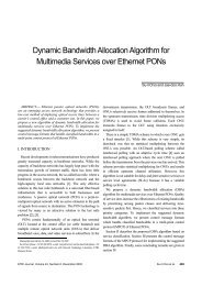
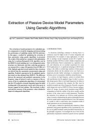
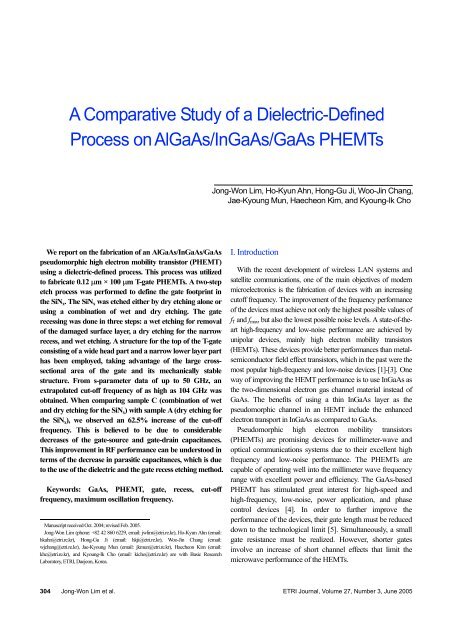
In order to reduce the gate resistance, T-shaped gates withlarge cross-sectional areas are required [6]-[8]. Theirfabrication can be either based on electron beam lithography(EBL) with multiple resist layers [9] or on optical stepperlithography combined with sidewall spacers. The shape <strong>of</strong> theT-gate, the gate footprint length L g , and the thickness <strong>of</strong> thepassivation all have a major impact on the gate capacitance C gs ,which is a key parameter for the RF performance <strong>of</strong> the device.The wider head <strong>of</strong> the T-gate decreases the gate resistance R g ,but at the same time the gate capacitance increases. Thereforethe width <strong>of</strong> the T-gate head must be chosen as a trade-<strong>of</strong>fvalue between low resistance and low capacitance [10].In this study, we demonstrate a plasma-enhanced chemicalvapor deposited SiN x -defined process. It will be shown that0.12 µm gate-length AlGaAs/InGaAs/GaAs PHEMTsfabricated using this process exhibit good DC and microwavecharacteristics. We report the results on using the differentdielectric etching technique to obtain T-gates with 0.12 µm gatelengths. Additionally, we shall prove that based on this processa mechanically stable T-gate can be formed. To achieve a lowgate resistance and a low parasitic capacitance for the bottom<strong>of</strong> the T-gate, the dielectric etch and gate recess processes havebeen modified to include two separate steps.II. Experimental DetailsThe PHEMT epitaxial structure was grown by molecularbeam epitaxy on a semi-insulating GaAs substrate and consists<strong>of</strong> the following layers: 5000 Å GaAs buffer, 30 periods <strong>of</strong> theAlGaAs/GaAs superlattice buffer, an undoped Al 0.23 Ga 0.77 Asbuffer, silicon planar doping (1 × 10 12 cm -2 ), a 20 ÅAl 0.23 Ga 0.77 As spacer, a 120 Å In 0.2 Ga 0.8 As channel, a 35 ÅAl 0.23 Ga 0.77 As spacer, silicon planar doping (4.5 × 10 12 cm -2 ),and a 250 Å Al 0.23 Ga 0.77 As Schottky contact layer. Finally, a400 Å thick undoped GaAs cap layer was grown to protect theactive layer from the oxidation causing the creation <strong>of</strong> defects[11]. The sheet carrier density <strong>of</strong> two-dimensional electron gasand the electron mobility measured at room temperature were3.4 × 10 12 cm -2 and 5750 cm 2 /V·s, respectively.The mesa was defined by conventional photolithography. TheAlGaAs/InGaAs/GaAs was etched down to the buffer layerusing a nonselective etchant, H 3 PO 4 : H 2 O 2 : H 2 O = 4 : 1 : 50.The ohmic contact patterns were defined using a lift-<strong>of</strong>ftechnique. A AuGe/Ni/Au metal system was used for thesource and drain since it is widely used as an ohmic contact toGaAs materials. Prior to the contact deposition, the GaAswafers were cleaned by dipping into an HCl : H 2 O solution;they were then rinsed in deionized water and blown dry withnitrogen. They were loaded into a thermal evaporation system,and the vacuum system was pumped to 5×10 -7 Torr beforecontact deposition. Then, the AuGe/Ni/Au ohmic contactstructure was deposited on the undoped GaAs cap layer. TheAuGe/Ni/Au layer thicknesses were 1000, 300 and 1200 Å.These ohmic contacts were heat-treated by rapid thermalannealing in a nitrogen atmosphere. The ohmic contactalloying was performed by two-step annealing, first at 340℃and then at 380℃, for 20 s each. The heat treating <strong>of</strong> the ohmicalloy at 340℃ is a step for the metallurgical stability <strong>of</strong> thegrain structure. The contacts were then examined electricallyusing transmission line model measurements. The specificcontact resistivity ρ c was 1.1 × 10 -6 Ω·cm 2 .To investigate the influence <strong>of</strong> parasitic capacitances, threesamples were processed. The steps <strong>of</strong> the fabrication <strong>of</strong> T-gatesusing a dielectric-defined layer are outlined schematically in Fig.1. A 400 Å silicon nitride layer was deposited by plasmaenhancedchemical vapor deposition at 260℃ to protect thedevice and to support the gate. The gate footprint patterning wasdone by electron beam lithography using a Leica EBPG 5000plus system operating at an acceleration voltage <strong>of</strong> 100 kV.SourceSiN xDrainFig. 1. Cross-sectional schematic view <strong>of</strong> the dielectric-definedprocess for a 0.12 µm planar-doped PHEMTs: (a) sampleA: SiN x was etched by RIE alone, (b) sample B: SiN xwas etched by using a combination <strong>of</strong> 40% wet etchingand RIE, and (c) sample C: SiN x was etched by using acombination <strong>of</strong> 60% wet etching and RIE.A 2500 Å thick layer <strong>of</strong> polymethylmethacrylate (PMMA)resist was used and developed using a mixed solution <strong>of</strong> MIBK(metylisobutylketone) and IPA (isopropylalcohol).After development <strong>of</strong> the resist, the SiN x was etched by RIEalone (sample A), using a combination <strong>of</strong> 40% wet etching andRIE (sample B), and by a combination <strong>of</strong> 60% wet etching and(a)(b)(c)<strong>ETRI</strong> <strong>Journal</strong>, Volume 27, Number 3, June 2005 Jong-Won Lim et al. 305
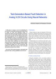
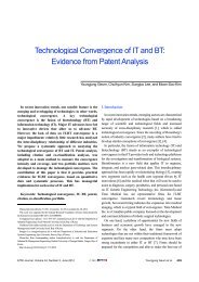
RIE (sample C). For sample A, the SiN x layer was etched usingCF 4 plasma alone to create a 0.12 µm gate footprint. Forsample B, the two-step etch process consisted <strong>of</strong> a combination<strong>of</strong> 40% wet and dry etching, and the 0.12 µm gate footprintwas also created. For sample C, the two-step etch processconsisted <strong>of</strong> a combination <strong>of</strong> 60% wet and dry etching. Thewet chemical etches SiN x isotropically, resulting in a lateralundercut, whereas the anisotropic RIE maintains the SiN xopening dimension in the resist. First, a buffered oxide etchsolution was used to widen the top <strong>of</strong> the SiN x layer defined bythe photoresist. The target was to remove about 40 to 60% <strong>of</strong>the SiN x thickness to give enough lateral undercut. Thebuffered oxide etch was diluted to slow down the etch rate inorder to have a better etch depth control. The residual SiN x wasetched <strong>of</strong>f anisotropically by RIE in CF 4 plasma. The top <strong>of</strong> theT-gate was defined by using electron beam exposure <strong>of</strong> a trilayerresist: PMMA (2500 Å)/co-polymer /PMMA (1400 Å).The top <strong>of</strong> the T-gate structure, which consists <strong>of</strong> a wide headpart and a narrow lower layer (0.3 µm), has been employedtaking advantage <strong>of</strong> its large cross-section area <strong>of</strong> the gate andmechanically stable structure. After the development <strong>of</strong> the trilayerresist, the gate recess was etched. To achieve highuniformity and reproducible gate recess processing, the GaAscap layer was selectively etched by electron cyclotronresonance (ECR) dry etching. The GaAs cap layer wasselectively etched using a BCl 3 /SF 6 gas mixture. Etchuniformity was less than 4% across a 4-inch wafer. The gaterecessing <strong>of</strong> sample A was performed using an ECR etchingprocess, and that <strong>of</strong> sample B was carried out in two stepsincluding a wet etching for the removal <strong>of</strong> the RIE damagedsurface layer and a dry etching for the narrow recess. A H 3 PO 4 :H 2 O 2 : H 2 O (4 : 1 : 180) solution was used to etch <strong>of</strong>fapproximately 20% <strong>of</strong> the GaAs cap layer. After the wetSiN x0.12 µmDrain Gate Sourceetching, the sample was then loaded into an ECR chamber forfurther etching in a BCl 3 /SF 6 gas. The gate recessing <strong>of</strong> sampleC was carried out in three steps including a wet etching for theremoval <strong>of</strong> the damaged surface layer, a dry etching for thenarrow recess, and a wet etching. The gate recess is stoppedwhen a predetermined source-drain current is reached. Afterthe gate recess, Ti/Pt/Au layers (6000 Å) were deposited andlifted-<strong>of</strong>f. Figure 2 shows an SEM image <strong>of</strong> the cross-section<strong>of</strong> a fabricated T-gate taken from an actual device.III. Results and DiscussionPHEMTs with source-to-drain spacings <strong>of</strong> 2.5 µm, sourceto-gatespacings <strong>of</strong> 0.79 µm, gate-to-drain spacings <strong>of</strong> 1.59 µm,unit gate widths <strong>of</strong> 50 µm and two gate fingers, and gatelengths <strong>of</strong> 0.12 µm were fabricated using the tri-layer resist onthe PHEMT structure described earlier. This asymmetricsource and drain structure with shorter gate-to-sourceseparation than gate-to-drain can be applied for reducing theDrain current (mA)Transconductance (mS/mm)30252015105Sample A0.12 µm × 100 µm00 1 2 3 4 5Drain voltage (V)500400300200100Sample A, V ds = 1.5 V,0.12 µm × 50 µmTop curve : V g = 0.1 V,V g step = - 0.1 V(a)00-2.0 -1.5 -1.0 -0.5 0.0 0.5 1.0Gate voltage (V)(b)282420161284Drain current (mA)Fig. 2. SEM photograph <strong>of</strong> the cross section <strong>of</strong> a recessed T-gatePHEMT.Fig. 3. (a) Drain current as a function <strong>of</strong> source-to-drain voltageand (b) the extrinsic transconductance and drain current asa function <strong>of</strong> source-to-gate voltage for the 0.12 µmPHEMT devices fabricated by RIE alone and dry gaterecess (sample A).306 Jong-Won Lim et al. <strong>ETRI</strong> <strong>Journal</strong>, Volume 27, Number 3, June 2005
source resistance. In the tri-layer process, the gate recessingwas performed, then the wet etching followed by the dryetching. The gate-length dimensions were verified byexamining the cross-sectional pr<strong>of</strong>ile <strong>of</strong> the gates in a scanningelectron microscope. The DC and RF characteristics wereevaluated by measuring the devices in an HP 4156B DCparameter analyzer and an HP 8510C network analyzer,respectively.Figure 3(a) shows the drain current as a function <strong>of</strong> sourceto-drainvoltage V ds for the 0.12 µm PHEMT device fabricatedby RIE alone with a dry gate recessing (sample A). The deviceexhibited good pinch-<strong>of</strong>f characteristics. We obtained a pinch<strong>of</strong>fvoltage <strong>of</strong> V p = – 0.61 V and a drain-source saturationcurrent I dss <strong>of</strong> 21 mA at V gs = 0 V and V ds = 5 V. The extrinsictransconductance g m and drain current I ds as a function <strong>of</strong>source-to-gate voltage V gs at a drain voltage <strong>of</strong> 1.5 V weremeasured and shown in Fig. 3(b). The maximum g m wasmeasured as 455 mS/mm at V gs = 0.12 V.Figure 4(a) shows the drain current as a function <strong>of</strong> source-to-drain voltage V ds for the 0.12 µm PHEMT device fabricatedby the combination <strong>of</strong> 40% wet etching and RIE (sample B).The device also exhibited good pinch-<strong>of</strong>f characteristics. Weobtained a pinch-<strong>of</strong>f voltage <strong>of</strong> V p = – 0.8 V and a drain-sourcesaturation current I dss <strong>of</strong> 28 mA at V gs = 0 V and V ds = 5 V. Theextrinsic transconductance g m and drain current I ds as a function<strong>of</strong> source-to-gate voltage V gs at a drain voltage <strong>of</strong> 1.5 V weremeasured and are shown in Fig. 4(b). The maximum g m wasmeasured as 435 mS/mm at V gs = 0.05 V.Figure 5(a) shows the drain current as a function <strong>of</strong> source-todrainvoltage V ds for the 0.12 µm PHEMT device fabricated bythe combination <strong>of</strong> 60% wet etching and RIE (sample C).The device also exhibited good pinch-<strong>of</strong>f characteristics. Weobtained a pinch-<strong>of</strong>f voltage <strong>of</strong> V p = – 0.66 V and a drain-sourcesaturation current I dss <strong>of</strong> 32 mA at V gs = 0 V and V ds = 5 V.The extrinsic transconductance and drain current I ds as afunction <strong>of</strong> source-to-gate voltage V gs at a drain voltage <strong>of</strong>1.5 V were measured and are shown in Fig. 5(b). Themaximum g m was measured as 610 mS/mm at V gs = 0.13 V.Drain current (mA)Transconductance (mS/mm)3530252015105500400300200100Sample B0.12 µm × 100 µmSample B, V ds = 1.5 V,0.12 µm × 50 µmTop curve : V g = 0.1 V,V g step = - 0.1 V00 1 2 3 4 5Drain voltage (V)(a)00-2.0 -1.5 -1.0 -0.5 0.0 0.5 1.0Gate voltage (V)Fig. 4. (a) Drain current as a function <strong>of</strong> source-to-drain voltageand (b) the extrinsic transconductance and drain current asa function <strong>of</strong> source-to-gate voltage for the 0.12 µmPHEMT devices fabricated by a combination <strong>of</strong> 40% wetetching and RIE (sample B).(b)282420161284Drain current (mA)Drain current (mA)Transconductance (mS/mm)403530252015105700600500400300200100Sample C0.12 µm × 100 µm00 1 2 3 4 5Drain voltage (V)Sample C, V ds = 1.5 V,0.12 µm × 50 µmTop curve : V g = 0.1 V,V g step = - 0.1 V00-2.0 -1.5 -1.0 -0.5 0.0 0.5 1.0(a)Gate voltage (V)(b)Fig. 5. (a) Drain current as a function <strong>of</strong> source-to-drain voltageand (b) the extrinsic transconductance and drain current asa function <strong>of</strong> source-to-gate voltage for the 0.12 µmPHEMT devices fabricated by a combination <strong>of</strong> 60% wetetching and RIE (sample C).403530252015105Drain current (mA)<strong>ETRI</strong> <strong>Journal</strong>, Volume 27, Number 3, June 2005 Jong-Won Lim et al. 307
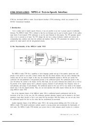
From Figs. 3 and 4, the low value <strong>of</strong> extrinsic transconductancefor sample B is due to the increase in source resistance as a result<strong>of</strong> undercutting by the wet etching prior to the dry etching. It canbe seen that, relative to sample B, sample A has a 0.19 V positiveshift in pinch-<strong>of</strong>f voltage. The dry etching time <strong>of</strong> sample A ishigher than that <strong>of</strong> sample B using a two-step recess etching.Because the GaAs cap layer was selectively etched using an SF 6and BCl 3 gas mixture, it is believed that the plasma-induceddamage <strong>of</strong> sample B is less than that <strong>of</strong> sample A. From theabove results, the positive shift is probably due to a negativecharge resulting from plasma-induced defects. When the recessdepth is increased, the effective distance between the gate andthe channel decreases. This results in an increase <strong>of</strong> thetransconductance with recess. The consideration <strong>of</strong> shortchannel effects also leads to an expected increase <strong>of</strong> thetransconductance with a recess.Gate current (mA)0.0-0.2-0.4-0.6-0.80.12 µm × 50 µm-1.0-18 -16 -14 -12 -10 -8 -6 -4 -2 0Gate-drain voltage (V)sample Asample Bsample CFig. 6. Gate to drain breakdown characteristics for the samples .Gate-to-drain breakdown voltage BV gd measurements weremade on the samples. The gate-to-drain breakdown voltagecurves are shown in Fig. 6. Sample A has a gate-to-drainbreakdown <strong>of</strong> – 11.4 V. Sample B and sample C have a gate-todrainbreakdown <strong>of</strong> – 13.3 V and – 13.9 V. The breakdownvoltage is defined at a drain-to-gate current <strong>of</strong> 1 mA/mm and ismeasured by biasing the drain at 0 V and sweeping the gatebias with the source floating. As the side-etching length isincreased, BV gd increases due to a reduction <strong>of</strong> the maximumelectric field strength at the drain side [12].The RF properties <strong>of</strong> the fabricated PHEMTs were measuredby on-wafer probing from 0.5 to 50 GHz using a Cascademicrowave probe station and an HP8510C network analyzer.Typical current gain h 21 and maximum stable and availablegains (MSG/MAG) as a function <strong>of</strong> frequency for sample Aare shown in Fig. 7(a). The drain and gate voltages applied inthe RF measurements were 1.5 and 0.1 V, respectively. Fromh21& MSG/MAG (dB)h21& MSG/MAG (dB)h21 & MSG/MAG (dB)45403530252015105045403530252015105050454035302520151050h 21MSG/MAG10 9 10 10 10 11h 21MSG/MAGFrequency (Hz)Frequency (GHz)Frequency (Hz)(c)Fig. 7. Measured current gain and maximum available gain as afunction <strong>of</strong> frequency for (a) sample A, (b) sample B and(c) sample C.(a)(b)f T = 64 GHz10 9 10 10 10 11h 21MSG/MAGf max = 208 GHzf T = 89 GHzf T = 104 GHz10 9 10 10 10 11f max = 240 GHzf max = 190 GHzthe measured S-parameters, the small-signal equivalent circuitwas extracted using a direct extraction technique, and thecorresponding f T and f max were estimated. Both f T and f max werecalculated using the h 21 and MSG/MAG values by an308 Jong-Won Lim et al. <strong>ETRI</strong> <strong>Journal</strong>, Volume 27, Number 3, June 2005
Table 1. Small signal equivalent circuit parameters at V ds = 1.5 V and V gs = 0.1 V. The parameters were obtained by equivalent circuitanalysis.Device L g (µm) W g (µm) No. <strong>of</strong> fingers g m (mS) C gs (fF) C gd (fF) C ds (fF) R g (Ω) R s (Ω) R i (Ω) R d (Ω) τ (ps)Sample A 0.1 50 2 53 127.5 9.3 44.1 1.3 1.4 3.7 3.5 0.99Sample B 0.1 50 2 54 95.7 7.6 43.7 0.8 1.9 5.9 7.4 0.73Sample C 0.1 50 2 69 81.2 7.0 41.3 0.7 5.0 8.0 10.8 0.65L g : gate length, W g : gate width, g m : transconductance, C gs : gate-source capacitance, C gd : gate-drain capacitance, C ds : drain-source capacitance, τ : transit time, R g : gateresistance, R s : source resistanceextrapolation <strong>of</strong> a –20 dB/decade slope. The current gain cut<strong>of</strong>ffrequency f T was 64 GHz and the maximum oscillationfrequency f max was 208 GHz.Current gain h 21 and MSG/MAG as a function <strong>of</strong> frequencyfor sample B are shown in Fig. 7(b). The extrapolated cut-<strong>of</strong>ffrequency f T and the maximum oscillation frequency f max were89 GHz and 240 GHz, respectively. And current gain h 21 andMSG/MAG as a function <strong>of</strong> frequency for sample C are shownin Fig. 7(c). The extrapolated cut-<strong>of</strong>f frequency f T and themaximum oscillation frequency f max were 104 GHz and 190GHz, respectively.This result was comparable to the previously reported valuefor a conventional PHEMT process [13], [14]. In order toinvestigate the increase <strong>of</strong> cut-<strong>of</strong>f frequency, the parameters inthe small signal equivalent circuit model were extracted at themaximum transconductance bias point and are shown inTable 1. The most prevalent method for obtaining equivalentcircuit parameters is fitting by circuit simulation. In Table 1, wesee that sample A has the largest R g and sample C has thesmallest. This can be understood by the fact that the wetprocess in the SiN x etching ensures better connectivity <strong>of</strong> thefootprint <strong>of</strong> the T-gate to the top. On the other hand, sample Ahas the smallest R s and R d , whereas sample C has the largestdue to the lateral etching in the wet process <strong>of</strong> the recessetching. The value <strong>of</strong> C ds is similar for samples A, B and Csince this parameter represents the coupling between sourceand drain that takes place mainly through the carriers in thebuffer, which practically are not affected by the inclusion <strong>of</strong> theT-gate. However, important differences appear in the values <strong>of</strong>C gs and C gd . Sample C shows a more significant decrease inthese values than samples A and B. This effect becomes clearlyapparent when the small signal circuit parameters arecalculated, revealing that gate-drain and gate-sourcecapacitances are increased due to the capacitive couplingbetween the head <strong>of</strong> the gate and the semiconductor. The head<strong>of</strong> the T-gate provokes a capacitive coupling between gate andsemiconductor. This affects considerably the distribution <strong>of</strong> theelectric field inside the device. The main difference appearingwhen the T-gate geometry is considered is a decrease in thepotential in the semiconductor regions under the flanks <strong>of</strong> theT-gate head due to the influence <strong>of</strong> the negative gate potentialapplied to the gate, which is not completely shielded by thepresence <strong>of</strong> the dielectric between the gate head and thesemiconductor. This effect takes place mainly in the regionsbelow the part <strong>of</strong> the recess that is not in contact with the gateelectrode. The capacitive coupling between the head <strong>of</strong> the T-gate and the semiconductor must have some influence on thecapacitive elements <strong>of</strong> the small signal equivalent circuitassociated with the gate. In the case <strong>of</strong> sample A, the values <strong>of</strong>C gs and C gd are 127.5 and 9.3 fF, respectively. In the case <strong>of</strong>sample B, the values <strong>of</strong> C gs and C gd are 95.7 and 7.6 fF,respectively. And, in the case <strong>of</strong> sample C, the values <strong>of</strong> C gs andC gd are 81.2 and 7.0 fF, respectively. These results show thatparasitic capacitances are essentially localized between the top<strong>of</strong> the T-gate and the cap layer through the dielectric coatinglayer. By avoiding the presence <strong>of</strong> passivation under the T-gate,parasitic capacitances can be reduced and high-frequencyparameters can then be improved. A way to reduce the averagedielectric constant in the space between the semiconductorsurface and the contacts is to decrease the thickness <strong>of</strong> thedielectric layer, such that this space is partially filled with air[15]. From the above results, the improvement in RFperformance can be understood in terms <strong>of</strong> the decrease inparasitic capacitances due to dielectric and gate recess etchingmethod. This method is promising in solving the problem <strong>of</strong>decreasing the parasitic capacitance for short gate lengths aswell as obtaining a mechanically stable T-gate structure. Adielectric-defined process has been successfully used t<strong>of</strong>abricate 0.12 µm gate length planar-doped AlGaAs/InGaAs/GaAs PHEMTs. Good DC and microwave performances areachieved by these devices, demonstrating the suitability <strong>of</strong> theprocess for fabricating short gate length devices. And thisprocess can be implemented on sub-100 nm devices since thee-beam lithography is separated. Compared to the conventionalprocess, this process protects the active channel area andprevents the device characteristics from drifting over a longtime period. Moreover, it is shown that the process <strong>of</strong>fers thepossibility <strong>of</strong> decreasing the resistance and capacitance <strong>of</strong> short<strong>ETRI</strong> <strong>Journal</strong>, Volume 27, Number 3, June 2005 Jong-Won Lim et al. 309
gate fingers by forming mechanically stable T-gates.IV. ConclusionThe fabrication <strong>of</strong> a 0.12 µm T-gate by means <strong>of</strong> a dielectricdefinedprocess has been described. The gate footprint patternis transferred into the silicon nitride layer by a two-step etchingprocess which consists <strong>of</strong> wet etching in a diluted bufferedoxide etch followed by RIE in CF 4 plasma. The gate recessingwas carried out in three steps including wet etching for removal<strong>of</strong> the damaged surface layer, dry etching for the narrow recess,and wet etching. We observed the increase <strong>of</strong> cut-<strong>of</strong>f frequencyf T from 64 to 104 GHz. The improvement in RF performancecan be understood in terms <strong>of</strong> the decrease in parasiticcapacitances due to the use <strong>of</strong> SiN x and the gate recess etchingmethod. This method is a promising process in terms <strong>of</strong>decreasing the parasitic capacitance for short gate lengths aswell as obtaining a mechanically stable T-gate structure.References[1] F. Schwierz and J.J. Liou, “Semiconductor Devices for RFApplications: Evolution and Current Status,” MicroelectronicsReliability, vol. 41, 2001, pp. 145-168.[2] C.Y. Chang and F. Kai, GaAs High-Speed Devices, WileyInterscience, New York, 1994.[3] D. Pavlidis, “HBT vs. PHEMT vs. MESFET: What’s Best andWhy,” GaAs MANTECH Conf. Digest <strong>of</strong> Papers, 1999, pp. 157-160.[4] Stanimir D. Kamenopolsky, “Application <strong>of</strong> GaAs Discrete p-HEMTs in Low Cost Phase Shifters and QPSK Modulators,”<strong>ETRI</strong> J., vol. 26, no. 4, 2004, pp. 307-314.[5] Y. Yamashita, A. Endoh, K. Shinohara, K. Hikosaka, T. Matsui, S.Hiyamizu, and T. Mimura, “Pseudomorphic In 0.52 Al 0.48 As/ In0.7Ga 0.3 As HEMTs with an Ultrahigh f T <strong>of</strong> 562 GHz,” IEEEElectron Device Lett., vol. 23, 2002, pp. 573-575.[6] J.H. Lee, H.S. Yoon, and C.S. Park, “Ultra Low NoiseCharacteristics <strong>of</strong> AlGaAs/InGaAs/GaAs PseudomorphicHEMTs with Wide Head T-shaped Gate,” IEEE Electron DeviceLett., vol. 16, no.6, 1995, pp. 271-273.[7] J.H. Lee, H.S. Yoon, B.S. Park, C.S. Park, S.S. Choi, and K.E.Pyun, “Pseudomorphic AlGaAs/InGaAs/GaAs High ElectronMobility Transistors with Super Low Noise Performances <strong>of</strong> 0.41dB at 18 GHz,” <strong>ETRI</strong> J., vol. 18, no. 3, 1996, pp. 171-179.[8] J.H. Lee, H.S. Yoon, J.Y. Shim, and H. Kim, “DeviceCharacteristics <strong>of</strong> AlGaAs/InGaAs HEMTs Fabricated byInductively Coupled Plasma Etching,” Thin Solid Films, vol. 435,2003, pp. 139-144.[9] F. Ren, S.J. Pearton, D.M. Tennant, D.J. Resnick, C.R. Abernathy,R.F. Kopf, C.S. Wu, M. Hu, C.K. Pao, B. M. Paine, D.C. Wang,and C.P. Wen, “Dry Etching Bilayer and Trilevel Resist Systemsfor Submicron Gate Length GaAs Based High Electron MobilityTransistors for Power and Digital Applications,” J. <strong>of</strong> VacuumScience and Technology B, vol. 10, no. 6, 1992, pp. 2949-2953.[10] J. Mateos, T. González, D. Pardo, V. Hoel, and A. Cappy, “Effect<strong>of</strong> the T-gate on the Performance <strong>of</strong> Recessed HEMTs. A MonteCarlo Analysis,” Semiconductor Science and Technology, vol. 14,1999, pp. 864-870.[11] J.L. Lee, D. Kim, S.J. Maeng, H.H. Park, J.Y. Kang, and Y.T. Lee,“Improvement <strong>of</strong> Breakdown Characteristics <strong>of</strong> a GaAs PowerField-Effect Transistor Using (NH 4 ) 2 S x Treatment,” J. <strong>of</strong> AppliedPhysics, vol. 73, Issue 7, 1993, pp. 3539-3542.[12] T. Ohshima, M. Yoshida, R. Shigemasa, M. Tsunotani, and T.Kimura, “Gate Orientation Dependence <strong>of</strong> InGaAs/AlGaAs HighElectron Mobility Transistors Formed by Wet Recess Etching,”Japanese J. <strong>of</strong> Applied Physics, vol. 39, no. 9A, 2000, pp. 5052-5056.[13] H.S. Kim, B.O. Lim, S.C. Kim, S.D. Lee, D.H. Shin, and J.K.Rhee, “<strong>Study</strong> <strong>of</strong> the Fabrication <strong>of</strong> PHEMTs for a 0.1 µm Scale Γ-gate Using Electron Beam Lithography: Structure, Fabrication,and Characteristics,” Microelectronic Eng., vol. 63, 2002, pp. 417-431.[14] Y.C. Chou, P. Nam, G.P. Li, R. Lai, H.K. Lim, R. Grundbacher, E.Ahlers, Y. Ra, Q. Xu, M. Biedenbender, and A. Oki, “InnovativeNitride Passivation for Pseudomorphic GaAs HEMTs and Impacton Device Performance,” IEEE 40th Annual Int’l ReliabilityPhysics Symp., 2002, pp. 235-240.[15] O. Schuler, H. Fourré, R. Fauquembergue, and A. Cappy,“Influence <strong>of</strong> Parasitic Capacitances on the Performance <strong>of</strong>Passivated InAlAs/InGaAs HEMTs in the Millimeter WaveRange,” 8th Int’l Conf. on Indium Phosphide and RelatedMaterials, 1996, pp. 646.Jong-Won Lim received the BS, MS, and PhDdegrees in physics from Chung-Ang Universityin Seoul, Korea, in 1988, 1990 and 1998. In1998, he joined the Electronics andTelecommunications Research Institute (<strong>ETRI</strong>)<strong>of</strong> Korea as a Senior Member <strong>of</strong> Research Staff<strong>of</strong> Compound Semiconductor Department,where he has been engaged in research on compound semiconductorMMIC developments for wireless telecommunications. His researchinterests are in the development <strong>of</strong> 60 GHz wide-band wireless LANtechnology.310 Jong-Won Lim et al. <strong>ETRI</strong> <strong>Journal</strong>, Volume 27, Number 3, June 2005
Ho-Kyun Ahn received BS and MS degrees inmaterial science and engineering from KoreaUniversity, Korea, in 1999 and 2001. He joined<strong>ETRI</strong> in 2001. Since 2001, he has beeninvolved in developing an e-beam lithographyprocess and fabrication process <strong>of</strong> GaAs relateddevices. He is now a Member <strong>of</strong> EngineeringStaff in the High Speed SOC Research Department in <strong>ETRI</strong>. Hiscurrent research interests include the fabrication and characterization <strong>of</strong>high frequency GaAs-based HEMTs and the development <strong>of</strong> a fineline lithography process for nanometer devices.Hong-Gu Ji received the BS and MS degreesin radio and science engineering fromKwangwoon University in Seoul, Korea, in1998 and 2000. From 2000, he has been with<strong>ETRI</strong> as a Member <strong>of</strong> Research Staff, where heis engaged in research on MMIC designs.Woo-Jin Chang received the BS and MSdegrees in information engineering from KoreaUniversity, Korea, in 1996 and 1998. From1998 to 1999, he was with LG Precision, wherehe worked on power amplifier MMIC designsfor CDMA systems. In the middle <strong>of</strong> 1999 hejoined <strong>ETRI</strong>, where he has been engaged inresearch on device modeling and micro-/millimeter-wave MMICdesign for active antenna systems and wide-band wireless LANsystems. Since March 2002, he has been a Senior Member <strong>of</strong> ResearchStaff <strong>of</strong> High Speed SoC Research Department <strong>of</strong> <strong>ETRI</strong>. His researchinterests include device modeling and micro-/millimeter-waveamplifier design.Haecheon Kim received the BS degree inmetallurgical engineering from Seoul NationalUniversity in 1982 and the MS degree inmaterials science and engineering from KAISTin Seoul, Korea, in 1984. He earned the PhDdegree in materials science and engineeringfrom Illinois Institute <strong>of</strong> Technology (IIT) inChicago, USA, in 1992. From 1984 to 1988, he was with LGElectronics, as a Senior Research Member <strong>of</strong> Central Research Center,where he was engaged in R&D on magnetic materials for 8 mm videotape and thin film transistors for LCD panels. In 1993, he joined <strong>ETRI</strong>as a Senior Member <strong>of</strong> Research Staff <strong>of</strong> Compound SemiconductorDepartment. He is currently leading the Microwave Devices Team.His research interests are on the development <strong>of</strong> advancedsemiconductor devices and MMICs for their system application.Kyoung-Ik Cho received the BS degree inmaterials science from Ulsan Institute <strong>of</strong>Technology in 1979, and the MS and PhDdegrees in material science and engineeringfrom KAIST in 1981 and 1991. He joined<strong>ETRI</strong> in 1981. At present, he is a PrincipalMember <strong>of</strong> Research Staff at <strong>ETRI</strong> BasicResearch Laboratory. His research interests include millimeter-waveand optoelectronic devices for 60 GHz radio-on-fiber communicationsystems, reconfigurable SoC for next generation integrated handheldterminals, and advanced flat panel display devices such as fieldemission displays and digital paper.Jae-Kyoung Mun was born in Gosung, Koreain 1966. He received the BS degree in materialscience and engineering from Ajou Universityin 1990 and the MS degree in materialsengineering from Korea Advanced Institute <strong>of</strong>Science and Technology (KAIST) in 1992. Hejoined <strong>ETRI</strong> in 1992, where he has beenengaged in R&D on advanced compound semiconductor MMICdevelopments for wireless communications. His research interestsinclude backside processing, such as lapping/polishing and goldbumping, and reliability issues <strong>of</strong> GaAs MESFETs and pHEMTs forcore components <strong>of</strong> high power amplifiers and RF switches. Recently,he has been involved in LTCC module design.<strong>ETRI</strong> <strong>Journal</strong>, Volume 27, Number 3, June 2005 Jong-Won Lim et al. 311