IVECO Daily 29 L11 - 35 S13 - TOP DRIVE SYSTEM
IVECO Daily 29 L11 - 35 S13 - TOP DRIVE SYSTEM
IVECO Daily 29 L11 - 35 S13 - TOP DRIVE SYSTEM

Create successful ePaper yourself
Turn your PDF publications into a flip-book with our unique Google optimized e-Paper software.
4.0441-IM-ENG-VB<br />
Distributed by :<br />
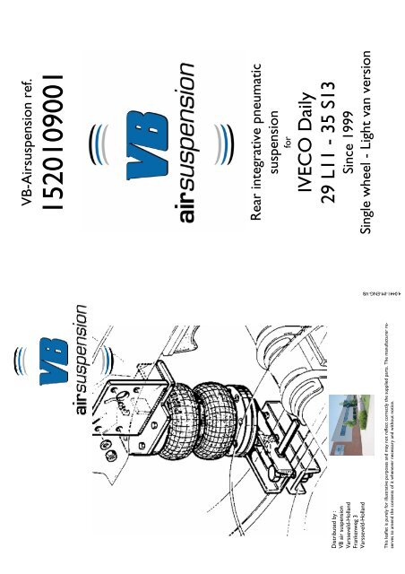
VB air suspension<br />
Varsseveld-Holland<br />
Frankenweg 3<br />
Varsseveld-Holland<br />
This leaflet is purely for illustrative purposes and may not reflect correctly the supplied parts. The manufacturer reserves<br />
to amend the contents of it whenever necessary and without notice.<br />
VB-Airsuspension ref.<br />
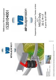
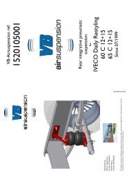
1520109001<br />
Rear integrative pneumatic<br />
suspension<br />
for<br />
<strong>IVECO</strong> <strong>Daily</strong><br />
<strong>29</strong> <strong>L11</strong> - <strong>35</strong> <strong>S13</strong><br />
Since 1999<br />
Single wheel - Light van version
INSTALLATION INSTRUCTIONS<br />
PACKAGE CONTENT<br />
Ø15x28 (4X)<br />
M10x<strong>35</strong> (8X)<br />
M8x20 (2X)<br />
M6x16 (1X)<br />
M8x45 (2X)<br />
M14 (4X)<br />
Ø6 (1X)<br />
Fast pipe fitting for<br />
differential gearbox<br />
breather (1x)<br />
Plate (2x)<br />
M6 (1X)<br />
(1X)<br />
M10 (8X) M8 (3X)<br />
Ø8 (1X)<br />
M14x70 (2x)<br />
SMALL HARDWARE KIT<br />
Ø10 (8X)<br />
Right suspension (1x)<br />
Left suspension (1x)<br />
Ringnut<br />
Support<br />
plate<br />
Valve body<br />
<strong>TOP</strong> <strong>DRIVE</strong><br />
CONTROL<br />
Pressures stick (1X).<br />
cap<br />
RILSAN KIT PIPE composed by:<br />
• Red pipe (6 m);<br />
• Black pipe (6 m).<br />
MANOMETERS box composed<br />
by:<br />
• Manometers with plastic<br />
ringnut (2x);<br />
• Inflating valves (2x);<br />
• Caps (for manometers) (2x).<br />
• Gauge support (1x)<br />
PRESSURE CONTROL KIT<br />
Composed by:<br />
• Valve body with pipe fittings<br />
(2x);<br />
• Caps (6x);<br />
• Support plate (2x);<br />
• Ringnut (2x).<br />
CLIPS KIT<br />
Composed by:<br />
• Plastic clips (20x).<br />
Pneumatic system<br />
instructions (1x)<br />
nuts FRONT<br />
SIDE OF<br />
1<br />
Wear indicator plug<br />
2<br />
3 4<br />
<strong>DRIVE</strong><br />
Fit rilsan pipe in the pipe fittings:<br />
• Red for right side;<br />
• Black for left side.<br />
Unscrew support nuts (external<br />
side of chassis) and disconnect<br />
wear indicator plug (left and right<br />
side).<br />
Place suspension between axle and chassis. Put the upper linking<br />
system on the chassis, as showed, and use the upper hole to pass<br />
wear indicator through chassis and suspension.<br />
A<br />
5<br />
B 6 7<br />
Fit bottom side of suspension using nuts and washers issued.<br />
B point of support for spacer plate.<br />
Adjust, according to leaf spring thickness, length “A” whit adjuster<br />
screw and lock it with lock nut.<br />
REAR BRAKE REGULATOR MODIFICATIONS INSTRUCTIONS<br />
Unscrew lower screw of rod and replace<br />
it using 45x20 plate (with Ø 6<br />
mm holes), using M6x16 screw and M6<br />
nut and Ø6 washer.<br />
Brake regulator rod<br />
Use M6x16<br />
screw and nut<br />
and washer.<br />
Bend support pipe fitting plate,<br />
welded at the axle, in direction<br />
of the ground, becoming it<br />
plane, as showed.<br />
Use M8 screw and respective<br />
nut and washer.<br />
T pipe fittings brake.<br />
Move T brake pipe fittings using 60x20<br />
plate and M8 screw, nut and washer.<br />
NOTE: if the vehicle has two T<br />
brake pipe fittings repeat this operation<br />
using other 60x20 plate.<br />
DIFFERENTIAL GEARBOX BREATHER<br />
LEFT SIDE<br />
1<br />
2<br />
Install pipe<br />
fitting issued.<br />
3<br />
Differential side<br />
Remove pipe<br />
fittings<br />
Oil differential<br />
breather<br />
Modify differential oil breather placed in the left side of axle. Unscrew existing<br />
breather (pict. 1) and place L pipe fittings issued rotating the exit in directions of the<br />
centre of vehicle (pict. 3). Fit, approx 40 cm of pipe, in the pipe fitting and lock the<br />
other side in the upper side of differential gearbox.<br />
Put the work pressure stick in a place visible for the driver, in the<br />
cabin.<br />
NOTE: for the execution of pneumatic system, follow specific<br />
instructions not included in this manual. See the “pneumatic<br />
system: installation instructions” form (see picture right).<br />
WARNING : For the execution of the pneumatic system, please strictly refer the specific given instructions. In fact , the system may vary according<br />
to the chosen version (manual, self levelling or electrical); so than the instructions for the pneumatic system are stated in the<br />
apposite handbook enclosed at the purchased kit.<br />
IMPORTANT: do NOT use liquid Teflon®, hemp, paints etc. .In case of problem and/or information, contact our technical office. In case you fail to<br />
comply at this indications, societies EUROSERVICE s.r.l. and ESI Italia s.r.l. aren’t responsible for eventually damages derivates. For further information<br />
contact us.