wire rope safety - Bridon
wire rope safety - Bridon
wire rope safety - Bridon

You also want an ePaper? Increase the reach of your titles
YUMPU automatically turns print PDFs into web optimized ePapers that Google loves.
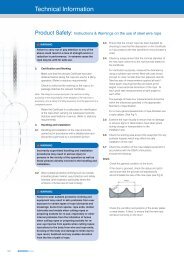
General Technical Information<br />
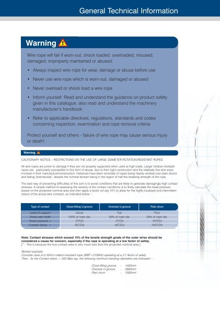
Warning<br />
Wire <strong>rope</strong> will fail if worn-out, shock loaded, overloaded, misused,<br />
damaged, imp<strong>rope</strong>rly maintained or abused.<br />
• Always inspect <strong>wire</strong> <strong>rope</strong> for wear, damage or abuse before use<br />
• Never use <strong>wire</strong> <strong>rope</strong> which is worn-out, damaged or abused<br />
• Never overload or shock load a <strong>wire</strong> <strong>rope</strong><br />
• Inform yourself: Read and understand the guidance on product <strong>safety</strong><br />
given in this catalogue; also read and understand the machinery<br />
manufacturer’s handbook<br />
• Refer to applicable directives, regulations, standards and codes<br />
concerning inspection, examination and <strong>rope</strong> removal criteria<br />
Protect yourself and others - failure of <strong>wire</strong> <strong>rope</strong> may cause serious injury<br />
or death!<br />
Warning<br />
CAUTIONARY NOTICE – RESTRICTIONS ON THE USE OF LARGE DIAMETER ROTATION-RESISTANT ROPES.<br />
All <strong>wire</strong> <strong>rope</strong>s are prone to damage if they are not p<strong>rope</strong>rly supported when used at high loads. Larger rotation-resistant<br />
<strong>rope</strong>s are particularly susceptible to this form of abuse, due to their rigid construction and the relatively fine <strong>wire</strong> sizes<br />
involved in their manufacture/construction. Instances have been recorded of <strong>rope</strong>s being heavily worked over plain drums<br />
and failing "prematurely", despite the nominal tension being in the region of half the breaking strength of the <strong>rope</strong>.<br />
The best way of preventing difficulties of this sort is to avoid conditions that are likely to generate damagingly high contact<br />
stresses. A simple method of assessing the severity of the contact conditions is to firstly calculate the tread pressure<br />
based on the projected nominal area and then apply a factor (of say 10*) to allow for the highly localised and intermittent<br />
nature of the actual <strong>wire</strong> contacts, as indicated below :-<br />
Type of contact Close-fitting U-groove Oversize U-groove Plain drum<br />
Level of support Good Fair Poor<br />
Tread path width 100% of <strong>rope</strong> dia. 50% of <strong>rope</strong> dia. 20% of <strong>rope</strong> dia.<br />
Tread pressure = 2T/Dd 4T/Dd 10T/Dd<br />
Contact stress = 20T/Dd 40T/Dd 100T/Dd<br />
Note: Contact stresses which exceed 10% of the tensile strength grade of the outer <strong>wire</strong>s should be<br />
considered a cause for concern, especially if the <strong>rope</strong> is operating at a low factor of <strong>safety</strong>.<br />
[* - This is because the true contact area is very much less than the projected nominal area.]<br />
Worked example:<br />
Consider case of a 50mm rotation-resistant <strong>rope</strong> (MBF=2100kN) operating at a 3:1 factor of <strong>safety</strong>.<br />
Then, for the Contact stress < 200 Mpa say, the following minimum bending diameters are indicated :-<br />
Close-fitting groove - 1400mm<br />
Oversize U-groove - 2800mm<br />
Plain drum - 7000mm