
Create successful ePaper yourself
Turn your PDF publications into a flip-book with our unique Google optimized e-Paper software.
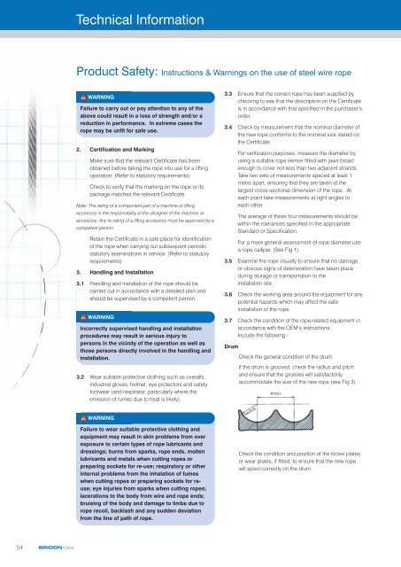
Technical Information<strong>Product</strong> <strong>Safety</strong>: Instructions & Warnings on the use of steel wire ropeWARNINGFailure to carry out or pay attention to any of theabove could result in a loss of strength and/or areduction in performance. In extreme cases therope may be unfit for safe use.2. Certification and MarkingMake sure that the relevant Certificate has beenobtained before taking the rope into use for a liftingoperation. (Refer to statutory requirements)Check to verify that the marking on the rope or itspackage matches the relevant Certificate.Note: The rating of a component part of a machine or liftingaccessory is the responsibility of the designer of the machine oraccessory. Any re-rating of a lifting accessory must be approved by acompetent person.Retain the Certificate in a safe place for identificationof the rope when carrying out subsequent periodicstatutory examinations in service. (Refer to statutoryrequirements)3. Handling and Installation3.1 Handling and installation of the rope should becarried out in accordance with a detailed plan andshould be supervised by a competent person.WARNINGIncorrectly supervised handling and installationprocedures may result in serious injury topersons in the vicinity of the operation as well asthose persons directly involved in the handling andinstallation.3.2 Wear suitable protective clothing such as overalls,industrial gloves, helmet, eye protectors and safetyfootwear (and respirator, particularly where theemission of fumes due to heat is likely).WARNINGFailure to wear suitable protective clothing andequipment may result in skin problems from overexposure to certain types of rope lubricants anddressings; burns from sparks, rope ends, moltenlubricants and metals when cutting ropes orpreparing sockets for re-use; respiratory or otherinternal problems from the inhalation of fumeswhen cutting ropes or preparing sockets for reuse;eye injuries from sparks when cutting ropes;lacerations to the body from wire and rope ends;bruising of the body and damage to limbs due torope recoil, backlash and any sudden deviationfrom the line of path of rope.3.3 Ensure that the correct rope has been supplied bychecking to see that the description on the Certificateis in accordance with that specified in the purchaser’sorder.3.4 Check by measurement that the nominal diameter ofthe new rope conforms to the nominal size stated onthe Certificate.For verification purposes, measure the diameter byusing a suitable rope vernier fitted with jaws broadenough to cover not less than two adjacent strands.Take two sets of measurements spaced at least 1metre apart, ensuring that they are taken at thelargest cross-sectional dimension of the rope. Ateach point take measurements at right angles toeach other.The average of these four measurements should bewithin the tolerances specified in the appropriateStandard or Specification.For a more general assessment of rope diameter usea rope calliper. (See Fig 1)3.5 Examine the rope visually to ensure that no damageor obvious signs of deterioration have taken placeduring storage or transportation to theinstallation site.3.6 Check the working area around the equipment for anypotential hazards which may affect the safeinstallation of the rope.3.7 Check the condition of the rope-related equipment inaccordance with the OEM’s instructions.Include the following -DrumCheck the general condition of the drum.If the drum is grooved, check the radius and pitchand ensure that the grooves will satisfactorilyaccommodate the size of the new rope (see Fig 3)RADIUSPITCHCheck the condition and position of the kicker platesor wear plates, if fitted, to ensure that the new ropewill spool correctly on the drum.54BRIDON Crane
Technical Information<strong>Product</strong> <strong>Safety</strong>: Instructions & Warnings on the use of steel wire ropeSheavesEnsure that the grooving is of the correct shape andsize for the new ropeCheck that all sheaves are free to rotate and ingood condition.Rope guardsCheck that any rope guards are correctly fitted andare in good condition.Check the condition of any wear plates or rollerswhich are protecting structural members.CoilsPlace the coil on the ground and roll it out straightensuring that it does not become contaminated withdust/grit, moisture or any other harmful material.(See Fig. 5)WARNINGFailure to carry out any of the above could result inunsatisfactory and unsafe rope performance.Note: Grooves must have clearance for the rope and provideadequate circumferential support to allow for free movement of thestrands and facilitate bending. When grooves become worn and therope is pinched at the sides, strand and wire movement is restrictedand the ability of the rope to bend is reduced. (See Fig. 4)Fig 4If the coil is too large to physically handle it may beplaced on a ‘swift’ turntable and the outside end ofthe rope pulled out allowing the coil to rotate.(See Fig. 5)WARNINGFig 5Never pull a rope away from a stationary coil asthis will induce turn into the rope and kinks willform. These will adversely affect ropeperformance. (See Fig. 6)Sheave groovetoo narrowSheave groovetoo wideSheave groove correctlysupporting the rope for33% of its circumferenceFig 6WRONGNote the kinksWhen a new rope is fitted a variation in sizecompared with the old worn rope will be apparent.The new rope may not fit correctly into the previouslyworn groove profile and unnecessary wear and ropedistortion is likely to occur. This may be remedied bymachining out the grooves before the new rope isinstalled. Before carrying out such action the sheavesor drum should be examined to ensure that there willbe sufficient strength remaining in the underlyingmaterial to safely support the rope.The competent person should be familiar with therequirements of the appropriateapplication/machinery standard.Note: General guidance to users is given in ISO 4309 Code ofpractice for the selection, care and maintenance of steel wire rope.Transfer the wire rope carefully from the storage areato the installation site.BRIDON Crane55
Technical Information<strong>Product</strong> <strong>Safety</strong>: Instructions & Warnings on the use of steel wire ropeReelsPass a shaft through the reel and place the reel in asuitable stand which allows it to rotate and be brakedto avoid overrun during installation. Where multi-layercoiling is involved it may be necessary for the reel tobe placed in equipment which has the capability ofproviding a back tension in the rope as it is beingtransferred from reel to drum. This is to ensure thatthe underlying (and subsequent) laps are woundtightly on the drum. (See Fig. 7)Ensure that the reel stand is mounted so as not tocreate a reverse bend during reeving (i.e. for a winchdrum with an overlap rope, take the rope off the top ofthe reel). (See Fig. 7)3.9 Ensure that any equipment or machinery to be ropedis correctly and safely positioned and isolated fromnormal usage before installation commences. Referto the OEM’s instruction manual and the relevant‘Code of Practice’.3.10 When releasing the outboard end of the rope from areel or coil, ensure that this is done in a controlledmanner. On release of the bindings and servingsused for packaging, the rope will want to straightenitself from its previously bent position. Unlesscontrolled, this could be a violent action. Stand clear.Fig 7Position the reel and stand such that the fleet angleduring installation is limited to 1.5 degrees.(See Fig. 8)WARNINGFailure to control could result in injury.Ensure that the as-manufacturedcondition of the rope is maintainedduring installation.If a loop forms in the rope ensure that it does nottighten to form a kink.WARNINGANGLE OFFLEETCENTRE LINEOF REELCENTRE LINEOF SHEAVEFig 8A kink can severely affect the strength of a sixstrand rope and can result in distortion of arotation- resistant or low rotation rope leading toits immediate discard.Fig 9If installing the new rope with the aidof an old one, one method is to fit awire rope sock (or stocking) to eachof the rope ends. Always ensure thatthe open end of the sock (orstocking) is securely attached to therope by a serving or alternatively by aclip(See Fig. 9). Connect the two endsvia a length of fibre rope of adequatestrength in order to avoid turn beingtransmitted from the old rope into thenew rope. Alternatively a length offibre or steel rope of adequatestrength may be reeved into thesystem for use as a pilot/messengerline. Do not use a swivel during theinstallation of the rope.56BRIDON Crane
Technical Information<strong>Product</strong> <strong>Safety</strong>: Instructions & Warnings on the use of steel wire rope3.11 Monitor the rope carefully as it is being pulled into thesystem and make sure that it is not obstructed by anypart of the structure or mechanism which may causethe rope to come free.A minimum of two servings either side of the cut (seefig 10) is normally sufficient for ropes up to 100mmdiameter and for larger ropes a minimum of fourservings either side of the cut should be applied. It isessential that the correct size serving wire or strand(see fig 10a) is used and that adequate tension isapplied during the serving process to ensure theintegrity of the rope is maintained. It is particularlyimportant to maintain the integrity of non-preformedropes, multistrand rotational resistant ropes andparallel closed ropes as failure to do so could affectthe ropes breaking strength and performance inservice. During the serving procedure, servingmallets and hand operated serving machines can beused to generate tight servings.<strong>Bridon</strong> ‘On-site serving instructions’Rope DiameterDiameter of ServingWire or StrandSingle Wire1x7 WireStrand100mmFig 10an/a3.60mmThis entire operation should be carried out carefully andslowly under the supervision of a competent person.3.12 Take particular care and note the manufacturer’sinstructions when the rope is required to be cut.Apply secure servings on both sides of the cut mark.(See Fig. 10 for typical method of applying a servingto a multi-layer rope.)Ensure that the length of serving is at least equal to tworope diameters. (Note: Special servings are required forspiral ropes, i.e. spiral strand and locked coil.)Arrange and position the rope in such a manner thatat the completion of the cutting operation the ropeends will remain in position, thus avoiding anybacklash or any other undesirable movement.Cut the rope with a high speed abrasive disc cutter.Other suitable mechanical or hydraulic shearingequipment may be used although not recommendedwhen a rope end is required to be welded or brazed.For serving instructions for FL and HL ropes refer to<strong>Bridon</strong>.BRIDON Crane57
Technical Information<strong>Product</strong> <strong>Safety</strong>: Instructions & Warnings on the use of steel wire ropeWARNINGWhen using a disc cutter be aware of the dangerfrom sparks, disc fragmentation and fumes.(Refer 3.2.)Ensure adequate ventilation to avoid any build-up offumes from the rope and its constituent partsincluding any fibre core (natural or synthetic) any ropelubricant(s) and any synthetic filling and/or coveringmaterial.When terminating a rope end with a wedge socket,ensure that the rope tail cannot withdraw through thesocket by securing a clamp to the tail or by followingthe manufacturer’s instructions.(See Fig. 11 for two recommended methods ofsecuring the rope tail of a wedge socket termination).WARNINGSome special ropes contain synthetic materialwhich, when heated to a temperature higher thannormal production processing temperatures, willdecompose and may give off toxic fumes.WARNINGRope produced from carbon steel wires in the formshipped is not considered a health hazard. Duringsubsequent processing (e.g. cutting, welding,grinding, cleaning) dust and fumes may beproduced which contain elements which mayaffect exposed workers.The products used in the manufacture of steel wireropes for lubrication and protection present minimalhazard to the user in the form shipped. The user musthowever, take reasonable care to minimise skin andeye contact and also avoid breathing their vapourand mist.After cutting, the rope cross-sections of nonpreformedropes, multi-layer ropes and parallelclosed ropes must be welded, brazed or fused andtapered such that all wires and strands in the rope arecompletely secured.WARNINGFailure to correctly secure the rope end is likely tolead to slackness, distortions, premature removalfrom service and a reduction in the breaking forceof the rope.Fig 11The loop back method uses a rope grip and the loopshould be lashed to the live part of rope by a soft wireserving or tape to prevent flexing of the ropein service.The method of looping back should not be used ifthere is a possibility of interference of the loop withthe mechanism or structure.WARNINGFailure to secure in accordance with instructionscould lead to loss of the rope and/or injury.3.14 When coiling a rope on a plain (or smooth) barreldrum ensure that each lap lies tightly against thepreceding lap. The application of tension in the ropegreatly assists in the coiling of the rope.3.13 Ensure that any fittings such as clamps or fixtures areclean and undamaged before securing rope ends.Make sure that all fittings are secure in accordancewith the OEM’s instruction manual or manufacturer’sinstructions and take particular note of any specificsafety requirements e.g. torque values (andfrequency of any re-application of torque).58BRIDON Crane
Technical Information<strong>Product</strong> <strong>Safety</strong>: Instructions & Warnings on the use of steel wire ropeWARNINGAny looseness or uneven winding will result inexcessive wear, crushing and distortion of the rope.With plain barrel drums it is difficult to achievesatisfactory multi-layer coiling beyond three layers.The direction of coiling of the rope on the drum isimportant, particularly when using plain barrel drums,and should be related to the direction of lay of therope in order to induce close coiling.(See Fig. 12 for proper method of locating ropeanchorage point on a plain drum.)Proper method of locating rope anchorage pointon a plain drumthe termination is fitted in accordance with the OEM’sinstruction manual or manufacturer’s instructions.When re-using a socket and depending on its typeand dimensions, the existing cone should be pressedout. Otherwise, heat may be necessary.WARNINGWhen melting out sockets which have previouslybeen filled with hot metal, the emission of toxicfumes is likely. Note that white metal contains ahigh proportion of lead.Correctly locate and secure any connection pins andfittings when assembling end terminations to fixtures.Refer to manufacturer’s instructions.START ROPEAT LEFTFLANGERIGHTHANDLEFTHANDLEFTHANDRIGHT HANDLAY ROPE-UNDERWINDRIGHT HANDLAY ROPE-OVERWINDLEFT HANDLAY ROPE-UNDERWINDLEFT HANDLAY ROPE-OVERWINDWARNINGFailure to pay attention to any of the above couldresult in unsafe operation andpotential injury.3.16 Limit switches, if fitted, must be checked andre-adjusted, if necessary, after the rope hasbeen installed.3.17 Record the following details on the Certificate afterinstallation has been completed: type of equipment,location, plant reference number, duty and date ofinstallation and any re-rating information/signature ofcompetent person. Then safely file the Certificate.3.18 ‘Run in’ the new rope by operating the equipmentslowly, preferably with a low load, for several cycles.This permits the new rope to adjust itself gradually toworking conditions.When multi layer coiling has to be used it should berealised that after the first layer is wound on a drum,the rope has to cross the underlying rope in order toadvance across the drum in the second layer. Thepoints at which the turns in the upper layer crossthose of the lower layer are known as the cross-overpoints and the rope in these areas is susceptible toincreased abrasion and crushing. Care should betaken when installing a rope on a drum and whenoperating a machine to ensure that the rope is coiledand layered correctly.3.15 Check the state of re-usable rope end terminationsfor size, strength, defects and cleanliness before use.Non-destructive testing may be required dependingon the material and circumstances of use. Ensure thatNote: Unless otherwise required by a certifying authority, the ropeshould be in this condition before any proof test of the equipment ormachinery is carried out.Check that the new rope is spooling correctly on thedrum and that no slack or cross laps develop.If necessary, apply as much tension as possibleto ensure tight and even coiling, especially on thefirst layer.Where multi-layer coiling is unavoidable,succeeding layers should coil evenly on thepreceding layers of rope.BRIDON Crane59
Technical Information<strong>Product</strong> <strong>Safety</strong>: Instructions & Warnings on the use of steel wire ropeWARNINGIrregular coiling usually results in severe surfacewear and rope malformation, which in turn is likelyto cause premature rope failure.3.19 Ensure that the as-manufactured condition of therope is maintained throughout the whole of thehandling and installation operation.3.20 If samples are required to be taken from the rope forsubsequent testing and/or evaluation, it is essentialthat the condition of the rope is not disturbed. Referto the instructions given in 3.12 and, depending onthe rope type and construction, any other specialmanufacturer’s instructions.4. In Service4.1 Inspect the rope and related equipment at thebeginning of every work period and particularlyfollowing any incident which could have damaged therope or installation.The entire length of rope should be inspected andparticular attention paid to those sections thatexperience has proven to be the main areas ofdeterioration. Excessive wear, broken wires, distortionand corrosion are the usual signs of deterioration. Fora more detailed examination special tools arenecessary (see Fig. 13) which will also facilitateinternal inspection (see Fig. 14.)Fig 13Note: Shortening the rope re-positions the areas of maximumdeterioration in the system. Where conditions permit, begin operatingwith a rope which has a slightly longer length than necessary in orderto allow for periodic shortening.When a non-preformed rope, multi-layer rope orparallel closed rope ie (DSC) is used with a wedgesocket and is required to be shortened, it is essentialthat the end of the rope is secured by welding orbrazing before the rope is pulled through the mainbody of the socket to its new position. Slacken thewedge in the socket. Pass the rope through thesocket by an amount equivalent to the crop length orsample required. Note that the original bent portion ofthe rope must not be retained within the wedgesocket. Replace the wedge and pull up the socket.Prepare and cut in accordance with section 3.12.Ensure that the rope tail cannot withdraw through thesocket, see section 3.13.WARNINGFailure to observe this instruction will result in asignificant deterioration in the performance of therope and could render the rope completely unfit forfurther service.In cases where severe rope wear takes place at oneend of a wire rope, the life of the rope may beextended by changing round the drum end with theload end, i.e. turning the rope ‘end for end’ beforedeterioration becomes excessive.4.2 Remove broken wires as they occur by bendingbackwards and forwards using a pair of pliers untilthey break deep in the valley between two outerstrands (see Fig. 15). Wear protective clothing suchas overalls, industrial gloves, helmet, eye protectorsand safety footwear during this operation.Fig 14In the case of ropes working over drums or sheaves itis particularly necessary to examine those areasentering or leaving the grooves when maximum loads(i.e. shock loads) are experienced, or those areaswhich remain for long periods in exposed placessuch as over a Jib Head sheave.On some running ropes, but particularly relevant tostanding ropes (e.g. pendant ropes) the areasadjacent to terminations should be given specialattention. (see Fig. 14).Fig 15WARNINGDo not shear off the ends of broken wires withpliers as this will leave an exposed jagged edgewhich is likely to damage other wires in the ropeand lead to premature removal of the rope fromservice. Failure to wear adequate protectiveclothing could result in injury.60BRIDON Crane
Technical Information<strong>Product</strong> <strong>Safety</strong>: Instructions & Warnings on the use of steel wire ropeNote: Broken wires are a normal feature of service, more so towardsthe end of the rope’s life, resulting from bending fatigue and wear.The local break up of wires may indicate some mechanical fault inthe equipment.Record the number and position in the rope of anyremoved broken wires.4.3 Do not operate an appliance if for any reason (e.g.rope diameter, certified breaking force, ropeconstruction, length or strength and type of ropetermination) the wire rope and its termination isconsidered unsuitable for the required duty.4.4 Do not operate an appliance if the wire rope fitted hasbecome distorted, been damaged or has deterioratedto a level such that discard criteria has been reachedor is likely to be reached prior to normal expected lifebased on historical performance data.WARNINGRope distortion is usually a result of mechanicaldamage and can significantly reduce rope stren gth.4.5 An authorised competent person must examine therope in accordance with the appropriate Regulations.4.6 Do not carry out any inspection, examination,dressing/lubrication, adjustment or any othermaintenance of the rope whilst it is suspending aload, unless otherwise stated in the OEM’s instructionmanual or other relevant documents.Do not carry out any inspection or maintenance of therope if the appliance controls are unattended unless thesurrounding area has been isolated or sufficient warningsigns have been posted within the immediate vicinity.If the appliance controls are attended, the authorisedperson must be able to communicate effectively withthe driver or controller of the appliance during theinspection process.4.7 Never clean the wire rope without recognising thepotential hazards associated with working on amoving rope.WARNINGFailure to pay attention or take adequateprecaution could result in injury.If cleaning by cloth/waste, the material can besnagged on damaged surfaces and/or broken wires.If cleaning by brush, eye protectors must be worn. Ifusing fluids it should be recognised that someproducts are highly inflammable. A respirator shouldbe worn if cleaning by a pressurised spray system.WARNINGFailure to take adequate precaution could result ininjury or damage to health.Only use compatible cleaning fluids which will notimpair the original rope lubricant nor affect the ropeassociated equipment.WARNINGThe use of cleaning fluids (particularly solventbased) is likely to ‘cut back’ the existing ropelubricant leading to a greater quantity of lubricantaccumulating on the surface of the rope. This maycreate a hazard in appliances and machinery whichrely on friction between the rope and the drivesheave (e.g. lifts, friction winders and cableways).4.8 Lubricants selected for in-service dressing must becompatible with the rope manufacturing lubricant andshould be referenced in the OEM’s instruction manualor other documents approved by the owner of theappliance.If in doubt contact <strong>Bridon</strong> or your rope supplier.4.9 Take particular care when applying any in-servicelubricant/dressing. Application systems which involvepressure should only be operated by trained andauthorised persons and the operation carried out strictlyin accordance with the manufacturer’s instructions.Most wire ropes should be lubricated as soon as theyare put into service and at regular intervals thereafter(including cleaning) in order to extendsafe performance.WARNINGA ‘dry’ rope unaffected by corrosion but subject tobend fatigue, is likely to achieve only 30% of thatnormally attained by a ‘lubricated’ rope.Do not dress/lubricate the rope if the applicationrequired it to remain dry. (Refer OEM’sinstruction manual.)Reduce the period between examinations when ropesare not subjected to any in-service dressing andwhen they must remain dry.Note: The authorised person carrying out a rope inspection must becapable of recognising the potential loss of safe performance ofsuch a rope in comparison with lubricated rope.Clean the rope before applying a freshdressing/lubricant if it is heavily loaded with foreignmatter e.g. sand, dust.BRIDON Crane61
Technical Information<strong>Product</strong> <strong>Safety</strong>: Instructions & Warnings on the use of steel wire rope4.10 The authorised person responsible for carrying outwire rope maintenance must ensure that the ends ofthe rope are secure. At the drum end this will involvechecking the integrity of the anchorage and ensuringthat there are at least two and a half dead laps tightlycoiled. At the outboard end the integrity of thetermination must be checked to ensure that it is inaccordance with the OEM’s manual or otherdocuments approved by the owner of the appliance.4.11Adjust the lengths of ropes in multi-rope systems inorder that equal forces (within approved limits)are evident.If a wire rope needs cutting refer to 3.12.When securing rope ends refer to 3.13.When re-usable end terminations are used refer to 3.15.When re-connecting any end terminations to fixturesrefer to 3.15.WARNINGDamage to, or removal of component parts(mechanical or structural) caused by abnormalcontact with wire rope can be hazardous to thesafety of the appliance and/or the performanceof the rope (e.g. damage to the drum grooving,such that coiling is erratic and/or the rope is‘pulled down’ into underlying layers, whichmight cause a dangerous condition or,alternatively, cause localised rope damage at‘cross-over’ positions, which might thenradically affect performance; loss/removal ofwear plates protecting the structure leading tomajor structural damage by cutting and/or failureof the wire rope due to mechanical severance).4.12 Following any periodic statutory examination orroutine or special inspection where any correctiveaction is taken the Certificate should be updated anda record made of the defects found, the extent of thechanges and the condition of the rope.4.13 Apply the following procedures for the selection andpreparation of samples, from new and used lengthsof rope, for the purpose of examination and testing todestruction.Check that the rope end, from which the sample willbe taken, is secured by welding or brazing. If not,select the sample length further away from the ropeend and prepare new servings (see 3.12).Handle the rope in accordance with the instructionsgiven in section 3. Serve the rope, using the buriedwire technique (see Fig. 10) and apply a rope clampor grip as close to the cut mark as practicallypossible. Do not use solder to secure the servings.Ensure that the sample is kept straight throughout thewhole procedure and ensure that the minimumsample length is 4 metres for ropes up to andincluding 76mm diameter and 8 metres for largerdiameter ropes.The rope should be cut with a high speed abrasivedisc cutter or an oxyacetylene torch. Weld the ropeends of the sample as described in section 3.12, afterwhich the clamp or grip can be removed.The identification of the rope must be established andthe sample suitably marked and packed. It isrecommended that the 3 metre sample is retainedstraight and secured to a wood batten fortransportation. For a 12 metre sample, coil to adiameter as large as practically possible and neverless than 2 metres.Note: Samples taken for destruction testing are required to beterminated in accordance with a recognised resin socketingstandard (e.g. BS EN 13411-4).WARNINGFailure to comply with these procedures will result inmeasured breaking force values which are not trulyrepresentative of the actual strength of the rope.5. Wire Rope Discard5.1 Discard the wire rope in accordance with currentRegulations and in accordance with the OEM’sinstruction manual.Note: The authorised competent person should also be familiar withthe latest versions of International Standard ISO 4309 ‘Cranes- wire ropes - Code of practice for examination and discard’and B.S. 6570 ‘ The selection, care and maintenance of steelwire ropes’ which provide greater detail than that given in therelevant Regulations. Other standards and instructionscovering rope discard may also be applicable. In the case ofsynthetic sheaves (or synthetic linings) refer to the OEM’sinstruction manual or contact the sheave (or lining)manufacturer for specific discard criteria.5.2 If a wire rope is removed from service at a level ofperformance substantially different to historicallyestablished performance data and without anyobvious reason(s), contact <strong>Bridon</strong> or <strong>Bridon</strong>’sdistributor for further guidance.5.3 Only qualified and experienced personnel, taking theappropriate safety precautions and wearing theappropriate protective clothing, should beresponsible for removing the wire rope.WARNINGTake particular care when removing ropes withmechanical damage as they may fail abruptlyduring the change-out procedure.62BRIDON Crane
Technical Information<strong>Product</strong> <strong>Safety</strong>: Instructions & Warnings on the use of steel wire ropeTake the utmost care when removing ‘exhausted/failed’ropes from drums and sheaves as they may be grosslydistorted, lively and tightly coiled.WARNINGFailure to take adequate precautions could resultin injury.5.4 Store discarded rope in a safe and secure location orcompound and ensure that it is suitably marked toidentify it as rope which has been removed fromservice and not to be used again.WARNINGDiscarded rope can be a danger (e.g. protrudingbroken wires, excessive grease/lubricant and ropemass) to personnel and equipment if not handledcorrectly and safely during disposal.5.5 Record the date and reason for discard on theCertificate before filing for future reference.5.6 Pay attention to any Regulations affecting the safedisposal of steel wire rope.6. Rope Selection CriteriaEnsure that the correct type of wire rope is selectedfor the equipment by referring to the OEM’sinstruction manual or other relevant documents. If indoubt contact <strong>Bridon</strong> or <strong>Bridon</strong>’s distributorfor guidance.6.1 Rope StrengthIf necessary, refer to the appropriate Regulationsand/or application standards and calculate themaximum force to which the rope will be subjected.The calculation may take into account the mass to belifted or moved, any shock loading, effects of highspeed, acceleration, any sudden starts or stops,frequency of operation and sheave bearing friction.By applying the relevant coefficient of utilisation(safety factor) and, where applicable, the efficiency ofthe rope termination, the required minimum breakingload or force of the rope will be determined, thevalues of which are available from the relevantNational, European or International standards or fromspecific <strong>Product</strong> Data literature.If in doubt ask for advice from <strong>Bridon</strong> or<strong>Bridon</strong>’s distributor.6.2 Bending fatigueThe size and number of sheaves in the system willinfluence the performance of the rope.WARNINGWire rope which bends around sheaves, rollers ordrums will deteriorate through ‘bending fatigue’.Reverse bending and high speed will acceleratethe process. Therefore, under such conditionsselect a rope with high bending fatigue resistance.Refer to <strong>Product</strong> Data Information, and if in doubtask for advice.6.3 AbrasionWire rope which is subject to abrasion will becomeprogressively weaker as a result of:Externally - dragging it through overburden, sand orother abrasive materials and passing around asheave, roller or drum.Internally - being loaded or bent.WARNINGAbrasion weakens the rope by removing metalfrom both the inner and outer wires. Therefore,a rope with large outer wires should normallybe selected.6.4 VibrationVibration in wire rope will cause deterioration. Thismay become apparent in the form of wire fractureswhere the vibration is absorbed.WARNINGThese fractures may be internal only and will notbe visually identified.6.5 DistortionWire rope can be distorted due to high pressureagainst a sheave, improperly sized grooves or as aresult of multi-layer coiling on a drum.Rope with a steel core is more resistant to crushingand distortion.6.6 CorrosionRope with a large number of small wires is moresusceptible to corrosion than rope with a smallnumber of large wires. Therefore, if corrosion isexpected to have a significant effect on ropeperformance select a galvanised rope with as largean outer wire size as possible bearing in mind theother conditions (e.g. bending and abrasion) underwhich the rope will be operating.BRIDON Crane63
Technical Information<strong>Product</strong> <strong>Safety</strong>: Instructions & Warnings on the use of steel wire rope6.7 Cabling‘Cabling’ of rope reeving due to block rotation canoccur if the rope is incorrectly selected (see Fig.16).Applications involving high lifts are particularlyvulnerable to this condition therefore, ropes specificallydesigned to resist rotation need to be selected.Fig 16Corrective procedurefor cabling, where therope length involved isrelatively short, may besimply to disconnectboth ends of the ropeand pull the rope outstraight along theground. This will allowany build up of turn inthe rope to bereleased before therope is re-installed onthe crane. If cablingpersists, or the ropelength involved isrelatively long, it maybe necessary tocorrect by releasing orcorrect by releasing orinducing turn at theoutboard anchorage. If left hand cabling is producedin the reeving system, correction is usually achieved(on the right hand lay ropes, see Fig. 16) by releasingturn at the anchorage. Effort must be made to workreleased or induced turn throughout the workinglength of rope, by operating the crane at maximumheight of lift with a light load. It may be necessary torepeat the process until the cabling has beencorrected. For right hand cable it will normally benecessary to induce turn at the anchorage.6.8 Fixing of Rope EndsRopes which have high rotation characteristics (such assingle layer Lang’s lay rope and parallel closed ropee.g. DSC) must not be selected unless both ends of therope are fixed or the load is guided and unable to rotate.6.9 Connecting RopesIn the event that it is necessary to connect one rope toanother (in series) it is essential that they have therequired strength, are of the same type and both have thesame lay direction (i.e. connect ‘right’ lay to ‘right’ lay).WARNING1.5 turnsL.H. cableRemedy(Release3 turns)RIGHT HAND LAY ROPEFailure to heed this warning could result incatastrophic failure particularly at a terminationwhich is capable of being pulled apart (i.e.splice) due to unlaying.6.10 Rope LengthRope length and /or difference in length between twoor more ropes used in a set may be a critical factorand must be considered along with rope selection.WARNINGWire rope will elongate under load. Otherfactors such as temperature, rope rotation andinternal wear will also have an effect.These factors should also be consideredduring rope selection.6.11 Preformed and Non-preformed RopesSingle layer round strand rope is normally suppliedpreformed. However, if a non-preformed rope is selectedthen personnel responsible for its installation and/ormaintenance need to take particular care when handlingsuch rope, especially when cutting. For the purposes ofthis instruction, multi-layer, parallel closed and spiralropes should be regarded as non-preformed ropes.6.12 Operating TemperaturesWire rope with a steel core should be selected if thereis any evidence to suggest that a fibre core will notprovide adequate support to the outer strands and/orif the temperature of the working environment may beexpected to exceed 100˚C.For operating temperatures above 100˚C de-rating ofthe minimum breaking force of the rope is necessary(e.g. between 100˚C and 200˚C reduce by 10%;between 200˚C and 300˚C reduce by 25%; between300˚C and 400˚C reduce by 35%).Do not use ropes with high carbon wires above 400˚C.WARNINGFailure to observe this general guidance couldresult in failure of the ropes to support the load.For temperatures over 400˚C, other materials such asstainless steel or other special alloys should beconsidered.WARNINGRope lubricants and any synthetic filling and/orcovering materials may become ineffective atcertain low or high operating temperature levels.Certain types of rope end terminations also havelimiting operating temperatures and the manufactureror <strong>Bridon</strong> should be consulted where there is anydoubt. Ropes with aluminium ferrules must not beused at temperatures in excess of 150˚C.64BRIDON Crane
Technical Information<strong>Product</strong> <strong>Safety</strong>: Instructions & Warnings on the use of steel wire ropeWARNINGWire rope will fail if worn-out, shock loaded, overloaded, misused, damaged, improperlymaintained or abused.• Always inspect wire rope for wear, damage or abuse before use• Never use wire rope which is worn-out, damaged or abused• Never overload or shock load a wire rope• Inform yourself: Read and understand the guidance on product safety given in this catalogue;also read and understand the machinery manufacturer’s handbook• Refer to applicable directives, regulations, standards and codes concerning inspection, examinationand rope removal criteriaProtect yourself and others - failure of wire rope may cause serious injury or death!WARNINGCAUTIONARY NOTICE – RESTRICTIONS ON THEUSE OF LARGE DIAMETER MULTISTRAND ROPES.All wire ropes are prone to damage if they are notproperly supported when used at high loads.Larger Multistrand ropes are particularlysusceptible to this form of abuse, due to their rigidconstruction and the relatively fine wire sizesinvolved in their manufacture/construction.Instances have been recorded of ropes beingheavily worked over plain drums and failing"prematurely", despite the nominal tension beingbeing in the region of half the breaking strengthof the rope.The best way of preventing difficulties of this sortis to avoid conditions that are likely to generatedamagingly high contact stresses. A simplemethod of assessing the severity of the contactconditions is to firstly calculate the tread pressurebased on the projected nominal area and thenapply a factor (of say 10*) to allow for the highlylocalised and intermittent nature of the actual wirecontacts, as indicated below :-Type of contact Close-fitting U-groove Oversize U-groove Plain drumLevel of support Good Fair PoorTread path width 100% of rope dia. 50% of rope dia. 20% of rope dia.Tread pressure = 2T/Dd 4T/Dd 10T/DdContact stress = 20T/Dd 40T/Dd 100T/DdNote: Contact stresses which exceed 10% of the wire UTSshould be considered a cause for concern, especially if therope is operating at a low factor of safety.[* This is because the true contact area is very much less than theprojected nominal area.]Worked example:Consider case of a 50mm Multistrand rope (MBL=2100kN)operating at a 3:1 factor of safety. Then, for the Contactstress < 200 Mpa say, the following minimum bendingdiameters are indicated:Close-fitting groove – 1400mmOversize U-groove - 2800mmUn-grooved drum - 7000mmBRIDON Crane65
Technical InformationMaterial <strong>Safety</strong> DataIntroductionSteel wire rope is a composite material and dependentupon its type may contain a number of discrete materials.The following provides full details of all the individualmaterials which may form part of the finished wire rope.The description and/or designation of the wire rope stated onthe delivery note and/or invoice (or certificate, whenapplicable) will enable identification of the component parts.The main component of a steel wire rope is the wire, whichmay be carbon steel, coated (zinc or Zn95/A15) steel orstainless steel.The other three components are (i) the core, which may beof steel of the same type as used in the main strands oralternatively fibre (either natural or synthetic), (ii) the ropelubricant and, where applicable, (iii) any internal filling orexternal covering. No Occupational Exposure Limits(OEL’s) exist for steel wire rope and the values provided inthis publication relate to component elements andcompounds. The actual figures quoted in relation to thecomponent parts are taken from the latest edition of EH40.Rope produced from carbon, coated or stainless steelwires in the as-supplied condition is not considered ahealth hazard. However during any subsequent processingsuch as cutting, welding, grinding and cleaning, dust andfumes may be produced which contain elements that mayaffect exposed workers.The following indicates the order in which specificinformation is provided:-Carbon steel wire, Coated steel wire, Stainless steel wire,Manufacturing rope lubricants, Fibre cores,Filling and covering materials, General informationCarbon Steel Wire - Hazardous IngredientsComponent% Weight (Max)Long term exposure limit(8-hour TWA referenceperiod) mg/m 3Short term exposure limit(10-minute referenceperiod) mg/m 3BASE METALAluminiumCarbonChromiumCobaltCopperIronManganeseMolybdenumNickelPhosphorusSiliconSulphurVanadiumBoronTitaniumNitrogenLeadArsenicZirconiumCOATEDSodiumCalciumBoronPhosphorusIronZincOil may be applied0.31.00.40.30.5Balance1.00.10.50.10.50.50.250.10.10.010.10.010.050.50.51.01.01.01.05.010None Listed0.50.10.255510.110None Listed0.5101050.150.25None Listed2100.155520105100.320910200.3101010Physical DataSpecific Gravity: 7.5 - 8.5Melting Point:1350 - 1500 o CAppearance & Odour: Solid. Odourless MetalSolubility in water:InsolubleFlash Point:NoneVapour Pressure:N/AVapour Density:N/AEvaporation:N/A% Volatiles: N/ABoiling Point:> 2800 o C66BRIDON Crane
Technical InformationMaterial <strong>Safety</strong> DataCoated (Zinc and Zn95/A 15) Steel Wire - Hazardous IngredientsComponent% Weight (Max)Long term exposure limit(8-hour TWA referenceperiod) mg/m 3Short term exposure limit(10-minute referenceperiod) mg/m 3BASE METALAluminiumCarbonChromiumCobaltCopperIronManganeseMolybdenumNickelPhosphorusSiliconSulphurVanadiumBoronTitaniumNitrogenLeadArsenicZirconiumCOATEDZincAluminiumIronSodiumCalciumBoronPhosphorusSulphurOil may be appliedWax may be applied0.31.00.40.30.5Balance1.00.10.50.10.50.50.250.10.10.010.10.010.0510.01.55.00.50.51.01.00.55.05.010None Listed0.50.10.255510.110None Listed0.5101050.150.255105None Listed21000.1None Listed5220105100.320910102010200.3106Physical DataSpecific Gravity: 7.5 - 8.5Melting Point:1350 - 1500 o CAppearance & Odour: Solid. Odourless MetalSolubility in water:InsolubleFlash Point:NoneVapour Pressure:N/AVapour Density:N/AEvaporation:N/A% Volatiles: N/ABoiling Point:> 2800 o CBRIDON Crane67
Technical InformationMaterial <strong>Safety</strong> DataManufacturing Rope LubricantsThe products used in the manufacture of steel wire ropesfor lubrication and protection present minimal hazard to theuser in the as-supplied condition. The user must, however,take reasonable care to minimise skin and eye contact andalso avoid breathing their vapours and mists.A wide range of compounds is used as lubricants in themanufacture of steel wire rope. These products, in themain, consist of mixtures of oils, waxes, bitumens,resins, gelling agents and fillers with minor concentrationsof corrosion inhibitors, oxidation stabilizers andtackiness additives.Most of them are solid at ambient temperatures andprovided skin contact with the fluid types is avoided, nonepresent a hazard in normal rope usage.However, to assist in the assessment of the hazard causedby these products, the following table contains all thecomponents which may be incorporated into a wire ropelubricant and which may be considered hazardous to health.Hazardous Ingredients:ComponentOil mistParaffin wax fumeBitumenSilica, fusedTotal inhalable dustRespirable dustAluminium flakeZinc oxide, fumeButaneLong termexposure limit(8-hour TWAreferenceperiod) mg/m 3There are no other known constituents of any wire ropelubricant used that are classified as hazardous in thecurrent edition of EH40.General advice on handling ropes with lubricantsTo avoid the possibility of skin disorders, repeated orprolonged contact with mineral or synthetic hydrocarbonsmust be avoided and it is essential that all persons whocome into contact with such products maintain highstandards of personal hygiene.5250.30.11051430Short termexposure limit(10-minutereferenceperiod) mg/m 31061020101780The worker should:1) use oil impermeable gloves, or if not available, suitableoil repellent type barrier creams,2) avoid unnecessary contact with oil using protective clothing,3) obtain first aid treatment for any injury, however slight,4) wash hands thoroughly before meals, before using thetoilet and after work,5) use conditioning creams after washing, where provided.The worker should not:1) put oily rags or tools into pockets, especially trousers,2) use dirty or spoiled rags for wiping oil from the skin,3) wear oil soaked clothing,4) use solvents such as parafin, petrol etc., to remove oilfrom the skin.Concentrations of oil mists, fumes and vapours in the workingatmosphere must be kept as low as is reasonably practicable.Levels quoted in the current edition of HSE Guidance NoteEH40 ‘Occupational Exposure Limits’ must not be exceeded.Health HazardsInhalation of oil mists or fumes from heated rope lubricantsin high concentrations may result in dizziness, headache,respiratory irritation or unconsciousness. Eye contact mayproduce mild transient irritation to some users.Fumes from heated rope lubricants in high concentrationsmay cause eye irritation.If heated rope lubricants contacts skin, severe burns may result.Prolonged or repeated skin contact may cause irritation,dermatitis or more serious skin disorders.Fibre CoresBeing in the centre of a steel wire rope, the materials(natural or synthetic) from which fibre cores are produceddo not present a health hazard during normal ropehandling. Even when the outer core strands are removed(for example when the rope is required to be socketed) thecore materials present virtually no hazard to the users,except, maybe, in the case of a used rope where, in theabsence of any service dressing or as a result of heavyworking causing internal abrasive wear of the core, the coremay have decomposed into a fibre dust which might beinhaled, although this is considered extremely unlikely.The principal area of hazard is through the inhalation offumes generated by heat, for example when the rope isbeing cut by a disc cutter.68BRIDON Crane
Technical InformationMaterial <strong>Safety</strong> DataUnder these conditions, natural fibres are likely to yieldcarbon dioxide, water and ash, whereas synthetic materialsare likely to yield toxic fumes.The treatment of natural fibres, such as rotproofing, mayalso produce toxic fumes on burning.The concentrations of toxic fumes from the cores, however,will be almost negligible compared with the productsgenerated by heating from the other primary materials, e.g.wire and manufacturing lubricant in the rope.The most common synthetic core material is polypropylene,although other polymers such as polyethylene and nylonmay occasionally be used.Filling and Covering MaterialsFilling and covering materials do not present a health hazardduring handling of the rope in its as-supplied condition.The principal area of hazard is by the inhalation of fumesgenerated by heat, for example when the rope is being cutby a disc cutter.Under these conditions, fillings and coverings, which aregenerally polypropylene, polyethylene and polyamid (but insome cases may be of natural fibre) are likely to producetoxic fumes.General InformationOccupational protective measures1) Respiratory protection - Use general and localexhaust ventilation to keep airborne dust or fumesbelow established occupational exposure standards(OES’s). Operators should wear approved dust andfume respirators if OES’s are exceeded.(The OES for total dust is 10mg/m3 and for respirabledust is 5mg/m 3 ).2) Protective equipment - Protective equipment shouldbe worn during operations creating eye hazards. Awelding hood should be worn when welding or burning.Use gloves and other protective equipmentwhen required.3) Other - Principles of good personal hygiene shouldbe followed prior to changing into street clothing oreating. Food should not be consumed in theworking environment.Emergency medical procedures1) Inhalation - Remove to fresh air; get medical attention.2) Skin - Wash areas well with soap and water.3) Eyes - Flush well with running water to removeparticulate; get medical attention.4) Ingestion - In the unlikely event that quantities of rope orany of its components are ingested, get medical attention.<strong>Safety</strong> Information1) Fire and explosion - In the solid state, steel componentsof the rope present no fire or explosion hazard. the organicelements present, i.e. lubricants, natural and syntheticfibres and other natural or synthetic filling and coveringmaterials are capable of supporting fire.2) Reactivity - Stable under normal conditions.Spill or leak procedures1) Spill or leak - Not applicable to steel in the solid form.2) Disposal - Dispose of in accordance withlocal Regulations.Rope TerminologyWiresOuter wires: All wires positioned in the outer layer of wiresin a spiral rope or in the outer layer of wires in the outerstrands of a stranded rope.Inner wires: All wires of intermediate layers positionedbetween the centre wire and outer layer of wires in a spiralrope or all other wires except centre, filler, core and outerwires of a stranded rope.Core wires: All wires of the core of a stranded rope.Centre wires: Wires positioned either at the centre of aspiral rope or at the centres of strands of a stranded rope.Layer of wires: An assembly of wires having one pitchcircle diameter. The exception is Warrington layercomprising alternately laid large and small wires where thesmaller wires are positioned on a larger pitch circlediameter than the larger wires. The first layer is that which islaid immediately over the strand centre.Note: Filler wires do not constitute a separate layer.Tensile strength grade of wires: A level of requirement oftensile strength of a wire and its corresponding tensilestrength range. It is designated by the value according tothe lower limit of tensile strength and is used whenspecifying wire and when determining the calculatedminimum breaking force or calculated minimum aggregatebreaking force of a rope.Wire finish: The condition of the surface finish of a wire,e.g. bright, zinc coated.BRIDON Crane69
Technical InformationRope TerminologyStrandsStrand: An element of rope usually consisting of anassembly of wires of appropriate shape and dimensionslaid helically in the same direction in one or more layersaround a centre.Note: Strands containing three or four wires in the first layer or certainshaped (e.g. ribbon) strands may not have a centre.Round strand: A strand with a cross-section which isapproximately the shape of a circle.Triangular strand: A strand with a cross-section which isapproximately the shape of a triangle.Note: Triangular strands may have built-up centres (i.e. more thanone wire forming a triangle).Oval strand: A strand with a cross-section which isapproximately the shape of an ovalFlat ribbon strand: A strand without a centre wire with across-section which is approximately the shape of arectangle.Compacted strand: A strand which has been subjected toa compacting process such as drawing, rolling or swagingwhereby the metallic cross-sectional area of the wiresremains unaltered and the shape of the wires and thedimensions of the strand are modified.Note: <strong>Bridon</strong>’s brands of Dyform rope contain strands which havebeen compacted.Single lay strand: Strand which contains only one layer ofwires, e.g. 6-1.Parallel lay strand: Strand which contains at least twolayers of wires, all of which are laid in one operation (in thesame direction), e.g. 9-9-1; 12-6F-6-1; 14-7+7-7-1. Eachlayer of wires lies in the interstices of the underlying layersuch that they are parallel to one another, resulting inlinear contact.Note: This is also referred to as equal lay. The lay length of all thewire layers are equal.Seale: Parallel lay strand construction with the samenumber of wires in each wire layer, each wire layercontaining wires of the same size, e.g. 7-7-1; 8-8-1; 9-9-1.Warrington: Parallel lay strand construction having anouter layer of wires containing alternately large and smallwires, the number of wires in the outer layer being twicethat in the underlying layer of wires, e.g. 6+6-6-1; 7+7-7-1.Filler: Parallel lay strand construction having an outer layerof wires containing twice the number of wires than in theinner layer with filler wires laid in the intersticeswires of theunderlying layer of wires, e.g. 12-6F-6-1; 14-7F-7-1.Combined parallel lay: Parallel lay strand constructionhaving three or more layers of wires, e.g. 14-7+7-7-1;16-8+8-8-1; 14-14-7F-7-1; 16-16-8F+8-1.Note: The first two examples above are also referred to asWarrington-Seale construction. The latter two examples are alsoreferred to as Seale-Filler contruction.Multiple operation lay strand: Strand constructioncontaining at least two layers of wires, at least one of whichis laid in a separate operation. All of the wires are laid in thesame direction.Cross-lay: Multiple operation strand construction in whichthe wires of superimposed wire layers cross over oneanother and make point contact, e.g. 12/6-1.Compound lay: Multiple operation strand which contains aminimum of three layers of wires, the outer layer of which islaid over a parallel lay centre, e.g. 16/6+6-6-1.RopesSpiral Rope: An assembly of two or more layers of shapedand/or round wires laid helically over a centre, usually asingle round wire. There are three categories of spiral rope,viz. spiral strand, half-locked coil and full-locked coil.Spiral Strand: An assembly of two or more layers of roundwires laid helically over a centre, usually a single roundwire.Half-locked Coil Rope: A spiral rope type having anouter layer of wires containing alternate half lock andround wires.Full-locked Coil Rope: A spiral rope type having an outerlayer of full lock wires.Stranded Rope: An assembly of several strands laidhelically in one or more layers around a core or centre.There are three categories of stranded rope, viz. singlelayer, multi-layer and parallel-closed.Single Layer Rope: Stranded rope consisting of one layerof strands laid helically over a core.Note: Stranded ropes consisting of three or four outer strands may,or may not, have a core. Some three and four strand single layerropes are designed to generate torque levels equivalent to thosegenerated by rotation-resistant and low rotation ropes.Rotation-resistant Rope: Stranded rope having no lessthan ten outer strands and comprising an assembly of atleast two layers of strands laid over a centre, the directionof lay of the outer strands being opposite (i.e. contra - lay)to that of the underlying layer of strands.Low Rotation Rope: Rotation resistant rope having atleast fifteen outer strands and comprising an assembly ofat least three layers of strands laid over a centre intwo operations.Note: this category of rotation resistant rope is constructed in such amanner that it displays little or no tendency to rotate, or if guided,generates little or no torque when loaded.70BRIDON Crane
Technical InformationRope TerminologyCompacted Strand Rope: Rope in which the outerstrands, prior to closing of the rope, are subjected to acompacting process such as drawing, rolling or swaging.Note: <strong>Bridon</strong>’s products containing compacted strands are identifiedby “Dyform”.Compacted Rope: Rope which is subjected to acompacting process after closing, thus reducing its diameter.Solid Polymer Filled Rope: Rope in which the freeinternal spaces are filled with a solid polymer. The polymerextends to, or slightly beyond, the outer circumference ofthe rope.Cushioned Rope: Stranded rope in which the inner layers,inner strands or core strands are covered with solidpolymers or fibres to form a cushion between adjacentstrands or layers of strands.Cushion Core Rope: Stranded rope in which the core iscovered (coated) or filled and covered (coated) with asolid polymer.Solid Polymer Covered Rope: Rope which is covered(coated) with a solid ploymer.Solid Polymer Covered and Filled Rope: Rope which iscovered (coated) and filled with a solid polymer.Rope Grade (Rr): A number corresponding to a wiretensile strength grade on which the minimum breakingforce of a rope is calculated.Note: It does not imply that the actual tensile strength grades of thewires in a rope are necessarily the same as the rope grade.Preformed Rope: Stranded rope in which the wires in thestrands and the strands in the rope have their internalstresses reduced resulting in a rope in which, after removalof any serving, the wires and the strands will not spring outof the rope formation.Note: Multi-layer stranded ropes should be regarded as nonpreformedrope even though the strands may have been partially(lightly) preformed during the closing process.Rope Class: A grouping of rope constructions where thenumber of outer strands and the number of wires and howthey are laid up are within defined limits, resulting in ropeswithin the class having similar strength and rotationalproperties.Rope Construction: System which denotes thearrangement of the strands and wires within a rope, e.g.6x36WS, 6x19S, 18x7, 34xK7.Note: K denotes compacted strands.Cable-laid Rope: An assembly of several (usually six)single layer stranded ropes (referred to as unit ropes) laidhelically over a core (usually a seventh single layerstranded rope).Braided Rope: An assembly of several round strandsbraided in pairs.Electro-mechanical Rope: A stranded or spiral ropecontaining electrical conductors.Strand and Rope LaysLay direction of strand: The direction right (z) or left (s)corresponding to the direction of lay of the outer layer ofwires in relation to the longitudinal axis of the strand.Lay direction of rope: The direction right (Z) or left (S)corresponding to the direction of lay of the outer strands inrelation to the longitudinal axis of a stranded rope or thedirection of lay of the outer wires in relation to thelongitudinal axis of a spiral rope.Ordinary lay: Stranded rope in which the direction of lay ofthe wires in the outer strands is in the opposite direction tothe lay of the outer strands in the rope. Right hand ordinarylay is designated sZ and left hand ordinary lay isdesignated zS.Note: This type of lay is sometimes referred to as ‘regular’ lay.Lang’s lay: Stranded rope in which the direction of lay ofthe wires in the outer strands is the same as that of theouter strands in the rope. Right hand Lang’s lay isdesignated zZ and left hand Lang’s lay is designated sS.Alternate lay: Stranded rope in which the lay of the outerstrands is alternatively Lang’s lay and ordinary lay. Righthand alternate lay is designated AZ and left hand alternatelay is designated AS.Contra-lay: Rope in which at least one inner layer of wiresin a spiral rope or one layer of strands in a stranded rope islaid in the opposite direction to the other layer(s) of wires orstrands respectively.Note: Contra-lay is only possible in spiral ropes having more thanone layer of wires and in multi-layer stranded ropes.Rope lay length (Stranded Rope): That distance parallelto the axis of the rope in which the outer strands make onecomplete turn (or helix) about the axis of the rope.CoresCore: Central element, usually of fibre or steel, of a singlelayer stranded rope, around which are laid helically theouter strands of a stranded rope or the outer unit ropes of acable-laid rope.Fibre core: Core made from natural fibres(e.g. hemp,sisal) and designated by its diameter and runnage.Synthetic Core: Core made from synthetic fibres (e.g.polypropylene) and designated by its diameter andrunnage.BRIDON Crane71
Technical InformationRope TerminologySteel core: Core produced either as an independent wirerope (IWRC)(e.g. 7x7) or wire strand (WSC)(e.g. 1x7).Solid polymer core: Core produced as a single elementof solid polymer having a round or grooved shape. It mayalso contain internal elements of wire or fibre.Insert: Element of fibre or solid polymer so positioned asto separate adjacent strands or wires in the same oroverlying layers and fill, or partly fill, some of the intersticesin the rope. (see Zebra)Rope Characteristics and PropertiesCalculated Minimum aggregate Breaking Force: Valueof minimum aggregate breaking force is obtained bycalculation from the sum of the products of the crosssectionalarea (based on nominal wire diameter) and tensilestrength grade of each wire in the rope, as given in themanufacturer’s rope design.Calculated Minimum breaking Force: Value of minimumbreaking force based on the nominal wire sizes, wire tensilestrength grades and spinning loss factor for the rope classor construction as given in the manufacturer’s rope design.Fill factor: The ratio between the sum of the nominalcross-sectional areas of all the load bearing wires in therope and the circumscribed area of the rope based on itsnominal diameter.Spinning loss factor (k): The ratio between the calculatedminimum breaking force of the rope and the calculatedminimum aggregate breaking force of the rope.Breaking force factor (K): An empirical factor used in thedetermination of minimum breaking force of a rope andobtained from the product of fill factor for the rope class orconstruction, spinning loss factor for the rope class orconstruction and the constant π/4.Minimum breaking force (Fmin): Specified value, in kN,below which the measured breaking force is not allowed tofall in a prescribed test and, for ropes having a grade,obtained by calculation from the product of the square ofthe nominal diameter, the rope grade and the breakingforce factor.Minimum aggregate breaking force (Fe,min): Specifiedvalue, in kN, below which the measured aggregatebreaking force is not allowed to fall in a prescribed test and,for ropes having a grade, obtained from the product of thesquare of the nominal rope diameter (d), the metallic crosssectionalarea factor (C) and the rope grade (Rr).Norminal length mass: The nominal mass values are forthe fully lubricated ropes.Rope torque: Value, usually expressed in N.m, resultingfrom either test or calculation, relating to the torquegenerated when both ends of the rope are fixed and therope is subjected to tensile loading.Rope turn: Value, usually expressed in degrees per metre,resulting from either test or calculation, relating to theamount of rotation when one end of the rope is free torotate and the rope is subjected to tensile loading.Initial extension: Amount of extension which is attributedto the initial bedding down of the wires within the strandsand the strands within the rope due to tensile loading.Note: This is sometimes referred to as constructional stretch.Elastic extension: Amount of extension which followsHooke’s Law within certain limits due to application of atensile load.Permanent rope extension: Non-elastic extension.72BRIDON Crane
Technical InformationConversion Factors S.I. Units1 mm 2 = 0.001 55 in 2 1 in 2 = 645.16 mm 2ForceMass1 kN = 0.101 972 Mp 1 UK tonf = 9964.02N 1 kg = 2.204 62 lb 1 lb = 0.453 592 kg1 N = 0.101 972 kgf 1 lbf = 4.448 22N 1 tonne (t) = 0.984 207 UK ton 1 UK ton = 1.01605 tonnes (t)1 kgf = 9.806 65 N 1 lbf = 0.453 592 kgf 1 kg/m = 0.671 970 lb/ft 1 lb/ft = 1.488 kg/m1 kgf = 1 kp 1 UK tonf = 1.01605 tonne 1 kg = 1000 g 1 kip (USA) = 1000 lb1 N = 1.003 61 x 10 4 UK tonf 1 UK tonf = 9.964 02 kN 1 Mp = 1 x 10 6 g1 N = 0.2244 809 lbf 1 UK tonf = 2240 lbf1 tonne (t) = 9.80665 kN1 kgf = 2.204 62 lbf 1 short tonf1 t = 0.984 207 UK tonf (USA) = 2000 lbfLength1 kN = 0.100 361 UK tonf 1 kip (USA) = 1000 lbf1 m = 3.280 84 ft 1 ft = 0.304 8 m1 kN = 0.101 972 tonne (t) 1 kip = 453.592 37 kgf 1 km = 0.621 371 miles 1 mile = 1.609 344 kmPressure/StressArea1 N/mm 2 = 0.101972 kgf/mm 21 hectobar = 10 7 N/m 21 kgf/mm 2 = 9.806 65 N/mm 21 m 2 = 10.763 9ft 2 1 ft 2 = 0.092 903 0 m 21 N/mm 2 = 1 MPa1 kgf/mm 2 = 1 422.33 lbf/in 2 1 lbf/in 2 = 7.030 x 10 -4kgf/mm 21 kgf/mm 2 = 0.634 969 tonf/in 2 1 tonf/in 2 = 1.57488 kgf/mm 2 Volume1 N/m 2 = 1.450 38 x 10 -4 lbf/in 2 1 lbf/in 2 = 6894.76 N/m 2 1 cm 3 = 0.061 023 7 in 3 1 in 3 =16.387 1 cm 31 N/m 2 = 1 x 10 -6 N/mm 2 1 tonf/in 2 = 1.544 43 x 10 8dyn/cm 21 litre (1) = 61.025 5 in 3 1 in 3 = 16.386 6 ml1 bar = 14.503 8 lbf/in 21 hectobar = 10N/mm 21 m 3 = 6.102 37 x 104 in 3 1 yd 3 = 0.764 555 m 3 BRIDON Crane73
Technical InformationGood Practice When Ordering a RopeBasic information to be supplied;Application or intended use:Nominal rope diameter:Boom / luffing rope22mmDiameter tolerance (if applicable): +2% to +4%Nominal rope length:245 metresLength tolerance (if applicable): -0% to +2%Construction (Brand or Name):Type of core:Rope grade:Wire finish:Rope Lay:Level of lubrication:Minimum breaking force:Dyform 6x36wsIWRC (Independent wire rope core)1960N/mm2B (Drawn galvanised)zZ (Right hand Lang’s)Lubricated internally, externally dry398kN (40.6tonnes)Rope standard: BS EN 12385-4:2004Supply package:Rope terminations - Inner end:Outer end:Third party authority (if required):Wood compartment reelDIN 3091 solid thimble with 43mm pin holeFused and taperedLloyd’s RegisterIdentification / markings: Part number XL709 – 4567Useful additional information;Equipment manufacturer:Drum details - Grooved:If Yes:Pitch of grooving:J Bloggs, Model XYZ crawler craneYes or NoHelical or Lebus23.10mm20. Spooling – Number of wraps per layer: 32Number of layers: Approximately 3 1 /274BRIDON Crane