wire rope safety - Bridon
wire rope safety - Bridon
wire rope safety - Bridon

Create successful ePaper yourself
Turn your PDF publications into a flip-book with our unique Google optimized e-Paper software.
General Technical Information<br />
Product Safety: Instructions and Warnings - on the use of steel <strong>wire</strong> <strong>rope</strong>.<br />
The following Instructions and Warnings combine to<br />
provide guidance on Product Safety and are intended for<br />
use by those already having a working knowledge of <strong>wire</strong><br />
<strong>rope</strong>s, as well as the new user. They should be read,<br />
followed and passed on to others.<br />
Failure to read, understand and follow these instructions<br />
could result in harmful and damaging consequences.<br />
A ‘Warning’ statement indicates a potential hazardous<br />
situation which could result in a significant reduction in<br />
<strong>rope</strong> performance and/or put at risk, either directly or<br />
indirectly, the <strong>safety</strong> or health of those persons within the<br />
danger zone of the <strong>rope</strong> and its associated equipment.<br />
Warning Failure to do so may result in the <strong>rope</strong><br />
becoming contaminated with foreign matter and start the<br />
onset of corrosion before the <strong>rope</strong> is even put to work.<br />
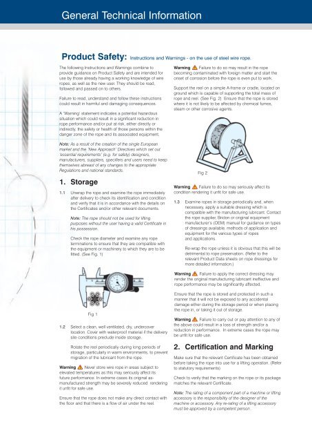
Support the reel on a simple A-frame or cradle, located on<br />
ground which is capable of supporting the total mass of<br />
<strong>rope</strong> and reel. (See Fig. 2) Ensure that the <strong>rope</strong> is stored<br />
where it is not likely to be affected by chemical fumes,<br />
steam or other corrosive agents.<br />
Note: As a result of the creation of the single Eu<strong>rope</strong>an<br />
market and the ‘New Approach’ Directives which set out<br />
‘essential requirements’ (e.g. for <strong>safety</strong>) designers,<br />
manufacturers, suppliers, specifiers and users need to keep<br />
themselves abreast of any changes to the appropriate<br />
Regulations and national standards.<br />
1. Storage<br />
1.1 Unwrap the <strong>rope</strong> and examine the <strong>rope</strong> immediately<br />
after delivery to check its identification and condition<br />
and verify that it is in accordance with the details on<br />
the Certificates and/or other relevant documents.<br />
Note: The <strong>rope</strong> should not be used for lifting<br />
purposes without the user having a valid Certificate in<br />
his possession.<br />
Check the <strong>rope</strong> diameter and examine any <strong>rope</strong><br />
terminations to ensure that they are compatible with<br />
the equipment or machinery to which they are to be<br />
fitted. (See Fig. 1)<br />
Fig 2<br />
Warning Failure to do so may seriously affect its<br />
condition rendering it unfit for safe use.<br />
1.3 Examine <strong>rope</strong>s in storage periodically and, when<br />
necessary, apply a suitable dressing which is<br />
compatible with the manufacturing lubricant. Contact<br />
the <strong>rope</strong> supplier, <strong>Bridon</strong> or original equipment<br />
manufacturer’s (OEM) manual for guidance on types<br />
of dressings available, methods of application and<br />
equipment for the various types of <strong>rope</strong>s<br />
and applications.<br />
Re-wrap the <strong>rope</strong> unless it is obvious that this will be<br />
detrimental to <strong>rope</strong> preservation. (Refer to the<br />
relevant Product Data sheets on <strong>rope</strong> dressings for<br />
more detailed information.)<br />
Warning Failure to apply the correct dressing may<br />
render the original manufacturing lubricant ineffective and<br />
<strong>rope</strong> performance may be significantly affected.<br />
Fig 1<br />
1.2 Select a clean, well ventilated, dry, undercover<br />
location. Cover with waterproof material if the delivery<br />
site conditions preclude inside storage.<br />
Rotate the reel periodically during long periods of<br />
storage, particularly in warm environments, to prevent<br />
migration of the lubricant from the <strong>rope</strong>.<br />
Warning Never store <strong>wire</strong> <strong>rope</strong> in areas subject to<br />
elevated temperatures as this may seriously affect its<br />
future performance. In extreme cases its original asmanufactured<br />
strength may be severely reduced rendering<br />
it unfit for safe use.<br />
Ensure that the <strong>rope</strong> does not make any direct contact with<br />
the floor and that there is a flow of air under the reel.<br />
Ensure that the <strong>rope</strong> is stored and protected in such a<br />
manner that it will not be exposed to any accidental<br />
damage either during the storage period or when placing<br />
the <strong>rope</strong> in, or taking it out of storage.<br />
Warning Failure to carry out or pay attention to any of<br />
the above could result in a loss of strength and/or a<br />
reduction in performance. In extreme cases the <strong>rope</strong> may<br />
be unfit for safe use.<br />
2. Certification and Marking<br />
Make sure that the relevant Certificate has been obtained<br />
before taking the <strong>rope</strong> into use for a lifting operation. (Refer<br />
to statutory requirements)<br />
Check to verify that the marking on the <strong>rope</strong> or its package<br />
matches the relevant Certificate.<br />
Note: The rating of a component part of a machine or lifting<br />
accessory is the responsibility of the designer of the<br />
machine or accessory. Any re-rating of a lifting accessory<br />
must be approved by a competent person.
General Technical Information<br />
Retain the Certificate in a safe place for identification of the<br />
<strong>rope</strong> when carrying out subsequent periodic statutory<br />
examinations in service. (Refer to statutory requirements)<br />
3. Handling and Installation<br />
3.1 Handling and installation of the <strong>rope</strong> should be<br />
carried out in accordance with a detailed plan and<br />
should be supervised by a competent person.<br />
Drum<br />
Check the general condition of the drum.<br />
If the drum is grooved, check the radius and pitch and<br />
ensure that the grooves will satisfactorily accommodate<br />
the size of the new <strong>rope</strong> (see Fig 3)<br />
PITCH<br />
Warning Incorrectly supervised handling and<br />
installation procedures may result in serious injury to<br />
persons in the vicinity of the operation as well as those<br />
persons directly involved in the handling and installation.<br />
RADIUS<br />
3.2 Wear suitable protective clothing such as overalls,<br />
industrial gloves, helmet, eye protectors and <strong>safety</strong><br />
footwear (and respirator, particularly where the<br />
emission of fumes due to heat is likely).<br />
Warning Failure to wear suitable protective clothing<br />
and equipment may result in skin problems from over<br />
exposure to certain types of <strong>rope</strong> lubricants and<br />
dressings; burns from sparks, <strong>rope</strong> ends, molten<br />
lubricants and metals when cutting <strong>rope</strong>s or preparing<br />
sockets for re-use; respiratory or other internal problems<br />
from the inhalation of fumes when cutting <strong>rope</strong>s or<br />
preparing sockets for re-use; eye injuries from sparks<br />
when cutting <strong>rope</strong>s; lacerations to the body from <strong>wire</strong> and<br />
<strong>rope</strong> ends; bruising of the body and damage to limbs due<br />
to <strong>rope</strong> recoil, backlash and any sudden deviation from<br />
the line of path of <strong>rope</strong>.<br />
3.3 Ensure that the correct <strong>rope</strong> has been supplied by<br />
checking to see that the description on the<br />
Certificate is in accordance with that specified in the<br />
purchaser’s order.<br />
3.4 Check by measurement that the nominal diameter of<br />
the new <strong>rope</strong> conforms to the nominal size stated on<br />
the Certificate.<br />
For verification purposes, measure the diameter by<br />
using a suitable <strong>rope</strong> vernier fitted with jaws broad<br />
enough to cover not less than two adjacent strands.<br />
Take two sets of measurements spaced at least 1<br />
metre apart, ensuring that they are taken at the<br />
largest cross-sectional dimension of the <strong>rope</strong>.<br />
At each point take measurements at right angles to<br />
each other.<br />
The average of these four measurements should be<br />
within the tolerances specified in the appropriate<br />
Standard or Specification.<br />
For a more general assessment of <strong>rope</strong> diameter<br />
use a <strong>rope</strong> calliper. (See Fig 1)<br />
3.5 Examine the <strong>rope</strong> visually to ensure that no damage<br />
or obvious signs of deterioration have taken place<br />
during storage or transportation to the<br />
installation site.<br />
Fig 3<br />
Check the condition and position of the kicker plates or<br />
wear plates, if fitted, to ensure that the new <strong>rope</strong> will spool<br />
correctly on the drum.<br />
Sheaves<br />
Ensure that the grooving is of the correct shape and size<br />
for the new <strong>rope</strong><br />
Check that all sheaves are free to rotate and in<br />
good condition.<br />
Rope guards<br />
Check that any <strong>rope</strong> guards are correctly fitted and are in<br />
good condition.<br />
Check the condition of any wear plates or rollers which are<br />
protecting structural members.<br />
Warning Failure to carry out any of the above could<br />
result in unsatisfactory and unsafe <strong>rope</strong> performance.<br />
Note: Grooves must have clearance for the <strong>rope</strong> and<br />
provide adequate circumferential support to allow for free<br />
movement of the strands and facilitate bending. When<br />
grooves become worn and the <strong>rope</strong> is pinched at the<br />
sides, strand and <strong>wire</strong> movement is restricted and the<br />
ability of the <strong>rope</strong> to bend is reduced. (See Fig. 4)<br />
Fig 4<br />
WRONG<br />
Sheave groove too narrow<br />
WRONG<br />
Sheave groove too wide<br />
RIGHT<br />
Sheave groove correctly<br />
supporting the <strong>rope</strong> for<br />
33% of its circumference<br />
3.6 Check the working area around the equipment for<br />
any potential hazards which may affect the safe<br />
installation of the <strong>rope</strong>.<br />
3.7 Check the condition of the <strong>rope</strong>-related equipment in<br />
accordance with the OEM’s instructions. Include the<br />
following -
General Technical Information<br />
When a new <strong>rope</strong> is fitted, a variation in size compared<br />
with the old worn <strong>rope</strong> will be apparent. The new <strong>rope</strong> may<br />
not fit correctly into the previously worn groove profile and<br />
unnecessary wear and <strong>rope</strong> distortion is likely to occur.<br />
This may be remedied by machining out the grooves<br />
before the new <strong>rope</strong> is installed. Before carrying out such<br />
action the sheaves or drum should be examined to ensure<br />
that there will be sufficient strength remaining in the<br />
underlying material to safely support the <strong>rope</strong>.<br />
The competent person should be familiar with the<br />
requirements of the appropriate application/machinery<br />
standard.<br />
Transfer the <strong>wire</strong> <strong>rope</strong> carefully from the storage area to the<br />
installation site.<br />
Coils<br />
Place the coil on the ground and roll it out straight<br />
ensuring that it does not become contaminated with<br />
dust/grit, moisture or any other harmful material.<br />
- Position the reel and stand such that the fleet angle<br />
during installation is limited to 1.5 degrees.<br />
(See Fig. 7)<br />
ANGLE OF<br />
FLEET<br />
CENTRE LINE<br />
OF REEL<br />
CENTRE LINE<br />
OF SHEAVE<br />
Fig 7<br />
- If a loop forms in the <strong>rope</strong><br />
ensure that it does not tighten<br />
to form a kink.<br />
Warning A kink can<br />
severely affect the strength<br />
of a six strand <strong>rope</strong> and can<br />
result in distortion of a<br />
rotation- resistant or low<br />
rotation <strong>rope</strong> leading to its<br />
immediate discard.<br />
Ensure that the reel stand is<br />
mounted so as not to create<br />
a reverse bend during reeving<br />
(i.e. for a winch drum with an<br />
overlap <strong>rope</strong>, take the <strong>rope</strong> off<br />
the top of the reel). (See Fig. 8)<br />
(See Fig. 5)<br />
Fig 8<br />
Fig 8<br />
Fig 5<br />
If the coil is too large to physically handle it may be placed<br />
on a ‘swift’ turntable and the outside end of the <strong>rope</strong><br />
pulled out allowing the coil to rotate.<br />
(See Fig. 5)<br />
Warning Never pull a <strong>rope</strong> away from a stationary coil<br />
as this will induce turn into the <strong>rope</strong> and kinks will form.<br />
These will adversely affect <strong>rope</strong> performance.<br />
(See Fig. 6)<br />
Fig 6<br />
Wrong<br />
Note the kinks<br />
forming<br />
3.9<br />
Ensure that any equipment or machinery to be <strong>rope</strong>d<br />
is correctly and safely positioned and isolated from<br />
normal usage before installation commences. Refer<br />
to the OEM’s instruction manual and the relevant<br />
‘Code of Practice’.<br />
3.10 When releasing the outboard end of the <strong>rope</strong> from a<br />
reel or coil, ensure that this is done in a controlled<br />
manner. On release of the bindings and servings<br />
used for packaging, the <strong>rope</strong> will want to straighten<br />
itself from its previously bent position. Unless<br />
controlled, this could be a violent action. Stand clear.<br />
Reels<br />
Pass a shaft through the reel and place the reel in a suitably<br />
ancherded stand which allows it to rotate and be braked to<br />
avoid overrun during installation. Where multi-layer coiling is<br />
involved it may be necessary for the reel to be placed in<br />
equipment which has the capability of providing a back<br />
tension in the <strong>rope</strong> as it is being transferred from reel to<br />
drum. This is to ensure that the underlying (and<br />
subsequent) laps are wound tightly on the drum.<br />
(See Fig. 7)
General Technical Information<br />
Warning<br />
Failure to control could result in injury.<br />
Ensure that the as-manufactured condition of the<br />
<strong>rope</strong> is maintained during installation.<br />
If installing the new <strong>rope</strong> with the aid of an old one,<br />
one method is to fit a <strong>wire</strong> <strong>rope</strong> sock (or stocking) to<br />
each of the <strong>rope</strong> ends. Always ensure that the open<br />
end of the sock (or stocking) is securely attached to<br />
the <strong>rope</strong> by a serving or alternatively by a clip (See<br />
Fig. 9). Connect the two ends via a length of fibre<br />
<strong>rope</strong> of adequate strength in order to avoid turn<br />
being transmitted from the old <strong>rope</strong> into the new<br />
<strong>rope</strong>. Alternatively a length of fibre or steel <strong>rope</strong> of<br />
adequate strength may be reeved into the system<br />
for use as a pilot/messenger line. Do not use a<br />
swivel during the installation of the <strong>rope</strong>.<br />
3.11 Monitor the <strong>rope</strong> carefully as it is being pulled into<br />
the system and make sure that it is not obstructed<br />
by any part of the structure or mechanism which<br />
may cause the <strong>rope</strong> to come free.<br />
Warning Failure to monitor during this operation could<br />
result in injury.<br />
This entire operation should be carried out carefully<br />
and slowly under the supervision of a competent<br />
person.<br />
3.12 Take particular care and note the manufacturer’s<br />
instructions when the <strong>rope</strong> is required to be cut.<br />
Apply secure servings on both sides of the cut mark.<br />
Ensure that the length of serving is at least equal to<br />
two <strong>rope</strong> diameters. (Note: Special servings are<br />
required for spiral <strong>rope</strong>s, i.e. spiral strand and<br />
locked coil.)<br />
One serving either side of the cut is normally<br />
sufficient for preformed <strong>rope</strong>s. For non-preformed<br />
<strong>rope</strong>s, rotation-resistant <strong>rope</strong>s and parallel closed<br />
<strong>rope</strong>s (e.g. DSC 8 <strong>rope</strong>s) a minimum of two servings<br />
each side of the cut will be necessary (See Fig. 10).<br />
Arrange and position the <strong>rope</strong> in such a manner that<br />
at the completion of the cutting operation the <strong>rope</strong><br />
ends will remain in position, thus avoiding any<br />
backlash or any other undesirable movement.<br />
Cut the <strong>rope</strong> with a high speed abrasive disc cutter.<br />
Other suitable mechanical or hydraulic shearing<br />
equipment may be used although not recommended<br />
when a <strong>rope</strong> end is required to be welded or brazed.<br />
Warning When using a disc cutter be aware of the<br />
danger from sparks, disc fragmentation and fumes.<br />
(Refer 3.2.)<br />
Ensure adequate ventilation to avoid any build-up of<br />
fumes from the <strong>rope</strong> and its constituent parts including any<br />
fibre core (natural or synthetic) any <strong>rope</strong> lubricant(s) and<br />
any synthetic filling and/or covering material.<br />
Warning Some special <strong>rope</strong>s contain synthetic<br />
material which, when heated to a temperature higher than<br />
normal production processing temperatures, will<br />
decompose and may give off toxic fumes.<br />
Warning Rope produced from carbon steel <strong>wire</strong>s in<br />
the form shipped is not considered a health hazard. During<br />
subsequent processing (e.g. cutting, welding, grinding,<br />
cleaning) dust and fumes may be produced which contain<br />
elements which may affect<br />
exposed workers.<br />
The products used in the manufacture of steel <strong>wire</strong> <strong>rope</strong>s<br />
for lubrication and protection present minimal hazard to<br />
the user in the form shipped. The user must however, take<br />
reasonable care to minimise skin and eye contact and also<br />
avoid breathing their vapour and mist.<br />
After cutting, the <strong>rope</strong> cross-sections of nonpreformed<br />
<strong>rope</strong>s, rotation-resistant <strong>rope</strong>s and parallel<br />
closed <strong>rope</strong>s must be welded, brazed or fused and<br />
tapered such that all <strong>wire</strong>s and strands in the <strong>rope</strong> are<br />
completely secured.<br />
Warning Failure to correctly secure the <strong>rope</strong> end is<br />
likely to lead to slackness, distortions, premature removal<br />
from service and a reduction in the breaking force of<br />
the <strong>rope</strong>.<br />
3.13 Ensure that any fittings such as clamps or fixtures<br />
are clean and undamaged before securing <strong>rope</strong><br />
ends.<br />
Make sure that all fittings are secure in accordance<br />
with the OEM’s instruction manual or manufacturer’s<br />
instructions and take particular note of any specific<br />
<strong>safety</strong> requirements e.g. torque values (and<br />
frequency of any re-application of torque).<br />
Fig 10<br />
When terminating a <strong>rope</strong> end with a wedge socket,<br />
ensure that the <strong>rope</strong> tail cannot withdraw through the<br />
socket by securing a clamp to the tail or by following<br />
the manufacturer’s instructions.<br />
For some applications, and depending on the <strong>rope</strong><br />
type, minimum lengths of tails are specified. Refere<br />
to the appropriate codes of practise or Regulations<br />
Fig 9<br />
(See Fig. 11 for two recommended methods of<br />
securing the <strong>rope</strong> tail of a wedge socket<br />
termination).
General Technical Information<br />
The loop back method uses a<br />
<strong>rope</strong> grip and the loop should<br />
be lashed to the live part of<br />
<strong>rope</strong> by a soft <strong>wire</strong> serving or<br />
tape to prevent flexing of the<br />
<strong>rope</strong> in service.<br />
P<strong>rope</strong>r method of locating <strong>rope</strong> anchorage point<br />
on a plain drum<br />
RIGHT HAND<br />
LAY ROPE-<br />
UNDERWIND<br />
The method of looping back<br />
should not be used if there is<br />
a possibility of interference of<br />
the loop with the mechanism<br />
or structure.<br />
START ROPE<br />
AT LEFT<br />
FLANGE<br />
RIGHT<br />
HAND<br />
RIGHT HAND<br />
LAY ROPE-<br />
OVERWIND<br />
Fig 11<br />
Warning Failure to<br />
secure in accordance with<br />
instructions could lead to<br />
loss of the <strong>rope</strong><br />
and/or injury.<br />
3.14 When coiling a <strong>rope</strong> on<br />
a plain (or smooth) barrel<br />
drum ensure that each lap<br />
lies tightly against the<br />
preceding lap. The<br />
application of tension in the<br />
<strong>rope</strong> greatly assists in the<br />
coiling of the <strong>rope</strong>.<br />
Warning Any looseness<br />
or uneven winding will result<br />
in excessive wear, crushing<br />
and distortion of the <strong>rope</strong>.<br />
With plain barrel drums it is<br />
difficult to achieve<br />
satisfactory multi-layer coiling<br />
beyond three layers.<br />
The direction of coiling of the<br />
<strong>rope</strong> on the drum is<br />
important, particularly when<br />
using plain barrel drums, and<br />
should be related to the<br />
direction of lay of the <strong>rope</strong> in<br />
order to induce<br />
close coiling.<br />
(See Fig. 12 for p<strong>rope</strong>r method of locating <strong>rope</strong><br />
anchorage point on a plain drum.)<br />
When multi layer coiling has to be used it should be<br />
realised that after the first layer is wound on a drum,<br />
the <strong>rope</strong> has to cross the underlying <strong>rope</strong> in order to<br />
advance across the drum in the second layer. The<br />
points at which the turns in the upper layer cross<br />
those of the lower layer are known as the cross-over<br />
points and the <strong>rope</strong> in these areas is susceptible to<br />
increased abrasion and crushing. Care should be<br />
taken when installing a <strong>rope</strong> on a drum and when<br />
operating a machine to ensure that the <strong>rope</strong> is<br />
coiled and layered correctly.<br />
3.15 Check the state of re-usable <strong>rope</strong> end terminations<br />
for size, strength, defects and cleanliness before<br />
use. Non-destructive testing may be required<br />
depending on the material and circumstances of<br />
use. Ensure that the termination is fitted in<br />
accordance with the OEM’s instruction manual or<br />
manufacturer’s instructions.<br />
LEFT<br />
HAND<br />
LEFT<br />
HAND<br />
LEFT HAND<br />
LAY ROPE-<br />
UNDERWIND<br />
LEFT HAND<br />
LAY ROPE-<br />
OVERWIND<br />
Note: Thumb indicates side of <strong>rope</strong> anchorage<br />
Fig 12<br />
When re-using a socket and depending on its type<br />
and dimensions, the existing cone should be<br />
pressed out. Otherwise, heat may be necessary.<br />
Warning When melting out sockets which have<br />
previously been filled with hot metal, the emission of toxic<br />
fumes is likely. Note that white metal contains a high<br />
proportion of lead.<br />
Correctly locate and secure any connection pins and<br />
fittings when assembling end terminations to<br />
fixtures. Refer to manufacturer’s instructions.<br />
Warning Failure to pay attention to any of the above<br />
could result in unsafe operation and potential injury.<br />
3.16 Limit switches, if fitted, must be checked and<br />
re-adjusted, if necessary, after the <strong>rope</strong> has been<br />
installed.<br />
3.17 Record the following details on the Certificate after<br />
installation has been completed: type of equipment,<br />
location, plant reference number, duty and date of<br />
installation and any re-rating information/signature of<br />
competent person. Then safely file the Certificate.<br />
3.18 ‘Run in’ the new <strong>rope</strong> by operating the equipment<br />
slowly, preferably with a low load, for several cycles.<br />
This permits the new <strong>rope</strong> to adjust itself gradually to<br />
working conditions.<br />
Note: Unless otherwise required by a certifying<br />
authority, the <strong>rope</strong> should be in this condition before<br />
any proof test of the equipment or machinery is<br />
carried out.
General Technical Information<br />
Check that the new <strong>rope</strong> is spooling correctly on the<br />
drum and that no slack or cross laps develop. Apply<br />
a back tension in the order of 2% to 5% of the<br />
strength of the <strong>rope</strong> in order to acheive tight and<br />
even coiling especially on the first layer..<br />
Where multi-layer coiling is unavoidable, succeeding<br />
layers should coil evenly on the preceding layers<br />
of <strong>rope</strong>.<br />
Warning Irregular coiling usually results in severe<br />
surface wear and <strong>rope</strong> malformation, which in turn is likely<br />
to cause premature <strong>rope</strong> failure.<br />
3.19 Ensure that the as-manufactured condition of the<br />
<strong>rope</strong> is maintained throughout the whole of the<br />
handling and installation operation.<br />
3.20 If samples are required to be taken from the <strong>rope</strong> for<br />
subsequent testing and/or evaluation, it is essential<br />
that the condition of the <strong>rope</strong> is not disturbed. Refer<br />
to the instructions given in 3.12 and, depending on<br />
the <strong>rope</strong> type and construction, any other special<br />
manufacturer’s instructions.<br />
4. In Service<br />
4.1 Inspect the <strong>rope</strong> and related equipment at the<br />
beginning of every work period and particularly<br />
following any incident which could have damaged<br />
the <strong>rope</strong> or installation.<br />
Fig 13<br />
The entire length of <strong>rope</strong> should be inspected and<br />
particular attention paid to those sections that<br />
experience has proven to be the main areas of<br />
deterioration. Excessive wear, broken <strong>wire</strong>s,<br />
distortion and corrosion are the usual signs of<br />
deterioration. For a more detailed examination<br />
special tools are necessary (see Fig. 13) which will<br />
also facilitate internal inspection (see Fig. 14.)<br />
There are however, mixed feeling about the wisdom<br />
of opening up <strong>rope</strong>s. Not withstanding this, not all<br />
<strong>rope</strong>s can be opened up due to there size and<br />
construction. In any case, the decision as to whether<br />
a <strong>rope</strong> should be opened up should be left to the<br />
discretion of the competent person.<br />
In the case of <strong>rope</strong>s working over drums or sheaves<br />
it is particularly necessary to examine those areas<br />
entering or leaving the grooves when maximum<br />
loads (i.e. shock loads) are experienced, or those<br />
areas which remain for long periods in exposed<br />
places such as over a jib head sheave.<br />
On some running <strong>rope</strong>s, but particularly relevant to<br />
standing <strong>rope</strong>s (e.g. pendant <strong>rope</strong>s) the areas<br />
adjacent to terminations should be given special<br />
attention (see Fig. 14).<br />
When a non-preformed <strong>rope</strong>,<br />
rotation-resistant <strong>rope</strong> or<br />
parallel closed <strong>rope</strong> (i.e. DSC)<br />
is used with a wedge socket<br />
and is required to be shortened,<br />
it is essential that the end of the<br />
<strong>rope</strong> is secured by welding or<br />
brazing before the <strong>rope</strong> is<br />
pulled through the main body of<br />
the socket to its new position.<br />
Slacken the wedge in the<br />
socket. Pass the <strong>rope</strong> through<br />
the socket by an amount<br />
equivalent to the crop length or<br />
sample required. Note that the<br />
original bent portion of the <strong>rope</strong><br />
must not be retained within the<br />
wedge socket. Replace the<br />
Fig 14<br />
wedge and pull up the socket.<br />
Prepare and cut in accordance<br />
with section 3.12. Ensure that the <strong>rope</strong> tail cannot<br />
withdraw through the socket, see section 3.13.<br />
Warning Failure to observe this instruction will result in<br />
a significant deterioration in the performance of the <strong>rope</strong><br />
and could render the <strong>rope</strong> completely unfit for further<br />
service.<br />
In cases where severe <strong>rope</strong> wear takes place at<br />
one end of a <strong>wire</strong> <strong>rope</strong>, the life of the <strong>rope</strong> may be<br />
extended by changing round the drum end with the<br />
load end, i.e. turning the <strong>rope</strong> ‘end for end’ before<br />
deterioration becomes excessive.<br />
4.2 If at all possible remove broken <strong>wire</strong>s as they occur<br />
by bending backwards and forwards using a pair of<br />
pliers until they break deep in the valley between two<br />
outer strands (see Fig. 15). Wear protective clothing<br />
such as overalls, industrial gloves, helmet, eye<br />
protectors and <strong>safety</strong> footwear during this operation.<br />
Fig 15<br />
Warning Do not shear<br />
off the ends of broken <strong>wire</strong>s<br />
with pliers as this will leave<br />
an exposed jagged edge<br />
which is likely to damage<br />
other <strong>wire</strong>s in the <strong>rope</strong> and<br />
lead to premature removal of<br />
the <strong>rope</strong> from service.<br />
Failure to wear adequate<br />
protective clothing could<br />
result in injury.<br />
Note: Broken <strong>wire</strong>s are a<br />
normal feature of service, more<br />
so towards the end of the<br />
<strong>rope</strong>’s life, resulting from<br />
bending fatigue and wear. The<br />
local break up of <strong>wire</strong>s may<br />
indicate some mechanical fault<br />
in the equipment.<br />
Record the number and<br />
position in the <strong>rope</strong> of any<br />
removed broken <strong>wire</strong>s.<br />
Note: Shortening the <strong>rope</strong> re-positions the areas of<br />
maximum deterioration in the system. Where<br />
conditions permit, begin operating with a <strong>rope</strong> which<br />
has a slightly longer length than necessary in order<br />
to allow for periodic shortening.
General Technical Information<br />
4.3 Do not operate an appliance if for any reason (e.g.<br />
<strong>rope</strong> diameter, certified breaking force, <strong>rope</strong><br />
construction, length or strength and type of <strong>rope</strong><br />
termination) the <strong>wire</strong> <strong>rope</strong> and its termination is<br />
considered unsuitable for the required duty.<br />
4.4 Do not operate an appliance if the <strong>wire</strong> <strong>rope</strong> fitted<br />
has become distorted, been damaged or has<br />
deteriorated to a level such that discard criteria<br />
has been reached or is likely to be reached prior to<br />
normal expected life based on historical<br />
performance data.<br />
Warning Rope distortion is usually a result of<br />
mechanical damage and can significantly reduce <strong>rope</strong><br />
strength.<br />
4.5 An authorised competent person must examine the<br />
<strong>rope</strong> in accordance with the appropriate<br />
Regulations.<br />
4.6 Do not carry out any inspection, examination,<br />
dressing/lubrication, adjustment or any other<br />
maintenance of the <strong>rope</strong> whilst it is suspending<br />
a load, unless otherwise stated in the OEM’s<br />
instruction manual or other relevant documents.<br />
Do not carry out any inspection or maintenance of<br />
the <strong>rope</strong> if the appliance controls are unattended<br />
unless the surrounding area has been isolated or<br />
sufficient warning signs have been posted within<br />
the immediate vicinity.<br />
If the appliance controls are attended, the authorised<br />
person must be able to communicate effectively with<br />
the driver or controller of the appliance during the<br />
inspection process.<br />
4.7 Never clean the <strong>wire</strong> <strong>rope</strong> without recognising the<br />
potential hazards associated with working on a<br />
moving <strong>rope</strong>.<br />
Warning Failure to pay attention or take adequate<br />
precaution could result in injury.<br />
If cleaning by cloth/waste, the material can be<br />
snagged on damaged surfaces and/or broken <strong>wire</strong>s.<br />
If cleaning by brush, eye protectors must be worn.<br />
If using fluids it should be recognised that some<br />
products are highly inflammable. A respirator should<br />
be worn if cleaning by a pressurised spray system.<br />
Warning Failure to take adequate precaution could<br />
result in injury or damage to health.<br />
Only use compatible cleaning fluids which will not<br />
impair the original <strong>rope</strong> lubricant nor affect the <strong>rope</strong><br />
associated equipment.<br />
Warning The use of cleaning fluids (particularly<br />
solvent based) is likely to ‘cut back’ the existing <strong>rope</strong><br />
lubricant leading to a greater quantity of lubricant<br />
accumulating on the surface of the <strong>rope</strong>. This may<br />
create a hazard in appliances and machinery which rely on<br />
friction between the <strong>rope</strong> and the drive sheave (e.g. lifts,<br />
friction winders and cableways).<br />
4.8 Lubricants selected for in-service dressing must be<br />
compatible with the <strong>rope</strong> manufacturing lubricant<br />
and should be referenced in the OEM’s instruction<br />
manual or other documents approved by the owner<br />
of the appliance.<br />
If in doubt contact the <strong>rope</strong> supplier or <strong>Bridon</strong>.<br />
4.9 Take particular care when applying any in-service<br />
lubricant/dressing. Application systems which<br />
involve pressure should only be operated by trained<br />
and authorised persons and the operation carried<br />
out strictly in accordance with the manufacturer’s<br />
instructions.<br />
Most <strong>wire</strong> <strong>rope</strong>s should be lubricated as soon as<br />
they are put into service and at regular intervals<br />
thereafter (including cleaning) in order to extend<br />
safe performance.<br />
Warning A ‘dry’ <strong>rope</strong> unaffected by corrosion but<br />
subject to bend fatigue, is likely to achieve only 30% of<br />
that normally attained by a ‘lubricated’ <strong>rope</strong>.<br />
Do not dress/lubricate the <strong>rope</strong> if the application<br />
required it to remain dry. (Refer OEM’s<br />
instruction manual.)<br />
Reduce the period between examinations when<br />
<strong>rope</strong>s are not subjected to any in-service dressing<br />
and when they must remain dry.<br />
Note: The authorised person carrying out a <strong>rope</strong><br />
inspection must be capable of recognising the<br />
potential loss of safe performance of such a <strong>rope</strong><br />
in comparison with lubricated <strong>rope</strong>.<br />
Clean the <strong>rope</strong> before applying a fresh dressing/<br />
lubricant if it is heavily loaded with foreign matter<br />
e.g. sand, dust.<br />
4.10 The authorised person responsible for carrying out<br />
<strong>wire</strong> <strong>rope</strong> maintenance must ensure that the ends of<br />
the <strong>rope</strong> are secure. At the drum end this will involve<br />
checking the integrity of the anchorage and ensuring<br />
that there are at least two and a half dead laps<br />
tightly coiled. At the outboard end the integrity of<br />
the termination must be checked to ensure that it is<br />
in accordance with the OEM’s manual or other<br />
documents approved by the owner of the appliance.<br />
Adjust the lengths of <strong>rope</strong>s in multi-<strong>rope</strong> systems<br />
in order that equal forces (within approved limits)<br />
are evident.<br />
If a <strong>wire</strong> <strong>rope</strong> needs cutting refer to 3.12.<br />
When securing <strong>rope</strong> ends refer to 3.13.<br />
When re-usable end terminations are used refer<br />
to 3.15.<br />
When re-connecting any end terminations to fixtures<br />
refer to 3.15.
General Technical Information<br />
4.11 Warning Damage to, or removal of component<br />
parts (mechanical or structural) caused by abnormal<br />
contact with <strong>wire</strong> <strong>rope</strong> can be hazardous to the<br />
<strong>safety</strong> of the appliance and/or the performance of the<br />
<strong>rope</strong> (e.g. damage to the drum grooving, such that<br />
coiling is erratic and/or the <strong>rope</strong> is ‘pulled down’ into<br />
underlying layers, which might cause a dangerous<br />
condition or, alternatively, cause localised <strong>rope</strong><br />
damage at ‘cross-over’ positions, which might then<br />
radically affect performance; loss/removal of wear<br />
plates protecting the structure leading to major<br />
structural damage by cutting and/or failure of the <strong>wire</strong><br />
<strong>rope</strong> due to mechanical severance).<br />
4.12 Following any periodic statutory examination or<br />
routine or special inspection where any corrective<br />
action is taken the Certificate should be updated<br />
and a record made of the defects found, the extent<br />
of the changes and the condition of the <strong>rope</strong>.<br />
4.13 Apply the following procedures for the selection and<br />
preparation of samples, from new and used lengths<br />
of <strong>rope</strong>, for the purpose of examination and testing<br />
to destruction.<br />
Check that the <strong>rope</strong> end, from which the sample will<br />
be taken, is secured by welding or brazing. If not,<br />
select the sample length further away from the <strong>rope</strong><br />
end and prepare new servings.<br />
Handle the <strong>rope</strong> in accordance with the instructions<br />
given in section 3. Serve the <strong>rope</strong>, using the buried<br />
<strong>wire</strong> technique (see Fig. 10) and apply a <strong>rope</strong> clamp<br />
or grip as close to the cut mark as practically<br />
possible. Do not use solder to secure the servings.<br />
Ensure that the sample is kept straight throughout<br />
the whole procedure and ensure that the minimum<br />
sample length is 3 metres for <strong>rope</strong>s up to and<br />
including 40mm diameter and 12 metres for larger<br />
diameter <strong>rope</strong>s.<br />
The <strong>rope</strong> should be cut with a high speed abrasive<br />
disc cutter or an oxyacetylene torch. Weld the <strong>rope</strong><br />
ends of the sample as described in section 3.12,<br />
after which the clamp or grip can be removed.<br />
The identification of the <strong>rope</strong> must be established<br />
and the sample suitably marked and packed. It is<br />
recommended that the 3 metre sample is retained<br />
straight and secured to a wood batten for<br />
transportation. For a 12 metre sample, coil to a<br />
diameter as large as practically possible and never<br />
less than 2 metres.<br />
Note: Samples taken for destruction testing are<br />
required to be socketed with resin in accordance<br />
with a recognised standard e.g. EN13411-4.<br />
Warning Failure to comply with these procedures will<br />
result in measured breaking force values which are not<br />
truly representative of the actual strength of the <strong>rope</strong>.<br />
5. Wire Rope Discard<br />
5.1 Discard the <strong>wire</strong> <strong>rope</strong> in accordance with current<br />
Regulations and in accordance with the OEM’s<br />
instruction manual.<br />
5.2 If a <strong>wire</strong> <strong>rope</strong> is removed from service at a level of<br />
performance substantially different to historically<br />
established performance data, the reason for this<br />
should be investigated.<br />
5.3 Only qualified and experienced personnel, taking the<br />
appropriate <strong>safety</strong> precautions and wearing the<br />
appropriate protective clothing, should be<br />
responsible for removing the <strong>wire</strong> <strong>rope</strong>.<br />
Warning Take particular care when removing <strong>rope</strong>s<br />
with mechanical damage as they may fail abruptly during<br />
the change-out procedure.<br />
Take the utmost care when removing ‘exhausted/<br />
failed’ <strong>rope</strong>s from drums and sheaves as they may<br />
be grossly distorted, lively and tightly coiled.<br />
Warning Failure to take adequate precautions could<br />
result in injury.<br />
5.4 Store discarded <strong>rope</strong> in a safe and secure location<br />
or compound and ensure that it is suitably marked<br />
to identify it as <strong>rope</strong> which has been removed from<br />
service and not to be used again.<br />
Warning Discarded <strong>rope</strong> can be a danger (e.g.<br />
protruding broken <strong>wire</strong>s, excessive grease/lubricant and<br />
<strong>rope</strong> mass) to personnel and equipment if not handled<br />
correctly and safely during disposal.<br />
5.5 Record the date and reason for discard on the<br />
Certificate before filing for future reference.<br />
5.6 Pay attention to any Regulations affecting the safe<br />
disposal of steel <strong>wire</strong> <strong>rope</strong>.<br />
6. Rope Selection Criteria<br />
Ensure that the correct type of <strong>wire</strong> <strong>rope</strong> is selected<br />
for the equipment by referring to the OEM’s<br />
instruction manual or other relevant documents. If in<br />
doubt contact <strong>Bridon</strong> or <strong>Bridon</strong>’s distributor<br />
for guidance.<br />
6.1Rope Strength<br />
If necessary, refer to the appropriate Regulations<br />
and/or application standards and calculate the<br />
maximum force to which the <strong>rope</strong> will be subjected.<br />
The calculation may take into account the mass to<br />
be lifted or moved, any shock loading, effects of high<br />
speed, acceleration, any sudden starts or stops,<br />
frequency of operation and sheave bearing friction.<br />
By applying the relevant coefficient of utilisation/<br />
<strong>safety</strong> factor/design factor and, where applicable,<br />
the efficiency of the <strong>rope</strong> termination, the required<br />
minimum breaking load or force of the <strong>rope</strong> will be<br />
determined, the values of which are available from the<br />
relevant National, Eu<strong>rope</strong>an or International standards<br />
or from specific Product Data literature. If in doubt ask<br />
for advice from <strong>Bridon</strong> or <strong>Bridon</strong>’s distributor.
General Technical Information<br />
6.2Bending fatigue<br />
The size and number of sheaves in the system will<br />
influence the performance of the <strong>rope</strong>.<br />
Warning Wire <strong>rope</strong> which bends around sheaves,<br />
rollers or drums will deteriorate through ‘bending fatigue’.<br />
Reverse bending and high speed will accelerate the<br />
process. Therefore, under such conditions select a <strong>rope</strong><br />
with high bending fatigue resistance. Refer to Product<br />
Data Information, and if in doubt ask for advice.<br />
6.3Abrasion<br />
Wire <strong>rope</strong> which is subject to abrasion will become<br />
progressively weaker as a result of:<br />
Externally - dragging it through overburden, sand or<br />
other abrasive materials and passing around a<br />
sheave, roller or drum.<br />
Internally - being loaded or bent.<br />
Warning Abrasion weakens the <strong>rope</strong> by removing<br />
metal from both the inner and outer <strong>wire</strong>s. Therefore, a<br />
<strong>rope</strong> with large outer <strong>wire</strong>s should normally be selected.<br />
6.4Vibration<br />
Vibration in <strong>wire</strong> <strong>rope</strong> will cause deterioration. This<br />
may become apparent in the form of <strong>wire</strong> fractures<br />
where the vibration is absorbed.<br />
Warning These fractures may be internal only and will<br />
not be visually identified.<br />
6.5Distortion<br />
Wire <strong>rope</strong> can be distorted due to high pressure<br />
against a sheave, imp<strong>rope</strong>rly sized grooves or as a<br />
result of multi-layer coiling on a drum.<br />
Rope with a steel core is more resistant to crushing<br />
and distortion.<br />
6.6Corrosion<br />
Rope with a large number of small <strong>wire</strong>s is more<br />
susceptible to corrosion than <strong>rope</strong> with a small<br />
number of large <strong>wire</strong>s. Therefore, if corrosion is<br />
expected to have a significant effect on <strong>rope</strong><br />
performance select a galvanised <strong>rope</strong> with as large<br />
an outer <strong>wire</strong> size as possible bearing in mind the<br />
other conditions (e.g. bending and abrasion)<br />
under which the <strong>rope</strong> will be operating.<br />
6.8Fixing of Rope Ends<br />
Ropes which have high rotation characteristics<br />
(such as single layer Lang’s lay <strong>rope</strong> and parallel<br />
closed <strong>rope</strong> e.g. DSC) must not be selected unless<br />
both ends of the <strong>rope</strong> are fixed or the load is guided<br />
and unable to rotate.<br />
Warning Failure to heed this warning could result in<br />
catastrophic failure particularly at a termination which is<br />
capable of being pulled apart (i.e. splice) due to unlaying.<br />
6.10 Rope Length<br />
Rope length and /or difference in length between<br />
two or more <strong>rope</strong>s used in a set may be a critical<br />
factor and must be considered along with <strong>rope</strong><br />
selection.<br />
Warning Wire <strong>rope</strong> will elongate under load. Other<br />
factors such as temperature, <strong>rope</strong> rotation and internal<br />
wear will also have an effect. These factors should also be<br />
considered during <strong>rope</strong> selection.<br />
6.11 Preformed and<br />
Non-preforme Ropes<br />
Single layer round strand <strong>rope</strong> is normally supplied<br />
preformed. However, if a non-preformed <strong>rope</strong> is<br />
selected then personnel responsible for its<br />
installation and/or maintenance need to take<br />
particular care when handling such <strong>rope</strong>, especially<br />
when cutting. For the purposes of this instruction,<br />
rotation-resistant, parallel closed and spiral <strong>rope</strong>s<br />
should be regarded as non-preformed <strong>rope</strong>s.<br />
6.12 Operating Temperatures<br />
Wire <strong>rope</strong> with a steel core should be selected if<br />
there is any evidence to suggest that a fibre core will<br />
not provide adequate support to the outer strands<br />
and/or if the temperature of the working environment<br />
may be expected to exceed 100˚C.<br />
For operating temperatures above 100˚C de-rating<br />
of the minimum breaking force of the <strong>rope</strong> is<br />
necessary (e.g. between 100˚C and 200˚C reduce<br />
by 10%; between 200˚C and 300˚C reduce by 25%;<br />
between 300˚C and 400˚C reduce by 35%).<br />
Do not use <strong>rope</strong>s with high carbon <strong>wire</strong>s above<br />
400˚C.<br />
Warning Failure to observe this general guidance<br />
could result in failure of the <strong>rope</strong>s to support the load.<br />
For temperatures over 400˚C, other materials such<br />
as stainless steel or other special alloys should be<br />
considered.<br />
Warning Rope lubricants and any synthetic filling<br />
and/or covering materials may become ineffective at<br />
certain low or high operating temperature levels.<br />
Certain types of <strong>rope</strong> end terminations also have<br />
limiting operating temperatures and the<br />
manufacturer or <strong>Bridon</strong> should be consulted where<br />
there is any doubt. Ropes with steel sores<br />
terminated with aluminium ferrules must not be used<br />
at temperatures in excess of 150˚C.<br />
6.9Connecting Ropes<br />
In the event that it is necessary to connect one <strong>rope</strong><br />
to another (in series) it is essential that they have<br />
the required strength, are of the same type and both<br />
have the same lay direction (i.e. connect ‘right’ lay<br />
to ‘right’ lay).
General Technical Information<br />
Warning<br />
Wire <strong>rope</strong> will fail if worn-out, shock loaded, overloaded, misused,<br />
damaged, imp<strong>rope</strong>rly maintained or abused.<br />
• Always inspect <strong>wire</strong> <strong>rope</strong> for wear, damage or abuse before use<br />
• Never use <strong>wire</strong> <strong>rope</strong> which is worn-out, damaged or abused<br />
• Never overload or shock load a <strong>wire</strong> <strong>rope</strong><br />
• Inform yourself: Read and understand the guidance on product <strong>safety</strong><br />
given in this catalogue; also read and understand the machinery<br />
manufacturer’s handbook<br />
• Refer to applicable directives, regulations, standards and codes<br />
concerning inspection, examination and <strong>rope</strong> removal criteria<br />
Protect yourself and others - failure of <strong>wire</strong> <strong>rope</strong> may cause serious injury<br />
or death!<br />
Warning<br />
CAUTIONARY NOTICE – RESTRICTIONS ON THE USE OF LARGE DIAMETER ROTATION-RESISTANT ROPES.<br />
All <strong>wire</strong> <strong>rope</strong>s are prone to damage if they are not p<strong>rope</strong>rly supported when used at high loads. Larger rotation-resistant<br />
<strong>rope</strong>s are particularly susceptible to this form of abuse, due to their rigid construction and the relatively fine <strong>wire</strong> sizes<br />
involved in their manufacture/construction. Instances have been recorded of <strong>rope</strong>s being heavily worked over plain drums<br />
and failing "prematurely", despite the nominal tension being in the region of half the breaking strength of the <strong>rope</strong>.<br />
The best way of preventing difficulties of this sort is to avoid conditions that are likely to generate damagingly high contact<br />
stresses. A simple method of assessing the severity of the contact conditions is to firstly calculate the tread pressure<br />
based on the projected nominal area and then apply a factor (of say 10*) to allow for the highly localised and intermittent<br />
nature of the actual <strong>wire</strong> contacts, as indicated below :-<br />
Type of contact Close-fitting U-groove Oversize U-groove Plain drum<br />
Level of support Good Fair Poor<br />
Tread path width 100% of <strong>rope</strong> dia. 50% of <strong>rope</strong> dia. 20% of <strong>rope</strong> dia.<br />
Tread pressure = 2T/Dd 4T/Dd 10T/Dd<br />
Contact stress = 20T/Dd 40T/Dd 100T/Dd<br />
Note: Contact stresses which exceed 10% of the tensile strength grade of the outer <strong>wire</strong>s should be<br />
considered a cause for concern, especially if the <strong>rope</strong> is operating at a low factor of <strong>safety</strong>.<br />
[* - This is because the true contact area is very much less than the projected nominal area.]<br />
Worked example:<br />
Consider case of a 50mm rotation-resistant <strong>rope</strong> (MBF=2100kN) operating at a 3:1 factor of <strong>safety</strong>.<br />
Then, for the Contact stress < 200 Mpa say, the following minimum bending diameters are indicated :-<br />
Close-fitting groove - 1400mm<br />
Oversize U-groove - 2800mm<br />
Plain drum - 7000mm
General Technical Information<br />
Material Safety Data<br />
Introduction<br />
Steel <strong>wire</strong> <strong>rope</strong> is a composite material and dependent<br />
upon its type may contain a number of discrete materials.<br />
The following provides full details of all the individual<br />
materials which may form part of the finished <strong>wire</strong> <strong>rope</strong>.<br />
The description and/or designation of the <strong>wire</strong> <strong>rope</strong> stated<br />
on the delivery note and/or invoice (or certificate, when<br />
applicable) will enable identification of the component parts.<br />
The main component of a steel <strong>wire</strong> <strong>rope</strong> is the <strong>wire</strong>, which<br />
may be carbon steel, coated (zinc or Zn95/A15) steel or<br />
stainless steel.<br />
The other three components are (i) the core, which may be<br />
of steel of the same type as used in the main strands or<br />
alternatively fibre (either natural or synthetic), (ii) the <strong>rope</strong><br />
lubricant and, where applicable, (iii) any internal filling or<br />
external covering. No Occupational Exposure Limits<br />
(OEL’s) exist for steel <strong>wire</strong> <strong>rope</strong> and the values provided in<br />
this publication relate to component elements and<br />
compounds. The actual figures quoted in relation to the<br />
component parts are taken from the latest edition of EH40.<br />
Rope produced from carbon, coated or stainless steel<br />
<strong>wire</strong>s in the as-supplied condition is not considered a<br />
health hazard. However during any subsequent processing<br />
such as cutting, welding, grinding and cleaning, dust and<br />
fumes may be produced which contain elements that may<br />
affect exposed workers.<br />
The following indicates the order in which specific<br />
information is provided:-<br />
Carbon steel <strong>wire</strong><br />
Coated steel <strong>wire</strong><br />
Stainless steel <strong>wire</strong><br />
Manufacturing <strong>rope</strong> lubricants<br />
Fibre cores<br />
Filling and covering materials<br />
General information<br />
Carbon Steel Wire Hazardous Ingredients<br />
Component<br />
% Weight (Max)<br />
Long term exposure limit<br />
(8-hour TWA reference period)<br />
mg/n3<br />
Short term exposure limit<br />
(10-minute reference period)<br />
mg/n3<br />
BASE METAL<br />
Aluminium<br />
Carbon<br />
Chromium<br />
Cobalt<br />
Copper<br />
Iron<br />
Manganese<br />
Molybdenum<br />
Nickel<br />
Phosphorus<br />
Silicon<br />
Sulphur<br />
Vanadium<br />
Boron<br />
Titanium<br />
Nitrogen<br />
Lead<br />
Arsenic<br />
Zirconium<br />
0.3<br />
1.0<br />
0.4<br />
0.3<br />
0.5<br />
Balance<br />
1.0<br />
0.1<br />
0.5<br />
0.1<br />
0.5<br />
0.5<br />
0.25<br />
0.1<br />
0.1<br />
0.01<br />
0.1<br />
0.01<br />
0.05<br />
10<br />
None Listed<br />
0.5<br />
0.1<br />
0.2<br />
5<br />
5<br />
5<br />
1<br />
0.1<br />
10<br />
None Listed<br />
0.5<br />
10<br />
10<br />
5<br />
0.15<br />
0.2<br />
5<br />
20<br />
10<br />
5<br />
10<br />
0.3<br />
20<br />
9<br />
10<br />
COATED<br />
Sodium<br />
Calcium<br />
Boron<br />
Phosphorus<br />
Iron<br />
Zinc<br />
Oil may be applied<br />
0.5<br />
0.5<br />
1.0<br />
1.0<br />
1.0<br />
1.0<br />
5.0<br />
None Listed<br />
2<br />
10<br />
0.1<br />
5<br />
5<br />
5<br />
20<br />
0.3<br />
10<br />
10<br />
10<br />
Physical Data<br />
Specific Gravity:<br />
Melting Point:<br />
Appearance & Odour:<br />
Solubility in water:<br />
Flash Point:<br />
7.5 - 8.5<br />
1350 - 1500 o C<br />
Solid. Odourless Metal<br />
Insoluble<br />
None<br />
Vapour Pressure:<br />
Vapour Density:<br />
Evaporation:<br />
% Volatiles:<br />
Boiling Point:<br />
N/A<br />
N/A<br />
N/A<br />
N/A<br />
> 2800 o C
General Technical Information<br />
Coated (Zinc and ZN95/A15) Steel Wire Hazardous Ingredients<br />
Component<br />
% Weight (Max)<br />
Long term exposure limit<br />
(8-hour TWA reference period)<br />
mg/n3<br />
Short term exposure limit<br />
(10-minute reference period)<br />
mg/n3<br />
BASE METAL<br />
Aluminium<br />
Carbon<br />
Chromium<br />
Cobalt<br />
Copper<br />
Iron<br />
Manganese<br />
Molybdenum<br />
Nickel<br />
Phosphorus<br />
Silicon<br />
Sulphur<br />
Vanadium<br />
Boron<br />
Titanium<br />
Nitrogen<br />
Lead<br />
Arsenic<br />
Zirconium<br />
0.3<br />
1.0<br />
0.4<br />
0.3<br />
0.5<br />
Balanced<br />
1.0<br />
0.1<br />
0.5<br />
0.1<br />
0.5<br />
0.5<br />
0.25<br />
0.1<br />
0.1<br />
0.01<br />
0.1<br />
0.01<br />
0.05<br />
10<br />
None Listed<br />
0.5<br />
0.1<br />
0.2<br />
5<br />
5<br />
5<br />
1<br />
0.1<br />
10<br />
None Listed<br />
0.5<br />
10<br />
10<br />
5<br />
0.15<br />
0.2<br />
5<br />
20<br />
10<br />
5<br />
10<br />
0.3<br />
20<br />
9<br />
10<br />
COATING<br />
Zinc<br />
Aluminium<br />
Iron<br />
Sodium<br />
Calcium<br />
Boron<br />
Phosphorus<br />
Sulphur<br />
Oil may be applied<br />
Wax may be applied<br />
10.0<br />
1.5<br />
5.0<br />
0.5<br />
0.5<br />
1.0<br />
1.0<br />
0.5<br />
5.0<br />
5.0<br />
5<br />
10<br />
5<br />
None Listed<br />
2<br />
100<br />
0.1<br />
None Listed<br />
5<br />
2<br />
10<br />
20<br />
10<br />
20<br />
0.3<br />
10<br />
6<br />
Physical Data<br />
Specific Gravity:<br />
Melting Point:<br />
Appearance & Odour:<br />
Solubility in water:<br />
Flash Point:<br />
7.5 - 8.5<br />
1350 - 1500 o C<br />
Solid. Odourless Metal<br />
Insoluble<br />
None<br />
Vapour Pressure:<br />
Vapour Density:<br />
Evaporation:<br />
% Volatiles:<br />
Boiling Point:<br />
N/A<br />
N/A<br />
N/A<br />
N/A<br />
> 2800 o C
General Technical Information<br />
Stainless Steel Wire Hazardous Ingredients<br />
Component<br />
% Weight (Max)<br />
Long term exposure limit<br />
(8-hour TWA reference period)<br />
mg/n3<br />
Short term exposure limit<br />
(10-minute reference period)<br />
mg/n3<br />
BASE METAL<br />
Aluminium<br />
Carbon<br />
Chromium<br />
Cobalt<br />
Copper<br />
Iron<br />
Manganese<br />
Molybdenum<br />
Nickel<br />
Phosphorus<br />
Selenium<br />
Silicon<br />
Sulphur<br />
Vanadium<br />
Titanium<br />
Niobium<br />
Nitrogen<br />
Lead<br />
2.0<br />
0.5<br />
35.0<br />
1.0<br />
2.5<br />
Balance<br />
10.0<br />
10.0<br />
30.0<br />
0.4<br />
0.5<br />
3.0<br />
0.5<br />
1.0<br />
3.0<br />
2.0<br />
0.01<br />
0.1<br />
10<br />
None Listed<br />
0.5<br />
0.1<br />
0.2<br />
5<br />
5<br />
5<br />
1<br />
0.1<br />
0.2<br />
10<br />
None Listed<br />
0.5<br />
10<br />
None Listed<br />
5<br />
0.18<br />
20<br />
10<br />
5<br />
10<br />
0.3<br />
9<br />
COATING<br />
Potassium<br />
Sodium<br />
Calcium<br />
Boron<br />
Silicon<br />
Wax may be applied<br />
1.0<br />
1.0<br />
0.5<br />
1.0<br />
1.0<br />
5.0<br />
None Listed<br />
None Listed<br />
2<br />
10<br />
10<br />
2<br />
20<br />
6<br />
Physical Data<br />
Specific Gravity:<br />
Melting Point:<br />
Appearance & Odour:<br />
Solubility in water:<br />
Flash Point:<br />
7.5 - 8.5<br />
1350 - 1600 o C<br />
Solid. Odourless Metal<br />
Insoluble<br />
None<br />
Vapour Pressure:<br />
Vapour Density:<br />
Evaporation:<br />
% Volatiles:<br />
Boiling Point:<br />
N/A<br />
N/A<br />
N/A<br />
N/A<br />
> 2800 o C<br />
Manufacturing Rope Lubricants<br />
The products used in the manufacture of steel <strong>wire</strong> <strong>rope</strong>s<br />
for lubrication and protection present minimal hazard to<br />
the user in the as-supplied condition. The user must,<br />
however, take reasonable care to minimise skin and eye<br />
contact and also avoid breathing their vapours and mists.<br />
Hazardous Ingredients:<br />
Component<br />
Oil mist<br />
Paraffin wax fume<br />
Bitumen<br />
Silica, fused<br />
Total inhalable dust<br />
Respirable dust<br />
Aluminium flake<br />
Zinc oxide, fume<br />
Butane<br />
Long term exposure<br />
limit (8-hour TWA<br />
reference period)<br />
mg/m 3<br />
5<br />
2<br />
5<br />
0.3<br />
0.1<br />
10<br />
5<br />
1430<br />
Short term<br />
exposure limit (10-<br />
minute reference<br />
period) mg/m 3<br />
10<br />
6<br />
10<br />
20<br />
10<br />
1780<br />
A wide range of compounds is used as lubricants in the<br />
manufacture of steel <strong>wire</strong> <strong>rope</strong>. These products, in the main,<br />
consist of mixtures of oils, waxes, bitumens, resins, gelling<br />
agents and fillers with minor concentrations of corrosion<br />
inhibitors, oxidation stabilizers and tackiness additives.<br />
Most of them are solid at ambient temperatures and<br />
provided skin contact with the fluid types is avoided, none<br />
present a hazard in normal <strong>rope</strong> usage.<br />
However, to assist in the assessment of the hazard caused<br />
by these products, the following table contains all the<br />
components which may be incorporated into a <strong>wire</strong> <strong>rope</strong><br />
lubricant and which may be considered hazardous to health.<br />
There are no other known constituents of any <strong>wire</strong> <strong>rope</strong><br />
lubricant used that are classified as hazardous in the<br />
current edition of EH40.<br />
General advice on handling <strong>rope</strong>s with lubricants<br />
To avoid the possibility of skin disorders, repeated or<br />
prolonged contact with mineral or synthetic hydrocarbons<br />
must be avoided and it is essential that all persons who<br />
come into contact with such products maintain high<br />
standards of personal hygiene.
General Technical Information<br />
The worker should:<br />
1) use oil impermeable gloves, or if not available, suitable<br />
oil repellent type barrier creams,<br />
2) avoid unnecessary contact with oil using protective<br />
clothing,<br />
3) obtain first aid treatment for any injury, however slight,<br />
4) wash hands thoroughly before meals, before using the<br />
toilet and after work,<br />
5) use conditioning creams after washing, where provided.<br />
The worker should not:<br />
1) put oily rags or tools into pockets, especially trousers,<br />
2) use dirty or spoiled rags for wiping oil from the skin,<br />
3) wear oil soaked clothing,<br />
4) use solvents such as parafin, petrol etc., to remove oil<br />
from the skin.<br />
Concentrations of oil mists, fumes and vapours in the<br />
working atmosphere must be kept as low as is reasonably<br />
practicable. Levels quoted in the current edition of HSE<br />
Guidance Note EH40 ‘Occupational Exposure Limits’ must<br />
not be exceeded.<br />
Health Hazards<br />
Inhalation of oil mists or fumes from heated <strong>rope</strong> lubricants<br />
in high concentrations may result in dizziness, headache,<br />
respiratory irritation or unconsciousness. Eye contact may<br />
produce mild transient irritation to some users.<br />
Fumes from heated <strong>rope</strong> lubricants in high concentrations<br />
may cause eye irritation.<br />
If heated <strong>rope</strong> lubricants contacts skin, severe burns<br />
may result.<br />
Prolonged or repeated skin contact may cause irritation,<br />
dermatitis or more serious skin disorders.<br />
Fibre Cores<br />
Being in the centre of a steel <strong>wire</strong> <strong>rope</strong>, the materials<br />
(natural or synthetic) from which fibre cores are produced<br />
do not present a health hazard during normal <strong>rope</strong><br />
handling. Even when the outer core strands are removed<br />
(for example when the <strong>rope</strong> is required to be socketed) the<br />
core materials present virtually no hazard to the users,<br />
except, maybe, in the case of a used <strong>rope</strong> where, in the<br />
absence of any service dressing or as a result of heavy<br />
working causing internal abrasive wear of the core, the<br />
core may have decomposed into a fibre dust which might<br />
be inhaled, although this is considered extremely unlikely.<br />
The principal area of hazard is through the inhalation of<br />
fumes generated by heat, for example when the <strong>rope</strong> is<br />
being cut by a disc cutter.<br />
Under these conditions, natural fibres are likely to yield<br />
carbon dioxide, water and ash, whereas synthetic<br />
materials are likely to yield toxic fumes.<br />
The treatment of natural fibres, such as rotproofing, may<br />
also produce toxic fumes on burning.<br />
The concentrations of toxic fumes from the cores, however,<br />
will be almost negligible compared with the products<br />
generated by heating from the other primary materials,<br />
e.g. <strong>wire</strong> and manufacturing lubricant in the <strong>rope</strong>.<br />
The most common synthetic core material is<br />
polypropylene, although other polymers such as<br />
polyethylene and nylon may occasionally be used.<br />
Filling and Covering Materials<br />
Filling and covering materials do not present a health<br />
hazard during handling of the <strong>rope</strong> in its as-supplied<br />
condition.<br />
The principal area of hazard is by the inhalation of fumes<br />
generated by heat, for example when the <strong>rope</strong> is being cut<br />
by a disc cutter.<br />
Under these conditions, fillings and coverings, which are<br />
generally polypropylene, polyethylene and polyamid (but in<br />
some cases may be of natural fibre) are likely to produce<br />
toxic fumes.<br />
General Information<br />
Occupational protective measures<br />
1) Respiratory protection<br />
Use general and local exhaust ventilation to keep<br />
airborne dust or fumes below established occupational<br />
exposure standards (OES’s).<br />
Operators should wear approved dust and fume<br />
respirators if OES’s are exceeded. (The OES for total<br />
dust is 10mg/m 3 and for respirable dust is 5mg/m 3 ).<br />
2) Protective equipment<br />
Protective equipment should be worn during operations<br />
creating eye hazards. A welding hood should be worn<br />
when welding or burning. Use gloves and other<br />
protective equipment when required.<br />
3) Other<br />
Principles of good personal hygiene should be followed<br />
prior to changing into street clothing or eating. Food<br />
should not be consumed in the working environment.<br />
Emergency medical procedures<br />
1) Inhalation<br />
Remove to fresh air; get medical attention.<br />
2) Skin<br />
Wash areas well with soap and water.<br />
3) Eyes<br />
Flush well with running water to remove particulate; get<br />
medical attention.<br />
4) Ingestion<br />
In the unlikely event that quantities of <strong>rope</strong> or any of its<br />
components are ingested, get medical attention.<br />
Safety Information<br />
1) Fire and explosion<br />
In the solid state, steel components of the <strong>rope</strong> present<br />
no fire or explosion hazard. the organic elements<br />
present, i.e. lubricants, natural and synthetic fibres and<br />
other natural or synthetic filling and covering materials<br />
are capable of supporting fire.<br />
2) Reactivity<br />
Stable under normal conditions.<br />
Spill or leak procedures<br />
1) Spill or leak<br />
Not applicable to steel in the solid form.<br />
2) Disposal<br />
Dispose of in accordance with local Regulations.