Mainshaft/Countershaft. - harley-davidson-sweden.se
Mainshaft/Countershaft. - harley-davidson-sweden.se
Mainshaft/Countershaft. - harley-davidson-sweden.se

You also want an ePaper? Increase the reach of your titles
YUMPU automatically turns print PDFs into web optimized ePapers that Google loves.
HOME<br />
JAPANESE MAINSHAFT/COUNTERSHAFT D.1<br />
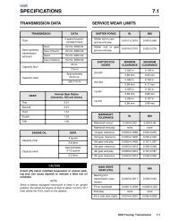
NOTE<br />
Check the eight digit number stamped on the transmission<br />
ca<strong>se</strong> just above the side door. If the third digit is “9,” then the<br />
transmission was built for Japan only. If the digit is “0,” then it<br />
was built for all countries except Japan. See the instructions<br />
which follow if <strong>se</strong>rvicing a Japane<strong>se</strong> transmission. For all<br />
other transmissions, <strong>se</strong>e Section 7.6 MAINSHAFT/COUN-<br />
TERSHAFT.<br />
<strong>Mainshaft</strong><br />
Plug<br />
DISASSEMBLY<br />
●<br />
●<br />
●<br />
NOTES<br />
Perform all steps if completely overhauling the transmission<br />
as<strong>se</strong>mbly.<br />
Perform steps 1-11 and 17-18 if replacing only the countershaft<br />
or one or more countershaft gears.<br />
Perform steps 1-5 and 12-18 if replacing only the mainshaft<br />
or one or more mainshaft gears.<br />
Figure D-2. Press Out <strong>Countershaft</strong><br />
1WARNING<br />
9411<br />
●<br />
Perform steps 1-6, 12, and 17-18 if replacing only the<br />
side door bearings.<br />
1. Position the side door as<strong>se</strong>mbly on a bench with the<br />
shafts pointing straight up, the mainshaft on the left hand<br />
side. The mainshaft is the longer of the two shafts. See<br />
Figure D-3.<br />
2. Slide off the mainshaft 2nd gear (spur).<br />
NOTE<br />
To facilitate reas<strong>se</strong>mbly, label each gear as it is removed.<br />
See Figure D-1.<br />
3. Obtain the TRANSMISSION SHAFT RETAINING RING<br />
PLIERS, Part No. J-5586.<br />
9412<br />
Always wear proper eye protection when removing retaining<br />
rings. U<strong>se</strong> the correct retaining ring pliers. Verify<br />
that the tips of the pliers are not damaged or excessively<br />
worn. Slippage may propel the ring with enough force to<br />
cau<strong>se</strong> eye injury.<br />
4. Locate retaining ring just above the mainshaft 3rd gear<br />
(spur). Move the retaining ring up approximately 3/8 inch<br />
(9.5 mm) towards the free end of the shaft. Turn side<br />
door as<strong>se</strong>mbly upside down and verify that mainshaft<br />
3rd gear is still partially engaged with countershaft 3rd<br />
gear.<br />
CAUTION<br />
Failure to move the retaining ring on the mainshaft can<br />
cau<strong>se</strong> countershaft 1st gear to contact mainshaft 3rd<br />
gear when the countershaft is pres<strong>se</strong>d out. On the other<br />
hand, if the retaining ring is moved too far, loss of<br />
engagement between mainshaft 3rd gear and countershaft<br />
3rd gear can result in hard contact between the<strong>se</strong><br />
two gears. Any hard contact can result in gear tooth<br />
damage.<br />
5. With the outboard side up, rest side door on parallel<br />
blocks under ram of arbor press. Be sure that as<strong>se</strong>mbly<br />
is flat and does not rest on dowel on inboard side.<br />
Figure D-1. Note Gear Location During Disas<strong>se</strong>mbly<br />
6. Center countershaft under ram. Install mainshaft plug<br />
into hole at end of countershaft. Slowly apply pressure<br />
until countershaft is free. See Figure D-2. Remove mainshaft<br />
plug.<br />
Appendix D D-1
HOME<br />
9413<br />
1 10<br />
11<br />
3<br />
4<br />
2<br />
6<br />
12<br />
4<br />
3<br />
4<br />
3<br />
3<br />
4<br />
8<br />
5<br />
6<br />
6<br />
7<br />
13<br />
15<br />
6<br />
3<br />
4<br />
14<br />
4<br />
3<br />
9 16<br />
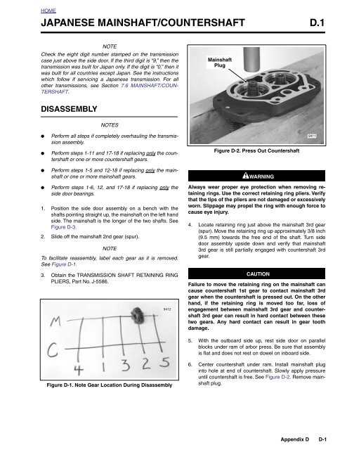
1. <strong>Mainshaft</strong><br />
2. 2nd Gear<br />
3. Retaining Ring<br />
4. Thrust Washer<br />
5. 3rd Gear<br />
6. Split Cage Bearing<br />
7. 1st Gear<br />
8. 4th Gear<br />
9. Gold Spacer<br />
10. <strong>Countershaft</strong><br />
11. 5th Gear<br />
12. 2nd Gear<br />
13. 3rd Gear<br />
14. 1st Gear<br />
15. 4th Gear<br />
16. Blue Spacer<br />
Figure D-3. Fully As<strong>se</strong>mbled Side Door<br />
7. Slide blue spacer and countershaft 4th gear (helical) off<br />
threaded end of countershaft.<br />
8. Secure countershaft in a vi<strong>se</strong> with the threaded end topside.<br />
Be sure to install a pair of aluminum or brass jaw<br />
in<strong>se</strong>rts in vi<strong>se</strong> to avoid parts damage. See Figure D-4.<br />
D-2 Appendix D
HOME<br />
9416<br />
17. Set the side door on a bench with the outboard side up.<br />
Remove retaining ring from the bearing bore.<br />
<strong>Countershaft</strong><br />
1st Gear<br />
NOTE<br />
Depending upon whether one or both shafts were removed,<br />
replace one or both side door bearings. Always replace the<br />
bearing if the shaft was pres<strong>se</strong>d out.<br />
18. Turn side door over so that the inboard side is up and<br />
place on flat plate under ram of arbor press. Apply pressure<br />
to outer race to press bearing from bore.<br />
Aluminum<br />
Jaws<br />
Figure D-4. Disas<strong>se</strong>mble/As<strong>se</strong>mble <strong>Countershaft</strong><br />
9. Remove retaining ring just above the countershaft 1st<br />
gear (spur with single row of indents on teeth). Remove<br />
thrust washer and countershaft 1st gear. Gently pull<br />
apart the split cage bearing and remove. Remove <strong>se</strong>cond<br />
thrust washer.<br />
CLEANING AND INSPECTION<br />
1. Clean all parts in cleaning solvent and blow dry with<br />
compres<strong>se</strong>d air.<br />
2. Check gear teeth for damage. Replace the gears if they<br />
are pitted, scored, rounded, cracked or chipped.<br />
3. Inspect the engaging dogs on the gears. Replace the<br />
gears if the dogs are rounded, battered or chipped.<br />
4. Inspect the side door bearings. Bearings must rotate<br />
freely without drag. Replace the bearings if pitted,<br />
grooved, or if the shafts were removed.<br />
10. Remove retaining ring above the countershaft 3rd gear<br />
(spur). Remove countershaft 3rd gear.<br />
11. Remove retaining ring just above the countershaft 2nd<br />
gear (spur). Remove thrust washer and countershaft<br />
2nd gear. Gently pull apart the split cage bearing and<br />
remove.<br />
12. Center mainshaft under ram of arbor press. Install mainshaft<br />
plug into hole at end of mainshaft. Slowly apply<br />
pressure until mainshaft is free. Remove mainshaft plug.<br />
13. Slide gold spacer, mainshaft 4th gear (helical), split cage<br />
bearing and thrust washer off end of mainshaft.<br />
14. Secure the mainshaft in a vi<strong>se</strong> with the longer splined<br />
end at the top. Be sure to install a pair of aluminum or<br />
brass jaw in<strong>se</strong>rts in vi<strong>se</strong> to avoid parts damage. See Figure<br />
D-5.<br />
15. Remove retaining ring above the mainshaft 1st gear<br />
(spur with double row of indents on teeth). Remove<br />
mainshaft 1st gear.<br />
9415<br />
<strong>Mainshaft</strong><br />
1st Gear<br />
16. Remove retaining ring just above the mainshaft 3rd gear<br />
(spur). Remove the thrust washer and mainshaft 3rd<br />
gear. Gently pull apart the split cage bearing and<br />
remove. Remove the <strong>se</strong>cond thrust washer. Remove the<br />
last retaining ring, which was moved out of the groove<br />
before the countershaft was pres<strong>se</strong>d out.<br />
Figure D-5. Disas<strong>se</strong>mble/As<strong>se</strong>mble <strong>Mainshaft</strong><br />
Appendix D D-3
HOME<br />
ASSEMBLY<br />
NOTES<br />
9417<br />
<strong>Mainshaft</strong><br />
Plug<br />
●<br />
●<br />
●<br />
●<br />
Perform all steps if the transmission as<strong>se</strong>mbly was completely<br />
overhauled.<br />
Perform steps 1-5 and 12-24 if only the countershaft or<br />
one or more countershaft gears were replaced.<br />
Perform steps 1-11 and 20-24 if only the mainshaft or<br />
one or more mainshaft gears were replaced.<br />
Perform steps 1-4, 11, and 18-24 if only the side door<br />
bearings were replaced.<br />
1. With the outboard side up, place side door on flat plate<br />
under ram of arbor press.<br />
NOTE<br />
Note the two drill points between the bearing bores on the<br />
side door. See Figure D-7. Two drill points indicate that the<br />
side door must be fitted with the new style 12mm wide bearings.<br />
Installation of the old style 14mm wide bearings would<br />
cover the retaining ring grooves.<br />
2. Position new bearing over bore with the number stamp<br />
topside.<br />
3. Applying pressure to outer race, press bearing into bore<br />
until firm contact is made with the counterbore.<br />
1WARNING<br />
Always wear proper eye protection when installing retaining<br />
rings. U<strong>se</strong> the correct retaining ring pliers. Verify<br />
that the tips of the pliers are not damaged or excessively<br />
worn. Slippage may propel the ring with enough force to<br />
cau<strong>se</strong> eye injury.<br />
4. With the flat side in towards the bearing (beveled side<br />
out), install new retaining ring in bearing bore.<br />
NOTE<br />
Depending upon the level of disas<strong>se</strong>mbly, replace one or<br />
both side door bearings. Always replace the bearing if the<br />
shaft was pres<strong>se</strong>d out.<br />
5. Obtain the TRANSMISSION SHAFT RETAINING RING<br />
PLIERS, Part No. J-5586.<br />
1WARNING<br />
Always u<strong>se</strong> new retaining rings when as<strong>se</strong>mbling the<br />
mainshaft and countershaft. Reusing retaining rings can<br />
cau<strong>se</strong> the transmission to become “locked” during<br />
motorcycle operation, a situation which could result in<br />
death or <strong>se</strong>rious injury.<br />
Figure D-6. Press In <strong>Countershaft</strong><br />
6. Secure the mainshaft in a vi<strong>se</strong> with the longer splined<br />
end at the top. Be sure to install a pair of aluminum or<br />
brass jaw in<strong>se</strong>rts in vi<strong>se</strong> to avoid parts damage.<br />
7. Install new retaining ring approximately 3/8 inch (9.5<br />
mm) below the bottom retaining ring groove.<br />
8. Slide thrust washer down mainshaft until it contacts<br />
retaining ring. Lightly coat split cage bearing with oil and<br />
install in race just above thrust washer. Install mainshaft<br />
3rd gear (spur) with the shifter dogs down. Install <strong>se</strong>cond<br />
thrust washer. Install new retaining ring in groove just<br />
above the bearing race.<br />
9. With the fork groove up, slide mainshaft 1st gear (spur<br />
with double row of indents on teeth) down mainshaft until<br />
it contacts retaining ring. Install new retaining ring in<br />
groove above the gear. See Figure D-5.<br />
CAUTION<br />
Verify that the mainshaft 1st gear has the double row of<br />
indents on teeth. Using a gear with a single row of<br />
indents will result in transmission damage.<br />
10. Slide thrust washer down the mainshaft until it contacts<br />
the retaining ring. Lightly coat the split cage bearing<br />
(double roller) with oil and install in race above the thrust<br />
washer. Install mainshaft 4th gear (helical) over the<br />
bearing with the shifter dogs down. Install gold spacer.<br />
11. With the inboard side up, place side door on flat plate<br />
under ram of arbor press. Holding mainshaft as<strong>se</strong>mbly<br />
together, remove from vi<strong>se</strong> and position over bearing<br />
bore in side door. Install mainshaft plug into hole at end<br />
of mainshaft. Supporting inner race of bearing, press<br />
mainshaft into bearing bore. Remove mainshaft plug.<br />
D-4 Appendix D
HOME<br />
<strong>Mainshaft</strong><br />
Locknut<br />
<strong>Countershaft</strong><br />
Locknut<br />
Two Drill<br />
Points<br />
9414<br />
21. Return side door as<strong>se</strong>mbly to bench. Position with the<br />
shafts pointing straight up, the mainshaft on the left hand<br />
side.<br />
22. Move partially installed retaining ring into groove just<br />
above the mainshaft 3rd gear.<br />
23. Install mainshaft 2nd gear (spur) with the fork groove<br />
down.<br />
The final as<strong>se</strong>mbly appears as shown in Figure D-3.<br />
24. Install spacer and locknut on the threaded end of each<br />
shaft and tighten the nuts until finger tight. See Figure D-<br />
7.<br />
NOTE<br />
For final tightening of the locknuts and installation of the side<br />
door, <strong>se</strong>e Section 7.6 MAINSHAFT/COUNTERSHAFT,<br />
INSTALLATION.<br />
Figure D-7. Install <strong>Mainshaft</strong>/<strong>Countershaft</strong> Locknuts<br />
12. Secure the countershaft in a vi<strong>se</strong> with the threaded end<br />
topside. Be sure to install a pair of aluminum or brass<br />
jaw in<strong>se</strong>rts in vi<strong>se</strong> to avoid parts damage.<br />
13. Lightly coat split cage bearing with oil and install in race<br />
next to the countershaft 5th gear.<br />
14. Install countershaft 2nd gear (spur) over the bearing with<br />
the shifter dogs up. Install thrust washer and new retaining<br />
ring.<br />
15. Install countershaft 3rd gear (spur) with the fork groove<br />
down. Install new retaining ring in groove above the<br />
gear.<br />
16. Slide the thrust washer down the countershaft until it<br />
contacts the retaining ring. Lightly coat the split cage<br />
bearing with oil and install in the race just above the<br />
thrust washer. Install countershaft 1st gear (spur with<br />
single row of indents on teeth) with the taper up. Install<br />
<strong>se</strong>cond thrust washer and new retaining ring. See Figure<br />
D-4.<br />
17. Install countershaft 4th gear (helical) with the sleeve<br />
down. Install blue spacer with the taper up.<br />
18. With the inboard side up, place side door on flat plate<br />
under ram of arbor press. Support inner race of bearing.<br />
19. Holding countershaft as<strong>se</strong>mbly together, remove from<br />
vi<strong>se</strong>. Raising mainshaft 3rd gear until it contacts partially<br />
installed retaining ring, position countershaft over bearing<br />
bore. Verify that taper on blue spacer is facing<br />
towards the bearing.<br />
20. Place mainshaft plug at end of countershaft. Be sure<br />
that mainshaft and countershaft gears mesh and that<br />
as<strong>se</strong>mbly is square. Press countershaft into bearing<br />
bore. Remove mainshaft plug. See Figure D-6.<br />
Appendix D D-5
HOME<br />
NOTES<br />
D-6 Appendix D