THE NAVAL ENGINEER
THE NAVAL ENGINEER
THE NAVAL ENGINEER

You also want an ePaper? Increase the reach of your titles
YUMPU automatically turns print PDFs into web optimized ePapers that Google loves.
16<br />
mean no requirement for stowage<br />
and handling of multiple reaction<br />
units, but the mechanism to install<br />
a weapon past the reaction unit<br />
would need close consideration,<br />
and the unit is likely to be larger<br />
than a disposable option, to combat<br />
the effects of multiple operations.<br />
The control and power system<br />
would also need to be capable of<br />
braking and recovering the reaction<br />
unit from within the tube, which<br />
would increase launcher length to<br />
accommodate a braking zone.<br />
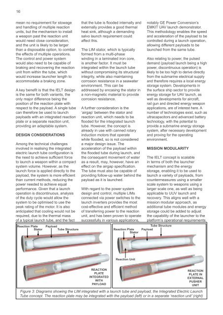
A key benefit is that the IELT design<br />
is the same for both variants, the<br />
only major difference being the<br />
position of the reaction plate with<br />
respect to the payload. A single tube<br />
can therefore be used to launch<br />
payloads with an integrated reaction<br />
plate or a separate reaction unit,<br />
providing an adaptable system.<br />
Design considerations<br />
Among the technical challenges<br />
involved in realising the integrated<br />
electric launch tube configuration is<br />
the need to achieve sufficient force<br />
to launch a weapon within a compact<br />
system volume. However, as the<br />
launch force is applied directly to the<br />
payload, the system is more efficient<br />
than current methods, reducing the<br />
power needed to achieve equal<br />
performance. Given that a launch<br />
operation is discontinuous, analysis<br />
of the duty cycle would allow the<br />
system to be optimised to use the<br />
peak rating of the motor. It is also<br />
anticipated that cooling would not be<br />
required, due to the thermal mass<br />
of a typical launch tube, and the fact<br />
Reaction Plate<br />
Stator<br />
Payload<br />
Tube Structure<br />
that the tube is flooded internally and<br />
externally provides a good thermal<br />
heat sink, although a demanding<br />
salvo launch requirement could<br />
affect this.<br />
The LIM stator, which is typically<br />
formed from a multi-phase<br />
winding in a laminated iron core,<br />
is another factor. It must be<br />
integrated within the launch tube<br />
without compromising its structural<br />
integrity, while also maintaining<br />
corrosion resistance in a seawater<br />
environment. This can be<br />
addressed by encasing the stator in<br />
a non-magnetic material to provide<br />
corrosion resistance.<br />
A further consideration is the<br />
‘airgap’ between the stator and<br />
reaction unit, which needs to be<br />
flooded for the integrated launch<br />
tube. However, the concept is<br />
already in use with canned rotary<br />
induction motors that operate<br />
while flooded, so is not considered<br />
a major design issue. The<br />
acceleration of the payload within<br />
the flooded tube during launch, and<br />
the consequent movement of water<br />
as a result, may, however, have an<br />
effect on the airgap specification.<br />
The tube must also be capable of<br />
providing follow-up water behind the<br />
payload as it is launched.<br />
With regard to the power system<br />
design and control, multiple LIMs<br />
connected via power switches to the<br />
launch inverters provides the most<br />
cost-effective and efficient method<br />
of transferring power to the reaction<br />
unit, and has been proven to operate<br />
successfully in various applications,<br />
Reaction Plate<br />
Stator<br />
notably GE Power Conversion’s<br />
EMKIT UAV launch demonstrator.<br />
This methodology enables the speed<br />
and acceleration of the payload to be<br />
controlled during a launch operation,<br />
allowing different payloads to be<br />
launched from the same tube.<br />
Also relating to power, the pulsed<br />
demand (payload launch being a high<br />
power, discontinuous operation) is<br />
likely to be too high to derive directly<br />
from the submarine electrical supply<br />
and therefore requires a local energy<br />
storage system. Developments in<br />
the surface ship sector to provide<br />
energy storage for UAV launch, as<br />
well as developments for aircraft,<br />
rail gun and directed energy weapon<br />
applications, are of interest here. A<br />
number of technologies exist, such as<br />
ultracapacitors and advanced battery<br />
technology, with the potential to<br />
provide a submarine energy storage<br />
system, after necessary development<br />
and proving for the operating<br />
environment.<br />
Mission modularity<br />
The IELT concept is scalable<br />
in terms of both the launcher<br />
mechanism and the energy<br />
storage, enabling it to be used to<br />
launch a variety of payloads, from<br />
countermeasures using a smaller<br />
scale system to weapons using a<br />
larger scale one, as well as being<br />
applicable to UUV launch and<br />
recovery. This aligns well with a<br />
mission modular approach, as<br />
additional tube modules and energy<br />
storage could be added to adjust<br />
the capability of the launcher to the<br />
platform’s operational requirements.<br />
Tube Structure<br />
Payload<br />
Reaction Unit<br />
REACTION<br />
PLATE<br />
INTEGRATED<br />
WITH<br />
PAYLOAD<br />
REACTION<br />
PLATE IN<br />
EXTERNAL<br />
PUSHER<br />
UNIT<br />
Figure 3: Diagrams showing the LIM integrated with a launch tube and payload, the Integrated Electric Launch<br />
Tube concept. The reaction plate may be integrated with the payload (left) or in a separate ‘reaction unit’ (right)