

250 - VW Phaeton W12 - Engine Management - VolksPage.Net
250 - VW Phaeton W12 - Engine Management - VolksPage.Net
250 - VW Phaeton W12 - Engine Management - VolksPage.Net

Create successful ePaper yourself
Turn your PDF publications into a flip-book with our unique Google optimized e-Paper software.
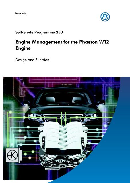
Service.<br />
Self-Study Programme <strong>250</strong><br />
<strong>Engine</strong> <strong>Management</strong> for the <strong>Phaeton</strong> <strong>W12</strong><br />
<strong>Engine</strong><br />
Design and Function
The Motronic engine management system for the<br />
<strong>W12</strong> engine allows high engine performance<br />
with low fuel consumption by adapting to all<br />
operating conditions. At the heart of the<br />
Motronic ME7.1.1 are two electronic control units.<br />
In contrast with the W8 engine, what is known as<br />
a two-control unit concept is used in the <strong>W12</strong><br />
engine. This concept regards the two cylinder<br />
banks as two separate engines. Essentially, each<br />
control unit is assigned to just one bank.<br />
Control unit 2 obtains information that has been<br />
entered only into Control unit 1 via the internal<br />
CAN databus. This internal CAN databus serves<br />
exclusively to exchange information between the<br />
engine control units.<br />
This Self-Study Programme will familiarise you<br />
with the ME7.1.1 engine management system,<br />
the interaction between the two control units, the<br />
sensors, the actuators and individual<br />
subsystems.<br />
S<strong>250</strong>_096<br />
This SSP <strong>250</strong> is based on the information in SSP 248 "The W <strong>Engine</strong> Concept“.<br />
NEW<br />
Important<br />
Note<br />
The Self-Study Programme presents the design<br />
and function of new developments.<br />
The contents are not updated.<br />
Please always refer to the relevant Service Literature<br />
for all current inspection, adjustment and repair<br />
instructions.<br />
2
Table of contents<br />
Introduction . . . . . . . . . . . . . . . . . . . . . . . . . . . . . . . . . . .4<br />
System overview . . . . . . . . . . . . . . . . . . . . . . . . . . . . . . 8<br />
Subsystems . . . . . . . . . . . . . . . . . . . . . . . . . . . . . . . . . . 12<br />
Function diagram . . . . . . . . . . . . . . . . . . . . . . . . . . . . .52<br />
Service . . . . . . . . . . . . . . . . . . . . . . . . . . . . . . . . . . . . . .58<br />
Test your knowledge . . . . . . . . . . . . . . . . . . . . . . . . . 62<br />
3
Introduction<br />
The Motronic ME7.1.1<br />
S<strong>250</strong>_225<br />
The Motronic ME7.1.1 controls the <strong>W12</strong> engine by<br />
means of two engine control units.<br />
The engine management system carries out the<br />
following tasks:<br />
Both engine control units are located in the<br />
plenum chamber on the right under the coolant<br />
expansion tank.<br />
- creates the optimum mixture for all<br />
operating conditions<br />
- reduces fuel consumption<br />
- controls combustion<br />
- checks and controls emission values<br />
4
<strong>250</strong>_033<br />
<strong>Engine</strong> control unit 1 J623<br />
<strong>Engine</strong> control unit 2 J624<br />
<strong>250</strong>_009 <strong>250</strong>_008<br />
Terminal 15 Terminal 31<br />
As both control units are completely identical<br />
and the engine control is fundamentally bankspecific,<br />
each control unit must be assigned to<br />
one of the cylinder banks. A Pin code is used to<br />
identify engine control unit 1 J623 for cylinder<br />
bank I, and engine control unit 2 J624 for<br />
cylinder bank II.<br />
Pin 49 for engine control unit 1 is linked to<br />
Terminal 15 and Pin 49 for engine control unit 2 is<br />
linked with Terminal 31. The wiring harnesses are<br />
colour-marked to distinguish them.<br />
<strong>Engine</strong> control unit 1 is also referred to as the "Master“ and engine control unit 2 as the<br />
"Slave“.<br />
5
Introduction<br />
Both engine control units manage each bank separately to ensure that the following functions run<br />
smoothly:<br />
- injection control<br />
- ignition control (ignition system with single spark ignition coils)<br />
- idling speed control<br />
- stereo lambda control of emission values<br />
- fuel tank breather system<br />
- electronic pow er control<br />
- cruise control system (CCS)<br />
- secondary air system<br />
- knock control<br />
- continually variable inlet and exhaust camshaft timing<br />
- engine mounting control<br />
- coolant temperature control<br />
- self-diagnosis<br />
The following subfunctions are assumed only by engine control unit 1:<br />
incoming sensor signals:<br />
- from the coolant temperature sender<br />
- from the accelerator position sender<br />
- from the brake light switch<br />
- from the brake pedal switch<br />
- from the CCS switch<br />
- from the kick-down switch<br />
activated actuators:<br />
- the current supply relay<br />
- the fuel pumps<br />
- the continued coolant circulation pump<br />
- the mapped-controlled engine cooling<br />
thermostat<br />
- the electro-hydraulic engine mounting<br />
solenoid valve<br />
- the radiator fan<br />
The input signals are processed by engine control unit 1 and transmitted to engine control unit 2 via the<br />
internal CAN databus.<br />
There is only one G28 engine speed sender in the system. It transmits the engine speed signal<br />
to both engine control unit 1 and engine control unit 2.<br />
6
<strong>Engine</strong> control units in the CAN databus drive<br />
<strong>Engine</strong> control units 1 and 2 communicate with<br />
the control units of other vehicle systems.<br />
Data is exchanged over the Drive Train CAN<br />
databus. It connects the individual control units<br />
to an overall system.<br />
Immobiliser<br />
<strong>Engine</strong><br />
control unit 1<br />
ABS<br />
control unit<br />
Steering angle<br />
sensor<br />
Control unit in the<br />
dash panel insert<br />
Kessy<br />
Internal CAN databus<br />
CAN-Low<br />
CAN-High<br />
<strong>Engine</strong><br />
control unit 2<br />
Gearbox<br />
control unit<br />
Airbag<br />
control unit<br />
Air conditioner<br />
control unit<br />
Onboard power<br />
supply control<br />
unit<br />
Steering column<br />
module<br />
S<strong>250</strong>_104<br />
The internal CAN databus has been added for<br />
engine management in the <strong>W12</strong> engine due to<br />
the two-control unit concept.<br />
The internal CAN databus only exchanges<br />
information between the two engine control<br />
units.<br />
Kessy = entry and start authorisation relay J 518<br />
(Kessy = Keyless Entry)<br />
7
System control<br />
<strong>Engine</strong> control unit 1<br />
Sensors<br />
G70 Air mass meter<br />
G42 Intake air temperature sender<br />
G28 <strong>Engine</strong> speed sender<br />
G62 Coolant temperature sender<br />
G83 Coolant temperature sender<br />
radiator outlet<br />
G39 Lambda probe<br />
CAN<br />
G108 Lambda probe II<br />
G130 Lambda probe after catalyst<br />
<strong>Engine</strong> control unit 1<br />
J623<br />
G131 Lambda probe II after catalyst<br />
G40 Hall sender<br />
G300Hall sender 3<br />
G61 Knock sensor I<br />
G66 Knock sensor II<br />
J338 Throttle valve control unit<br />
G187 Throttle valve drive angle sender -1-<br />
G188 Throttle valve drive angle sender -2-<br />
Accelerator pedal module with<br />
G79 Accelerator pedal position sender<br />
G185 Accelerator pedal position sender -2-<br />
Diagnosis<br />
connection<br />
Internal CAN databus<br />
F8<br />
Kick-down switch<br />
E45 CCS switch<br />
E227 CCS button<br />
<strong>Engine</strong> control unit 2<br />
J624<br />
F<br />
F47<br />
Brake light switch<br />
CCS brake pedal switch<br />
8<br />
S<strong>250</strong>_003
Actuators<br />
J17<br />
G6<br />
Fuel pump relay<br />
Fuel pump (pre-supply pump)<br />
J49 Fuel pump relay<br />
G23 Fuel pump<br />
J338 Throttle valve control unit<br />
G186 Throttle valve drive<br />
N30 Injector, cylinder 1, N31 Injector, cylinder 2<br />
N32 Injector, cylinder 3, N33 Injector, cylinder 4<br />
N83 Injector, cylinder 5, N84 Injector, cylinder 6<br />
N70 Ignition coil 1 with output stage, N127 Ignition coil 2<br />
N291 Ignition coil 3 with output stage, N292 Ignition coil 4 output<br />
stage<br />
N323 Ignition coil 5 output stage, N324 Ignition coil 6 output stage<br />
N205 Inlet camshaft timing adjustment valve -1-<br />
N318 Exhaust camshaft timing adjustment valve -1-<br />
N80 Activated charcoal filter system solenoid valve 1<br />
N112<br />
Secondary air inlet valve<br />
V101<br />
J299<br />
Secondary air pump motor<br />
Secondary air pump relay<br />
J271 Motronic current supply relay<br />
J670 Motronic current supply relay -2-<br />
J235<br />
V51<br />
Coolant pump relay<br />
Continued coolant circulation pump<br />
F265<br />
Mapped-controlled engine cooling thermostat<br />
N145 Electro-hydraulic engine mounting solenoid valve, right<br />
V7 Radiator fan<br />
V177 Radiator fan -2-<br />
9
System overview<br />
<strong>Engine</strong> control unit 2<br />
Sensors<br />
G28<br />
<strong>Engine</strong> speed sender<br />
G246 Air mass meter 2<br />
G299 Intake air temperature sender -2-<br />
<strong>Engine</strong> control unit 1<br />
J 623<br />
G285 Lambda probe III<br />
G286 Lambda probe IV<br />
G287 Lambda probe III after catalyst<br />
Diagnostic<br />
connection<br />
Internal CAN databus<br />
G288 Lambda probe IV after catalyst<br />
G163 Hall sender 2<br />
G301 Hall sender 4<br />
<strong>Engine</strong> control unit 2<br />
J 624<br />
G198 Knock sensor 3<br />
G199 Knock sensor 4<br />
CAN<br />
J544 Throttle valve control unit 2<br />
G297 Angle sender -1- for throttle valve drive 2<br />
G298 Angle sender -2- for throttle valve drive 2<br />
10
Actuators<br />
J 544 Throttle valve control unit 2<br />
G296 Throttle valve drive 2<br />
N85 Injector, cylinder 7, N86 Injector, cylinder 8<br />
N299 Injector, cylinder 9, N300 Injector, cylinder 10<br />
N301 Injector, cylinder 11, N302 Injector, cylinder 12<br />
N325 Ignition coil 7 with output stage,<br />
N326 Ignition coil 8 with output stage<br />
N327 Ignition coil 9 output stage,<br />
N328 Ignition coil 10 outputstage,<br />
N329 Ignition coil 11 output stage,<br />
N330 Ignition coil 12 outputstage<br />
N208 Inlet camshaft timing adjustment valve 2<br />
N319 Exhaust camshaft timing adjustment valve 2<br />
N333 Activated charcoal filter system solenoid valve 2<br />
N320 Secondary air inlet valve 2<br />
V189 Secondary air pump motor 2<br />
J545 Secondary air pump relay 2<br />
S<strong>250</strong>_005<br />
11
Subsystems<br />
The position of the actuators and sensors in the following diagrams of the subsystems are not<br />
identical to the physical layout in the engine compartment.<br />
Fuel injection system<br />
17<br />
16<br />
3<br />
4<br />
19<br />
5<br />
5<br />
5<br />
5<br />
5<br />
5<br />
Internal CAN databus<br />
18<br />
6<br />
6<br />
6<br />
6<br />
6<br />
6<br />
1<br />
7<br />
9<br />
2<br />
14 15<br />
13<br />
12<br />
11 8 S<strong>250</strong>_010<br />
10<br />
Bank I<br />
1 <strong>Engine</strong> control unit 1<br />
3 Fuel pump 1<br />
4 Fuel pump 2<br />
5 Injectors, Bank I<br />
7 Air mass meter 1 with<br />
intake air temperature sender<br />
9 Lambda probes, Bank I<br />
11 Throttle valve control unit 1<br />
13 Accelerator pedal module<br />
14 Temperature sender G62<br />
15 <strong>Engine</strong> speed sender<br />
16 Fuel tank<br />
17 Filter<br />
18 Fuel rail<br />
19 Fuel pressure regulator<br />
Bank II<br />
2 <strong>Engine</strong> control unit 2<br />
6 Injectors Bank II<br />
8 Air mass meter 2 with<br />
intake air temperature sender<br />
10 Lambda probes, Bank II<br />
12 Throttle valve control unit 2<br />
15 <strong>Engine</strong> speed sender<br />
12
Input signals for calculating injection time<br />
● Air mass meter engine load signals<br />
● Intake air temperatures<br />
● Throttle valve control unit signals<br />
● <strong>Engine</strong> speed sender signal<br />
● Coolant temperature<br />
● Lambda probe signals<br />
● Accelerator pedal module signal<br />
The fuel pumps located in the fuel tank convey<br />
the fuel through the fuel filter to the injectors.<br />
Fuel pump 2 is switched on additionally<br />
depending on the amount of fuel required. The<br />
injectors are interconnected by means of a fuel<br />
rail. Injection is sequential. Using the input<br />
signals, the control units calculate the required<br />
fuel quantity and the corresponding injection<br />
time for each bank.<br />
The opening time of the injector alone defines<br />
the fuel quantity injected. The pressure regulator<br />
regulates the injection pressure in the fuel rail<br />
and regulates the return of unused fuel to the<br />
fuel tank.<br />
13
Subsystems<br />
Air mass meters G70 and G246 with<br />
intake air temperature senders G42 and G299<br />
Air mass meter G70 determines the air mass and<br />
sender G42 determines the temperature of the<br />
intake air for cylinder bank I.<br />
Air mass meter G246 and sender G299<br />
determine the dimensions and temperature of<br />
the intake air for cylinder bank II.<br />
S<strong>250</strong>_035<br />
S<strong>250</strong>_097<br />
S<strong>250</strong>_039<br />
G246, G299 G70, G42<br />
S<strong>250</strong>_037<br />
Senders G246, G299<br />
for Bank II<br />
Senders G70, G42<br />
for Bank I<br />
Bank I<br />
Bank II<br />
S<strong>250</strong>_116<br />
Senders G246 and G299 for cylinder bank II are<br />
attached above cylinder bank I. Their signals are<br />
transmitted to engine control unit 2.<br />
Senders G70 and G42 for cylinder bank I are<br />
attached above cylinder bank II.<br />
Their signals are transmitted to engine control<br />
unit 1.<br />
14
The air filter, the air mass meter with intake air temperature sender, and the<br />
throttle valve positioner are attached to the opposite cylinder bank.<br />
Signal failure strategies<br />
If air mass meter G 70 or G246 fails, the air mass<br />
is calculated using the throttle valve position<br />
which then produces an alternative model. The<br />
MIL fault indicator lamp lights up.<br />
If intake air temperature sender G42 or G299<br />
fails, an alternative temperature is calculated<br />
using the air conditioning system ambient<br />
temperature sensor.<br />
<strong>Engine</strong> speed sender G28<br />
<strong>Engine</strong> speed sender G28 provides an important<br />
input signal. It is located in the gearbox housing.<br />
The sensor used is a Hall sensor.<br />
The engine speed and position of the crankshaft<br />
are detected by scanning the teeth of the<br />
converter plate with integrated sender wheel.<br />
The gap on the sender wheel acts as a reference<br />
mark for the engine control unit.<br />
Failure strategies<br />
S<strong>250</strong>_318<br />
<strong>Engine</strong> speed sender G28 is directly linked to<br />
both engine control units.<br />
This means it transmits the engine speed signal<br />
both to engine control unit 1 and engine control<br />
unit 2.<br />
Continued travel is possible if the sender<br />
fails. However, at the next attempt to restart, the<br />
engine will not start.<br />
15
Subsystems<br />
Fuel pumps G6 and G23<br />
The two chambers of the fuel tank each contain<br />
both an electric fuel pump and a suction jet<br />
pump (entrainment pump).<br />
With the aid of the pressure regulator, electric<br />
fuel pumps G6 and G23 generate a fuel system<br />
pressure of 4 bar and are activated by engine<br />
control unit 1.<br />
G23 in the pre-supply tank<br />
Main chamber<br />
G6 in the pre-supply tank<br />
Suction jet pump<br />
(entrainment pump) 1<br />
Suction jet pump<br />
(entrainment pump) 2<br />
Secondary<br />
chamber<br />
S<strong>250</strong>_007<br />
Fuel pump G23 is the main pump. It delivers a<br />
continuous supply of fuel to the engine while the<br />
engine is running. The second fuel pump G6 is<br />
additionally switched on either on starting to<br />
achieve a quicker pressure build-up, if the fuel<br />
tank has less than 20 litres or if there is a high<br />
engine load and engine speed.<br />
Suction jet pump (entrainment pump) 1 delivers<br />
the fuel from the main chamber into the presupply<br />
tank of fuel pump G6, and suction jet<br />
pump (entrainment pump) 2 pumps fuel out of<br />
the secondary chamber into the pre-supply tank<br />
of fuel pump G23.<br />
Failure strategies<br />
If one of the pumps fails, engine performance is<br />
reduced as the result of a lack of fuel.<br />
It is no longer possible to achieve top speed. At<br />
high engine speeds the engine runs unevenly.<br />
16
Injectors<br />
N30, N31, N32, N33, N83, N84,<br />
N85, N86, N299, N300, N301, N302<br />
Bank I<br />
Fuel pumps<br />
Fuel rail<br />
S<strong>250</strong>_042<br />
Bank II<br />
Fuel pressure<br />
regulator<br />
S<strong>250</strong>_041<br />
The injectors are activated by the engine control<br />
units according to the firing order.<br />
This means engine control unit 1 activates the<br />
injectors for cylinder bank I<br />
N30, N31, N32, N33, N83, N84.<br />
The injectors are directly secured to a common<br />
fuel rail with securing clips and inject the finely<br />
atomised fuel directly in front of the relevant<br />
inlet valves.<br />
<strong>Engine</strong> control unit 2 activates the injectors for<br />
cylinder bank II<br />
N85, N86, N299, N300, N301, N302 an.<br />
Failure strategies<br />
If an injector is blocked, a mixture deviation is<br />
detected by the diagnosis system.<br />
The supply of fuel is interrupted, which means<br />
the engine runs with reduced power output.<br />
A fault is recorded in the engine control unit.<br />
17
Subsystems<br />
Ignition system<br />
15<br />
15<br />
16<br />
16<br />
3<br />
5<br />
6<br />
4<br />
Internal CAN databus<br />
1<br />
2<br />
10 9<br />
7 11 12<br />
8 S<strong>250</strong>_011<br />
13 14<br />
Bank I<br />
1 <strong>Engine</strong> control unit 1<br />
3 Single spark ignition coils with output stage Bank I<br />
5 Spark plugs Bank I<br />
7 Air mass meter 1 with intake air temperature sender<br />
9 <strong>Engine</strong> speed sender<br />
10 Temperature sender G62<br />
11 Throttle valve control unit 1, Bank I<br />
13 Knock sensors 1 and 2, Bank I<br />
15 Hall senders 1 and 3, Bank I<br />
Bank II<br />
2 <strong>Engine</strong> control unit 2<br />
4 Single spark ignition coils with output stage Bank II<br />
6 Spark plugs Bank II<br />
8 Air mass meter 2 with intake air temperature sender<br />
9 <strong>Engine</strong> speed sender<br />
12 Throttle valve control unit 2, Bank II<br />
14 Knock sensors 3 and 4, Bank II<br />
16 Hall senders 2 and 4, Bank II<br />
Input signals for calculating the firing point<br />
● <strong>Engine</strong> speed sender signal<br />
● Air mass meter engine load signals<br />
● Throttle valve control unit signals<br />
● Coolant temperature<br />
● Knock sensor signals<br />
● Hall sender signals<br />
The firing point is calculated from a map stored in the engine control unit memory.<br />
The engine control unit also makes allowance for the input signals.<br />
18
Single spark ignition coils<br />
N70, N127, N291, N292, N323, N324,<br />
N325, N326, N327, N328, N329, N330<br />
S<strong>250</strong>_045<br />
S<strong>250</strong>_368<br />
The output stage and ignition coil are combined<br />
in each element of the single spark ignition coils,<br />
which means that the ignition can be influenced<br />
by the engine management individually for each<br />
cylinder.<br />
The single spark ignition coils deliver just one<br />
ignition spark via the spark plugs.<br />
Single spark ignition coils<br />
N70, N127, N291, N292, N323, N324<br />
are activated by engine control unit 1.<br />
<strong>Engine</strong> control unit 2 activates<br />
single spark ignition coils<br />
N325, N326, N327, N328, N329, N330.<br />
Failure strategies<br />
If an ignition coil fails, a mixture deviation is<br />
detected by the diagnosis system. The engine<br />
runs at reduced power and a fault is recorded in<br />
the engine control unit.<br />
19
Subsystems<br />
Knock control<br />
9<br />
9<br />
10<br />
10<br />
3<br />
5<br />
6<br />
4<br />
7<br />
8<br />
8<br />
7<br />
Internal CAN databus<br />
1<br />
2<br />
S<strong>250</strong>_012<br />
Bank I<br />
1 <strong>Engine</strong> control unit 1<br />
3 Single spark ignition coils with output stage Bank I<br />
5 Spark plugs Bank I<br />
7 Knock sensors 1 and 2, Bank I<br />
9 Hall senders 1 and 3, Bank I<br />
Bank II<br />
2 <strong>Engine</strong> control unit 2<br />
4 Single spark ignition coils with output stage Bank II<br />
6 Spark plugs Bank II<br />
8 Knock sensors 3 and 4, Bank II<br />
10 Hall senders 2 and 4, Bank II<br />
Input signals<br />
● Knock sensor signal<br />
● Hall sender signal<br />
Each bank in the <strong>W12</strong> engine has two knock<br />
sensors attached to the crankcase. The plug and<br />
socket connections are colour coded to avoid<br />
confusing the sensors with the connectors in the<br />
engine wiring harness. Knock signals are<br />
selectively assigned to individual cylinders using<br />
the Hall signals.<br />
If the knock sensors detect knocking in a cylinder,<br />
then the engine management changes the firing<br />
point of the affected cylinder (ignition advance<br />
angle adjusted towards "retard“), until knocking<br />
no longer occurs.<br />
If there is no further tendency to knocking in the<br />
cylinder concerned, then the control unit returns<br />
the ignition advance angle to its original position<br />
(adjustment towards "advance“).<br />
20
Knock sensors G61, G66, G198, G199<br />
Cylinder-selective knock control is combined with<br />
electronic control of the firing point. Each bank in<br />
the <strong>W12</strong> engine has two knock sensors attached<br />
to the crankcase.<br />
The engine control units detect the knocking<br />
cylinder by means of the knock sensors.<br />
Here, knock sensors G61 and G66 transmit the<br />
signals to engine control unit 1, and knock<br />
sensors G198 and G199 transmit to engine<br />
control unit 2. An ignition angle adjustment<br />
starts, and this continues until there is no further<br />
knocking.<br />
G198<br />
G66<br />
G199<br />
G61<br />
S<strong>250</strong>_049<br />
S<strong>250</strong>_013<br />
G61<br />
S<strong>250</strong>_051<br />
S<strong>250</strong>_053<br />
Signal failure strategies<br />
If a knock sensor fails, the ignition advance<br />
angles of the cylinder group are retarded by<br />
setting them to a safety ignition advance angle in<br />
the direction of "retard“. This can also lead to a<br />
rise in fuel consumption.<br />
If all the knock sensors fail, the engine<br />
management reverts to emergency knock control,<br />
where the ignition advance angles are generally<br />
retarded and full engine performance is no<br />
longer available.<br />
21
Subsystems<br />
Variable valve timing<br />
2<br />
Bank II<br />
10<br />
6<br />
4<br />
Internal CAN databus<br />
10<br />
7 9<br />
3<br />
5<br />
8<br />
1<br />
9<br />
Bank I<br />
11<br />
S<strong>250</strong>_014<br />
Bank I<br />
1 <strong>Engine</strong> control unit 1<br />
3 Camshaft timing adjustment valves, Bank I<br />
5 Air mass meter 1 with intake air temperature sender<br />
7 <strong>Engine</strong> speed sender<br />
8 Temperature sender G62<br />
9 Hall senders 1 and 3, Bank I<br />
11 Oil temperature<br />
Bank II<br />
2 <strong>Engine</strong> control unit 2<br />
4 Camshaft timing adjustment valves, Bank II<br />
6 Air mass meter 2 with intake air temperature sender<br />
7 <strong>Engine</strong> speed sender<br />
10 Hall senders 2 and 4, Bank II<br />
22
Input signals<br />
● Hall sender signal<br />
● <strong>Engine</strong> speed sender signal<br />
● Air mass meter engine load signals<br />
● Coolant temperature<br />
● Oil temperature<br />
To carry out variable valve timing, the engine<br />
control units require information about engine<br />
speed, engine load, engine temperature, the<br />
position of the crankshaft and camshaft, plus the<br />
oil temperature from the dash panel insert via<br />
the Drive Train CAN databus.<br />
The vane-cell adjusters turn and adjust the<br />
camshafts in accordance with defaults in the<br />
engine control unit.<br />
The camshafts are adjusted according to maps<br />
stored in the control units. Both the inlet and<br />
exhaust camshafts are continuously adjustable.<br />
Depending on the operating state, engine control<br />
unit 1 activates the electromagnetic valves for<br />
Bank I and engine control unit 2 activates the<br />
valves for Bank II. <strong>Engine</strong> oil travels to the vanecell<br />
adjusters via oil galleries in the central<br />
housing.<br />
If the fault memory is erased, then the adaption of the camshafts is also erased.<br />
This then requires camshaft timing adaption.<br />
If there is no adaption, camshaft timing is unadjusted, resulting in a noticeably reduced<br />
performance.<br />
23
Subsystems<br />
Hall senders G40, G163, G300, G301<br />
The Hall senders are all located in the engine<br />
timing chain cover.<br />
Their task is to inform the engine control unit of<br />
the position of the inlet and exhaust camshafts.<br />
They therefore scan a quick-start sender wheel<br />
located on the camshaft in question.<br />
S<strong>250</strong>_203<br />
Exhaust port II<br />
G301<br />
Inlet port II<br />
G163<br />
Inlet port I<br />
G40<br />
Exhaust port I<br />
G300<br />
<strong>Engine</strong> control unit 1 detects the position of the<br />
inlet camshaft by means of Hall sender G40, and<br />
by means of G300 it detects the position of<br />
exhaust camshaft in Bank I. <strong>Engine</strong> control unit 2<br />
detects the position of inlet camshaft by means of<br />
Hall sender G163, and by means of G301 it<br />
detects the position of exhaust camshaft in Bank<br />
II.<br />
The Hall sender signals act as input signals for<br />
variable valve timing.<br />
To calculate injection time and firing point, the<br />
signal from sender G40 in engine control unit 1<br />
and the signal from sender G163 in engine<br />
control unit 2 are processed.<br />
Signal failure strategies<br />
A sender failure will prevent variable valve<br />
timing in the associated bank.<br />
The camshafts are positioned at their reference<br />
positions (emergency running position). The<br />
engine runs with reduced torque.<br />
24
Inlet camshaft timing adjustment valve 1 N205 and valve 2 N208 and<br />
exhaust camshaft timing adjustment valve 1 N318 and valve 2 N319.<br />
The electromagnetic valves are integrated in the<br />
variable valve timing central housing. Based on<br />
defaults from engine control unit 1 for Bank I or<br />
from engine control unit 2 for Bank II, they<br />
distribute oil pressure depending on the<br />
adjustment direction and the adjustment<br />
distance to the camshaft adjusters.<br />
The inlet camshafts are continuously adjustable<br />
within a range of 52û. Similarly, the exhaust<br />
camshaft can be continuously adjusted within a<br />
range of 22û.<br />
Valves N205 and N318 for continuous inlet and<br />
exhaust camshaft timing adjustment in Bank I are<br />
activated by engine control unit 1. Valves N208<br />
and N319 for inlet and exhaust camshaft timing<br />
adjustment in Bank II are activated by engine<br />
control unit 2.<br />
Inlet camshaft<br />
vane cell adjuster<br />
N205<br />
N318<br />
N208<br />
N319<br />
Exhaust camshaft<br />
vane cell adjuster<br />
Bank I<br />
Bank II<br />
S<strong>250</strong>_015<br />
S<strong>250</strong>_328<br />
Central housing<br />
Vane cell adjuster<br />
Exhaust camshaft<br />
Vane cell adjuster<br />
Inlet camshaft<br />
Central housing<br />
Signal failure strategies<br />
If an electrical lead to the camshaft adjusters is<br />
faulty or a camshaft adjuster fails because it has<br />
jammed mechanically or oil pressure is too low,<br />
no camshaft timing adjustment is made.<br />
The shaft concerned is moved to the reference<br />
position in the direction of "retard“. The engine<br />
has neither full power nor high torque.<br />
25
Subsystems<br />
Stereo lambda control<br />
5<br />
1<br />
15<br />
16 17<br />
18<br />
6<br />
1<br />
2<br />
Internal CAN databus<br />
13<br />
14<br />
9<br />
10<br />
12<br />
11<br />
7<br />
8<br />
3<br />
4<br />
S<strong>250</strong>_016<br />
Bank I<br />
1 <strong>Engine</strong> control unit 1<br />
3 Injectors Bank I<br />
5 Air mass meter 1 with intake air temperature sender<br />
7 Lambda probe 1, before catalyst Bank I<br />
9 Lambda probe 2, before catalyst Bank I<br />
11 Lambda probe 1, after catalyst Bank I<br />
13 Lambda probe 2, after catalyst Bank I<br />
15 Temperature sender G62<br />
16 Throttle valve control unit 1, Bank I<br />
18 <strong>Engine</strong> speed sender<br />
Bank II<br />
2 <strong>Engine</strong> control unit 2<br />
4 Injectors Bank II<br />
6 Air mass meter 2 with Intake air temperature sender<br />
8 Lambda probe 1, before catalyst, Bank II<br />
10 Lambda probe 2, before catalyst, Bank II<br />
12 Lambda probe 1, after catalyst, Bank II<br />
14 Lambda probe 2, after catalyst, Bank II<br />
17 Throttle valve control unit 2, Bank II<br />
18 <strong>Engine</strong> speed sender<br />
26
Input signals<br />
● <strong>Engine</strong> speed sender signal<br />
● Air mass meter engine load signals<br />
● Lambda probe signals<br />
● Coolant temperature<br />
● Throttle valve control unit signal<br />
In stereo lambda control the correct composition<br />
of the fuel/air mixture for the two cylinder banks<br />
is achieved via separate closed control loops. For<br />
each cylinder head the <strong>W12</strong> engine has two<br />
exhaust manifolds.<br />
Each of these exhaust manifolds has a lambda<br />
probe upstream and downstream of the catalyst.<br />
The total of eight lambda probes inform the<br />
control unit about how much oxygen remains in<br />
the exhaust gas.<br />
Using this signal, the control unit calculates the<br />
present mixture composition. If there are<br />
deviations from the nominal value, the injection<br />
time is adjusted.<br />
In addition, an adaptive lambda control is<br />
carried out in idling mode as well as in two<br />
part-throttle ranges. This means that the<br />
control unit adjusts to the operating states and<br />
stores the learned values.<br />
27
Subsystems<br />
Lambda probes<br />
Broad-band lambda probes<br />
G39, G108, G285, G286<br />
Planar lambda probe<br />
A broad-band lambda probe is assigned to each<br />
pre-catalyst as a lambda probe upstream of the<br />
catalyst.<br />
The lambda value is determined by means of<br />
linear increase in current intensity, making it<br />
possible to measure across the entire rev range.<br />
S<strong>250</strong>_124<br />
Signal utilisation<br />
The lambda probe upstream of the catalyst<br />
supplies the signal for the mixture preparation.<br />
Lambda probes G39, G108, G130 and G131<br />
transmit the signals to engine control unit 1.<br />
G131<br />
Pre-catalyst<br />
G108<br />
G130<br />
Signal failure strategies<br />
Pre-catalyst<br />
If the lambda probe upstream of the catalyst fails<br />
there is no lambda control. Adaption is inhibited.<br />
A map-based open control loop<br />
takes over emergency operation.<br />
G39<br />
Broad-band lambda probe<br />
S<strong>250</strong>_122<br />
28
Planar lambda probe<br />
Planar lambda probes<br />
G130, G131, G287 and G288<br />
S<strong>250</strong>_124<br />
The planar lambda probe is located downstream<br />
of the pre-catalyst. Because of its two-state<br />
measurement range it may also be called a twostate<br />
lambda probe. It monitors the downstream<br />
of the catalyst around the value lambda=1.<br />
Signal utilisation<br />
G288<br />
Pre-catalyst<br />
The lambda probe downstream of the catalyst<br />
tests the function of the catalyst and the lambda<br />
closed control loop.<br />
Lambda probes G285, G286, G287 and G288<br />
transmit signals to engine control unit II.<br />
G286<br />
G287<br />
Pre-catalyst<br />
G285<br />
Signal failure strategies<br />
If the lambda probe assigned to the post-catalyst<br />
fails, lambda control continues to function. The<br />
function of the catalyst cannot be verified.<br />
S<strong>250</strong>_348<br />
Broad-band lambda probe<br />
S<strong>250</strong>_122<br />
29
Subsystems<br />
Fuel tank breather system<br />
6<br />
5<br />
4<br />
3<br />
Internal CAN databus<br />
1 2<br />
13 14<br />
7<br />
9<br />
11 12<br />
10<br />
8<br />
<strong>250</strong>_103<br />
Bank I<br />
1 <strong>Engine</strong> control unit 1<br />
3 Fuel tank<br />
4 Activated charcoal canister<br />
5 Activated charcoal filter system solenoid valve 1, Bank I<br />
7 Air mass meter 1 with intake air temperature sender<br />
9 Lambda probes, Bank I<br />
11 Throttle valve control unit 1, Bank I<br />
13 Temperature sender G62<br />
14 <strong>Engine</strong> speed sender<br />
Bank II<br />
2 <strong>Engine</strong> control unit 2<br />
6 Activated charcoal filter system solenoid valve 2, Bank II<br />
8 Air mass meter 2 with intake air temperature sender<br />
10 Lambda probes Bank II<br />
12 Throttle valve control unit 2, Bank II<br />
14 <strong>Engine</strong> speed sender<br />
30
Input signals for controlling the fuel tank breather system<br />
● <strong>Engine</strong> speed<br />
● Air mass meter engine load signals<br />
● <strong>Engine</strong> temperature<br />
● Lambda probe signal<br />
● Signal from the throttle valve control unit<br />
The fuel tank breather system prevents fuel<br />
vapour originating in the fuel tank from escaping<br />
to the atmosphere.<br />
Fuel vapour is stored in the activated charcoal<br />
canister. After evaluating the incoming signals,<br />
engine control unit 1 activates solenoid valve 1 for<br />
Bank I while engine control unit 2 activates<br />
solenoid valve 2 for Bank II.<br />
The fuel vapour stored in the activated charcoal<br />
canister is fed to the engine via the intake<br />
manifold and is combusted. This causes a<br />
temporary change in the fuel/air mixture.<br />
This change in the mixture is detected by the<br />
lambda probes, causing the lambda probe<br />
control to make a corrective adjustment.<br />
31
Subsystems<br />
The activated charcoal filter system solenoid valves N80 and N115<br />
S<strong>250</strong>_332<br />
Fitting location for N80<br />
Fitting location for N115<br />
The activated charcoal filter system solenoid<br />
valves are located directly in the direction of<br />
travel behind the intake manifold.<br />
Signal failure strategies<br />
to the intake<br />
manifold<br />
S<strong>250</strong>_334<br />
from the activated<br />
charcoal canister<br />
If there is a power interruption, the solenoid<br />
valves remain closed. The fuel tank is not vented.<br />
32
Activated charcoal canister<br />
S<strong>250</strong>_364<br />
S<strong>250</strong>_346<br />
The activated charcoal canister is located below<br />
the vehicle in the spare-wheel well.<br />
The spare-wheel well is closed off by a<br />
plastic cover to protect it against soiling.<br />
The activated charcoal canister absorbs fuel<br />
vapours. The stored fuel vapour is fed in pulses<br />
to the engine via the intake manifold.<br />
33
Subsystems<br />
Cruise control system (CCS)<br />
without automatic distance control (ADC)<br />
The cruise control system can be activated from a road speed of 30 kph.<br />
6<br />
5<br />
Internal CAN databus<br />
1<br />
2<br />
3<br />
4<br />
8<br />
7<br />
S<strong>250</strong>_018<br />
Bank I<br />
1 <strong>Engine</strong> control unit 1<br />
3 Throttle valve control unit 1, Bank I<br />
5 <strong>Engine</strong> speed sender<br />
6 Brake pedal switch<br />
7 CCS sw itch<br />
8 Road speed signal from ABS control unit J104<br />
Bank II<br />
2 <strong>Engine</strong> control unit 2<br />
4 Throttle valve control unit 2, Bank II<br />
5 <strong>Engine</strong> speed sender<br />
CCS with ADC<br />
For more detailed information about the CCS with APC please refer to SSP 276 "Automatic<br />
Distance Control ADC“.<br />
34
Input signals<br />
● <strong>Engine</strong> speed sender signal<br />
● Throttle valve control unit signals<br />
● Road speed<br />
● "Brake actuated“ signal<br />
● On and off signal from the CCS switch<br />
The signal from the CCS switch is sent to engine<br />
control unit 1. <strong>Engine</strong> control unit 1 directs the<br />
relevant information via the internal CAN<br />
databus to engine control unit 2. The throttle<br />
valve positioners open the throttle valves<br />
depending on the road speed.<br />
Throttle valve positioner 1 is activated by engine<br />
control unit 1 and throttle valve positioner 2 is<br />
activated by engine control unit 2.<br />
When the "Brake actuated“ signal is received,<br />
the cruise control system is switched off.<br />
CCS switch<br />
The cruise control system can be actuated on the left-hand side of the multifunctional steering wheel.<br />
"CCS +“ button<br />
Increases the set speed (without touching<br />
the accelerator pedal)<br />
"SET“ button<br />
Stores the required<br />
speed<br />
- Actuation when the desired<br />
speed has been reached.<br />
- Remove foot from the<br />
accelerator pedal<br />
- the speed is kept constant.<br />
"RES“ button<br />
Resumes the previously stored speed<br />
S<strong>250</strong>_101<br />
"CCS -“ button<br />
Reduces the set speed<br />
(without touching the accelerator<br />
pedal)<br />
"CANCEL“ button<br />
Cancels selected speed<br />
"On/Off“ button<br />
S<strong>250</strong>_100<br />
35
Subsystems<br />
Throttle valve control units J338 and J544<br />
Throttle valve control unit<br />
J544 for Bank II<br />
Throttle valve control unit<br />
J338 for Bank I<br />
Throttle valve housing<br />
Throttle valve drive<br />
S<strong>250</strong>_038<br />
Bank I<br />
Bank II<br />
S<strong>250</strong>_116<br />
Throttle valve<br />
Throttle valve drive angle<br />
senders 1+2<br />
S<strong>250</strong>_105<br />
G297<br />
G298<br />
G296<br />
J544<br />
J338<br />
S<strong>250</strong>_107<br />
G187<br />
G188<br />
G186<br />
Bank I<br />
Bank II<br />
Angle senders G297 and G298 of throttle valve<br />
control unit J544 transmit the current position of<br />
the throttle valve engine control unit 2. <strong>Engine</strong><br />
control unit 2 activates the electric motor for<br />
throttle valve drive G296 to open or close the<br />
throttle valve as well as to adjust a determined<br />
throttle valve position.<br />
Angle senders G187 and G188 of throttle valve<br />
control unit J338 transmit their signals to engine<br />
control unit 1. Throttle valve drive G186 is<br />
activated by engine control unit 1.<br />
Signal failure strategies<br />
If a potentiometer fails, the throttle valve goes to<br />
emergency operation. The speed is limited to<br />
120 kph.<br />
If both potentiometers fail, the bank containing<br />
the faulty throttle valve is switched off at an<br />
engine speed of 1200 rpm. The EPC lamp lights<br />
up. It is still possible to achieve a speed of up to<br />
120 kph.<br />
36
Brake light switch F and brake pedal switch F47<br />
The brake light switch and the brake pedal switch are part of one component located in the<br />
foot controls.<br />
S<strong>250</strong>_223<br />
Signal utilisation:<br />
Both switches deliver the "Brake actuated" signal<br />
to engine control unit 1. This leads to the cruise<br />
control system being switched off.<br />
Failure strategies<br />
If a sensor fails, CCS operation is no longer<br />
possible.<br />
37
Subsystems<br />
Electronic accelerator<br />
5<br />
Auxiliary signals<br />
● Cruise control system<br />
● Air conditioning system<br />
● Lambda control<br />
● Automatic gearbox<br />
● ABS/ESP<br />
● Steering angle sensor<br />
Internal CAN databus<br />
1<br />
2<br />
3<br />
4<br />
6 7<br />
8<br />
Bank I<br />
1 <strong>Engine</strong> control unit 1<br />
3 Throttle valve control unit 1, Bank I<br />
5 Accelerator pedal module<br />
6 Electronic power control fault lamp<br />
7 Ignition, fuel injection, Bank I<br />
Bank II<br />
2 <strong>Engine</strong> control unit 2<br />
4 Throttle valve control unit 2, Bank II<br />
8 Ignition, fuel injection, Bank II<br />
S<strong>250</strong>_106<br />
Input signals<br />
● Signal from the accelerator pedal module<br />
● Auxiliary signals<br />
The driver input and the signals from the<br />
accelerator pedal module are sent to engine<br />
control unit 1. <strong>Engine</strong> control unit 1 calculates the<br />
optimum implementation of the torque<br />
requirements, making allowance for all auxiliary<br />
signals, and transfers the data to engine control<br />
unit 2.<br />
Implementation for each bank is by means of the<br />
servo-adjustable throttle valve, the ignition and<br />
the fuel injection.<br />
The electronic power control warning lamp<br />
shows the driver that there is a fault in the<br />
electric throttle operation system.<br />
38
Accelerator pedal module<br />
The accelerator pedal module is located in the<br />
foot controls. The accelerator pedal module<br />
comprises:<br />
● the accelerator pedal<br />
● accelerator pedal position sender 1, G79 and<br />
● accelerator pedal position sender 2, G185<br />
Both senders are sliding potentiometers, secured<br />
to a common shaft.<br />
Each time the accelerator pedal position is<br />
changed, the resistances of the sliding<br />
potentiometers also change, as well as the<br />
voltages transmitted to the engine control unit.<br />
The engine control unit recognises the current<br />
position of the accelerator pedal by means of the<br />
signals from both accelerator position senders.<br />
S<strong>250</strong>_233<br />
Sender<br />
S<strong>250</strong>_034<br />
Signal failure strategies<br />
If a sender fails, the system initially goes to idling mode. If the second sender is detected within a defined<br />
period, driving mode is re-enabled. If both senders fail, the engine only runs at increased idling speed<br />
and no longer reacts to the accelerator pedal.<br />
Kick-down switch F8<br />
Signal failure strategies<br />
S<strong>250</strong>_330<br />
Once the accelerator pedal has been depressed<br />
as far as the kick-down switch, the full throttle<br />
position has been reached. If the accelerator<br />
pedal is further depressed, a spring in the kickdown<br />
switch is overcome and a switching contact<br />
closed.<br />
This switch signal, along with the accelerator<br />
position sender, helps the engine control unit to<br />
detect the kick-down position.<br />
In the event of failure, the values of the<br />
accelerator position sender are used.<br />
39
Subsystems<br />
Secondary air system<br />
13<br />
15<br />
16<br />
14<br />
Internal CAN databus<br />
3<br />
7<br />
8<br />
4<br />
1<br />
9 10<br />
5 6<br />
2<br />
21<br />
11<br />
17<br />
19<br />
12<br />
23<br />
22<br />
18<br />
20<br />
24<br />
11<br />
12<br />
S<strong>250</strong>_108<br />
Bank I<br />
1 <strong>Engine</strong> control unit 1<br />
3 Secondary air pump relay 1, Bank I<br />
5 Secondary air pump 1, Bank I<br />
7 Secondary air inlet valve 1, Bank I<br />
9 Combi valve 1, Bank I<br />
11 Pre-catalyst Bank I<br />
13 Air mass meter 1 with<br />
intake air temperature sender<br />
15 Temperature sender G62<br />
16 <strong>Engine</strong> speed sender<br />
17 Lambda probe 1, before catalyst, Bank I<br />
18 Lambda probe 2, before catalyst, Bank I<br />
21 Lambda probe 1, after catalyst, Bank I<br />
22 Lambda probe 2, after catalyst, Bank I<br />
Bank II<br />
2 <strong>Engine</strong> control unit 2<br />
4 Secondary air pump relay 2, Bank II<br />
6 Secondary air pump 2, Bank II<br />
8 Secondary air inlet valve 2, Bank II<br />
10 Combi valve 2, Bank II<br />
12 Pre-catalyst Bank II<br />
14 Air mass meter 2 with<br />
intake air temperature sender<br />
16 <strong>Engine</strong> speed sender<br />
19 Lambda probe 1, before catalyst, Bank II<br />
20 Lambda probe 2, before catalyst, Bank II<br />
23 Lambda probe 1, after catalyst, Bank II<br />
24 Lambda probe 2, after catalyst, Bank II<br />
40
Input signals<br />
● Signal from the lambda probes (lambda probes before catalyst for system diagnosis only)<br />
● Coolant temperature<br />
● Air mass meter engine load signals<br />
The secondary air system reduces<br />
exhaust emissions in the cold starting phase.<br />
During a cold start there is an increased<br />
percentage of unburned hydrocarbons.<br />
The catalyst cannot process this quantity as it has<br />
not yet reached its operating temperature and a<br />
mixture must be present from lambda 1.<br />
The level of oxygen in the exhaust gases is<br />
enriched by injecting air behind the exhaust<br />
valves. This causes afterburning. The heat this<br />
releases brings the catalyst to its operating<br />
temperature more quickly.<br />
The input signals are sent to both engine control<br />
unit 1 and engine control unit 2.<br />
For each bank the secondary air pumps are then<br />
activated via secondary air relays, and parallel<br />
to this the secondary air inlet valves are also<br />
activated.<br />
The combi valves are actuated via the secondary<br />
air inlet valves by means of a vacuum. The<br />
secondary air pumps temporarily push air<br />
behind the exhaust valves into the exhaust gas<br />
flow.<br />
41
Subsystems<br />
Secondary air inlet valves N112 and N320<br />
Bank I<br />
Bank II<br />
S<strong>250</strong>_126<br />
N112<br />
S<strong>250</strong>_370<br />
N320<br />
S<strong>250</strong>_336<br />
Secondary air inlet valves N112 and N320 are<br />
two 3/2-way solenoid valves and are switched<br />
by the engine control units. They activate the<br />
combi valves via a vacuum line.<br />
Failure strategies<br />
If the control unit signal fails, the combi valve can<br />
no longer be opened. The secondary air pump is<br />
unable to inject air.<br />
Combi valves<br />
As a result of the vacuum from the secondary air inlet valve, the air route opens from the secondary air<br />
pump to the cylinder head secondary air duct. At the same time, the valve prevents hot exhaust gases<br />
from reaching the secondary air pump.<br />
Bank I<br />
Bank II<br />
S<strong>250</strong>_055<br />
S<strong>250</strong>_326<br />
42
Secondary air pumps V101 and V189<br />
Intake hose<br />
V101 for Bank I<br />
S<strong>250</strong>_052<br />
Air filter<br />
V189 for Bank II<br />
S<strong>250</strong>_117<br />
S<strong>250</strong>_119<br />
The secondary air pumps pump air and therefore<br />
oxygen via the secondary air system behind the<br />
exhaust valves. This contributes to pollution<br />
control in the engine warm-up period.<br />
Failure strategies<br />
If the power supply is interrupted, no air is<br />
pumped.<br />
Air filter<br />
open air filter<br />
closed air filter<br />
An air filter is attached to the entrance of the<br />
intake hose. There is a ball in the air filter, which<br />
closes the opening to the suction jet pump<br />
(entrainment pump) when the vehicle travels<br />
through puddles (snorkel effect).<br />
S<strong>250</strong>_372<br />
43
Subsystems<br />
<strong>Engine</strong> mounting control<br />
Input signals<br />
● <strong>Engine</strong> speed sender signal<br />
● Road speed<br />
6<br />
5<br />
Internal CAN databus<br />
1 2<br />
3<br />
4 4<br />
S<strong>250</strong>_110<br />
Bank I<br />
1 <strong>Engine</strong> control unit 1<br />
3 Electro-hydraulic engine mounting solenoid valve<br />
4 <strong>Engine</strong> mounting<br />
5 <strong>Engine</strong> speed sender<br />
6Road speed<br />
Bank II<br />
2 <strong>Engine</strong> control unit 2<br />
5 <strong>Engine</strong> speed sender<br />
The hydraulically damped engine mountings with<br />
electrical activation prevent engine vibrations<br />
from being transmitted to the body across the<br />
entire rev range.<br />
The engine control unit controls the solenoid<br />
valves depending on the engine speed and the<br />
road speed.<br />
44
<strong>Engine</strong> mounting<br />
Two hydraulically damped engine mountings ensure a high degree of driving comfort. They reduce the<br />
transmission of engine vibration to the body.<br />
Left engine support<br />
Screening cover<br />
Bearing cap<br />
S<strong>250</strong>_095<br />
Vacuum connection<br />
Right engine top<br />
Right engine<br />
mounting<br />
Right engine support<br />
Front cross-member<br />
S<strong>250</strong>_111<br />
Left engine<br />
mountings<br />
Left engine<br />
stop<br />
Electro-hydraulic engine mounting solenoid valve N145<br />
S<strong>250</strong>_316<br />
S<strong>250</strong>_338<br />
For explanations on how the engine mounting functions, please refer to SSP 249 "<strong>Engine</strong><br />
management for the Passat W8 engine“.<br />
45
Subsystems<br />
Coolant temperature control<br />
7<br />
10<br />
11<br />
9<br />
8<br />
Internal CAN databus<br />
1<br />
2<br />
13 3 4<br />
12<br />
5 6<br />
S<strong>250</strong>_112<br />
Bank I<br />
1 <strong>Engine</strong> control unit 1<br />
3 Mapped-controlled engine cooling thermostat<br />
4 Radiator fan<br />
5 Radiator fan -2-<br />
6 Water pump<br />
7 Air mass meter 1 with intake air temperature sender<br />
9 <strong>Engine</strong> speed sender<br />
10 Temperature sender G62<br />
11 Temperature sender G83<br />
12 Road speed signal from ABS control unit J104<br />
13 Oil temperature<br />
Bank II<br />
2 <strong>Engine</strong> control unit 2<br />
8 Air mass meter 2 with intake air temperature sender<br />
9 <strong>Engine</strong> speed sender<br />
46
The coolant temperature control allows the coolant temperature to be adjusted to suit the<br />
engine operating state.<br />
Input signals<br />
● <strong>Engine</strong> speed<br />
● Air mass meter engine load signals<br />
● Coolant temperature - engine outlet<br />
● Coolant temperature - radiator outlet<br />
● Road speed<br />
● Oil temperature<br />
The coolant temperature is regulated steplessly.<br />
If a large cooling capacity proves necessary after<br />
the input signals are processed, the thermostat is<br />
activated by engine control unit 1 by means of<br />
maps.<br />
At this point the large cooling circuit opens. To<br />
increase cooling capacity, engine control unit 1<br />
activates the two mapped-controlled radiator<br />
fans.<br />
47
Subsystems<br />
Coolant temperature senders G62 and G83<br />
Sender G62<br />
on the coolant outlet pipe on the engine (rear)<br />
Sender G83<br />
on the radiator outlet<br />
S<strong>250</strong>_121<br />
S<strong>250</strong>_356<br />
The actual values for the coolant temperature<br />
are measured at two different points in the<br />
cooling circuit. Sender G62 is located on the<br />
coolant outlet pipe on the engine and Sender<br />
G83 is on the radiator outlet.<br />
Both senders transmit their signals to engine<br />
control unit 1 only.<br />
<strong>Engine</strong> control unit 2 receives the necessary<br />
information via the internal CAN databus from<br />
engine control unit 1.<br />
Signal failure strategies<br />
An engine temperature model is calculated from<br />
the figures for the engine load, engine speed,<br />
intake temperature on starting the engine plus<br />
the time after starting the engine. While the<br />
engine is running, this model is constantly<br />
compared with the temperature signal from<br />
sender G62.<br />
If the measured temperature from sender G62<br />
falls below the calculated model temperature, it<br />
is assumed that sender G62 is transmitting a fault<br />
signal and calculations continue using the model<br />
temperature as a back-up temperature.<br />
48
Continued coolant circulation pump V51<br />
S<strong>250</strong>_342<br />
S<strong>250</strong>_340<br />
Continued coolant circulation pump V51 is an<br />
electrically driven pump, located in the large<br />
cooling circuit. It carries out two tasks in the<br />
cooling circuit:<br />
1. Continued coolant circulation pump V51<br />
supports the mechanically driven coolant<br />
pump at low engine speeds.<br />
This guarantees adequate coolant circulation<br />
even during "stop and go“ trips.<br />
Coolant pump V51 is switched on if required<br />
after the engine speed and coolant<br />
temperature input signals have been<br />
mapped-controlled and evaluated. It is<br />
activated by engine<br />
control unit 1.<br />
2. Continued coolant circulation pump V51<br />
ensures the circulation of coolant during<br />
coolant pump run-on. Depending on<br />
the coolant temperatures at the radiator and<br />
engine outlets, the engine oil temperature as<br />
well as the intake air temperature, after the<br />
engine is turned off it is map-controlled by<br />
engine control unit 1.<br />
If constant short trips are made, the switch-on<br />
temperature for the continued coolant circulation<br />
pump V51 is not reached, and the continued<br />
coolant circulation pump must not be allowed to<br />
seize. For this reason, it is activated for<br />
approximately 5 seconds each time the engine is<br />
started.<br />
Signal failure strategies<br />
The self-diagnosis system does not detect<br />
whether continued coolant circulation pump V51<br />
is blocked.<br />
49
Subsystems<br />
Mapped-controlled engine cooling thermostat F265<br />
S<strong>250</strong>_123<br />
Heat resistance<br />
Wax element<br />
S<strong>250</strong>_059<br />
Piston pin<br />
The thermostat is inserted from above into the<br />
upper part of the crankcase. The thermostat<br />
switches over from the small to the large cooling<br />
circuit.<br />
Maps are stored in the engine control unit and<br />
they are used to activate the thermostat. The<br />
required temperature can be reached depending<br />
on the engine operation requirements.<br />
Failure strategies<br />
It is not possible to open the large cooling circuit.<br />
The radiator fan must provide the cooling<br />
capacity.<br />
50
Radiator fans V7 and V177<br />
Output stage V7<br />
Radiator fan V7<br />
S<strong>250</strong>_344<br />
Radiator fan -2- V177<br />
Output stage V177<br />
Radiator fans V7 and V177 are attached to the<br />
front end behind the capacitor for the air<br />
conditioning system and the cooler.<br />
The fans are activated as required by a map<br />
integrated in the engine control unit.<br />
The fan controllers are accommodated in the<br />
output stages.<br />
This means that, based on the signals from the<br />
engine control unit, the fans can also be<br />
operated individually and at different engine<br />
speeds.<br />
Failure strategies<br />
If a fan fails, the indicator lamp is activated and<br />
it is not possible to travel any further.<br />
This also applies if both fans fail.<br />
51
Function diagram<br />
Terminal 30<br />
Terminal 30 SV<br />
Terminal 15 SV<br />
S<br />
e<br />
d<br />
c<br />
J271<br />
J670<br />
Brake<br />
lights<br />
b<br />
a<br />
S<br />
S<br />
S<br />
S<br />
E227<br />
E221<br />
S<br />
S<br />
F47<br />
F<br />
J527<br />
J428<br />
N30<br />
N31<br />
N32 N33 N83 N84<br />
J623<br />
N 70 N127 N291 N292 N323 N324<br />
F8<br />
G83<br />
Terminal 31<br />
z<br />
S<strong>250</strong>_302<br />
E221- Operating unit in the steering wheel<br />
E227- CCS button<br />
F - Brake light switch<br />
F47- CCS brake pedal switch<br />
F8 - Kick-down switch<br />
G83- Coolant temperature sender - radiator outlet<br />
J623- <strong>Engine</strong> control unit 1<br />
J271 - Motronic current supply relay<br />
J428- Distance control unit<br />
J527- Steering column electronics control unit<br />
J670 - Motronic current supply relay -2-<br />
N30- Injector, cylinder 1<br />
N31- Injector, cylinder 2<br />
N32- Injector, cylinder 3<br />
N33- Injector, cylinder 4<br />
N83- Injector, cylinder 5<br />
N84- Injector, cylinder 6<br />
N70- Ignition coil 1<br />
N127- Ignition coil 2<br />
N291- Ignition coil 3<br />
N292- Ignition coil 4<br />
N323- Ignition coil 5<br />
N324- Ignition coil 6<br />
P - Spark plug socket<br />
Q - Spark plugs<br />
S - Fuse<br />
52
Terminal 30<br />
e<br />
d<br />
c<br />
Terminal 30 SV<br />
Terminal 15 SV<br />
g<br />
e<br />
d<br />
c<br />
b<br />
a<br />
S<br />
b<br />
a<br />
f<br />
S<br />
N80 N112 G70<br />
G42<br />
G39 G130 G108 G131<br />
J623<br />
G79<br />
G185<br />
G187 G188 G186<br />
J338<br />
G61<br />
G66<br />
Terminal 31<br />
z<br />
G42 - Intake air temperature sender<br />
G61 - Knock sensor I<br />
G66 - Knock sensor II<br />
G70 - Air mass meter<br />
G39 - Lambda probe<br />
G108 - Lambda probe II<br />
G130 - Lambda probe after catalyst<br />
G131 - Lambda probe II after catalyst<br />
G79 - Accelerator position sender<br />
G185 - Accelerator pedal position sender -2-<br />
J338 - Throttle valve control unit<br />
G186 - Throttle valve drive<br />
G187 - Throttle valve drive angle sender -1-<br />
G188 - Throttle valve drive angle sender -2-<br />
z<br />
S<strong>250</strong>_304<br />
J623 - <strong>Engine</strong> control unit 1<br />
N80 - Activated charcoal filter system solenoid valve 1<br />
N112 - Secondary air inlet valve<br />
S - Fuse<br />
Colour code/legend<br />
= input signal<br />
= output signal<br />
= positive<br />
= dimensions<br />
= CAN databus<br />
53
Function diagram<br />
g<br />
Terminal 30<br />
e<br />
d<br />
c<br />
Terminal 30 SV<br />
Terminal 15 SV<br />
S<br />
S<br />
h<br />
g<br />
d<br />
c<br />
J17<br />
J49<br />
b<br />
a<br />
f<br />
b<br />
a<br />
f<br />
S S S S S<br />
J299<br />
J235<br />
G6<br />
G23<br />
V101<br />
V51<br />
V7<br />
V177<br />
N145<br />
N205<br />
N318<br />
F265<br />
J623<br />
G40<br />
G300<br />
G62<br />
Terminal 31<br />
z<br />
F265 - Mapped-controlled engine cooling thermostat<br />
G6 - Fuel pump (pre-supply pump)<br />
G23 - Fuel pump<br />
G40 - Hall sender<br />
G62 - Coolant temperature sender<br />
G300 - Hall sender 3<br />
J17 - Fuel pump relay<br />
J49 - Fuel pump relay<br />
J623 - <strong>Engine</strong> control unit 1<br />
J235 - Coolant pump relay<br />
J299 - Secondary air pump relay<br />
z<br />
S<strong>250</strong>_306<br />
N145 - Electro-hydraulic engine mounting solenoid valve, right<br />
N205 - Inlet camshaft timing adjustment valve -1-<br />
N318 - Exhaust camshaft timing adjustment valve -1-<br />
V7 - Radiator fan<br />
V51 - Continued coolant circulation pump<br />
V101 - Secondary air pump motor<br />
V177 - Radiator fan 2<br />
S - Fuse<br />
54
h<br />
g<br />
Terminal 30<br />
d<br />
c<br />
Terminal 30 SV<br />
Terminal 15 SV<br />
h<br />
g<br />
d<br />
c<br />
b<br />
a<br />
f<br />
b<br />
a<br />
f<br />
J623<br />
J624<br />
G28<br />
Terminal 31<br />
z<br />
z<br />
S<strong>250</strong>_308<br />
J623 - <strong>Engine</strong> control unit 1<br />
J624 - <strong>Engine</strong> control unit 2<br />
G28 - <strong>Engine</strong> speed sender<br />
A - Drive Train CAN databus - low<br />
B - Drive Train CAN databus - high<br />
C - Internal CAN databus - low<br />
D - Internal CAN databus - high<br />
K - Diagnosis wire<br />
Colour code/legend<br />
= input signal<br />
= output signal<br />
= positive<br />
= dimensions<br />
= CAN databus<br />
55
Function diagram<br />
h<br />
g<br />
Terminal 30<br />
d<br />
c<br />
Terminal 30 SV<br />
Terminal 15 SV<br />
h<br />
b<br />
a<br />
f<br />
b<br />
a<br />
f<br />
N85 N86 N299 N300 N301 N302<br />
S<br />
S<br />
N333 N320 G246<br />
J624<br />
Terminal 31<br />
z<br />
N 325 N326 N327 N328 N329 N330<br />
y<br />
S<strong>250</strong>_310<br />
G246 - Air mass meter 2<br />
J624 - <strong>Engine</strong> control unit 2<br />
N85 - Injector, cylinder 7<br />
N86 - Injector, cylinder 8<br />
N299 - Injector, cylinder 9<br />
N300 - Injector, cylinder 10<br />
N301 - Injector, cylinder 11<br />
N302 - Injector, cylinder 12<br />
N320 - Secondary air inlet valve 2<br />
N325 - Ignition coil 7<br />
N326 - Ignition coil 8<br />
N327 - Ignition coil 9<br />
N328 - Ignition coil 10<br />
N329 - Ignition coil 11<br />
N330 - Ignition coil 12<br />
N333 - Activated charcoal filter system solenoid valve 2<br />
P - Spark plug socket<br />
Q - Spark plugs<br />
S - Fuse<br />
56
h<br />
Terminal 30<br />
Terminal 30 SV<br />
Terminal 15 SV<br />
b<br />
a<br />
f<br />
S<br />
S<br />
S<br />
G285 G287 G286<br />
G288<br />
J545<br />
N208<br />
N319<br />
V189<br />
J624<br />
G297 G298 G296<br />
J544<br />
G163<br />
G301<br />
y<br />
Terminal 31<br />
G198<br />
G199<br />
S<strong>250</strong>_312<br />
G163 - Hall sender 2<br />
G198 - Knock sensor 3<br />
G199 - Knock sensor 4<br />
G285 - Lambda probe III<br />
G286 - Lambda probe IV<br />
G287 - Lambda probe III after catalyst<br />
G288 - Lambda probe IV after catalyst<br />
G296 - Throttle valve drive 2<br />
G297 - Angle sender -1- for throttle valve drive 2<br />
G298 - Angle sender -2- for throttle valve drive 2<br />
G301 - Hall sender 4<br />
J544 - Throttle valve control unit 2<br />
J545 - Secondary air pump relay 2<br />
J624 - <strong>Engine</strong> control unit 2<br />
N208 - Inlet camshaft timing adjustment valve -2-<br />
N319 - Exhaust camshaft timing adjustment valve -2-<br />
S - Fuse<br />
V189 - Secondary air pump motor 2<br />
Colour code/legend<br />
= input signal<br />
= output signal<br />
= positive<br />
= dimensions<br />
= CAN databus<br />
57
Service<br />
Self-diagnosis system<br />
The engine control unit permits extensive self-diagnosis of all subsystems and electrical components.<br />
It communicates with various vehicle diagnosis systems.<br />
● VAS 5051<br />
● VAS 5052<br />
Using the VAS 5051 Vehicle Diagnostic, Testing<br />
and Information System it is possible to carry out<br />
the following:<br />
● vehicle self-diagnosis<br />
● measurements<br />
● guided fault-finding<br />
● administration.<br />
Using the mobile VAS 5052 Vehicle Diagnostic,<br />
Testing and Information System it is possible to<br />
carry out or operate the following:<br />
● vehicle self-diagnosis<br />
● service information system<br />
● administration.<br />
VAS 5051<br />
VAS 5052<br />
S<strong>250</strong>_235<br />
S<strong>250</strong>_378<br />
For information on how to handle the VAS 5051 Vehicle Diagnostic, Testing and Information<br />
System, please refer to SSP 202 "VAS 5051 Vehicle Diagnostic, Testing and Information<br />
System“. For the VAS 5052 Vehicle Diagnostic, Testing and Information System please refer to<br />
SSP 256 "VAS 5052“.<br />
58
Reading the fault memory<br />
If faults occur in the system, they are detected by the self-diagnosis system and stored in the fault<br />
memory. The fault memory can be read in function 02 with the vehicle diagnosis system.<br />
The following components are monitored by the self-diagnosis system:<br />
<strong>Engine</strong> control unit 1<br />
G70, G42<br />
G28<br />
G62<br />
G83<br />
CAN<br />
J17, G6<br />
J49, G23<br />
J338, G186<br />
G39<br />
G108<br />
G130<br />
G131<br />
G40<br />
G300<br />
G61<br />
G66<br />
J 623<br />
N30, N31, N32,<br />
N33, N83, N84<br />
N70, N127, N291,<br />
N292, N323, N324<br />
N205<br />
N318<br />
N80<br />
J338<br />
G187, G188<br />
G79,G185<br />
F8<br />
Internal CAN databus<br />
Diagnosis system<br />
connection<br />
N112<br />
J299, V101<br />
J271, J670<br />
J235, V51<br />
E45, E227<br />
J 624<br />
F265<br />
N145<br />
F, F47<br />
V7, V177<br />
S<strong>250</strong>_350<br />
59
Service<br />
<strong>Engine</strong> control unit 2<br />
G28<br />
J544<br />
G296<br />
G246, G299<br />
J 623<br />
N85, N86, N299,<br />
N300, N301, N302<br />
G285<br />
G286<br />
G287<br />
G288<br />
Diagnosis<br />
system<br />
connection<br />
Internal CAN databus<br />
N325, N326, N327,<br />
N328, N329, N330<br />
N208<br />
N319<br />
G163<br />
G301<br />
J 624<br />
N333<br />
G198<br />
G199<br />
N320<br />
J338<br />
G187, G188<br />
CAN<br />
V189, J545<br />
S<strong>250</strong>_374<br />
Please note that repairs group 01 is integrated in "Guided Fault-Finding“.<br />
The "Read data block" and "Actuator diagnosis" functions are also located there.<br />
60
Erasing the fault memory<br />
After "Interrogate fault memory“ this function deletes the contents of the fault memory. In addition,<br />
however, the readiness code and various adaption values such as the camshaft adaption values and the<br />
lambda adaption values are also erased. To check that the fault memory has been erased correctly, the<br />
ignition must be switched off once.<br />
After "Erase fault memory“, check whether the camshafts have been re-adapted. If there is no<br />
adaption, the camshaft timing is unadjusted, resulting in a noticeably reduction in<br />
performance. There are two procedures for adapting the camshafts:<br />
● with a short idling phase after the fault memory has been erased and the<br />
engine has been restarted;<br />
● by starting basic adjustment following the instructions in the Workshop Manual.<br />
Careful consideration should be given before erasing the fault memory as the readiness code<br />
is also deleted at the same time, making it necessary to start "Generate readiness code".<br />
The readiness code must always be generated at the conclusion of any repair work, so that it<br />
is not deleted again when further work is carried out. The readiness code is generated with<br />
VAS 5051 in the "Guided Fault-Finding“ function.<br />
Readiness code<br />
Once the complete number of diagnoses has been conducted, the 8-digit readiness code is set. It is<br />
possible to assign a 0 (diagnosis carried out) or 1 (diagnosis not carried out) to each position in the<br />
number code. The readiness code does not provide information as to whether there are faults in the<br />
system. An illuminated exhaust emissions warning lamp is the optical indication that one or more faults<br />
have been detected and stored.<br />
A vehicle may only leave the workshop and be delivered to the customer if the readiness code<br />
has been generated.<br />
For further information about the readiness code please refer to SSP 175 and SSP 231.<br />
61
Test your knowledge<br />
1. The Motronic ME7.1.1 controls the <strong>W12</strong> engine.<br />
Which of the following statements are correct?<br />
a. The Motronic ME7.1.1 is designed with two J623 and J624 control units.<br />
b. The Motronic ME7.1.1 is designed with one J623 control unit.<br />
c. Both control units are identical.<br />
d. <strong>Engine</strong> control unit 2 is responsible for Cylinder bank II and is also called the "Slave“.<br />
2. <strong>Engine</strong> control units 1 and 2 are:<br />
a. fitted on the left and right in the plenum chamber.<br />
b. fitted on the right in the plenum chamber under the coolant expansion tank.<br />
3. How many lambda probes are fitted?<br />
a. Two lambda probes upstream of the catalyst<br />
b. Two lambda probes downstream of the catalyst<br />
c. Four lambda probes upstream of the catalyst.<br />
d. Four lambda probes downstream of the catalyst.<br />
4. The injectors are supplied with the necessary fuel pressure via a fuel pressure<br />
line. The pressure regulator is attached at the end of the pressure line.<br />
a. It regulates the pressure to approximately 3 bar.<br />
b. It regulates the pressure to approximately 8 bar.<br />
c. It regulates the pressure to approximately 4 bar.<br />
62
5. Two electrical fuel pumps pump the fuel via a closed circular pipeline to the<br />
injectors. A second fuel pump is necessary because of the two-part<br />
fuel tank.<br />
When is the second fuel pump activated by the engine control unit?<br />
a. On a bad stretch of road<br />
b. When the engine is started<br />
c. During acceleration<br />
d. When there is a high load<br />
e. When the fuel quantity is less than 20 litres<br />
6. Which injectors are activated by engine control unit 1 and are fitted in<br />
Cylinder bank I?<br />
a. N70, N127, N291, N292, N323, N324<br />
b. N30, N31, N32, N33, N83, N84.<br />
c. N85, N86, N299, N300, N301, N302<br />
7. Four knock sensors are fitted to monitor knock control.<br />
Which of the knock sensors monitors four cylinders?<br />
a. Knock sensor G198<br />
b. Knock sensor G61<br />
c. Knock sensor G199<br />
d. Knock sensor G66<br />
63
Test your knowledge<br />
8. A camshaft adaption is necessary after the fault memory has been<br />
erased. Without camshaft adaption<br />
a. there is no camshaft timing adjustment.<br />
b. there is a noticeable reduction in performance.<br />
c. the engine will not start.<br />
9. In the fuel tank breather system<br />
a. there are two activated charcoal canisters.<br />
b. there is one activated charcoal canister.<br />
c. there are two activated charcoal filter system solenoid valves.<br />
d. there is one activated charcoal filter system solenoid valve.<br />
10. Throttle valve control unit J338 is located structurally on Cylinder bank II.<br />
a. It is responsible for Cylinder bank II.<br />
b. It is responsible for Cylinder bank I.<br />
64
1.) a, c, d<br />
2.) b<br />
3.) c, d<br />
4.) c<br />
5.) b, d, e<br />
6.) b<br />
7.) c<br />
8.) a, b<br />
9.) b, c<br />
10.)b<br />
Solutions<br />
65
66<br />
Notes
<strong>250</strong><br />
For internal use only. © VOLKSWAGEN AG, Wolfsburg<br />
All rights reserved. Technical specifications subject to change without notice.<br />
140.2810.69.20 Technical status: 03/02<br />
❀ This paper is produced from<br />
non-chlorine-bleached pulp.


