Modelling Continuously Morphing Aircraft for ... - Michael I Friswell
Modelling Continuously Morphing Aircraft for ... - Michael I Friswell
Modelling Continuously Morphing Aircraft for ... - Michael I Friswell

Create successful ePaper yourself
Turn your PDF publications into a flip-book with our unique Google optimized e-Paper software.
CL<br />
0.23<br />
0.225<br />
0.22<br />
Cmac<br />
1.24<br />
1.23<br />
1.22<br />
1.21<br />
1.2<br />
1.19<br />
θ p = 0 ◦<br />
θ p = 15 ◦<br />
θ p = 30 ◦<br />
θ p = 45 ◦<br />
θ p = 60 ◦<br />
θ p = 75 ◦<br />
θ p = 90 ◦<br />
V + = V − =0<br />
0.215<br />
1.18<br />
0 10 20 30 40 50 60 70 80 90<br />
0 10 20 30 40 50 60 70 80 90<br />
θ S θ S<br />
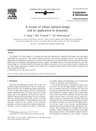
Figure 19: Lift and moment coefficients φ w = 0 ◦ .<br />
CL<br />
0.23<br />
0.225<br />
0.22<br />
Cmac<br />
1.24<br />
1.23<br />
1.22<br />
1.21<br />
1.2<br />
1.19<br />
θ p = 0 ◦<br />
θ p = 15 ◦<br />
θ p = 30 ◦<br />
θ p = 45 ◦<br />
θ p = 60 ◦<br />
θ p = 75 ◦<br />
θ p = 90 ◦<br />
V + = V − =0<br />
0.215<br />
1.18<br />
0 10 20 30 40 50 60 70 80 90<br />
0 10 20 30 40 50 60 70 80 90<br />
θ S θ S<br />
Figure 20: Lift and moment coefficients φ w = 15 ◦ .<br />
ratio 0.33, and 1.9 m of span, b. The wing box has a structural chord that is 50% of the local aerodynamic<br />
chord, while the depth is 7% of it. A hinge placed at 75% of the span, splits the the wing in to an inner<br />
(the baseline) and an outer (the winglet) portion. The hinge angle φ w , and thus the winglet position, can be<br />
varied by means of a torque actuator. A total number of 5 ribs, equally spaced, are placed within the baseline,<br />
while 3 ribs are allocated <strong>for</strong> the winglet. The wing box is entirely realised in Kevlar Epoxy composite (see<br />
Tab. 6). All the ticknesses are set to 1 mm, while the cap areas are set to 25 × 10 −6 m 2 . The wing is set to<br />
fly at a speed of U ∞ = 30 m/s and at an angle of attack α = 3 ◦ . The aerodynamic loads are based on 10<br />
panels <strong>for</strong> inner wing and 6 on the outer. The flow features are given in Tab. 5. An overall structural and<br />
aerodynamic symmetry condition about the x-z plane is assumed.<br />
A type of piezoceramic composite actuator commonly known as the Macro Fiber Composite (MFC) actuator<br />
is used <strong>for</strong> the present simulations. The MFC actuator, developed at NASA Langley Research Center, 42<br />
is a layered, planar actuation device that employs rectangular cross-section, unidirectional piezoceramic<br />
fibers (PZT 5A) embedded in a thermosetting polymer matrix. This active, fiber rein<strong>for</strong>ced layer is then<br />
sandwiched between copper-clad Kapton film layers that have an etched interdigitated electrode pattern.<br />
Because of the in-plane poling the MFC uses the d 33 piezoelectric effect, which is much stronger than the d 31<br />
effect used by traditional PZT actuators with through-the-thickness poling. The theory developed in Sec. III<br />
can be easily extended to the case of MFC patches simply considering, as voltage actuation input parameter<br />
V/t, the distance between the in-plane electrodes ∆χ in place of the patch thickness t. The MFC patches<br />
work in a voltage range of -500 to 1500 V and the main parameters are given in Tab. 7. 43 Implementation<br />
of MFC patches <strong>for</strong> the control of a small manned aircraft has been successfully done by Bilgen et al. 4<br />
A total number of four MFC patches of dimension 0.056×0.085 m, are placed on the winglet. Specifiacally,<br />
two of them are placed on the upper surface, along the elastic axis direction, and loaded with the maximum<br />
positive voltage of 1500 V; the other two are placed on the lower skin and loaded with the maximum negative<br />
voltage -500 V. The goal is to investigate the effect of the skin and piezo-patches composite-web orientations,<br />
identified by the angles θ s and θ p respectively, on the aerodynamic coefficients. The local material coordinate<br />
system of the skin and the piezo-patches are given in Fig. 17, while a scheme of the whole configuration<br />
20 of 23<br />
American Institute of Aeronautics and Astronautics