Optimal Design of Elastomer Composites for ... - Michael I Friswell
Optimal Design of Elastomer Composites for ... - Michael I Friswell
Optimal Design of Elastomer Composites for ... - Michael I Friswell

Create successful ePaper yourself
Turn your PDF publications into a flip-book with our unique Google optimized e-Paper software.
Proceedings <strong>of</strong> the ASME 2011 Conference on Smart Materials, Adaptive Structures and Intelligent Systems<br />
SMASIS2011<br />
September 18-21, 2011, Scottsdale, Arizona, USA<br />
Proceedings <strong>of</strong> the ASME 2011 Conference on Smart Materials, Adaptive Structures and<br />
Intelligent Systems<br />
SMASIS2011-<br />
SMASIS2011<br />
September 18-21, 2011, Scottsdale, Arizona, USA<br />
SMASIS2011-5021<br />
OPTIMAL DESIGN OF ELASTOMER COMPOSITES FOR MORPHING SKINS<br />
Senthil Murugan ∗ Erick I. Saavedra Flores <strong>Michael</strong> I. <strong>Friswell</strong> Sondipon Adhikari<br />
College <strong>of</strong> Engineering<br />
Swansea University<br />
Swansea, SA2 8PP<br />
UK<br />
ABSTRACT<br />
Morphing aircraft concepts aim to enhance the aircraft per<strong>for</strong>mance<br />
over multiple missions by designing time variant wing<br />
configurations. The morphing concepts require wing skins that<br />
are flexible enough to allow large in-plane stretching and high<br />
bending stiffness to resist the aerodynamic loads. In this study,<br />
an optimization problem is <strong>for</strong>med to enhance the in-plane flexibility<br />
and bending stiffness <strong>of</strong> wing skins modeled as composite<br />
plates. Initially, the optimal fiber and elastomer materials <strong>for</strong><br />
highly flexible fiber rein<strong>for</strong>ced elastomer laminates are studied<br />
using materials available in the literature. The minor Poisson’s<br />
ratio <strong>of</strong> the laminate is almost zero <strong>for</strong> all the fiber and elastomer<br />
combinations. In the next stage, the effects <strong>of</strong> boundary conditions<br />
and aspect ratio on the out-<strong>of</strong>-plane deflection <strong>of</strong> the laminate<br />
are studied. Finally, an optimization is per<strong>for</strong>med to minimize<br />
the in-plane stiffness and maximize the bending stiffness by<br />
spatially varying the volume fraction <strong>of</strong> fibers <strong>of</strong> a laminate. The<br />
optimization results show that the in-plane flexibility and bending<br />
stiffness <strong>of</strong> the laminate with a variable fiber distribution is<br />
30-40% higher than <strong>for</strong> the uni<strong>for</strong>m fiber distribution.<br />
NOMENCLATURE<br />
δ In-plane displacement <strong>of</strong> the plate.<br />
∆ Out-<strong>of</strong>-plane displacement <strong>of</strong> the plate.<br />
u x,y,z Displacements in the x, y and z directions.<br />
Rotations with the x, y and z axis.<br />
θ x,y,z<br />
∗ s.m.masanam@swansea.ac.uk.<br />
INTRODUCTION<br />
In recent years, considerable research has focussed on designing<br />
aircraft wings which can reconfigure their initial wing<br />
shape to the optimal shape <strong>of</strong> a specific flight regime. The aircraft<br />
wings capable <strong>of</strong> such a reconfiguration in shape in flight,<br />
are termed morphing wings. The possible morphing wing abilities<br />
include variable sweep, dihedral position, chamber change,<br />
wing chord change and wing span change. One <strong>of</strong> the key challenges<br />
in developing a successful morphing wing is the development<br />
<strong>of</strong> morphing skin that is a continuous layer <strong>of</strong> material that<br />
would stretch over the morphing structure to <strong>for</strong>m a smooth aerodynamic<br />
surface. Most research on morphing skin technology [1]<br />
can be broadly classified under three major areas: Compliant<br />
structures, shape memory polymers (SMPs) and anisotropic elastomeric<br />
skins.<br />
Compliant structures rely on the internal structure <strong>of</strong> aircraft<br />
wing to allow small amounts <strong>of</strong> trailing edge camber change [1].<br />
This morphing technology requires only small de<strong>for</strong>mations and<br />
there<strong>for</strong>e, conventional metal or resin-matrix-composite skin materials<br />
can be used to carry aerodynamic loads. Bi-stable laminated<br />
composite and corrugated skins are few examples <strong>of</strong> complaint<br />
structures.<br />
SMP skin materials have received considerable attention<br />
<strong>for</strong> morphing aircraft wing concepts, and are suited to spanextension<br />
type morphing applications. Shape memory polymers<br />
exhibit an order <strong>of</strong> magnitude reduction in modulus and up to<br />
200% strain capability when heated past a transition temperature,<br />
yet return to their original modulus upon cooling. However,<br />
1 Copyright c⃝ 2011 by ASME
the SMPs have following disadvantages <strong>for</strong> a large scale wing<br />
morphing [2]: 1) Electrical heating <strong>of</strong> the SMP skin to reach<br />
transition temperature can be difficult. 2) The time required <strong>for</strong><br />
heating SMP material to transition can be ill-suited to dynamic<br />
control morphing objectives. 3) A temperature dependent morphing<br />
mechanism in aircraft wings which are filled with fuels<br />
could be catastrophic.<br />
<strong>Elastomer</strong>ic materials can be ideal candidates <strong>for</strong> the morphing<br />
skin applications [3]. High strain capability, lower degree <strong>of</strong><br />
risk due to their passive operation, elastic recovery with nominal<br />
strain values and a smooth aerodynamic surface <strong>of</strong> elastomers<br />
are advantageous <strong>for</strong> morphing skins. These materials include<br />
thermoplastic polyurethanes, copolyester elastomer, and woven<br />
materials made from elastane yarns. A very few studies have<br />
investigated the elastomeric skins tailored specifically <strong>for</strong> spanmorphing<br />
applications with a suitable supporting substructure to<br />
withstand aerodynamic loads.<br />
Peel et al. [3] developed a wing skin, actuator, and actuator<br />
attachment <strong>for</strong> a simple morphing wing. Upper and lower<br />
wing skins were fabricated with carbon fiber/polyurethane elastomer<br />
laminates. Three pneumatic rubber muscle actuators were<br />
used to provide the required actuation. An elastic camber down<br />
<strong>of</strong> 25 o at the nose and 20 o at the tail were achieved. Bubert et<br />
al. [2] studied the properties <strong>of</strong> various silicone elastomers <strong>for</strong><br />
the morphing skins. The most promising silicone elastomer was<br />
Rhodorsils V-330 CA-45 which had the right combination <strong>of</strong><br />
low viscosity and long work time to enable easy and effective<br />
fiber-rein<strong>for</strong>ced elastomer composite (FMC) manufacture, and<br />
demonstrated high maximum elongation and tear strength.<br />
Kikuta [4] investigated the mechanical properties <strong>of</strong> elastomers<br />
that could be used as a skin <strong>for</strong> morphing wings. The<br />
materials tested were thermoplastic polyurethanes, copolyester<br />
elastomer, woven materials and shape memory polymers. The<br />
materials which strained well and required less <strong>for</strong>ce, could not<br />
sustain high pressure loads. The materials that did not strain<br />
well and required more actuation <strong>for</strong>ce were able to handle a<br />
larger sustained pressure load. Finally, the study suggested that<br />
Tec<strong>of</strong>lex 80A was the best elastomer <strong>for</strong> morphing skin applications.<br />
Another key area <strong>of</strong> research is the design and optimization<br />
<strong>of</strong> laminates <strong>for</strong> morphing applications. With the conflicting objectives<br />
<strong>of</strong> low in-plane stiffness, high out-<strong>of</strong>-plane bending stiffness<br />
and zero Poisson’s ratio, the nature <strong>of</strong> design variables selected<br />
<strong>for</strong> optimization has to be different from that <strong>of</strong> conventional<br />
composite structures. For example, the conventional composite<br />
laminates are made <strong>of</strong> plies with the fibers being straight,<br />
parallel and uni<strong>for</strong>mly spaced. However, <strong>for</strong> a morphing skin<br />
application, the curvilinear fiber-<strong>for</strong>mat, termed as variable stiffness<br />
laminates, can be beneficial as it can decouple the conflicting<br />
requirements <strong>of</strong> morphing skins. Gurdal et al. [5] demonstrated<br />
that the variable stiffness concept provides flexibility to<br />
the designer <strong>for</strong> trade-<strong>of</strong>fs between overall panel stiffness and<br />
buckling load, in that there exist many configurations with equal<br />
buckling loads yet different global stiffness values, or vice versa.<br />
Similar to the curvilinear fiber orientations, another important<br />
parameter is the volume fraction <strong>of</strong> fibers in a composite<br />
laminate. Martin and Leissa [6] investigated the plane stress<br />
problem <strong>of</strong> a composite laminate with spatially varying volume<br />
fractions <strong>of</strong> fibers. The fiber redistribution increased the buckling<br />
load by as much as 38%. Benatta et al. [7] demonstrated the<br />
improvements in the structural properties <strong>of</strong> beams by creating<br />
functionally graded materials (FGM) in the <strong>for</strong>m <strong>of</strong> a symmetric<br />
composite whose fiber volume fraction varies through the thickness.<br />
Kuo and Shiau [8] studied the buckling and vibration <strong>of</strong><br />
composite laminated plates with variable fiber spacing using the<br />
finite element method. The results indicated that more fibers distributed<br />
in the central portion <strong>of</strong> the plate can efficiently increase<br />
the buckling load and natural frequencies. Most <strong>of</strong> these studies<br />
have focussed on the vibration and buckling per<strong>for</strong>mance <strong>of</strong><br />
laminates. However, the same design parameters <strong>of</strong> curvilinear<br />
fibers and variable volume fraction <strong>of</strong> fibers can also be used to<br />
achieve some <strong>of</strong> the design requirements <strong>of</strong> morphing skins, and<br />
is the aim <strong>of</strong> this study. In this work, two essential features <strong>of</strong><br />
morphing skins are studied. In the first part, the optimal combination<br />
<strong>of</strong> fiber and elastomer matrix available <strong>for</strong> morphing wing<br />
skins are studied. The second part involves an optimization process<br />
to find the optimal distribution <strong>of</strong> volume fraction <strong>of</strong> fibers<br />
in a laminate to minimize the in-plane stiffness and maximize the<br />
out-<strong>of</strong>-plane stiffness, simultaneously.<br />
ELASTOMER MATERIAL SELECTION<br />
The wing span extension type morphing mechanisms require<br />
the in-plane stretching <strong>of</strong> wing skins to be more than 25% strain<br />
without failure. Conventional fiber rein<strong>for</strong>ced epoxy laminates<br />
have tensile failure strains in the range <strong>of</strong> 1 to 2% in the fiber direction<br />
and transverse tensile failure strains <strong>of</strong> around 0.5% [9].<br />
The elastomers are one <strong>of</strong> the few materials that can undergo<br />
strains more than 25% without failure. In this section, the lamina<br />
material properties are studied with various elastomers as the<br />
matrix and fibers available in the literature.<br />
The lamina properties are evaluated with a micromechanical<br />
model based on the rule <strong>of</strong> mixtures [10]. This study<br />
finds optimal material properties and highlights issues related to<br />
the design <strong>of</strong> fiber rein<strong>for</strong>ced elastomer laminates. The fibers<br />
and elastomer material properties collected from the literature<br />
are given in Tables 1 and 2. The graphite and kevlar fibers are<br />
transversely isotropic and the glass, boron, and silicon fibers<br />
are isotropic. However, the elastomer laminate stiffness, similar<br />
to the epoxy laminates, are controlled by the longitudinal<br />
modulus <strong>of</strong> the fibers rather than its transverse modulus properties.<br />
The combination <strong>of</strong> longitudinal modulus and Poisson’s<br />
ratio can play a major role in selecting the fibers <strong>for</strong> a morphing<br />
skin. The elastomeric material properties are collected from<br />
2 Copyright c⃝ 2011 by ASME
the references [3, 4]. Kikuta [4] gave the mechanical properties<br />
<strong>of</strong> tec<strong>of</strong>lex, riteflex and arnitel elastomers which are linear <strong>for</strong><br />
strains up to 25% and exhibit non-linear properties after that. The<br />
properties <strong>of</strong> these materials corresponding to the linear range<br />
are given in Table 2. However, the urethane material properties<br />
collected from reference [3] do not mention its strain behavior.<br />
These preliminary results shows that the FRE composites<br />
satisfy the stiffness and Poisson’s ratio requirements desirable<br />
<strong>for</strong> the morphing skins. However, the factors that can control the<br />
selection <strong>of</strong> elastomers are the non-linear stress-strain property,<br />
the elastic recovery, the fiber-elastomer bonding and the thermal<br />
properties.<br />
TABLE 1.<br />
FIBER PROPERTIES<br />
Material E 1 E 2 ν 12 G 12<br />
(GPa) (GPa) (GPa)<br />
FIGURE 1.<br />
1<br />
θ<br />
2<br />
In-plane stretching<br />
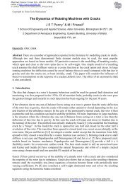
FIBER REINFORCED ELASTOMER LAMINA<br />
The longitudinal Young’s modulus, lateral modulus, major<br />
and minor Poissons’s ratio <strong>of</strong> the fiber rein<strong>for</strong>ced elastomer<br />
(FRE) lamina as shown in Fig. 1 is calculated with the rule<br />
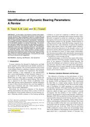
<strong>of</strong> mixtures and are shown in Figs. 2 and 3. The longitudinal<br />
Young’s modulus <strong>of</strong> the lamina which is the main parameter <strong>for</strong><br />
out-<strong>of</strong>-plane bending strength, varies from 20 to 220 GPa. The<br />
lateral Young’s modulus, a parameter corresponding to the inplane<br />
stretching <strong>of</strong> the fiber rein<strong>for</strong>ced elastomer skins, varies<br />
from 10 to 400 MPa, which is <strong>of</strong> the order <strong>of</strong> 10 3 less than the<br />
longitudinal modulus. The shear modulus also varies in a similar<br />
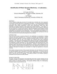
way to the lateral Young’s modulus. The major Poisson’s<br />
ratio <strong>of</strong> the FRE lamina varies from 0.2 to 0.55 as shown in<br />
Fig. 3(a). Peel has shown that the in-plane Poisson’s ratios <strong>of</strong><br />
FRE can reach higher than 32 and less than -60 [11]. However,<br />
<strong>for</strong> a wing span extension type morphing mechanism, the major<br />
Poisson’s ratio does not play a major role whereas the minor<br />
Poisson’s ratio has to be small. The minor Poisson’s ratio <strong>of</strong> the<br />
FRE lamina shown in Fig. 3(b) is <strong>of</strong> the order <strong>of</strong> 10 −3 <strong>for</strong> any<br />
fiber and elastomer combination. This is expected <strong>for</strong> a highly<br />
orthotropic material as the minor Poisson’s ratio depends on the<br />
ratio <strong>of</strong> transverse to longitudinal modulus, as given in Eqn. (1),<br />
which is <strong>of</strong> the order <strong>of</strong> 10 −3 <strong>for</strong> the FRE composites considered.<br />
υ 21 = E 2<br />
E 1<br />
υ 12 (1)<br />
Kevlar (29) 61 4.2 0.35 2.9<br />
Glass 71 71 0.22 30<br />
Kevlar (49) 154 4.2 0.35 2.9<br />
Graphite (AS) 224 14 0.2 14<br />
Saffil 300 300 0.2 126<br />
Graphite (HMS) 385 6.3 0.2 7.7<br />
Al 2 O 3 385 385 0.3 154<br />
SiC 406 406 0.2 169<br />
Boron 420 420 0.2 170<br />
TABLE 2. MATRIX PROPERTIES<br />
Material E 1 ν 12 G 12 @ Strain (%)<br />
(MPa) (MPa)<br />
Silicone rubber 0.916 0.50 0.3053 -<br />
Tec<strong>of</strong>lex 80A 1.07 0.75 0.3057 21.3<br />
RP6410 urethane 1.65 0.50 0.549 -<br />
RP6442 urethane 6.095 0.50 2.034 -<br />
Tec<strong>of</strong>lex 100A 16.6 0.50 5.5333 20.8<br />
Arnitel 640A 23.5 0.33 8.8346 23.7<br />
Riteflex 640A 35.8 0.60 11.1875 22.2<br />
RP6444 urethane 182 0.50 60.6 -<br />
Typical epoxy 2096 0.30 806 3-4 (failure)<br />
3 Copyright c⃝ 2011 by ASME
x 10 5<br />
Lamina E1, (MPa)<br />
2.5<br />
2<br />
1.5<br />
1<br />
0.5<br />
0<br />
Boron<br />
SiCon<br />
GrpHS<br />
Al2O3<br />
Safil<br />
GrpAS<br />
Kev49<br />
Glass<br />
Fibers Kev29<br />
RP6444urtn<br />
Ritflx640A<br />
Arntel640A<br />
Tecflx100A<br />
RP6442urtn<br />
RP6410urtn<br />
Tecflx080A<br />
Silcoruber<br />
<strong>Elastomer</strong>s<br />
(a) LONGITUDINAL YOUNG’S MODULUS<br />
Major Poissons ratio v 12<br />
0.7<br />
0.6<br />
0.5<br />
0.4<br />
0.3<br />
0.2<br />
Boron<br />
SiCon<br />
GrpHS<br />
Al2O3<br />
Safil<br />
GrpAS<br />
Kev49<br />
Glass<br />
Fibers Kev29<br />
RP6444urtn<br />
Ritflx640A<br />
Arntel640A<br />
Tecflx100A<br />
RP6442urtn<br />
RP6410urtn<br />
Tecflx080A<br />
Silcoruber <strong>Elastomer</strong>s<br />
(a) MAJOR POISSON’S RATIO<br />
400<br />
Lamina E2, (MPa)<br />
300<br />
200<br />
100<br />
0<br />
Boron<br />
SiCon<br />
GrpHS<br />
Al2O3<br />
Safil<br />
GrpAS<br />
Kev49<br />
Glass<br />
Fibers Kev29<br />
RP6444urtn<br />
Ritflx640A<br />
Arntel640A<br />
Tecflx100A<br />
RP6442urtn<br />
RP6410urtn<br />
Tecflx080A<br />
Silcoruber<br />
<strong>Elastomer</strong>s<br />
(b) LATERAL YOUNG’S MODULUS<br />
FIGURE 2. MODULUS PROPERTIES OF LAMINA FOR VARI-<br />
OUS FIBER AND ELASTOMER MATERIALS FOR STRAINS LESS<br />
THAN 25%<br />
Minor Poissons ratio v 21<br />
5<br />
4<br />
3<br />
2<br />
1<br />
x 10 −3<br />
0<br />
Boron<br />
SiCon<br />
GrpHS<br />
Al2O3<br />
Safil<br />
GrpAS<br />
Kev49<br />
Glass<br />
Fibers Kev29<br />
RP6444urtn<br />
Ritflx640A<br />
Arntel640A<br />
Tecflx100A<br />
RP6442urtn<br />
RP6410urtn<br />
Tecflx080A<br />
Silcoruber <strong>Elastomer</strong>s<br />
(b) MINOR POISSON’S RATIO<br />
FIGURE 3. POISSON’S RATIO OF LAMINA FOR VARIOUS<br />
FIBER AND ELASTOMER MATERIALS FOR STRAINS LESS<br />
THAN 25%<br />
HOMOGENISATION-BASED MULTI-SCALE CONSTITU-<br />
TIVE MODEL<br />
The main assumption in the homogenisation-based multiscale<br />
constitutive theory <strong>of</strong> heterogenous solids is that the macroscopic<br />
or homogenised strain tensor ε at any arbitrary point x <strong>of</strong><br />
the macroscopic continuum is the volume average <strong>of</strong> the microscopic<br />
strain tensor field ε µ defined over a local representative<br />
volume element (RVE). The RVE is such that its domain Ω µ has<br />
a characteristic length much smaller than that <strong>of</strong> the macroscopic<br />
continuum and, at the same time, is sufficiently large to represent<br />
the mechanical behaviour <strong>of</strong> the heterogeneous medium in the<br />
averaged sense.<br />
At any instant t, the macroscopic or homogenised strain ten-<br />
sor ε at a point x can be expressed as<br />
ε(x,t) = 1<br />
V µ<br />
∫<br />
Ω µ<br />
ε µ (y,t)dV, (2)<br />
where V µ is the volume <strong>of</strong> the RVE associated to point x, y denotes<br />
the local RVE coordinates and ε µ = ∇ s u µ , with ∇ s denoting<br />
the symmetric gradient operator and u µ the RVE (or microscropic)<br />
displacement field.<br />
Further, it is possible to decompose the displacement field<br />
u µ as a sum <strong>of</strong> a linear displacement ε(x,t)y, which represents<br />
a homogeneous strain, and a displacement fluctuation field ũu µ ,<br />
4 Copyright c⃝ 2011 by ASME
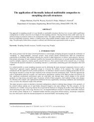
FIGURE 4.<br />
i.e.,<br />
REPRESENTATIVE VOLUME ELEMENT (RVE).<br />
u µ (y,t) = ε(x,t)y + ũu µ (y,t). (3)<br />
The displacement fluctuations field represents local variations<br />
about the linear displacement ε(x,t)y and do not contribute to<br />
the macroscopic scale strain. The field ũu µ depends on the presence<br />
<strong>of</strong> heterogeneities within the RVE.<br />
In general, the present multi-scale constitutive theory requires<br />
the prescription <strong>of</strong> kinematical constraints upon the selected<br />
RVE. In what follows, the choice <strong>of</strong> this set <strong>of</strong> kinematical<br />
constraints will coincide with the widely used Periodic boundary<br />
displacement fluctuations model. This is typically associated<br />
with the modelling <strong>of</strong> periodic media. The fundamental kinematical<br />
assumption in this class <strong>of</strong> constitutive models consists<br />
in prescribing identical displacement fluctuation vectors <strong>for</strong> each<br />
pair <strong>of</strong> opposite points {y + , y − } on the RVE boundary ∂Ω µ , such<br />
that:<br />
ũu µ (y + ,t) = ũu µ (y − ,t) ∀ {y + , y − } ∈ ∂Ω µ . (4)<br />
The adopted RVE in the present work is shown in Figure<br />
4. We consider a periodic linear elastic medium with a circular<br />
rein<strong>for</strong>cing fibre located in the centre <strong>of</strong> the RVE, embedded<br />
in a s<strong>of</strong>ter matrix. The volume fraction <strong>of</strong> rein<strong>for</strong>cement considered<br />
here are: 20, 30, 40, 50 and 60 %. The finite element<br />
implementation <strong>of</strong> the homogenisation scheme was carried out<br />
in ANSYS [12]. For further details about computer implementation<br />
<strong>of</strong> this type <strong>of</strong> models, we refer, <strong>for</strong> instance, to [13, 14].<br />
Three-dimensional solid structural elements (Solid45) were used<br />
in all the RVE finite element meshes. The lamina mechanical<br />
properties <strong>for</strong> volume fractions <strong>of</strong> fibers between 20% and 60%<br />
are calculated with the graphite fibre and epoxy matrix materials<br />
given in Table 1 and 2.<br />
modeled as plates is different from the isotropic plates. There<strong>for</strong>e,<br />
be<strong>for</strong>e per<strong>for</strong>ming the optimization, the effects <strong>of</strong> aspect<br />
ratio on the out-<strong>of</strong>-plane deflection <strong>of</strong> skin panels modeled as<br />
plates are studied in this section.<br />
An aluminium plate and a composite plate with the same<br />
structural dimensions are considered. The composite plate is<br />
made <strong>of</strong> graphite fibers and epoxy matrix given in Tables 1 and 2.<br />
Two possible boundary conditions representative <strong>of</strong> the morphing<br />
skin are considered. In the first case, the boundary conditions<br />
<strong>of</strong> the plate are simply supported at two sides and fixed at other<br />
two sides (SS-FF). In the second case, the boundary condition<br />
<strong>of</strong> the plate are fixed at all four sides (FF-FF). In the first case,<br />
the fibers <strong>of</strong> the composite plate are parallel to the fixed edges.<br />
This represents a morphing skin which is allowed to morph in<br />
the spanwise direction.<br />
The maximum deflection due to uni<strong>for</strong>m pressure loading is<br />
evaluated with the ANSYS <strong>for</strong> aspect ratios varying from 0.5 to<br />
2.0. The percentage increase in the maximum deflection <strong>for</strong> different<br />
aspect ratios compared to the maximum deflection at an<br />
aspect ratio <strong>of</strong> 1.0 is calculated and are shown in Figs. 5 and<br />
6. The results show that the deflection <strong>of</strong> an isotropic plate increases<br />
almost 100% with an increase in the aspect ratio from<br />
1 to 2 in the FF-FF boundary condition. Further, the increase<br />
in deflection converges around the aspect ratio <strong>of</strong> 2.0. However,<br />
<strong>for</strong> the orthotropic plate, the deflection remains constant with the<br />
increase in aspect ratio (L/B ratio), whereas it increases dramatically<br />
with the L/B ratio less than 1. For example, the deflection<br />
increases by 600% <strong>for</strong> the L/B ratio <strong>of</strong> 0.5 as shown in Fig. 5.<br />
For the SS-FF boundary condition case, the deflection <strong>of</strong> orthotropic<br />
plate increases to almost 30% when the aspect ratio<br />
reaches 1.5 and remains relatively constant after that, as shown<br />
in Fig. 6. As the composite fibers are in the direction perpendicular<br />
to the simply supported boundary conditions, the change from<br />
a square plate to a rectangular plate has little effect on the composite<br />
plates <strong>for</strong> a L/B ratio greater than 1. However, when the<br />
aspect ratio is less than 1, the deflection <strong>of</strong> the composite plate increases<br />
dramatically compared to the isotropic plate. This is due<br />
to the fact that E 2 , which is much less than E 1 <strong>for</strong> the composite<br />
plate, plays a major role in the out-<strong>of</strong>-plane bending <strong>for</strong> aspect<br />
ratios less than 1. Note, the thickness <strong>of</strong> the plate is kept constant<br />
<strong>for</strong> all the aspect ratios. These results show that the optimal design<br />
<strong>of</strong> plates can vary with the aspect ratio <strong>of</strong> plates. There<strong>for</strong>e,<br />
the optimization has to be per<strong>for</strong>med <strong>for</strong> different aspect ratios.<br />
In the following sections, the optimization is per<strong>for</strong>med to find<br />
the optimal distribution <strong>of</strong> composite fibers <strong>of</strong> the plate with the<br />
aspect ratios <strong>of</strong> 1.0, 1.3, 2.0 and 4.0.<br />
OUT-OF-PLANE DEFLECTION<br />
The morphing wing skin panels can be modeled with different<br />
aspect ratios (ARs) and with different possible boundary conditions.<br />
Also, the deflection behavior <strong>of</strong> orthotropic skin panels<br />
OPTIMIZATION FORMULATION<br />
In this section, an optimization is per<strong>for</strong>med to find the optimal<br />
fiber distributions <strong>of</strong> composite plates representative <strong>of</strong> morphing<br />
skins. The objective is to maximize the ratio <strong>of</strong> in-plane<br />
5 Copyright c⃝ 2011 by ASME
% change in deflection<br />
800<br />
700<br />
600<br />
500<br />
400<br />
300<br />
200<br />
100<br />
Isotropic<br />
Orthotropic<br />
U x,y,z = 0<br />
x,y,z = 0<br />
B<br />
U x,z = 0<br />
Z<br />
Y<br />
X<br />
Uni<strong>for</strong>m pressure<br />
In-plane<br />
loading<br />
U x,z = 0<br />
x,y,z = 0<br />
0<br />
−100<br />
0.5 1 1.5 2<br />
Aspect ratio (L/B)<br />
U x, z = 0<br />
L<br />
FIGURE 5. EFFECTS OF ASPECT RATIO ON THE OUT-OF-<br />
PLANE DISPLACEMENT FOR A PLATE WITH FF-FF CONDI-<br />
TIONS<br />
FIGURE 7.<br />
BOUNDARY CONDITIONS OF LAMINATE<br />
800<br />
700<br />
Isotropic<br />
Orthotropic (fibers parallel to FF boundaries)<br />
% change in deflection<br />
600<br />
500<br />
400<br />
300<br />
200<br />
100<br />
0<br />
0.5 1 1.5 2 2.5 3 3.5 4<br />
Aspect ratio (L/B)<br />
FIGURE 6. EFFECTS OF ASPECT RATIO ON THE OUT-OF-<br />
PLANE DISPLACEMENT FOR A PLATE WITH SS-FF CONDI-<br />
TIONS<br />
B = 100<br />
mm<br />
T =0.2<br />
mm<br />
x<br />
<br />
L = 100, 130, 200, 400 mm<br />
X1 X2 X3 X4 X5 X4 X3 X2 X1<br />
X6 X7 X8 X9 X10 X9 X8 X7 X6<br />
y<br />
stretching <strong>of</strong> the laminate to the bending stiffness by varying the<br />
volume fraction <strong>of</strong> fibers <strong>for</strong> the plies. The optimization is per<strong>for</strong>med<br />
<strong>for</strong> two cases. In the first case, the maximum out-<strong>of</strong>-plane<br />
deflection <strong>for</strong> a given uni<strong>for</strong>m pressure loading is minimized by<br />
varying the fiber volume distribution. In the second case, the<br />
ratio <strong>of</strong> in-plane displacement to the maximum out-<strong>of</strong>-plane displacement<br />
is maximized. That is the laminate is optimized to be<br />
flexible along the in-plane direction and at the same time stiffened<br />
enough to minimize the out-<strong>of</strong>-plane deflection due to uni<strong>for</strong>m<br />
pressure loading.<br />
The boundary conditions <strong>of</strong> a laminate representative <strong>of</strong> a<br />
morphing skin is considered in this study and shown in Fig. 7.<br />
The plate is divided into 9 sections along the length ’L’, as shown<br />
in Fig. 8. The term aspect ratio or L/B ratio is interchangeable in<br />
the following discussions. A symmetric balanced laminate with<br />
four plies is considered in this study. The design variables X 1<br />
to X 10 , shown in Fig. 8, represent the volume fraction <strong>of</strong> fibers.<br />
The upper and lower limits <strong>of</strong> the volume fraction <strong>of</strong> fibers in a<br />
laminate depends on the fiber packing and failure modes [10,15].<br />
FIGURE 8. LAMINATE WITH VOLUME FRACTION OF FIBERS<br />
AS DESIGN VARIABLES<br />
In this study, the design variables are allowed to vary between 20<br />
to 60% volume fraction <strong>of</strong> fibers with a 5% increment. However,<br />
the average volume fraction <strong>of</strong> the laminate is kept at 40%. That<br />
is the fibers <strong>of</strong> a plate with the uni<strong>for</strong>m volume fraction <strong>of</strong> 40%<br />
is redistributed to improve its structural efficiency. A uni<strong>for</strong>m<br />
pressure <strong>of</strong> 50 Pa is applied to the surface and a uni<strong>for</strong>m in-plane<br />
loading <strong>of</strong> 1 N/mm is applied along the edge <strong>of</strong> the plate. The<br />
maximum out-<strong>of</strong>-plane displacement and in-plane displacement<br />
<strong>for</strong> the given loadings are calculated with ANSYS. The laminate<br />
is modeled with shell99A elements <strong>for</strong> which the number <strong>of</strong> ply<br />
layers, ply angles and material properties <strong>of</strong> each layer are given<br />
as input.<br />
The objective function to minimize the maximum out-<strong>of</strong>plane<br />
displacement <strong>of</strong> the plate and constraints <strong>for</strong> the optimiza-<br />
6 Copyright c⃝ 2011 by ASME
tion case I can be written as<br />
The constraint is<br />
Minimize,<br />
g(X) =<br />
n<br />
∑<br />
i=1<br />
[ ] ∆(X)<br />
max<br />
(X i )<br />
n<br />
∆ max<br />
40<br />
(5)<br />
= 40% (6)<br />
where ∆(X) max is the maximum out-<strong>of</strong>-plane displacement <strong>of</strong><br />
plate and the X i are the design variables, that is the volume fraction<br />
<strong>of</strong> fibers (%). The displacement ∆ max<br />
40<br />
denotes the value<br />
corresponding to the plate with uni<strong>for</strong>m fiber volume fraction<br />
<strong>of</strong> 40%. Thus the uni<strong>for</strong>m fiber distribution with 40% volume<br />
fraction is considered as the baseline design.<br />
Similarly, the objective function to minimize the maximum<br />
out-<strong>of</strong>-plane displacement <strong>of</strong> the plate and maximize the in-plane<br />
displacement <strong>for</strong> optimization case II can be written as<br />
Maximize,<br />
[ ( ) ( δ(X) ∆<br />
max<br />
)]<br />
40<br />
w 1 + w 2<br />
δ 40 ∆(X) max<br />
where δ(X) is the in-plane displacement <strong>of</strong> the plate, and w 1 and<br />
w 2 are the weights <strong>of</strong> the functions. Here, the two objective functions<br />
are combined to <strong>for</strong>m a single aggregate objective function<br />
using the weighted linear sum <strong>of</strong> the objectives method. In this<br />
study, equal weights are assigned to both the objective functions,<br />
i.e., w 1 = 0.5 and w 2 = 0.5. The optimization case II has the<br />
same constraint as given in Eqn. (6). The ply angle values are<br />
assigned to be zero while optimizing the fiber distribution. It<br />
is likely that the optimal ply angle values will be zero <strong>for</strong> the<br />
boundary conditions and objective function <strong>of</strong> this problem.<br />
The optimization is per<strong>for</strong>med with a real coded genetic algorithm<br />
(GA) coupled with the ANSYS <strong>for</strong> objective function<br />
evaluations [16]. The optimization was per<strong>for</strong>med with a population<br />
size <strong>of</strong> 40 and 200 generations was used as the stoping<br />
criteria based on the computational time. The main issue, in<br />
terms <strong>of</strong> computational time, in this optimization study was the<br />
implementation <strong>of</strong> constraints given in Eqn. (6). The constraint<br />
requires the average value each potential design, i.e., the average<br />
<strong>of</strong> volume fraction <strong>of</strong> the fibers, to be equal to 40%. However,<br />
the GA creates the new designs which may not satisfy the constraints,<br />
thereby increasing the number <strong>of</strong> generations to find the<br />
optimal solution.<br />
OPTIMIZATION CASE I. The optimization is per<strong>for</strong>med<br />
<strong>for</strong> aspect ratios <strong>of</strong> 1.0, 1.3, 2.0 and 4.0. The results <strong>of</strong> the optimization<br />
case I are shown in Fig. 9 and Table 3. The optimal<br />
(7)<br />
fiber distribution <strong>for</strong> the AR <strong>of</strong> 1.0 shows that the top ply has almost<br />
60% volume fraction (VF) and the second ply has 20% VF.<br />
For the AR <strong>of</strong> 1.3, the optimal result shows a parabolic type distribution<br />
<strong>for</strong> both the ply layers with almost 30% VF at the edges<br />
and reaching 60% at the middle <strong>of</strong> the plate length, L. For the AR<br />
<strong>of</strong> 2.0, the optimal distribution <strong>of</strong> the top ply shows a parabolic<br />
type distribution whereas the second layer shows a dual peak type<br />
distribution. Similarly, <strong>for</strong> the AR <strong>of</strong> 4.0, the fiber volume distribution<br />
has multiple peaks <strong>for</strong> both <strong>of</strong> the ply layers.<br />
The maximum out-<strong>of</strong>-plane deflections <strong>of</strong> optimal fiber distributions<br />
are compared with the maximum out-<strong>of</strong>-plane deflections<br />
<strong>of</strong> uni<strong>for</strong>m fiber distributions and given in Table 3. In addition<br />
to the optimal case and uni<strong>for</strong>m fiber distribution case, the<br />
fiber distribution <strong>of</strong> 60% VF at the top layer and 20% VF at the<br />
second layer, so that the average VF is 40%, is also given in Table<br />
3. For easy comparison, all deflections are normalized with the<br />
deflections <strong>of</strong> the uni<strong>for</strong>m fiber distribution (∆ 40 ). The results<br />
show that the optimal distributions corresponding to the AR 1.3<br />
and 2.0 are better than the 60/20 VF case whereas <strong>for</strong> the AR <strong>of</strong><br />
1.0 and 4.0, the 60/20 VF case is slightly better than the optimal<br />
distributions. However, both the 60/20 VF case and optimization<br />
results show almost 20-30 percent reduction in the deflection<br />
compared to the uni<strong>for</strong>m distribution <strong>of</strong> 40% VF. These results<br />
show that more fibers at the ply layers away from the neutral axis<br />
increase the bending strength <strong>of</strong> a laminate considerably.<br />
TABLE 3. MAXIMUM OUT-OF-PLANE DISPLACEMENT FOR<br />
VARIABLE FIBER DISTRIBUTIONS<br />
Plate L/B ∆ 40 ∆ 60/20 <strong>Optimal</strong><br />
ratio<br />
Case I<br />
( / ∆ 40 ) ( / ∆ 40 ) ( / ∆ 40 )<br />
1.0 1.0 0.7361 0.7384<br />
1.3 1.0 0.7319 0.7156<br />
2.0 1.0 0.7320 0.7081<br />
4.0 1.0 0.7323 0.7685<br />
OPTIMIZATION CASE II. The optimization case II is<br />
per<strong>for</strong>med with the objective function and constraints given in<br />
Eqns. (7) and (6), respectively. The results <strong>of</strong> the optimization<br />
are shown in Fig. 10. A flexibility ratio (FR) is defined as the percentage<br />
<strong>of</strong> in-plane displacement to the maximum out-<strong>of</strong>-plane<br />
displacement <strong>of</strong> the plate. This flexibility ratio, in terms <strong>of</strong> stiff-<br />
7 Copyright c⃝ 2011 by ASME
Volume fraction (%)<br />
Volume fraction (%)<br />
90<br />
80<br />
70<br />
60<br />
50<br />
40<br />
30<br />
20<br />
Plate L/B ratio 1.0<br />
First ply<br />
Second ply<br />
10<br />
1 2 3 4 5 6 7 8 9<br />
No. <strong>of</strong> segments<br />
90<br />
80<br />
70<br />
60<br />
50<br />
40<br />
30<br />
(a)<br />
Plate L/B ratio 1.3<br />
First ply<br />
Second ply<br />
<strong>of</strong> uni<strong>for</strong>m fiber distribution case is given in Table 5.<br />
The optimal fiber distribution <strong>of</strong> the first and second ply layers<br />
follows a parabolic type distribution <strong>for</strong> the AR <strong>of</strong> 1.0 and 1.3.<br />
For the AR <strong>of</strong> 2.0, the first ply is almost 60% VF and the second<br />
ply is 20% VF. However, the plies <strong>of</strong> AR 4.0 follow corrugated<br />
type distributions with 60% VF <strong>for</strong> the first ply and 20% VF<br />
<strong>for</strong> the second ply. Table 4 shows that the parabolic and corrugated<br />
type distributions have better flexibility and bending stiffness<br />
compared to the uni<strong>for</strong>m fiber distribution. The FR ratio <strong>for</strong><br />
the optimal results show an increase <strong>of</strong> 31 to 47% from the uni<strong>for</strong>m<br />
fiber distribution as given in Table 5. Also, the FR <strong>for</strong> the<br />
optimal results <strong>of</strong> case I show an increase <strong>of</strong> 27 to 40% and the<br />
60/20 VF case shows an increase <strong>of</strong> 29% from the uni<strong>for</strong>m fiber<br />
distribution.<br />
TABLE 4. FLEXIBILITY RATIO (FR=δ/∆ ∗ 100) FOR VARIABLE<br />
FIBER DISTRIBUTIONS<br />
20<br />
Volume fraction (%)<br />
10<br />
1 2 3 4 5 6 7 8 9<br />
No. <strong>of</strong> segments<br />
90<br />
80<br />
70<br />
60<br />
50<br />
40<br />
30<br />
20<br />
(b)<br />
Plate L/B ratio 2.0<br />
First ply<br />
Second ply<br />
Plate L/B (FR) 40 (FR) 60/20 <strong>Optimal</strong> <strong>Optimal</strong><br />
ratio case I, case II<br />
1.0 9.1177 11.7807 11.8038 12.5530<br />
1.3 10.0894 13.1089 14.2684 14.9080<br />
2.0 15.4054 20.0147 21.6622 21.8947<br />
4.0 30.9345 40.1732 39.5447 40.6432<br />
10<br />
2 4 6 8<br />
No. <strong>of</strong> segments<br />
(c)<br />
Volume fraction (%)<br />
90<br />
80<br />
70<br />
60<br />
50<br />
40<br />
30<br />
20<br />
Plate L/B ratio 4.0<br />
First ply<br />
Second ply<br />
10<br />
1 2 3 4 5 6 7 8 9<br />
No. <strong>of</strong> segments<br />
(d)<br />
FIGURE 9. OPTIMAL DISTRIBUTION OF VOLUME FRACTION<br />
OF FIBERS, CASE I.<br />
TABLE 5. PERCENT INCREASE IN FLEXIBILITY RATIO FOR<br />
VARIABLE FIBER DISTRIBUTIONS<br />
Plate L/B (FR) 60/20 <strong>Optimal</strong> <strong>Optimal</strong><br />
ratio case I, case II<br />
1.0 29.21 29.46 37.68<br />
1.3 29.93 41.42 47.76<br />
2.0 29.92 40.61 42.12<br />
4.0 29.87 27.83 31.38<br />
ness, measures the in-plane flexibility <strong>for</strong> an unit out-<strong>of</strong>-plane<br />
bending stiffness. The FR ratio is given <strong>for</strong> the optimization results<br />
<strong>of</strong> case I and II, the 60/20 VF case and the uni<strong>for</strong>m fiber<br />
distribution case in Table 4. Similarly, the percentage increase in<br />
the FR <strong>of</strong> optimal results and the 60/20 VF case compared to that<br />
In addition to the above results, the FR <strong>of</strong> the laminate with<br />
a uni<strong>for</strong>m distribution <strong>of</strong> VF <strong>of</strong> fibers varying from 20 to 60% is<br />
shown in Fig. 11. The results show that the FR increases with<br />
8 Copyright c⃝ 2011 by ASME
Volume fraction (%)<br />
Volume fraction (%)<br />
90<br />
80<br />
70<br />
60<br />
50<br />
40<br />
30<br />
20<br />
10<br />
90<br />
80<br />
70<br />
60<br />
50<br />
40<br />
30<br />
20<br />
10<br />
Plate L/B ratio 1.0<br />
First ply<br />
Second ply<br />
2 4 6 8<br />
No. <strong>of</strong> segments<br />
(a)<br />
Plate L/B ratio 1.3<br />
First ply<br />
Second ply<br />
2 4 6 8<br />
No. <strong>of</strong> segments<br />
(b)<br />
optimal distributions whose average VF is 40%. These results<br />
clearly show that the variable fiber volume distributions enhance<br />
the characteristics desirable <strong>for</strong> morphing skin applications.<br />
Flexibility ratio, FR<br />
50<br />
45<br />
40<br />
35<br />
30<br />
25<br />
20<br />
15<br />
10<br />
5<br />
Aspect ratio 1.0<br />
Aspect ratio 1.3<br />
Aspect ratio 2.0<br />
Aspect ratio 4.0<br />
0<br />
20 30 40 50 60<br />
Uni<strong>for</strong>m volume fraction <strong>of</strong> fibers (%)<br />
Volume fraction (%)<br />
Volume fraction (%)<br />
90<br />
80<br />
70<br />
60<br />
50<br />
40<br />
30<br />
20<br />
10<br />
90<br />
80<br />
70<br />
60<br />
50<br />
40<br />
30<br />
20<br />
Plate L/B ratio 2.0<br />
First ply<br />
Second ply<br />
2 4 6 8<br />
No. <strong>of</strong> segments<br />
(c)<br />
Plate L/B ratio 4.0<br />
First ply<br />
Second ply<br />
10<br />
1 2 3 4 5 6 7 8 9<br />
No. <strong>of</strong> segments<br />
(d)<br />
FIGURE 10. OPTIMAL DISTRIBUTION OF VOLUME FRAC-<br />
TION OF FIBERS, CASE II.<br />
the VF <strong>of</strong> fibers in a non-linear manner and converges <strong>for</strong> the<br />
VF above 60%. This can be understood as the fibers dominate<br />
the laminate <strong>for</strong> the VF above 60%. However, the FR <strong>of</strong> the<br />
laminate with a uni<strong>for</strong>m VF <strong>of</strong> 60% is less than the FR <strong>of</strong> the<br />
FIGURE 11. VARIATION OF FLEXIBILITY RATIO WITH THE<br />
VOLUME FRACTION OF FIBERS OF LAMINA<br />
CONCLUSION<br />
In this study, an optimization problem is <strong>for</strong>med to enhance<br />
the in-plane flexibility and bending stiffness <strong>of</strong> wing skins modeled<br />
as composite plates. Initially, the optimal fiber and elastomer<br />
materials <strong>for</strong> a highly flexible fiber rein<strong>for</strong>ced elastomer<br />
laminate are studied with the materials available in the literature.<br />
In the next stage, the effects <strong>of</strong> boundary conditions and aspect<br />
ratio on the out-<strong>of</strong>-plane deflection <strong>of</strong> the laminate are studied.<br />
Finally, an optimization is per<strong>for</strong>med to minimize the in-plane<br />
stiffness and maximize the bending stiffness by spatially varying<br />
the volume fraction <strong>of</strong> fibers <strong>of</strong> a laminate. The following<br />
conclusions are drawn from this study:<br />
1. The longitudinal Young’s modulus and major Poisson’s ratio<br />
<strong>of</strong> FRE lamina show considerable variation <strong>for</strong> the various<br />
fiber and elastomer properties considered. The lateral and<br />
shear modulus are <strong>of</strong> the order 10 −3 less than longitudinal<br />
modulus. The minor Poisson’s ratio is <strong>of</strong> the order <strong>of</strong> 10 −3<br />
<strong>for</strong> all <strong>of</strong> the fiber and elastomer combinations because <strong>of</strong><br />
the highly orthotropic nature <strong>of</strong> the FRE lamina. The preliminary<br />
results show that most <strong>of</strong> the elastomers satisfies<br />
the stiffness and Poisson’s ratio requirements <strong>of</strong> the morphing<br />
skins. However, the non-linear stress-strain behavior,<br />
the elastic recovery and the thermal resistant property <strong>of</strong><br />
9 Copyright c⃝ 2011 by ASME
elastomers are the major parameters in designing the FRE<br />
lamina <strong>for</strong> morphing skins and have to be investigated.<br />
2. The out-<strong>of</strong>-plane deflection <strong>of</strong> the plate varies considerably<br />
with the aspect ratio and boundary conditions as the mode<br />
<strong>of</strong> deflection varies. There<strong>for</strong>e, the optimal distribution <strong>of</strong><br />
volume fraction <strong>of</strong> fiber varies with the aspect ratio <strong>of</strong> the<br />
plate.<br />
3. The optimization per<strong>for</strong>med to minimize the out-<strong>of</strong>-plane<br />
deflection shows that the parabolic type fiber distributions<br />
increase the bending stiffness. The optimal distribution <strong>of</strong><br />
fibers minimizes the out-<strong>of</strong>-plane deflection by 25 to 30%<br />
compared to the uni<strong>for</strong>m fiber distribution.<br />
4. The optimization per<strong>for</strong>med to increase the flexibility ratio<br />
<strong>of</strong> the laminate has shown that the non-uni<strong>for</strong>m distribution<br />
<strong>of</strong> fibers increases the flexibility ratio by almost 30-47%<br />
over that <strong>for</strong> a uni<strong>for</strong>m distribution <strong>of</strong> fibers. The flexibility<br />
ratio <strong>of</strong> optimal fiber distributions with an average volume<br />
fraction <strong>of</strong> 40% is higher than the uni<strong>for</strong>m fiber distribution<br />
with a volume fraction <strong>of</strong> 60%.<br />
These results clearly show that the variable fiber distribution<br />
plays a major role in enhancing the desirable characteristics <strong>of</strong><br />
morphing skins modeled as composite laminates.<br />
ACKNOWLEDGMENT<br />
The authors acknowledge the support <strong>of</strong> the European Research<br />
Council through project 247045 entitled ”Optimisation <strong>of</strong><br />
Multi-scale Structures with Applications to Morphing Aircraft”.<br />
REFERENCES<br />
[1] Olympio, K. R., and Gandhi, F., 2010. “Zero poisson’s<br />
ratio cellular honeycombs <strong>for</strong> flex skins undergoing onedimensional<br />
morphing”. Journal <strong>of</strong> Intelligent Materials<br />
Systems and Structures, 21(17), NOV, pp. 1737–1753.<br />
[2] Bubert, E. A., 2009. “Highly extensible skin <strong>for</strong> a variable<br />
wing-span morphing aircraft utilizing pneumatic artificial<br />
muscle actuation”. MS Thesis, University <strong>of</strong> Maryland,<br />
College Park.<br />
[3] Peel, L. D., Mejia, J., Narvaez, B., Thompson, K., and Lingala,<br />
M., 2009. “Development <strong>of</strong> a simple morphing wing<br />
using elastomeric composites as skins and actuators”. Journal<br />
<strong>of</strong> Mechanical <strong>Design</strong>, 131(9), p. 091003.<br />
[4] Kikuta, M. T., 2009. “Mechanical Properties <strong>of</strong> Candidate<br />
Materials <strong>for</strong> Morphing Wings”. MS Thesis, Virginia Polytechnic<br />
Institute and State University, Blacksburg, Virginia.<br />
[5] Grdal, Z., Tatting, B., and Wu, C., 2008. “Variable stiffness<br />
composite panels: Effects <strong>of</strong> stiffness variation on the inplane<br />
and buckling response”. <strong>Composites</strong> Part A: Applied<br />
Science and Manufacturing, 39(5), pp. 911 – 922.<br />
[6] Leissa, A., and Martin, A., 1990. “Vibration and buckling<br />
<strong>of</strong> rectangular composite plates with variable fiber spacing”.<br />
Composite Structures, 14(4), pp. 339 – 357.<br />
[7] Benatta, M., Mechab, I., Tounsi, A., and Bedia, E. A., 2008.<br />
“Static analysis <strong>of</strong> functionally graded short beams including<br />
warping and shear de<strong>for</strong>mation effects”. Computational<br />
Materials Science, 44(2), pp. 765 – 773.<br />
[8] Kuo, S.-Y., and Shiau, L.-C., 2009. “Buckling and vibration<br />
<strong>of</strong> composite laminated plates with variable fiber spacing”.<br />
Composite Structures, 90(2), pp. 196 – 200.<br />
[9] Wolfe, W. E., and Butalia, T. S., 1998. “A strain-energy<br />
based failure criterion <strong>for</strong> non-linear analysis <strong>of</strong> composite<br />
laminates subjected to biaxial loading”. <strong>Composites</strong> Science<br />
and Technology, 58(7), pp. 1107 – 1124.<br />
[10] Ochoa, O. O., and Reddy, J. N., 1992. Finite Element Analysis<br />
<strong>of</strong> Composite Laminates. Kluwer Academic Publishers,<br />
Dordrecht.<br />
[11] Peel, L. D., 2007. “Exploration <strong>of</strong> high and negative poissons<br />
ratio elastomer-matrix laminates”. Physica Status Solidi<br />
(b), 244(3), pp. 988–1003.<br />
[12] ANSYS, 2007. Release 11.0 Documentation <strong>for</strong> ANSYS.<br />
ANSYS, Inc., Southpointe, Canonsburg, PA 15317.<br />
[13] Giusti, S. M., Blanco, P. J., de Souza Neto, E. A., and<br />
Feijóo, R. A., 2009. “An assessment <strong>of</strong> the gurson yield<br />
criterion by a computational multi-scale approach”. Engineering<br />
Computations, 26(3), pp. 281–301.<br />
[14] Saavedra Flores, E. I., and de Souza Neto, E. A., 2010.<br />
“Remarks on symmetry conditions in computational homogenisation<br />
problems”. Engineering Computations,<br />
27(4), pp. 551–575.<br />
[15] Bowen, C. R., Dent, A. C., Nelson, L. J., Stevens, R., Cain,<br />
M. G., and Stewart, M., 2006. “Failure and volume fraction<br />
dependent mechanical properties <strong>of</strong> composite sensors<br />
and actuators”. Proc. IMechE Vol. Part C: J. Mechanical<br />
Engineering Science, 220(C11), pp. 1655–1664.<br />
[16] Murugan, M., Suresh, S., Ganguli, R., and Mani, V., 2007.<br />
“Target vector optimization <strong>of</strong> composite box beam using<br />
real-coded genetic algorithm: a decomposition approach”.<br />
Structural and Multidisciplinary Optimization,<br />
33, pp. 131–146. 10.1007/s00158-006-0030-1.<br />
10 Copyright c⃝ 2011 by ASME