

OMNi-3000S/ST SERVICE MANUAL - Rice Lake Weighing Systems
OMNi-3000S/ST SERVICE MANUAL - Rice Lake Weighing Systems
OMNi-3000S/ST SERVICE MANUAL - Rice Lake Weighing Systems

You also want an ePaper? Increase the reach of your titles
YUMPU automatically turns print PDFs into web optimized ePapers that Google loves.
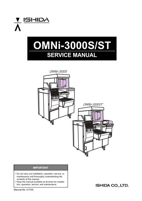
<strong>OMNi</strong>-<strong>3000S</strong>/<strong>ST</strong><br />
<strong>SERVICE</strong> <strong>MANUAL</strong><br />
<br />
<br />
IMPORTANT<br />
• Do not carry out installation, operation, service, or<br />
maintenance until thoroughly understanding the<br />
contents of this manual.<br />
• Keep this manual available at all times for installation,<br />
operation, service, and maintenance.<br />
Manual No. 0170A<br />
<strong>OMNi</strong>-<strong>3000S</strong>/<strong>ST</strong> Service Manual
© Ishida Co., Ltd. 2002<br />
All rights are reserved. No part of this publication may be reproduced, stored in a retrieval system, or transmitted, in any form,<br />
or by any means, mechanical, electronic, photocopying, recording, or otherwise, without prior written permission of Ishida.<br />
No patent liability is assumed with respect to the use of the information contained herein. Moreover, because Ishida is constantly<br />
striving to improve its high-quality products, the information contained in this manual is subject to change without notice. Every<br />
precaution has been taken in the preparation of this manual. Nevertheless, Ishida assumes no responsibility for errors or<br />
omissions. Neither is any liability assumed for damages resulting from the use of the information contained in this publication.<br />
<strong>OMNi</strong>-<strong>3000S</strong>/<strong>ST</strong> Service Manual
SAFETY CONSIDEATIONS<br />
This service manual contains information necessary for servicing the <strong>OMNi</strong>-<strong>3000S</strong>T. It is strongly advised<br />
that you read and clearly understand the contents of this manual before beginning any maintenance on<br />
this machine. The following safety measures must be observed to ensure the safe servicing of this<br />
machine:<br />
• Servicing is to be done by qualified service personnel only<br />
These service instructions are for use by qualified service personnel who fully understand the potenti<br />
hazards involved. To avoid any possible danger, do not perform any service procedures unless<br />
qualified to do so.<br />
• Perform only the specified service procedures<br />
To ensure personal safety, do not perform any service procedures that are not specifically mentioned<br />
in this manual.<br />
• Properly ground machinery<br />
As a Class 1 electrical device, this machine requires protective grounding for safe operation. To avoid<br />
any potential electrical shock, securely attach the protective ground wire to the main grounding<br />
provision.<br />
• Avoid servicing while power is being supplied<br />
Power supply to the machine is disconnected only when the electrical plug is removed from the electrical<br />
outlet. For protection against electrical shock, remove plug before performing any servicing to the<br />
machine. Machine servicing while power is being supplied and covers or enclosures are opened or<br />
removed should be avoided as much as possible. When servicing cannot be performed by any other<br />
means, service personnel should take precautions against the danger of electrical shock or other<br />
potential hazard involved.<br />
• Take precaution against residual electrical charge hazard<br />
Capacitors inside the machine may still hold an electrical charge even after power is disconnected.<br />
• Use same type fuses and components for replacement parts<br />
To avoid the potential hazards involved, do not replace fuses or components with types other than<br />
those specified in the parts list for this machine.<br />
MAINTENANCE PRECAUTIONS<br />
To insure the safety and long operating life of this machine, it is important to observe the following<br />
precautions:<br />
• Keep the area around the machine clear of any dust and debris<br />
• Do not leave screws or other foreign objects in the machine after performing routine<br />
maintenance since this can cause major damage to the machine when the electrical switch<br />
is turned on.<br />
• Always remove wires by holding the connector and pulling to disconnect.<br />
Do not disconnect by pulling on the wires themselves since this may cause a wire to snap or damage<br />
he connection.<br />
• Before disassembling or adjusting this machine, make sure you thoroughly understand<br />
and follow each step in the order indicated in this manual.<br />
i<br />
<strong>OMNi</strong>-<strong>3000S</strong>/<strong>ST</strong> Service Manual
CONTENTS<br />
Chapter 1<br />
<strong>OMNi</strong>-<strong>3000S</strong> OVERVIEW<br />
1.1 APPEARANCE ................................................................................................................. 1-2<br />
1.2 BASIC SPECIFICATIONS ................................................................................................ 1-3<br />
1.3 NAME OF EACH UNIT ...................................................................................................... 1-4<br />
1.4 NAME OF EACH MOTOR ................................................................................................ 1-5<br />
1.5 NAME OF EACH POWER SUPPLY ................................................................................ 1-6<br />
1.6 FUNCTION OF EACH UNIT ............................................................................................. 1-7<br />
1.7 <strong>ST</strong>ICKERS ....................................................................................................................... 1-9<br />
1.7.1 WARNING SYMBOLS .................................................................................................. 1-9<br />
1.7.2 <strong>ST</strong>ICKER DEFINITIONS ............................................................................................ 1-10<br />
1.7.3 <strong>ST</strong>ICKER PLACEMENT ............................................................................................. 1-11<br />
Chapter 2<br />
<strong>OMNi</strong>-<strong>3000S</strong>T OVERVIEW<br />
2.1 APPEARANCE ................................................................................................................. 2-2<br />
2.2 BASIC SPECIFICATIONS ................................................................................................ 2-3<br />
2.3 NAME OF EACH UNIT ...................................................................................................... 2-4<br />
2.4 NAME OF EACH MOTOR ................................................................................................ 2-5<br />
2.5 NAME OF EACH POWER SUPPLY ................................................................................ 2-6<br />
2.6 FUNCTION OF EACH UNIT ............................................................................................. 2-7<br />
2.7 <strong>ST</strong>ICKERS ....................................................................................................................... 2-9<br />
2.7.1 WARNING SYMBOLS .................................................................................................. 2-9<br />
2.7.2 <strong>ST</strong>ICKER DEFINITIONS ............................................................................................ 2-10<br />
2.7.3 <strong>ST</strong>ICKER PLACEMENT ............................................................................................. 2-11<br />
Chapter 3<br />
IN<strong>ST</strong>ALLATION<br />
3.1 IN<strong>ST</strong>ALLATION PRECAUTIONS ...................................................................................... 3-2<br />
3.1.1 NECESSARY TOOLS.................................................................................................. 3-2<br />
3.1.2 PROHIBITED LOCATIONS .......................................................................................... 3-2<br />
3.1.3 POWER SUPPLY......................................................................................................... 3-2<br />
3.1.4 PACKING MATERIALS ................................................................................................ 3-3<br />
3.1.5 WORK CLOTHES........................................................................................................ 3-3<br />
3.2 LEVEL ADJU<strong>ST</strong>MENT ...................................................................................................... 3-4<br />
3.3 IN<strong>ST</strong>ALLATION SPACE .................................................................................................... 3-5<br />
3.4 SAFETY SWITCH ............................................................................................................ 3-6<br />
3.5 CABLE CONNECTION .................................................................................................... 3-7<br />
3.6 MAIN POWER ON/OFF ................................................................................................... 3-8<br />
3.6.1 POWER ON ................................................................................................................. 3-8<br />
3.6.2 POWER OFF ............................................................................................................... 3-8<br />
3.6.3 EMERGENCY <strong>ST</strong>OP BUTTON .................................................................................... 3-8<br />
3.7 MEMORY INITIALZATION ................................................................................................. 3-9<br />
3.8 LABEL SETTING ............................................................................................................ 3-11<br />
<strong>OMNi</strong>-<strong>3000S</strong>/<strong>ST</strong> Service Manual<br />
ii
3.9 FILM ROLL SETTING ..................................................................................................... 3-12<br />
3.9.1 FILM SETTING .......................................................................................................... 3-13<br />
3.9.2 FILM POSITION ADJU<strong>ST</strong>MENT ................................................................................. 3-14<br />
3.9.3 BRAKE UNIT ADJU<strong>ST</strong>MENT ..................................................................................... 3-15<br />
3.10 HEATER SWITCH .......................................................................................................... 3-16<br />
Chapter 4<br />
TE<strong>ST</strong> MODE<br />
4.1 HARDWARE TE<strong>ST</strong> .......................................................................................................... 4-2<br />
4.1.1 KEY CHECK ................................................................................................................. 4-3<br />
4.1.2 COMMUNICATION CHECK .......................................................................................... 4-7<br />
4.1.3 A/D CHECK .................................................................................................................. 4-8<br />
4.1.4 THERMAL HEAD SET ................................................................................................. 4-9<br />
4.1.5 PROGRAM NUMBER ................................................................................................ 4-11<br />
4.2 MEMORY INITIALIZATION .............................................................................................. 4-12<br />
4.2.1 RAM DISK ALL CLEAR PROCESS ........................................................................... 4-12<br />
4.2.2 E2PROM INITIALIZE PROCESS................................................................................ 4-12<br />
4.2.3 TE<strong>ST</strong> DATA SETTING PROCESS ............................................................................ 4-13<br />
4.3 PERIPHERAL MACHINE ................................................................................................ 4-14<br />
4.3.1 WRAPPER CHECK ................................................................................................... 4-15<br />
4.3.2 WRAPPER SETTING ................................................................................................ 4-16<br />
4.3.3 PRINTER ADJU<strong>ST</strong>MENT ........................................................................................... 4-18<br />
4.4 FILE CONTROL ............................................................................................................. 4-21<br />
4.4.1 FILE CHECK .............................................................................................................. 4-22<br />
4.4.2 DATA SAVE / LOAD .................................................................................................. 4-23<br />
4.5 ROM SWITCH SETTING ............................................................................................... 4-26<br />
4.5.1 ROM SWITCH SETTING 1/2 ..................................................................................... 4-26<br />
4.5.2 ROM SWITCH SETTING 2/2 ..................................................................................... 4-29<br />
Chater 5<br />
SETUP MODE<br />
5.1 LABEL FORMAT .............................................................................................................. 5-2<br />
5.2 BARCODE SETUP .......................................................................................................... 5-5<br />
5.3 CODE SETUP ................................................................................................................. 5-7<br />
5.4 INITIAL DATA SET ............................................................................................................ 5-8<br />
5.5 PRINT SELECTION ....................................................................................................... 5-11<br />
5.6 AUTO RENEW SET....................................................................................................... 5-12<br />
5.7 TOTAL SELECT ............................................................................................................. 5-13<br />
5.8 FUNCTION KEY SET ..................................................................................................... 5-14<br />
5.9 PASSWORD SETTING.................................................................................................. 5-16<br />
5.10 LABEL FORMAT EDIT ................................................................................................... 5-17<br />
5.10.1 FORMAT CHANGE .................................................................................................... 5-17<br />
5.10.2 LABEL FORMAT HEADER EDIT ............................................................................... 5-19<br />
5.10.3 FORMAT EDIT FOR EACH UNIT .............................................................................. 5-20<br />
5.11 WRAPPER SETTING .................................................................................................... 5-41<br />
5.12 LABEL POSITION ADU<strong>ST</strong>MENT ................................................................................... 5-45<br />
iii<br />
<strong>OMNi</strong>-<strong>3000S</strong>/<strong>ST</strong> Service Manual
Chapter 6<br />
PROGRAM MODE<br />
6.1 PLU FILE .......................................................................................................................... 6-2<br />
6.1.1 PLU FILE SCREEN 1/3................................................................................................ 6-2<br />
6.1.2 PLU FILE SCREEN 2/3................................................................................................ 6-5<br />
6.1.3 PLU FILE SCREEN 2/3................................................................................................ 6-6<br />
6.1.4 PLU FILE SCREEN 3/3................................................................................................ 6-8<br />
6.2 COMMODITY NAME....................................................................................................... 6-10<br />
6.2.1 COMMODITY NAME EDIT SCREEN ......................................................................... 6-10<br />
6.2.2 SAVE CONFIRMATION POP-UP SCREEN................................................................ 6-14<br />
6.2.3 DELETION CONFIRMATION POP-UP SCREEN ....................................................... 6-15<br />
6.2.4 COPY EXECUTION CONFIRMATION POP-UP SCREEN.......................................... 6-16<br />
6.2.5 EDITOR SPECIFICATION .......................................................................................... 6-17<br />
6.3 PRICE CHANGE ............................................................................................................ 6-18<br />
6.3.1 PRICE CHANGE EDIT SCREEN................................................................................ 6-18<br />
6.3.2 PRICE CHANGE (REAL) EDIT SCREEN .................................................................. 6-19<br />
6.3.3 PRICE CHANGE (BATCH) EDIT SCREEN ................................................................ 6-20<br />
6.4 EXTRA MESSAGE ......................................................................................................... 6-21<br />
6.4.1 EXTRA MESSAGE EDIT SCREEN ............................................................................ 6-21<br />
6.4.2 SAVE CONFIRMATION POP-UP SCREEN................................................................ 6-22<br />
6.4.3 DELETE CONFIRMATION POP-UP SCREEN ........................................................... 6-23<br />
6.4.4 COPY CONFIRMATION POP-UP SCREEN .............................................................. 6-24<br />
6.5 DATE/TIME REGI<strong>ST</strong>RATION ......................................................................................... 6-25<br />
6.6 <strong>ST</strong>ORE NAME/ADDRESS ............................................................................................. 6-26<br />
6.6.1 <strong>ST</strong>ORE FILE EDIT SCREEN ..................................................................................... 6-26<br />
6.6.2 <strong>ST</strong>ORE FILE DELETE CONFIRMATION POP-UP SCREEN ..................................... 6-27<br />
6.6.3 <strong>ST</strong>ORE NAME EDIT SCREEN ................................................................................... 6-28<br />
6.6.4 <strong>ST</strong>ORE NAME SAVE CONFIRMATION POP-UP SCREEN ....................................... 6-29<br />
6.6.5 <strong>ST</strong>ORE NAME DELETE CONFIRMATION POP-UP SCREEN .................................. 6-30<br />
6.6.6 <strong>ST</strong>ORE NAME COPY CONFIRMATION POP-UP SCREEN ...................................... 6-31<br />
6.6.7 <strong>ST</strong>ORE ADDRESS EDIT SCREEN ........................................................................... 6-32<br />
6.6.8 <strong>ST</strong>ORE ADDRESS SAVE CONFIRMATION POP-UP SCREEN ................................ 6-33<br />
6.6.9 <strong>ST</strong>ORE ADDRESS DELETE CONFIRMATION POP-UP SCREEN ........................... 6-34<br />
6.6.10 <strong>ST</strong>ORE ADDRESS COPY CONFIRMATION POP-UP SCREEN ............................... 6-35<br />
6.7 PRESET ........................................................................................................................ 6-36<br />
6.7.1 PRESET FILE EDIT SCREEN ................................................................................... 6-36<br />
6.7.2 DELETE CONFIRMATION POP-UP SCREEN ........................................................... 6-37<br />
6.8 BARCODE CHECK LABEL ........................................................................................... 6-38<br />
6.9 DEPARTMENT NAME .................................................................................................... 6-39<br />
6.9.1 DEPARTMENT NAME EDIT SCREEN ....................................................................... 6-39<br />
6.9.2 SAVE CONFIRMATION POP-UP SCREEN................................................................ 6-40<br />
6.9.3 DELETE CONFIRMATION POP-UP SCREEN ........................................................... 6-41<br />
6.9.4 COPY CONFIRMATION POP-UP SCREEN .............................................................. 6-42<br />
6.10 GROUP NAME ............................................................................................................... 6-43<br />
6.10.1 GROUP NAME EDIT SCREEN .................................................................................. 6-43<br />
6.10.2 SAVE CONFIRMATION POP-UP SCREEN................................................................ 6-44<br />
6.10.3 DELETE CONFIRMATION POP-UP SCREEN ........................................................... 6-45<br />
6.10.4 COPY CONFIRMATION POP-UP SCREEN .............................................................. 6-46<br />
6.11 TRAY FILE ...................................................................................................................... 6-47<br />
6.11.1 TRAY PROGRAM 1/2 SCREEN ................................................................................ 6-47<br />
6.11.2 TRAY PROGRAM 2/2 SCREEN ................................................................................ 6-49<br />
6.11.3 TRAY PROGRAM 1/2 DELETE CONFIRMATION POP-UP SCREEN ....................... 6-50<br />
<strong>OMNi</strong>-<strong>3000S</strong>/<strong>ST</strong> Service Manual<br />
iv
6.11.4 TRAY NAME EDIT SCREEN ...................................................................................... 6-51<br />
6.11.5 RAY NAME SAVE CONFIRMATION POP-UP SCREEN ............................................. 6-52<br />
6.11.6 TRAY NAME DELETE CONFIRMATION POP-UP SCREEN ..................................... 6-53<br />
6.11.7 TRAY NAME COPY CONFIRMATION POP-UP SCREEN ......................................... 6-54<br />
6.12 CAMPAIGN ITEM ............................................................................................................ 6-55<br />
6.12.1 CAMPAIGN ITEM 1/2 EDIT SCREEN ........................................................................ 6-55<br />
6.12.2 CAMPAIGN ITEM 1/2 DELETE CONFIRMATION POP-UP SCREEN ........................ 6-56<br />
6.12.3 CAMPAIGN ITEM 2/2 EDIT SCREEN ........................................................................ 6-57<br />
6.12.4 CAMPAIGN ITEM 2/2 DELETE CONFIRMATION POP-UP SCREEN ........................ 6-58<br />
6.13 CASSETTE NUMBER .................................................................................................... 6-59<br />
6.14 MACHINE SETUP .......................................................................................................... 6-60<br />
6.15 ONLINE SETUP ............................................................................................................. 6-61<br />
6.16 FILE DOWNLOAD ......................................................................................................... 6-62<br />
6.17 NUTRITION .................................................................................................................... 6-63<br />
Chapter 7 MAIN UNITS & ERROR MESSAGES<br />
7.1 CONTROL CONSOLE .................................................................................................... 7-2<br />
7.2 PRINTER / APPLICATOR ................................................................................................ 7-4<br />
7.3 REAR CHANGE MOTOR ................................................................................................. 7-7<br />
7.4 LEFT / RIGHT CHANGE MOTOR .................................................................................... 7-9<br />
7.5 PUSHER ........................................................................................................................ 7-11<br />
7.6 FEEDER MOVEMENT ................................................................................................... 7-13<br />
7.7 FEEDER DRIVE ............................................................................................................ 7-15<br />
7.8 INFEED CONVEYOR..................................................................................................... 7-17<br />
7.9 SET ROLLER ................................................................................................................ 7-19<br />
7.10 SWITCHING LIFT ........................................................................................................... 7-21<br />
7.11 LABELING MACHINE MOVEMENT ................................................................................ 7-23<br />
7.12 FILM ROLLER ................................................................................................................ 7-25<br />
7.13 CUTTER ........................................................................................................................ 7-27<br />
7.14 LIFT SERVO CONTROLLER ........................................................................................ 7-29<br />
7.15 FILM FEEDER................................................................................................................ 7-31<br />
7.16 BOARD(P-857, P-858A, P-858B, P-858C) .................................................................... 7-33<br />
7.17 EMERGENCY <strong>ST</strong>OP BUTTON...................................................................................... 7-39<br />
7.18 FOREIGN OBJECT / ITEM SENSOR ............................................................................ 7-41<br />
7.19 SOLENOID..................................................................................................................... 7-43<br />
7.20 FILM TENSION CONTROL DIAL ................................................................................... 7-45<br />
7.21 LIFT ................................................................................................................................ 7-47<br />
7.22 SAFETY SWITCH .......................................................................................................... 7-49<br />
7.23 LIFT DRIVE .................................................................................................................... 7-51<br />
7.24 LIFT HEAD ..................................................................................................................... 7-53<br />
7.25 FUSE MAX. CAPACITY .................................................................................................. 7-54<br />
7.26 DISCHAGE CONVEYOR ............................................................................................... 7-55<br />
v<br />
<strong>OMNi</strong>-<strong>3000S</strong>/<strong>ST</strong> Service Manual
Chapter 8<br />
LOAD CELL UNIT<br />
8.1 LOCATION OF MAIN PARTS ........................................................................................... 8-2<br />
8.2 REPLACING THE LOAD CELL UNIT ............................................................................... 8-3<br />
8.3 SPAN ADJU<strong>ST</strong>MENT ....................................................................................................... 8-6<br />
8.3.1 ADJU<strong>ST</strong>MENT PROCEDURE ...................................................................................... 8-6<br />
8.3.2 SPAN ADJU<strong>ST</strong>MENT FLOWCHART ........................................................................... 8-7<br />
Chapter 9<br />
WRAPPING KNOWLEDGE<br />
9.1 WRAPPING PROGRAMMING .......................................................................................... 9-2<br />
Chapter 10 WIRING DIAGRAMS .............................................................................................. 10-1<br />
<strong>OMNi</strong>-<strong>3000S</strong>/<strong>ST</strong> Service Manual<br />
vi
Chapter 1 <strong>OMNi</strong>-<strong>3000S</strong> OVERVIEW<br />
Chapter 1<br />
<strong>OMNi</strong>-<strong>3000S</strong> OVERVIEW<br />
1-1 <strong>OMNi</strong>-<strong>3000S</strong>/<strong>ST</strong> Service Manual
Chapter 1 <strong>OMNi</strong>-<strong>3000S</strong> OVERVIEW<br />
1.1 APPEARANCE<br />
<strong>OMNi</strong>-<strong>3000S</strong>/<strong>ST</strong> Service Manual 1-2
Chapter 1 <strong>OMNi</strong>-<strong>3000S</strong> OVERVIEW<br />
1.2 BASIC SPECIFICATIONS<br />
Scale<br />
Printer<br />
Control Console<br />
Wrapper<br />
Power supply<br />
<strong>Weighing</strong> capacity 30lb<br />
Wrapping capacity 15lb<br />
Accuracy 1/3000<br />
Minimum graduation 0.01 lb. (Single range)<br />
Thermal head<br />
60mm, 7.4 dot/mm<br />
Printing speed 85mm/sec.<br />
Printing size<br />
Auto: 64mm (W) × 85mm (H)<br />
Manual : 64mm (W) × 120mm (H)<br />
Font style<br />
Reverse, Bold, Bold Reverse, Underline, Ruled Line<br />
Display method 9.4 inch analog touch panel<br />
Preset keys<br />
72 × 2 keys<br />
Function keys<br />
48 keys<br />
Number of programs Up to approx. 3000<br />
(when production total is not performed)<br />
Wrapping speed Max. 30 packs/min. (190 × 100mm tray)<br />
Wrapping size 130 to 410mm (W) : 5.1 to 16.1 inch<br />
130 to 260mm (D) : 5.1 to 10.2 inch<br />
20 to 150mm (H) : 0.8 to 5.9 inch<br />
Film size<br />
350 to 610mm: 13.8 to 24.0 inch<br />
Film material<br />
Poly orephine / vinyl chloride<br />
3-phase 208 (220/240) VAC, 60Hz<br />
Note 1: Wrapping conditions listed in the above specifications may differ depending on tray shape or weight.<br />
2: Specifications are subject to change without prior notice.<br />
<strong>OMNi</strong>-<strong>3000S</strong><br />
S: Rotating applicator<br />
1-3 <strong>OMNi</strong>-<strong>3000S</strong>/<strong>ST</strong> Service Manual
Chapter 1 <strong>OMNi</strong>-<strong>3000S</strong> OVERVIEW<br />
1.3 NAME OF EACH UNIT<br />
<strong>OMNi</strong>-<strong>3000S</strong>/<strong>ST</strong> Service Manual 1-4
Chapter 1 <strong>OMNi</strong>-<strong>3000S</strong> OVERVIEW<br />
1.4 NAME OF EACH MOTOR<br />
1-5 <strong>OMNi</strong>-<strong>3000S</strong>/<strong>ST</strong> Service Manual
Chapter 1 <strong>OMNi</strong>-<strong>3000S</strong> OVERVIEW<br />
1.5 NAME OF EACH POWER SUPPLY<br />
<strong>OMNi</strong>-<strong>3000S</strong>/<strong>ST</strong> Service Manual 1-6
Chapter 1 <strong>OMNi</strong>-<strong>3000S</strong> OVERVIEW<br />
1.6 FUNCTION OF EACH UNIT<br />
Infeed Conveyor<br />
Scale<br />
Lift Drive<br />
Lift Heads<br />
Lift Switch<br />
Rear Wrapping Plates<br />
Left/Right Wrapping<br />
Plates<br />
Pusher<br />
Feeder Drive<br />
Feeder Mover<br />
Film Feeder<br />
Set Roller<br />
- Transports the tray to the lift heads.<br />
- Contains the scale and is driven by the stepping motor after the tray is weighed.<br />
The motor drives a chain containing four claws which push the tray. The<br />
chain stops when it passes the reference position sensor.<br />
- Weighs a maximum capacity of up to 30lb<br />
0.01lb (from 15lb up to 30lb).<br />
- Lifts the tray vertically up to the wrapper unit.<br />
- The servo controller receives the activating signal and is started by the controller.<br />
The lift drive utilizes two different movements: “Up/down for wrapping”<br />
and “Up/down for switching between large and small lift”.<br />
- Transports trays and tilt to facilitate the wrapping action.<br />
- There are 10 heads, out of which three sliding heads are used depending on<br />
the tray size.<br />
- Moves the lever to the appropriate size using a servo motor.<br />
- Switches the lift heads from “large to small” and “small to large”.<br />
- Wraps the film underneath the rear of the tray.<br />
- The motor starts with the wrapping start timing.<br />
- The wrapping plate moves forward and pushes the film underneath the rear<br />
of the tray.<br />
- Wraps the film over the sides of the tray.<br />
- The motor starts with the wrapping start timing.<br />
- The left and right wrapping plates slide in and fold the film underneath the<br />
tray.<br />
- Wraps the film under the front of the tray and pushes the tray out.<br />
- The motor starts with the wrapping start timing.<br />
- The pusher comes forward, folding the film underneath the tray in time with<br />
the feeder clamp.<br />
- Drives the feed belt, feed roller and cutter.<br />
- When the motor moves, the front and back feeders turn the number of times<br />
specified by the encoder. The feed roller and cutter switch on and off using a<br />
clutch and brake.<br />
- Moves the rear feeder depending on the size of the film using a motor.<br />
- For 2 and 3 roll types, the sensors detect the width of each film and moves to<br />
the film width.<br />
- For the 1 roll type, the feeder mover moves to the where the sensor detects<br />
the end of the film.<br />
- Feeds and grips the film during wrapping.<br />
- Feeds the film using the count photo sensor according to the programmed<br />
tray length. It also grips the film with the side and center clamps to stretch the<br />
film during wrapping.<br />
- Sets the film into the film feeder.<br />
- To set the film, lift the set roller, place the film onto the set roller with both<br />
hands so that it sticks to the feeder belt, and close the set roller.<br />
- Film Grip: Holds the film already set onto the feed belt when in standby.<br />
- Film Up/down: Raises the end of the film off the feed belt after it has been<br />
gripped.<br />
- Cut-off belt: Cuts the film along the perforated line.<br />
- Cuts off the film from the feeder belt, and keeps it away from the belt during<br />
film centering.<br />
1-7 <strong>OMNi</strong>-<strong>3000S</strong>/<strong>ST</strong> Service Manual
Chapter 1 <strong>OMNi</strong>-<strong>3000S</strong> OVERVIEW<br />
Feeder Roller<br />
Cutter<br />
Film Holder<br />
Heater<br />
Printer<br />
Label Applicator<br />
Label Applicator<br />
Mover<br />
Control Console<br />
Power Supply Unit<br />
Film Roll Unit<br />
- Joined via a clutch to the feeder drive, this roller sends the film to the feeder<br />
belt. It’s stopped by a brake.<br />
- The cutter makes a perforation in the film for the appropriate size.<br />
- It is stopped by the brake.<br />
- Sets the appropriate film.<br />
- In the 2 roll model, film can be set on the left and right hand sides.<br />
- For the 1 roll model, film can be set on the right.<br />
- Seals the film underneath the tray after it is wrapped.<br />
- The heater is used at approximately 120°C. Special caution needs to betaken<br />
with the temperature setting for polyethylene films.<br />
- Prints out labels (Auto: 60 (W) × 85mm (H), Manual: 60 (W) × 120mm (H)) in<br />
the format chosen.<br />
- Holds labels using a suction plate, and applies the label to trays in accordance<br />
with the applicator timing signal. The amount of movement of the arm<br />
can be adjusted to fit the volume in trays.<br />
- Adjusts the label position depending on the length of the tray.<br />
- It moves left and right to the position (1 to 12) programmed for that tray.<br />
- Operation panel (stroke key) contains numbers, units, fixed price, call print,<br />
tare, and delete keys. The box contains the boards (P-850 and P-851)<br />
- It has a connection to the scale, wrapper, and printer etc.<br />
- The LCD (touch panel) is used for display and data entry at the normal screen,<br />
setting mode, program mode, total mode, subtraction mode, etc.<br />
- Contains the power supply and boards (P-857, P-858A, P-858B, P-858C)<br />
- P-857 : Wrapper CPU board (ROM)<br />
- P-858A : Driver board<br />
- P-858B : Driver board (mainly right hand)<br />
- P-858C : Driver board (mainly left hand)<br />
- 24V power supply<br />
- Stepping driver (ROM)<br />
- Electromagnetic Contacter : Thermal Relay<br />
- Helps film feeding actively by driving film roll.<br />
- The film roll drive is synchronized with feeder drive.<br />
<strong>OMNi</strong>-<strong>3000S</strong>/<strong>ST</strong> Service Manual 1-8
Chapter 1 <strong>OMNi</strong>-<strong>3000S</strong> OVERVIEW<br />
1.7 <strong>ST</strong>ICKERS<br />
1.7.1 WARNING SYMBOLS<br />
This machine is manufactured for use according to proper procedures by qualified service personnel and<br />
only for the purposes described in this manual.<br />
The warning symbols in this manual and warning stickers affixed to the machine itself are divided into<br />
three categories, depending on the level of danger, or seriousness of potential injury. The definition of<br />
each of these warnings and precautions is shown below. Failure to heed these warnings and precautions<br />
may result in bodily injury or damage to the machine.<br />
<br />
<br />
<br />
Indicates information that, if not heeded, is likely to result in loss of life or<br />
serious injury.<br />
Indicates information that, if not heeded, could possibly result in loss of life or<br />
serious injury.<br />
Indicates information that, if not heeded, could result in relatively serious or<br />
minor injury, damage to the machine, or faulty operation.<br />
1-9 <strong>OMNi</strong>-<strong>3000S</strong>/<strong>ST</strong> Service Manual
Chapter 1 <strong>OMNi</strong>-<strong>3000S</strong> OVERVIEW<br />
1.7.2 <strong>ST</strong>ICKER DEFINITIONS<br />
Warning stickers are affixed to the machine to warn operators of possible dangers.<br />
CAUTION<br />
DISSONNECT POWER BEFORE SERVICING INSIDE<br />
NO OPERATOR <strong>SERVICE</strong> AREA INSIDE<br />
This sticker indicates that the main power should<br />
be disconnected when performing any type of internal<br />
maintenance or service on the machine.<br />
CAUTION<br />
HOT SURFACE Keep hands away<br />
This sticker indicates that hands should be kept<br />
away from hot surfaces.<br />
CAUTION<br />
HOT SURFACE Keep hands away<br />
This sticker indicates that the emergency stop button<br />
should always be pressed before servicing the<br />
machine internally.<br />
WARNING<br />
The lift comes down even an<br />
emergency switch is pressed.<br />
Please pull out the conveyor<br />
for the cleaning.<br />
This sticker indicates that there is a danger hands<br />
may get caught when the lift comes down, even<br />
after the emergency switch has been pressed.<br />
101b<br />
CAUTION<br />
MAXIMUM LOAD<br />
AT FULL EXTENSION<br />
WARNING<br />
Keep hands<br />
away from<br />
cutting parts.<br />
This sticker indicates that the maximum load at full<br />
extension should not exceed 10 lbs on the infeed<br />
conveyor cover.<br />
This sticker is placed on parts where there is a<br />
danger of the operator being cut by a cutting<br />
mechanism such as the cutter. Always press the<br />
emergency stop button before starting work near<br />
any cutting mechanism.<br />
This sticker indicates that there is a danger of electric<br />
shock on the power supply unit cover.<br />
<strong>OMNi</strong>-<strong>3000S</strong>/<strong>ST</strong> Service Manual 1-10
Chapter 1 <strong>OMNi</strong>-<strong>3000S</strong> OVERVIEW<br />
1.7.3 <strong>ST</strong>ICKER PLACEMENT<br />
<br />
<br />
<br />
<br />
<br />
<br />
<br />
<br />
<br />
<br />
<br />
<br />
<br />
<br />
<br />
<br />
<br />
<br />
<br />
<br />
<br />
<br />
<br />
<br />
<br />
<br />
<br />
<br />
<br />
<br />
<br />
<br />
<br />
<br />
1-11 <strong>OMNi</strong>-<strong>3000S</strong>/<strong>ST</strong> Service Manual
Chapter 2 <strong>OMNi</strong>-<strong>3000S</strong>T OVERVIEW<br />
Chapter 2<br />
<strong>OMNi</strong>-<strong>3000S</strong>T OVERVIEW<br />
2-1 <strong>OMNi</strong>-<strong>3000S</strong>/<strong>ST</strong> Service Manual
Chapter 2 <strong>OMNi</strong>-<strong>3000S</strong>T OVERVIEW<br />
2.1 APPEARANCE<br />
Touch panel<br />
Label printer<br />
Label outlet<br />
Discharge conveyor<br />
Safety conver<br />
Heater conveyor<br />
Side cover<br />
Keysheet<br />
Infeed conveyor<br />
B<br />
A<br />
Side door<br />
<strong>Weighing</strong> mechanism<br />
(Internal)<br />
Film loading door<br />
Level adjustment foot<br />
Film loading door<br />
Front cover<br />
Caster<br />
<strong>OMNi</strong>-<strong>3000S</strong>/<strong>ST</strong> Service Manual 2-2
Chapter 2 <strong>OMNi</strong>-<strong>3000S</strong>T OVERVIEW<br />
2.2 BASIC SPECIFICATIONS<br />
Scale<br />
Printer<br />
Control console<br />
Wrapper<br />
Power supply<br />
Auto discharge<br />
conveyor<br />
<strong>Weighing</strong> capacity 30 lb.<br />
Wrapping capacity 15 lb.<br />
Accuracy 1/3000<br />
Minimum graduation 0.01 lb. (Single range)<br />
Thermal head<br />
60 mm, 7.4 dot/mm<br />
Printing speed 85 mm/sec.<br />
Printing size<br />
Auto: 64 mm (W) × 85 mm (H)<br />
Manual: 64 mm (W) × 120 mm (H)<br />
Font style<br />
Reverse, Bold, Bold Reverse, Underline, Ruled line<br />
Display method 9.4 inch analog touch panel<br />
Preset keys<br />
72 × 2 keys<br />
Function keys<br />
48 keys<br />
Number of programs Up to approx. 3000<br />
(when production total is not performed)<br />
Wrapping speed Max. 30 packs/min. (190 × 100mm tray)<br />
Wrapping size 130 to 410 mm (W) : 5.1 to 16.1 inch<br />
130 to 260 mm (D) : 5.1 to 10.2 inch<br />
20 to 150 mm (H) : 0.8 to 5.9 inch<br />
Film size<br />
350 to 610 mm: 13.8 to 24.0 inch<br />
Film materia<br />
Poly orephine / vinyl chloride<br />
3-phase 208 (220/240) VAC, 60Hz<br />
Discharge conveyor Available<br />
Heater conveyor Available<br />
Note 1: Wrapping conditions listed in the above specifications may differ depending on tray shape or weight.<br />
2: Specifications are subject to change without prior notice.<br />
S: Rotating applicator<br />
<strong>OMNi</strong>-<strong>3000S</strong>T<br />
T: Discharge conveyor<br />
2-3 <strong>OMNi</strong>-<strong>3000S</strong>/<strong>ST</strong> Service Manual
Chapter 2 <strong>OMNi</strong>-<strong>3000S</strong>T OVERVIEW<br />
2.3 NAME OF EACH UNIT<br />
Wrapper<br />
Rear folder<br />
Left/right folder<br />
pusher<br />
Touch panel<br />
Tray holder<br />
Film feeder<br />
Tray stopper<br />
Lift head<br />
Infeed conveyor<br />
Lift switch<br />
Scale<br />
Shaft<br />
Labeling machine movement<br />
Printer cover<br />
Touch panel<br />
Printer/Applicator<br />
Set roller<br />
Cutter<br />
Control console<br />
Feeding roller<br />
Discharge conveyor<br />
Heater conveyor<br />
<strong>OMNi</strong>-<strong>3000S</strong>/<strong>ST</strong> Service Manual 2-4
Chapter 2 <strong>OMNi</strong>-<strong>3000S</strong>T OVERVIEW<br />
2.4 NAME OF EACH MOTOR<br />
Heater conveyor motor<br />
Discharge conveyor motor<br />
Labeling machine move motor<br />
Left/right side<br />
wrapping motor<br />
Rear side<br />
Wrapping motor<br />
Pusher motor (DC)<br />
Feeder move motor<br />
Infeed conveyor<br />
(Stepping motor)<br />
Feeder motor<br />
Lift drive<br />
(Servo motor)<br />
Film roll move motor<br />
Lift switch motor<br />
Labeling machine solenoid<br />
Film grab<br />
Up/down<br />
Roller clutch/brake<br />
Cutout solenoid<br />
Side clamp solenoid<br />
Cutter clutch/brake<br />
Film brake solenoid (L)<br />
Labeling anglec (Stepping motor)<br />
Label adsorberc(Fan)<br />
Label feederc(Stepping)<br />
Arm drivec(Servo motor)<br />
Film grab<br />
Up/down<br />
Roller clutch/brake<br />
Cutout solenoid<br />
Heater conveyor motor<br />
Cutter clutch/brake<br />
Discharge conveyor motor<br />
Center clamp solenoid<br />
Film brake solenoid (R)<br />
2-5 <strong>OMNi</strong>-<strong>3000S</strong>/<strong>ST</strong> Service Manual
Chapter 2 <strong>OMNi</strong>-<strong>3000S</strong>T OVERVIEW<br />
2.5 NAME OF EACH POWER SUPPLY<br />
P-857<br />
P-858A(A)<br />
P-858A(C)<br />
Electro magnetic contactor<br />
Transformer 3-phase<br />
[AC 208 (220/240) V]<br />
Servo controller<br />
P-852<br />
Power supply<br />
P-901<br />
Supplementary<br />
protector<br />
Transformer (to AC 100V)<br />
Relay<br />
P-850<br />
P-851<br />
Power supply<br />
Power supply<br />
Fuse holder<br />
Thermal relay<br />
P-858A(B)<br />
P-858A(C)<br />
P-858A(A)<br />
P-857<br />
Machine operation enable<br />
(Cycle Start)<br />
<strong>OMNi</strong>-<strong>3000S</strong>/<strong>ST</strong> Service Manual 2-6
Chapter 2 <strong>OMNi</strong>-<strong>3000S</strong>T OVERVIEW<br />
2.6 FUNCTION OF EACH UNIT<br />
Infeed Conveyor<br />
Scale<br />
Lift Drive<br />
Lift Heads<br />
Lift Switch<br />
Rear Wrapping Plates<br />
Left/Right Wrapping<br />
Plates<br />
Pusher<br />
Feeder Drive<br />
Feeder Mover<br />
Film Feeder<br />
Set Roller<br />
- Transports the tray to the lift heads.<br />
- Contains the scale and is driven by the stepping motor after the tray is weighed.<br />
The motor drives a chain containing four claws which push the tray. The<br />
chain stops when it passes the reference position sensor.<br />
- Weighs a maximum capacity of up to 30lb<br />
0.01lb (from 15lb up to 30lb).<br />
- Lifts the tray vertically up to the wrapper unit.<br />
- The servo controller receives the activating signal and is started by the controller.<br />
The lift drive utilizes two different movements: “Up/down for wrapping”<br />
and “Up/down for switching between large and small lift”.<br />
- Transports trays and tilt to facilitate the wrapping action.<br />
- There are 10 heads, out of which three sliding heads are used depending on<br />
the tray size.<br />
- Moves the lever to the appropriate size using a servo motor.<br />
- Switches the lift heads from “large to small” and “small to large”.<br />
- Wraps the film underneath the rear of the tray.<br />
- The motor starts with the wrapping start timing.<br />
- The wrapping plate moves forward and pushes the film underneath the rear<br />
of the tray.<br />
- Wraps the film over the sides of the tray.<br />
- The motor starts with the wrapping start timing.<br />
- The left and right wrapping plates slide in and fold the film underneath the<br />
tray.<br />
- Wraps the film under the front of the tray and pushes the tray out.<br />
- The motor starts with the wrapping start timing.<br />
- The pusher comes forward, folding the film underneath the tray in time with<br />
the feeder clamp.<br />
- Drives the feed belt, feed roller and cutter.<br />
- When the motor moves, the front and back feeders turn the number of times<br />
specified by the encoder. The feed roller and cutter switch on and off using a<br />
clutch and brake.<br />
- Moves the rear feeder depending on the size of the film using a motor.<br />
- For 2 and 3 roll types, the sensors detect the width of each film and moves to<br />
the film width.<br />
- For the 1 roll type, the feeder mover moves to the where the sensor detects<br />
the end of the film.<br />
- Feeds and grips the film during wrapping.<br />
- Feeds the film using the count photo sensor according to the programmed<br />
tray length. It also grips the film with the side and center clamps to stretch the<br />
film during wrapping.<br />
- Sets the film into the film feeder.<br />
- To set the film, lift the set roller, place the film onto the set roller with both<br />
hands so that it sticks to the feeder belt, and close the set roller.<br />
- Film Grip: Holds the film already set onto the feed belt when in standby.<br />
- Film Up/down: Raises the end of the film off the feed belt after it has been<br />
gripped.<br />
- Cut-off belt: Cuts the film along the perforated line.<br />
- Cuts off the film from the feeder belt, and keeps it away from the belt during<br />
film centering.<br />
2-7 <strong>OMNi</strong>-<strong>3000S</strong>/<strong>ST</strong> Service Manual
Chapter 2 <strong>OMNi</strong>-<strong>3000S</strong>T OVERVIEW<br />
Feeder Roller<br />
Cutter<br />
Film Holder<br />
Heater<br />
Printer<br />
Label Applicator<br />
Label Applicator<br />
Mover<br />
Control Console<br />
Power Supply Unit<br />
Film Roll Unit<br />
Discharge<br />
Conveyor<br />
- Joined via a clutch to the feeder drive, this roller sends the film to the feeder<br />
belt. It’s stopped by a brake.<br />
- The cutter makes a perforation in the film for the appropriate size.<br />
- It is stopped by the brake.<br />
- Sets the appropriate film.<br />
- In the 2 roll model, film can be set on the left and right hand sides.<br />
- For the 1 roll model, film can be set on the right.<br />
- Seals the film underneath the tray after it is wrapped.<br />
- The heater is used at approximately 120°C. Special caution needs to betaken<br />
with the temperature setting for polyethylene films.<br />
- Prints out labels (Auto: 60 (W) × 85mm (H), Manual: 60 (W) × 120mm (H)) in<br />
the format chosen.<br />
- Holds labels using a suction plate, and applies the label to trays in accordance<br />
with the applicator timing signal. The amount of movement of the arm<br />
can be adjusted to fit the volume in trays.<br />
- Adjusts the label position depending on the length of the tray.<br />
- It moves left and right to the position (1 to 12) programmed for that tray.<br />
- Operation panel (stroke key) contains numbers, units, fixed price, call print,<br />
tare, and delete keys. The box contains the boards (P-850 and P-851)<br />
- It has a connection to the scale, wrapper, and printer etc.<br />
- The LCD (touch panel) is used for display and data entry at the normal screen,<br />
setting mode, program mode, total mode, subtraction mode, etc.<br />
- Contains the power supply and boards (P-857, P-858A, P-858B, P-858C)<br />
- P-857 : Wrapper CPU board (ROM)<br />
- P-858A : Driver board<br />
- P-858B : Driver board (mainly right hand)<br />
- P-858C : Driver board (mainly left hand)<br />
- 24V power supply<br />
- Stepping driver (ROM)<br />
- Electromagnetic Contacter : Thermal Relay<br />
- Helps film feeding actively by driving film roll.<br />
- The film roll drive is synchronized with feeder drive.<br />
- Conveyor that automatically feeds a tray discharged from the wrapper to the<br />
stock conveyor. The conveyor unit consists of a Discharge Conveyor and a<br />
Heater Conveyor.<br />
Discharge Conveyor<br />
A conveyor that discharges a tray discharged from the wrapper in the 90°<br />
right direction.<br />
Heater Conveyor<br />
A conveyor that temporarily stops a tray ejected from the discharge conveyor<br />
wrapper, seals a film at the tray bottom, and ejects it after a given time.<br />
<strong>OMNi</strong>-<strong>3000S</strong>/<strong>ST</strong> Service Manual 2-8
Chapter 2 <strong>OMNi</strong>-<strong>3000S</strong>T OVERVIEW<br />
2.7 <strong>ST</strong>ICKERS<br />
2.7.1 WARNING SYMBOLS<br />
This machine is manufactured for use according to proper procedures by qualified service personnel and<br />
only for the purposes described in this manual.<br />
The warning symbols in this manual and warning stickers affixed to the machine itself are divided into<br />
three categories, depending on the level of danger, or seriousness of potential injury. The definition of<br />
each of these warnings and precautions is shown below. Failure to heed these warnings and precautions<br />
may result in bodily injury or damage to the machine.<br />
<br />
<br />
<br />
Indicates information that, if not heeded, is likely to result in loss of life<br />
or serious injury.<br />
Indicates information that, if not heeded, could possibly result in loss of<br />
life or serious injury.<br />
Indicates information that, if not heeded, could result in relatively serious<br />
or minor injury, damage to the machine, or faulty operation.<br />
2-9 <strong>OMNi</strong>-<strong>3000S</strong>/<strong>ST</strong> Service Manual
Chapter 2 <strong>OMNi</strong>-<strong>3000S</strong>T OVERVIEW<br />
2.7.2 <strong>ST</strong>ICKER DEFINITIONS<br />
Warning stickers are affixed to the machine to warn operators of possible dangers.<br />
CAUTION<br />
DISSONNECT POWER BEFORE SERVICING INSIDE<br />
NO OPERATOR <strong>SERVICE</strong> AREA INSIDE<br />
This sticker indicates that the main power should<br />
be disconnected when performing any type of internal<br />
maintenance or service on the machine.<br />
CAUTION<br />
HOT SURFACE Keep hands away<br />
This sticker indicates that hands should be kept<br />
away from hot surfaces.<br />
CAUTION<br />
HOT SURFACE Keep hands away<br />
This sticker indicates that the emergency stop button<br />
should always be pressed before servicing the<br />
machine internally.<br />
WARNING<br />
The lift comes down even an<br />
emergency switch is pressed.<br />
Please pull out the conveyor<br />
for the cleaning.<br />
This sticker indicates that there is a danger hands<br />
may get caught when the lift comes down, even<br />
after the emergency switch has been pressed.<br />
101b<br />
CAUTION<br />
MAXIMUM LOAD<br />
AT FULL EXTENSION<br />
WARNING<br />
Keep hands<br />
away from<br />
cutting parts.<br />
This sticker indicates that the maximum load at full<br />
extension should not exceed 10 lbs on the infeed<br />
conveyor cover.<br />
This sticker is placed on parts where there is a<br />
danger of the operator being cut by a cutting<br />
mechanism such as the cutter. Always press the<br />
emergency stop button before starting work near<br />
any cutting mechanism.<br />
This sticker indicates that there is a danger of electric<br />
shock on the power supply unit cover.<br />
<strong>OMNi</strong>-<strong>3000S</strong>/<strong>ST</strong> Service Manual 2-10
Chapter 2 <strong>OMNi</strong>-<strong>3000S</strong>T OVERVIEW<br />
2.7.3 <strong>ST</strong>ICKER PLACEMENT<br />
<br />
<br />
<br />
<br />
<br />
<br />
<br />
<br />
<br />
<br />
<br />
<br />
<br />
<br />
<br />
<br />
<br />
<br />
<br />
<br />
<br />
<br />
<br />
<br />
<br />
<br />
<br />
<br />
<br />
<br />
<br />
2-11 <strong>OMNi</strong>-<strong>3000S</strong>/<strong>ST</strong> Service Manual
Chapter 3 IN<strong>ST</strong>ALLATION<br />
Chapter 3<br />
IN<strong>ST</strong>ALLATION<br />
3-1 <strong>OMNi</strong>-<strong>3000S</strong>/<strong>ST</strong> Service Manual
Chapter 3 IN<strong>ST</strong>ALLATION<br />
3.1 IN<strong>ST</strong>ALLATION PRECAUTIONS<br />
3.1.1 NECESSARY TOOLS<br />
• <strong>OMNi</strong>-<strong>3000S</strong>T Service Manual (this manual)<br />
• Phillips head screwdriver<br />
• Adjustable wrench (more than 30mm jaw extension)<br />
• Open-ended wrench (30mm)<br />
• Allen wrench key set<br />
• Box wrench (7, 8, 10 mm)<br />
• Electrician’s pliers<br />
• Level (200 to 250mm)<br />
Note: Use instrument with precision greater than 2/1000.<br />
IF-21 FD (3.5 inch floppy disk)<br />
3.1.2 PROHIBITED LOCATIONS<br />
• Areas subject to high<br />
temperatures or high humidity<br />
• Areas exposed to direct<br />
sunlight<br />
• Areas where water or other<br />
liquids are easily spilled on<br />
the machine<br />
• Areas subject to excessive<br />
vibration or unstable<br />
foundations<br />
• Areas exposed to direct<br />
cold air<br />
• Areas subject to low<br />
temperatures<br />
• Areas subject to a lot of<br />
dust or dirt<br />
• Areas with large voltage<br />
fluctuations<br />
<br />
<br />
3.1.3 POWER SUPPLY<br />
<br />
<br />
• Only use 3 phase 208 (220/240) V AC [Default=208]<br />
• Use a dedicated power source.<br />
(Voltage fluctuation can cause the machine operation to<br />
malfunction)<br />
• Do not stand on, or place heavy objects on the power cord<br />
(If the cord is damaged and still used, it may cause an accident or<br />
other problems)<br />
<strong>OMNi</strong>-<strong>3000S</strong>/<strong>ST</strong> Service Manual 3-2
Chapter 3 IN<strong>ST</strong>ALLATION<br />
3.1.4 PACKING MATERIALS<br />
• When transporting the machine, ensure that the packing materials<br />
located underneath the lift<br />
head are in place.<br />
Note: If the packing materials are not in place during transportation,<br />
and the machine collides with any protruding<br />
objets, this may case the lift to fall causing damage<br />
to the rack.<br />
• After set up is complete, remove the packing materials.<br />
<br />
<br />
<br />
3.1.5 WORK CLOTHES<br />
• Avoid wearing loose clothing that might be caught in the machine.<br />
• Shirt sleeves should be kept buttoned or rolled securely above the elbows.<br />
• To keep fingers or hands being caught in the conveyor gears or other moving parts, do not wear gloves.<br />
• Ties should be tucked inside shirts.<br />
3-3 <strong>OMNi</strong>-<strong>3000S</strong>/<strong>ST</strong> Service Manual
Chapter 3 IN<strong>ST</strong>ALLATION<br />
3.2 LEVEL ADJU<strong>ST</strong>MENT<br />
• Do not lift the level adjusting feet off the floor after installation.<br />
The machine has casters installed that may cause it to move during operation and lower wrapper<br />
speeds.<br />
• Always ensure that the machine is level.<br />
If the level is not centered, weighing will not be accurate, and wrapping is not performed well.<br />
Adjust the level adjusting feet until the bubble inside the level indicator is centered.<br />
Infeed conveyor<br />
Level<br />
<br />
Adjust<br />
Jacking bolt/Locking nut<br />
<br />
Caster<br />
Lock nut<br />
Level adjusting foot<br />
<strong>OMNi</strong>-<strong>3000S</strong>/<strong>ST</strong> Service Manual 3-4
Chapter 3 IN<strong>ST</strong>ALLATION<br />
3.3 IN<strong>ST</strong>ALLATION SPACE<br />
Allow ample space on either side of the machine to ensure easy access for maintenance.<br />
<strong>OMNi</strong>-<strong>3000S</strong><br />
12 inch or more<br />
Unit: inch<br />
20 inch or more<br />
20 inch or more<br />
35.3 inch<br />
48.2 inch<br />
49.6 inch<br />
<strong>OMNi</strong>-<strong>3000S</strong>T<br />
12 inch or more<br />
Unit: inch<br />
20 inch or more<br />
20 inch or more<br />
35.3 inch<br />
52.3 inch<br />
49.6 inch<br />
3-5 <strong>OMNi</strong>-<strong>3000S</strong>/<strong>ST</strong> Service Manual
Chapter 3 IN<strong>ST</strong>ALLATION<br />
3.4 SAFETY SWITCH<br />
• Safety switches are installed at door opening part to sedure safety when machine cleaning.<br />
• Safety switche positions are same for [S type] and [<strong>ST</strong> type].<br />
<br />
Side cover<br />
<br />
<br />
<br />
Side cover<br />
<br />
<br />
<br />
Side door<br />
<br />
<br />
Printer cover<br />
Film loading door<br />
<br />
<br />
<br />
<br />
<br />
<br />
Film loading door<br />
Front cover<br />
<br />
Film loading door<br />
<strong>OMNi</strong>-<strong>3000S</strong>/<strong>ST</strong> Service Manual 3-6
123456789012<br />
123456789012<br />
123456789012<br />
123456789012<br />
123456789012<br />
123456789012<br />
123456789012<br />
123456789012<br />
123456789012<br />
123456789012<br />
Chapter 3 IN<strong>ST</strong>ALLATION<br />
3.5 CABLE CONNECTION<br />
• Connect the scale cable to the “SCALE” port on the rear side of the control console unit.<br />
• Ensure that all other cables are properly connected.<br />
(CN-A, PRINTER, PRINTER PWR, SWITCH ON)<br />
• Connect the power cord to the wall socket.<br />
<br />
<br />
<br />
<br />
<br />
<br />
<br />
<br />
<br />
<br />
<br />
<br />
3-7 <strong>OMNi</strong>-<strong>3000S</strong>/<strong>ST</strong> Service Manual
Chapter 3 IN<strong>ST</strong>ALLATION<br />
3.6 MAIN POWER ON/OFF<br />
3.6.1 POWER ON<br />
• Turn the Power Switch Lever clockwise.<br />
• Before start operation, press the Cycle Start Switch.<br />
3.6.2 POWER OFF<br />
Turn Power Switch Lever counter-clockwise.<br />
3.6.3 EMERGENCY <strong>ST</strong>OP BUTTON<br />
• Press the EMERGENCY <strong>ST</strong>OP button to stop the machine when emergency occur.<br />
• When releasing emergency stop, turn the button clockwise.<br />
<strong>OMNi</strong>-<strong>3000S</strong>/<strong>ST</strong> Service Manual 3-8
Chapter 3 IN<strong>ST</strong>ALLATION<br />
3.7 MEMORY INITIALZATION<br />
ardware Test<br />
Memory Test<br />
Peripheral<br />
Devices Test<br />
File Control<br />
ROM Switch<br />
Key check<br />
Communication<br />
check<br />
Scale data<br />
adjustment<br />
Thermal head<br />
adjustment<br />
ROM version<br />
Initialize internal<br />
memory<br />
Initialize extemal<br />
Wrapper check<br />
Wrapper settings<br />
Printer Adustment<br />
Film check<br />
Data save/load<br />
Ten key check<br />
Preset key check<br />
Full keyboard check<br />
Touch panel adjustment<br />
4 Carry out when delivered<br />
I2NET1 loop-back test<br />
I2NET2 loop-back test<br />
I2NET1 RAM test<br />
I2NET2 RAM test<br />
A/D data<br />
Span data<br />
<br />
Head resistance value<br />
5 Carry out when delivered<br />
Peel sensor level<br />
0 Carry out when delivered<br />
Printing density setting<br />
Head travel distance<br />
Console ROM<br />
Wrapper ROM<br />
Printer 1 ROM<br />
Printer 2 ROM<br />
Printer 3 ROM<br />
RAM disk clear<br />
1 Carry out when delivered<br />
E2PROM initial data setting<br />
2 Carry out when delivered<br />
Test data setting<br />
3 Carry out when delivered<br />
memory<br />
1: Sensor check<br />
10: Film feeder motor<br />
2: Wrapping (right) 11: Solenoid<br />
3: Wrapping (left) 12: Clutch brake<br />
4: Lift motor<br />
13: Applicator move<br />
5: Film squeeze<br />
14: Lift change motor<br />
6: Discharge motor 15: Film roller change<br />
7: Infeed motor<br />
16: Feeder jogging<br />
8: Film feed (right) 17: Dischage conveyor<br />
9: Film feed (left)<br />
Lift upper position<br />
Lift home position<br />
0 Carry out when delivered<br />
Lift lower position<br />
Original position<br />
Original speed<br />
6 Carry out when delivered<br />
0 Carry out when delivered<br />
3-9 <strong>OMNi</strong>-<strong>3000S</strong>/<strong>ST</strong> Service Manual
Chapter 3 IN<strong>ST</strong>ALLATION<br />
■ Perform Communication Check<br />
“OK” is displayed when check is finished. After finishing all communication check, press the [MENU]<br />
button on the screen to proceed to the next procedure.<br />
■ Perform Scale Adjustment<br />
Check that the “●” (Stabilized signal) is displayed at the left bottom of the screen.<br />
■ Initialization<br />
1. Put in test mode and initialize the memory<br />
(For test mode, after turning on the power and the logo disappears, enter “495344”)<br />
• Press [CLEAR] and execute.<br />
• Press [INITIALIZE] and execute.<br />
• Press [SETTING] and execute.<br />
2. Perform the following initializations before loading data<br />
RAM disk clear<br />
E2PROM initial data setting<br />
Test data setting<br />
To clear RAM disk data, press the [CLEAR] button on the screen.<br />
To set the initial data, press the [INITIALIZE] button on the screen.<br />
To set the test data, press the [SET] button on the screen.<br />
Note: Before performing any initialization, ensure that the data has been backed up to floppy disk.<br />
For backing up data, perform the operation using the IF-21 peripheral device.<br />
3. After clearing, set the “Thermal Head Settings” and “Touch Panel Adjustment”<br />
• Thermal Head Settings<br />
• Touch Panel Adjustment<br />
4. Other Items to Check<br />
• Thermal head settings: Peel sensor level<br />
• Wrapper settings: Lift home position<br />
• ROM Switch<br />
Note: When data is cleared, re-program the thermal head setting and touch panel adjustment.<br />
<strong>OMNi</strong>-<strong>3000S</strong>/<strong>ST</strong> Service Manual 3-10
Chapter 3 IN<strong>ST</strong>ALLATION<br />
3.8 LABEL SETTING<br />
Install label roll<br />
Release snap lock which is fixing printer and applicator, and release the applicator.<br />
Push back open plate of thermal head.<br />
Insert label roll into motor shaft, and put through the label paper. (See “How to put the put through label<br />
paper.” below.)<br />
Cover the magnet cover on the center of label.<br />
<br />
<br />
<br />
<br />
<br />
<br />
<br />
<br />
<br />
<br />
<br />
<br />
<br />
<br />
<br />
<br />
<br />
<br />
<br />
<br />
<br />
<br />
<br />
<br />
<br />
<br />
<br />
<br />
<br />
<br />
<br />
<br />
<br />
How to put through the label paper<br />
Pick up the U-pin and take off remaining label back<br />
paper on the roller.<br />
Insert new label roll and put through the label paper<br />
through Label Sensor (between print rubber roller and<br />
thermal head).<br />
Wind printer paper around Roller and fix by the U-<br />
pin.<br />
Make sure to close thermal head.<br />
Press “Feed Button” until new label appears.<br />
Note: Please make sure to put the label paper through label sensor.<br />
Label printing position can be adjusted at “Label Format” on the display manu<br />
3-11 <strong>OMNi</strong>-<strong>3000S</strong>/<strong>ST</strong> Service Manual
Chapter 3 IN<strong>ST</strong>ALLATION<br />
3.9 FILM ROLL SETTING<br />
To install the Film Roll to the rear frame of the machine, attach the metal plate as shown<br />
below using a tapped screw hole on the film roll shaft.<br />
In this case, make sure that the front side film roll is on the film set position bracket. when<br />
unable to fasten using the screw hole located on top of the shaft, fasten the metal plate<br />
and bracket to the shaft using the 5mm screw on the front side.<br />
<strong>OMNi</strong>-<strong>3000S</strong>/<strong>ST</strong> Service Manual 3-12
Chapter 3 IN<strong>ST</strong>ALLATION<br />
3.9.1 FILM SETTING<br />
■ How to set the film<br />
Insert the film into film roll, and adjust the edge of film roller position at Metal Plate.<br />
Pick up the clamp by finger as vertical.<br />
■ It need to adjust film amount on the feeder belt.<br />
<br />
1. Insert film into film roll until it hits Metal<br />
Plate.<br />
<br />
<br />
<br />
<br />
2. Pick up clam. When it comes approx. 45<br />
degree, it becomes heavy.<br />
(Please make sure that it becomes heavy,<br />
so that it will be locked.)<br />
<br />
<br />
<br />
3. When the clamp comes vertical, it must<br />
be felt lock response.<br />
3-13 <strong>OMNi</strong>-<strong>3000S</strong>/<strong>ST</strong> Service Manual
Chapter 3 IN<strong>ST</strong>ALLATION<br />
3.9.2 FILM POSITION ADJU<strong>ST</strong>MENT<br />
1. After setting the film, push Film Set button, and feed film a few pieces.<br />
2. Make sure that the film does not come over from the feeder belt edge line at front side (the line (A) to<br />
(B)). If it comes over, please adjust film roller position by releasing clamp, and feed film again to<br />
confirm the film does not come over.<br />
(Film edge should be at (C) line.)<br />
3. At the same time, please make sure if the film on the rear side feeder belt is proper.<br />
If the film comes over, loose wing bolt for the bracket of “Film size sensor”, and move the sensor<br />
bracket as required position.<br />
Press Film Set button in order to adjust rear side feeder position at Film size sensor, and feed film a<br />
few pieces to confirm the position.<br />
Note: Film over wrapping amount should be same for front side and rear side.<br />
After completion of film position adjusting, please make sure to fix the Metal plate and Film set<br />
position bracket at the edge of film paper roll.<br />
<br />
<br />
<br />
<br />
<br />
<br />
<br />
<br />
<br />
<br />
<br />
<br />
<br />
<br />
<br />
<br />
<br />
<br />
<br />
<strong>OMNi</strong>-<strong>3000S</strong>/<strong>ST</strong> Service Manual 3-14
Chapter 3 IN<strong>ST</strong>ALLATION<br />
3.9.3 BRAKE UNIT ADJU<strong>ST</strong>MENT<br />
Brake unit should work to stop film roll over run by inertia.<br />
The brake will activate by energize solenoid when film feed is stopped, and stop the rotation movement.<br />
■ How to adjust<br />
Please move core of solenoid at upper direction by the hand. When it moves to upper edge, please<br />
adjust gap (A) as 5mm, by M5 bolt (it will adjust solenoid up and down).<br />
3-15 <strong>OMNi</strong>-<strong>3000S</strong>/<strong>ST</strong> Service Manual
Chapter 3 IN<strong>ST</strong>ALLATION<br />
3.10 HEATER SWITCH<br />
Please make sure to turn on the Heater Power Switch approx. 30 minutes before start wrapping.<br />
Setting of Heater Adjustment Dial<br />
Set the temperature approx. 120 to 130 degree centigrade.<br />
<strong>OMNi</strong>-<strong>3000S</strong>/<strong>ST</strong> Service Manual 3-16
Chapter 4 TE<strong>ST</strong> MODE<br />
Chapter 4<br />
TE<strong>ST</strong> MODE<br />
TE<strong>ST</strong> MODE ENTRY<br />
Turn on the power (breaker), and immediately after the ISHIDA logo is displayed on the screen<br />
(within approx. 3 seconds), enter the ID number (“495344”).<br />
The following test menu screen will then be displayed:<br />
TE<strong>ST</strong> MODE EXIT<br />
After completion of TE<strong>ST</strong> menu, turn OFF the MAIN POWER SWITCH, and ON again, that the menu will<br />
return to Normal Mode.<br />
4-1 <strong>OMNi</strong>-<strong>3000S</strong>/<strong>ST</strong> Service Manual
Chapter 4 TE<strong>ST</strong> MODE<br />
4.1 HARDWARE TE<strong>ST</strong><br />
Press the [HARDWARE TE<strong>ST</strong>] button on the Test Menu screen to display the following screen:<br />
<strong>OMNi</strong>-<strong>3000S</strong>/<strong>ST</strong> Service Manual 4-2
Chapter 4 TE<strong>ST</strong> MODE<br />
4.1.1 KEY CHECK<br />
Press the [KEY CHECK] button on the Hardware Test screen to display the following screen:<br />
4-3 <strong>OMNi</strong>-<strong>3000S</strong>/<strong>ST</strong> Service Manual
Chapter 4 TE<strong>ST</strong> MODE<br />
4.1.1.1 MAIN (MEMBRANE) KEYBOARD CHECK<br />
Pressing any of the main (memobrane) Key displays the code of that key.<br />
<strong>OMNi</strong>-<strong>3000S</strong>/<strong>ST</strong> Service Manual 4-4
Chapter 4 TE<strong>ST</strong> MODE<br />
4.1.1.2 PC KEYBOARD CHECK<br />
Pressing any key on the full keyboard, the PC displays the entered code or control code for internal use.<br />
4-5 <strong>OMNi</strong>-<strong>3000S</strong>/<strong>ST</strong> Service Manual
Chapter 4 TE<strong>ST</strong> MODE<br />
4.1.1.3 TOUCH PANEL ADJU<strong>ST</strong>MENT<br />
•<br />
• Adjusts the touch position of the touch panel.<br />
• Operational procedure<br />
1) Press the [+] button located in the upper left corner of the screen.<br />
2) Press the [+] button located in the lower right corner of the screen.<br />
3) Press the [+] check button located to the right of “ACKNOWLEDGEMENT” in the upper<br />
right corner.<br />
4) When the adjustment is complete, the [+] check button located to the right of<br />
“ACKNOWLEDGEMENT” will be highlighted.<br />
<strong>OMNi</strong>-<strong>3000S</strong>/<strong>ST</strong> Service Manual 4-6
Chapter 4 TE<strong>ST</strong> MODE<br />
4.1.2 COMMUNICATION CHECK<br />
Press the [COMMUNICATION CHECK] button on the Hardware Test screen to display the following<br />
screen:<br />
Press the corresponding [EXECUTE] button on the screen to perform the desired loop-back (line check)<br />
test and RAM test for I2NET CH1 and CH2. “OK” is displayed when the check is complete. To proceed<br />
to the next step after all the communication checks are completed, press the [MENU] button on the<br />
screen.<br />
4-7 <strong>OMNi</strong>-<strong>3000S</strong>/<strong>ST</strong> Service Manual
Chapter 4 TE<strong>ST</strong> MODE<br />
4.1.3 A/D CHECK<br />
Press the [A/D CHECK] button on the Hardware Test screen to display the following screen. The current<br />
A/D data is displayed in the A/D DATA field, and the span data in the SPAN DATA field.<br />
■Initializing all the data on the A/D board.<br />
Press the [INITIAL] button on the screen or press the [COPY] key to reset all the data on the A/D<br />
board.<br />
■Setting the span adjustment count (weight)<br />
To set the span at 30lb (37500 counts), first press the [30000] button on the screen. The name of the<br />
button changes to [37500]. By pressing the button again, it returns to 30000 counts. The same operation<br />
is performed by pressing the [SIZE] key.<br />
■Zeroing<br />
Press the [ZERO] button on the screen or press the [ZERO] key to perform zero adjustment. (A/D data<br />
equaling “2000” and span data equaling “0” are displayed.)<br />
■Span adjustment<br />
Load 30lb and then press the [SPAN] button on the screen or press the [TARE] key to perform span<br />
adjustment.<br />
■Span calibration<br />
Perform this operation if calibration is required during the span adjustment operation described above.<br />
Press the [+] and [–] buttons on the screen or use the ª/keys to perform calibration.<br />
Confirm that the [●] (stabilized signal) is displayed on the lower left of the screen.<br />
<strong>OMNi</strong>-<strong>3000S</strong>/<strong>ST</strong> Service Manual 4-8
Chapter 4 TE<strong>ST</strong> MODE<br />
4.1.4 THERMAL HEAD SET<br />
Press the [THERMAL HEAD SET] button on the Hardware Test screen to display the following screen:<br />
• Specifying the resistance of the head<br />
Enter the resistance value for the thermal head and press the [HEAD RESI<strong>ST</strong>ANCE] button on the<br />
screen or press the [HEAD RESI<strong>ST</strong>ANCE] display field to set the data.<br />
• Specifying the print density<br />
Enter the density level (0 – 9) and press the [PRINT DENSITY] button on the screen or press the<br />
[PRINT DENSITY] display field to set the data.<br />
• Adjusting the peel sensor level<br />
Press the [PEEL] button on the screen to measure the level of the peel sensor. The measured value is<br />
displayed in the [PEEL SENSOR LEVEL] display field. Press the [PEEL] button on the screen to adjust<br />
the optical axis of the peel sensor.<br />
• Peel sensor sensitivity level<br />
Peel sensor Sensor display value Peel Sensor Optical Receiving Voltage<br />
Optical transmission 200 counts or more 4V or more<br />
Interrupted Optical transmission 25 counts or less 0.5V or less<br />
4-9 <strong>OMNi</strong>-<strong>3000S</strong>/<strong>ST</strong> Service Manual
Chapter 4 TE<strong>ST</strong> MODE<br />
• Displaying/clearing the head running distance<br />
Press the [DI<strong>ST</strong>ANCE CLEAR] button on the screen to clear the running distance. The current running<br />
distance measured after clearing is then displayed in the [LABEL RUNNING] display field. When<br />
changing the head, clear the running distance.<br />
• To issue a test label, press the [PRINT] key.<br />
<strong>OMNi</strong>-<strong>3000S</strong>/<strong>ST</strong> Service Manual 4-10
Chapter 4 TE<strong>ST</strong> MODE<br />
4.1.5 PROGRAM NUMBER<br />
Press the [PROGRAM No.] button on the Hardware Test screen to display the following screen.<br />
Each ROM version that is incorporated into the machine is displayed.<br />
• Console ROM version<br />
Displays the ROM number and version of the main board in the console.<br />
• Wrapper ROM version<br />
Displays the ROM number and version of the wrapper unit.<br />
• A/D board ROM version<br />
Displays the ROM number and version of the weigh unit board.<br />
• Printer 1 ROM version<br />
Displays the ROM number and version of the main printer.<br />
• Printers 2 and 3 versions<br />
Not used.<br />
4-11 <strong>OMNi</strong>-<strong>3000S</strong>/<strong>ST</strong> Service Manual
Chapter 4 TE<strong>ST</strong> MODE<br />
4.2 MEMORY INITIALIZATION<br />
Press the [MEMORY INITIALIZATION] button on the Test Menu screen to display the following screen.<br />
This procedure explains how to initialize the RAM disk and how to perform the necessary test after<br />
initialization.<br />
4.2.1 RAM DISK ALL CLEAR PROCESS<br />
Clear execution confirmation pop-up screen will be displayed by pressing the [CLEAR] button on the<br />
screen.<br />
1. Clear process will be executed when the [YES] button is pressed. OK is displayed when the clear is<br />
performed without any errors. When an error occurs, ERR is displayed.<br />
2. When the [NO] button is pressed, clear is not executed. The execution confirmation pop-up screen<br />
will then close.<br />
4.2.2 E2PROM INITIALIZE PROCESS<br />
The initialize execution confirmation pop-up screen will be displayed by pressing the [INITIAL] button on<br />
the screen.<br />
1. Initialize is executed when the [YES] button is pressed. OK is displayed when the initialization is<br />
performed without any errors. When an error occurs, ERR is displayed.<br />
2. When the [NO] button is pressed, initialization is not executed. The execution confirmation pop-up<br />
screen will then close.<br />
<strong>OMNi</strong>-<strong>3000S</strong>/<strong>ST</strong> Service Manual 4-12
Chapter 4 TE<strong>ST</strong> MODE<br />
4.2.3 TE<strong>ST</strong> DATA SETTING PROCESS<br />
Test data setting execution confirmation pop-up screen will be displayed by pressing the [SET] button on<br />
the screen.<br />
1. Test data setting is executed when the [YES] button is pressed. OK is displayed when the setting is<br />
performed without any errors. When an error occurs, ERR is displayed.<br />
2. When the [NO] button is pressed, setting is not executed. The execution confirmation pop-up screen<br />
will then close.<br />
Process to connect wiyh IF-21 when Data Save/Load, and Dip switch setting.<br />
1. Connect DSUB-9 from IF-21 to “Option” connector at the bacward of Control console (P-851).<br />
2. Insert Power plug for IF-21.<br />
3. Tura ON Dip switch No.2 of IF-21.<br />
4. Insert FD into IF-21.<br />
5. Save or load the data though Data Save/Load menu.<br />
<br />
<br />
<br />
<br />
<br />
<br />
<br />
<br />
<br />
<br />
4-13 <strong>OMNi</strong>-<strong>3000S</strong>/<strong>ST</strong> Service Manual
Chapter 4 TE<strong>ST</strong> MODE<br />
4.3 PERIPHERAL MACHINE<br />
Press the [PERIPHERAL MACHINE TE<strong>ST</strong>] button on the Test Menu screen to display the following<br />
screen.<br />
This procedure explains how to perform checks on the wrapper unit operation and set up of the hardware<br />
after installation has been completed.<br />
<strong>OMNi</strong>-<strong>3000S</strong>/<strong>ST</strong> Service Manual 4-14
Chapter 4 TE<strong>ST</strong> MODE<br />
4.3.1 WRAPPER CHECK<br />
Press the [WRAPPER CHECK] button on the Peripherals Test screen to display the following screen:<br />
Executing the check operation<br />
Enter an operation No. (1 to 16) and press the [EXECUTE] button on the screen to perform the test<br />
operation corresponding with the entered number.<br />
1 Sensor check<br />
2 Wrapping (right)<br />
3 Wrapping (left)<br />
4 Lift operation<br />
5 Film squeeze<br />
6 Discharge pressure<br />
7 Feeding<br />
8 Film feeding (right)<br />
9 Film feeding (left)<br />
10 Moving the feeder<br />
11 Solenoid<br />
12 Clutch brake<br />
13 Moving the labeling machine<br />
14 Switching between the larger and smaller lifts<br />
15 Switching between the right and left rollers<br />
16 Jogging the feeder<br />
17 Dischage Conveyor<br />
Stopping the operation<br />
Enter “0” and then press the [EXECUTE] button on the screen to stop the test operation.<br />
Returning<br />
Press the [RETURN] button on the screen to return the wrapper unit original settings.<br />
4-15 <strong>OMNi</strong>-<strong>3000S</strong>/<strong>ST</strong> Service Manual
Chapter 4 TE<strong>ST</strong> MODE<br />
4.3.2 WRAPPER SETTING<br />
Press the [WRAPPER SETTING] button on the Peripherals Test screen to display the following screen:<br />
Please do not turn OFF the power while "WRAPPER SETTING" display.<br />
When you turn OFF the power, press "MENU" button and return to "TE<strong>ST</strong> MENU" display, and turn OFF<br />
the power.<br />
Adjust the lift position, original upper and lower positions by pressing either the [+] or [- ] buttons on the<br />
screen. The positioning data will take effect only after the power has been switched off and the machine<br />
restarted.<br />
Press the [CLEAR] button on the screen to delete the wrapping frequency data.<br />
• Checking/clearing the number of wrapping operations<br />
Press the [CLEAR] button in the [WRAPPING FREQUENCY] field on the screen to clear the number<br />
of wrapping operations. The number of wrapping operations after clearing is displayed in the<br />
[WRAPPING FREQUENCY] field on the screen.<br />
• Adjusting the upper-end position of the lift<br />
Enter the numeric data and press the [LIFT POSITION(UPPER)] button on the screen or press either<br />
the [+] or [ - ] button on the screen to adjust the upper end position of the lift.<br />
• Adjusting the original position of the lift<br />
Enter data and press the [LIFT POSITION(ORG.)] button on the screen or the [+] or [- ] buttons on the<br />
screen to adjust the origin of the lift.<br />
• Adjusting the lower end position of the lift<br />
Enter data and press the [LIFT POSITION(LOWER)] button or the [+] or [- ] buttons on the screen to<br />
adjust the lower end position of the lift.<br />
<strong>OMNi</strong>-<strong>3000S</strong>/<strong>ST</strong> Service Manual 4-16
Chapter 4 TE<strong>ST</strong> MODE<br />
■ Criteria for Adjusting Each Position<br />
Original lift position<br />
Upper lift position<br />
Lower lift position<br />
Adjust the surface of the infeed conveyor and lift head to the same level.<br />
Adjust the positioning with the wrapping plate.<br />
Adjust the positioning of the lift head and the switching lever.<br />
4-17 <strong>OMNi</strong>-<strong>3000S</strong>/<strong>ST</strong> Service Manual
Chapter 4 TE<strong>ST</strong> MODE<br />
4.3.3 PRINTER ADJU<strong>ST</strong>MENT<br />
Original Position (Applicator Vacuum plate stand-by position)<br />
Setting an original position (Applicator Vacuum plate stand-by position)<br />
• Set to change the applicator vacuum plate stand-by position in a label Peel state using the [+] and [-]<br />
buttons.<br />
• Issue a label to check the label Peel state, and adjust the position up and down using the [+] button to<br />
move up and the [-] button to move down.<br />
• Setting range is "1" to "9". Default setting is "3" (1 depending on models)<br />
• Once the data is set, it will not be cleared by RAM clear operations.<br />
Original Speed (Applicator arm up and down speed)<br />
Setting an original speed (Applicator arm up and down speed)<br />
• Set to change the applicator arm speed, using the [+] and [-] buttons.<br />
• Adjust to change the speed so as not to drop the label when the arm moves down in a state when the<br />
label is sacked to the plate. Adjust the speed using the [+] button to increase and the [-] button to<br />
decrease.<br />
• Setting range is "1" to "15". Default setting is "8".<br />
• Once the data is set, it will not be cleared by RAM clear operations.<br />
<strong>OMNi</strong>-<strong>3000S</strong>/<strong>ST</strong> Service Manual 4-18
Chapter 4 TE<strong>ST</strong> MODE<br />
4.3.3.1 ORIGINAL POSITION<br />
A gap between the Vacuum Plate and Peel Shaft is originally set as 2 mm. Adjustment is required when<br />
the label does not hit the vacuum plate.<br />
<br />
Vacuum plate<br />
<br />
<br />
<br />
<br />
Peel shaft<br />
<br />
<br />
<br />
Good condition<br />
The set vacuum plate position is "2 mm", and a label hits the<br />
vacuum plate then comes out downward as illustrated.<br />
<br />
<br />
<br />
Label<br />
GOOD CONDITION<br />
<br />
<br />
<br />
<br />
<br />
Bad condition<br />
The set Vacuum plate position is "0 mm", and a label does not<br />
hit the vacuum plate and then comes out horizontally as illustrated.<br />
In this case, increase the displayed value by +2.<br />
<br />
Label <br />
<br />
BAD CONDITION<br />
<br />
<br />
<br />
<br />
<br />
4-19 <strong>OMNi</strong>-<strong>3000S</strong>/<strong>ST</strong> Service Manual
Chapter 4 TE<strong>ST</strong> MODE<br />
4.3.3.2 ORIGINAL SPEED<br />
• The arm descending speed can be set.<br />
• Adjustment is required when the arm does not release the label until it reaches the tray.<br />
• Adjust the speed using the [+] button to increase and the [-] button to decrease.<br />
• The arm stands in the state where a label<br />
is sacked to the vacuum plate, then<br />
the label apply signal triggers start descending<br />
the vacuum plate and the arm,<br />
and the rubber cushion located at the<br />
arm end applies the label to a tray.<br />
Arm<br />
Vacuum plate<br />
<br />
Label<br />
Good condition<br />
• A label is sacked to the rubber cushion, not released until it<br />
reaches the tray, and applied to the specified position.<br />
• Setting change for speed adjustment is not required.<br />
Tray<br />
Bad condition<br />
• A label is released from the rubber cushion until it reaches the<br />
tray, and not applied to the specified position.<br />
• Speed setting must be changed by increasing +2 ("10" in case<br />
of "8").<br />
Tray<br />
<strong>OMNi</strong>-<strong>3000S</strong>/<strong>ST</strong> Service Manual 4-20
Chapter 4 TE<strong>ST</strong> MODE<br />
4.4 FILE CONTROL<br />
File Check<br />
1. Registration status and the remaining capacity of each master is displayed.<br />
2. Each master is initialized.<br />
File Save/Load<br />
1. Master file save/load is performed using IF21.<br />
2. Master file save/load is performed using a PC.<br />
3. The applicable masters are only for <strong>OMNi</strong>-3000 S/<strong>ST</strong> series.<br />
4-21 <strong>OMNi</strong>-<strong>3000S</strong>/<strong>ST</strong> Service Manual
Chapter 4 TE<strong>ST</strong> MODE<br />
4.4.1 FILE CHECK<br />
File Information Display Area<br />
FILE NAME : Master file name to be initialized is displayed.<br />
COUNT : The number of existing master files is displayed.<br />
Memory Available Information Display<br />
AVAILABLE MEMORY : The remaining memory capacity is displayed.<br />
AVAILABLE PLU FILE : Approximate number of remaining PLU files is displayed.<br />
Initialized File Selection<br />
Select the file to be initialized by moving the cursor up or down using either the [DOWN] or [UP] buttons<br />
on the screen. The selected number will then be highlighted. Press the [SELECT] button on the screen,<br />
then the “●” mark will be displayed on the right side of the file information display area. The file information<br />
displaying the “●” mark is the selected file for initialization. To cancel the selection, press the<br />
[SELECT] button again. All file selection or cancellation is performed by pressing the [ALL FILES]<br />
button on the screen. When the item master is selected, unit price batch master can always be selected<br />
at the same time.<br />
Execution of Initialization<br />
Initialize execution confirmation pop-up screen will be displayed by pressing the [EXECUTE] button on<br />
the screen. Initialization is performed by pressing the [YES] button on the screen.<br />
When no button is pressed, the initialization will not be executed, and the confirmation screen will close.<br />
When executed, initial values will be set for the cassette master, function key master and<br />
system master.<br />
<strong>OMNi</strong>-<strong>3000S</strong>/<strong>ST</strong> Service Manual 4-22
Chapter 4 TE<strong>ST</strong> MODE<br />
4.4.2 DATA SAVE / LOAD<br />
Connecting Device Selection<br />
External connection device is selected by pressing either the [IF-21FD] or [PC] button on the screen. The<br />
selected equipment will be highlighted, and then the index file will be downloaded. The index name<br />
selection screen will then be displayed.<br />
IF-21FD : Data save/load is performed using the IF-21FD.<br />
PC : Data save/load is performed using the PC. (PC software needs to be created.)<br />
Index Name Selection<br />
Select the index file for save/load by moving the cursor up or down using either the [DOWN] or [UP]<br />
buttons on the screen. The selected number will then be highlighted. Press the [SELECT] button on the<br />
screen, then the “●” mark will be displayed on the right side of the file information display area. The file<br />
information displaying the “●” mark is the selected file for save/load. When the [ALL FILES] button on<br />
the screen is pressed, an error occurs and the alarm buzzer will sound.<br />
4-23 <strong>OMNi</strong>-<strong>3000S</strong>/<strong>ST</strong> Service Manual
Chapter 4 TE<strong>ST</strong> MODE<br />
Master Send/Receive and Delete Selection<br />
Select the item to be processed by pressing either the [WM” “” “ IF21FD(PC)], [IF21FD(PC)” “” “ WM]<br />
or [FILE DELETE] button on the screen. Master file names included in the selected index will be displayed.<br />
FD Format Selection<br />
FD format execution confirmation pop-up screen will be displayed by pressing the [FILE FORMAT]<br />
button on the screen. FD format is executed by pressing the [YES] button the execution confirmation<br />
pop-up screen. When no button is pressed,<br />
Process to connect with IF-21 when Data Save/Load, and Dip switch setting.<br />
1. Connect DSUB-9 from IF-21 to “Option” connector at the backward of Contorol Console (P-851).<br />
2. Insert Power piug for IF-21.<br />
3. Turn ON Dip switch No. 2 of IF-21.<br />
4. Insert FD into IF-21.<br />
5. Save or load the data though Data Save/Load menu.<br />
<br />
<br />
<br />
<br />
<br />
<br />
<br />
<br />
<br />
<br />
<strong>OMNi</strong>-<strong>3000S</strong>/<strong>ST</strong> Service Manual 4-24
Chapter 4 TE<strong>ST</strong> MODE<br />
FILE SAVE / LOAD EXECUTION SCREEN<br />
Master File Selection<br />
Select the master file for save/load execution by moving the cursor up or down using either the [DOWN]<br />
or [UP] buttons on the screen. The selected number will then be highlighted.<br />
Press the [SELECT] button on the screen, then the “●” mark will be displayed on the right sideof the file<br />
information display area. The file information displaying the “●” mark is the selected file for save/load. To<br />
cancel the selection, press the [SELECT] button again. All file selection or cancellation is performed by<br />
pressing the [ALL FILES] button on the screen.<br />
Initialize Execution<br />
Execution confirmation pop-up screen will be displayed by pressing the [EXECUTE] button on the screen.<br />
When the [YES] button is pressed, the execution is performed. When the [NO] button is pressed, execution<br />
is not performed and the confirmation pop-up screen will close.<br />
4-25 <strong>OMNi</strong>-<strong>3000S</strong>/<strong>ST</strong> Service Manual
Chapter 4 TE<strong>ST</strong> MODE<br />
4.5 ROM SWITCH SETTING<br />
4.5.1 ROM SWITCH SETTING 1/2<br />
Price Decimal Point Position Button<br />
1. The decimal point position (number of decimals) is set for price data (display/print).<br />
2. Data range is from 0 to 6 (because the max. digits for price data is 7).<br />
3. Default value is 2 decimal points.<br />
Weight Decimal Point Position Button<br />
1. The decimal point position (number of decimals) is set for weight data (display/print).<br />
2. Data range is from 0 to 3 (because the max. digits for tare data is 4).<br />
3. Default value is 3 decimal points.<br />
Unit Price Decimal Point Position Button<br />
1. The decimal point position (number of decimals) is set for unit price data (display/print).<br />
2. Data range is from 0 to 5 (because the max. digits for unit price data is 6).<br />
3. Default value is 2 decimal points.<br />
Actual Weight Addition Switch Button for Fixed Weight and Price Item<br />
1. Actual add selection for fixed weight and price item weigh data (fixed weight/actual weight).<br />
2. FIXED: The fixed weight data is added.<br />
WEIGHING: The actual weigh data is added.<br />
3. Press either button to select the desired function. Selected button will be highlighted.<br />
4. The default value is FIXED.<br />
<strong>OMNi</strong>-<strong>3000S</strong>/<strong>ST</strong> Service Manual 4-26
Chapter 4 TE<strong>ST</strong> MODE<br />
Fixed Price Quantity Addition<br />
1. Quantity calculation is selected when an addition or subtraction to/from the total is performed.<br />
2. PACKED: Number of packs is calculated, regardless of quantities included.<br />
CONTAIND: Calculation is made based on the formula; quantity ~ number of packs.<br />
3. Press either button to select the desired function. Selected button will be highlighted.<br />
4. The default value is PACKED.<br />
Addition to Total (applicable only for satellite machines)<br />
1. Select whether or not to allow satellite machines to perform additions to totals during on-line use.<br />
2. MA<strong>ST</strong>ER : Addition is performed only for the master machine.<br />
OWN+MA<strong>ST</strong>ER : Addition is performed both for the master and satellite machines.<br />
3. Press either button to select the desired function. Selected button will be highlighted.<br />
4. The default value is MA<strong>ST</strong>ER.<br />
PLU Save in Satellite Machines (not yet applicable)<br />
1. Select whether or not to save PLU master in own machine that is called-up by the satellite machine<br />
during master/satellite use.<br />
2. Press the button to select the desired function. Selected button will be highlighted.<br />
4. The default value is NO SAVE.<br />
Message Save in Satellite Machines (not yet applicable)<br />
1. Select whether or not to save message master in own machine that is called-up by the satellite machine<br />
during master/satellite use.<br />
2. Press the button to select the desired function. Selected button will be highlighted.<br />
4. The default value is NO SAVE.<br />
Message Reference in Satellite Machines (not yet applicable)<br />
1. Select which message master (within own machine or master machine) to be referred by the satellite<br />
machine during master/satellite use.<br />
2. Press the button to select the desired function. Selected button will be highlighted.<br />
4. The default value is MA<strong>ST</strong>ER.<br />
Touch Panel<br />
1. Select whether the touch panel can be used or not in normal mode. However, even if NO USE is<br />
selected, there are still some functions that require the touch panel to be used.<br />
2. Press the button to select the desired function. Selected button will be highlighted.<br />
3. The default value is NO USE.<br />
Cut Character Number Button<br />
1. Program the cut number of characters when the table of item names, message names, and coupon<br />
names are displayed.<br />
2. Data range is from 0 to 47 (because the max. number of characters for one line is 48).<br />
3. The default value is 0 characters (no cut).<br />
Cut Line Number Button<br />
1. Program the cut number of lines when the table of item names, message names, and coupon names<br />
are displayed.<br />
2. Data range is from 0 to 29 (because the max. number of lines is 30).<br />
3. The default value is 0 lines (no cut).<br />
4-27 <strong>OMNi</strong>-<strong>3000S</strong>/<strong>ST</strong> Service Manual
Chapter 4 TE<strong>ST</strong> MODE<br />
Date Selection<br />
1. Program the order sequence of the date display/print.<br />
2. Data range is from 0 to 5 (0 = M/D/Y, 1 = D/M/Y, 2 = Y/M/D, 3 = M (alphabet)/D/Y, 4 = D/M (alphabet)/<br />
Y, 5 = Y/M (alphabet)/D).<br />
3. The default value is 0 (M/D/Y).<br />
Price Calculation<br />
1. The least significant digit is rounded for the price data after calculation is made.<br />
2. Data range is from 0 to 4 (0 = no processing, 1 = drop, 2 = round up, 3 = round down, 4 = 05 round).<br />
3. The default value is 0 (no processing).<br />
Date Key Process (Packed Date/Expiry Date Temporary Change Switch)<br />
1. The flag which is to be temporarily changed, packed date or expiry date, when the [DATE KEY] is<br />
pressed.<br />
2. Data range is from 0 to 1 (0 = packed date, 1 = expiry date)<br />
3. The default value is 0 (packed date).<br />
<strong>OMNi</strong>-<strong>3000S</strong>/<strong>ST</strong> Service Manual 4-28
Chapter 4 TE<strong>ST</strong> MODE<br />
4.5.2 ROM SWITCH SETTING 2/2<br />
Delay Timer After Sending 1 Character in Data Sending/Receiving (IF) PC Mode<br />
1. X10msec timer.<br />
2. Data range is from 0 to 99.<br />
3. Default value is 20msec.<br />
Delay Timer Waiting for Sending After Receiving in Data Sending/Receiving (IF) PC Mode<br />
1. X10msec timer.<br />
2. Data range is from 0 to 99.<br />
3. Default value is 500msec.<br />
Message Display When the Instructed Number is Complete<br />
1. Switch between display and no display of the instruction end confirmation message pop-up screen<br />
when the instruction is complete.<br />
2. Default value is NO DISPLAY.<br />
Software Reset Key Processing<br />
1. Switch between use and no use of reset key.<br />
2. Default value is USE that makes the reset key effective.<br />
Switch Method for Calculating the Expiry Date from the Effective Period<br />
1. Switch between INCLUDING TODAY and FROM THE NEXT DAY for calculating the expiry date.<br />
2. Default value is INCLUDING TODAY.<br />
3. INC. P/DATE : Including today<br />
FROM N/DAY: Calculation from the following day (DATE+n)<br />
4-29 <strong>OMNi</strong>-<strong>3000S</strong>/<strong>ST</strong> Service Manual
Chapter 4 TE<strong>ST</strong> MODE<br />
Switch the Number of Item Code Digits When the Master Machine is Accessed in Online Use<br />
1. Default value:<br />
In master satellite specifications (AC-3000) line use, 6 digits.<br />
In store specifications (MSCU-4) line use, 4 digits<br />
Selection of the Number of Price Deletion Lines<br />
1. Selection of the number of price deletion lines to be printed on the label to strike-out the price before<br />
markdown is performed.<br />
2. Default value is DOUBLE LN (2 lines).<br />
Selection of Label Position (upper right/lower right)<br />
1. Program the selection of label position when the auto-labeling function is used.<br />
2. Default value is LOWER (lower right).<br />
Selection of One Point Guidance Message Display<br />
1. Select whether or not to display the one point guidance message on the normal screen for the operators<br />
reference.<br />
2. Default value is DISPLAY.<br />
Selection of Discount Price Necessary Weight Check Function<br />
1. When the scale item is called up, and when the discount price is programmed, calculate the necessary<br />
weight from the unit and discount prices. Select valid or invalid, the function that activates at the point<br />
when the item weight on the scale reaches the predetermined weight.<br />
2. CHECK : No activation until the necessary weight is reached.<br />
NON CHECK : Activation even when the weight is less than the required weight, and the error for less<br />
than discount price is displayed.<br />
3. Default value is CHECK.<br />
RS-232C Communication Baud Rate Programming<br />
1. Program the baud rate for the RS-232C port.<br />
2. The programmable data range is from 0 to 5. 0: 1200, 1: 2400, 2: 4800, 3: 9600, 4: 19200, 5: 38400.<br />
3. Default value is 4: 19200 baud. .<br />
Selection of Invalid Label Issue for Printing Confirmation<br />
1. Selection whether or not to print the “X” mark on a label, except for the pricing label to be applied to the<br />
item.<br />
2. Applicable labels for printing the “X” mark (image) are as follows:<br />
- Character line preview print label in program mode<br />
- Test print label in editing label format in setup mode<br />
- Sub-total/Total label in normal<br />
- Test print label by pressing the label batch key in normal mode<br />
3. “X” mark is not printed unless the unit for printing “X” mark exists on the label format.<br />
4. Default value is NON PRINT.<br />
<strong>OMNi</strong>-<strong>3000S</strong>/<strong>ST</strong> Service Manual 4-30
Chapter 5 SETUP MODE<br />
Chapter 5<br />
SETUP MODE<br />
Enterring SETUP MENU<br />
1. In Normal Mode, press MENU key at right top on the screen, so that MAIN MENU will appear.<br />
2. Press SETUP MODE on MAIN MENU, so that SETUP MENU will appear.<br />
Return from SETUP MENU<br />
1. In SETUP MENU, press MENU key at right top on the screen, so that MAIN MENU will appear.<br />
2. Press NORMAL MODE on MAIN MENU, so that it will display Normal Mode.<br />
5-1 <strong>OMNi</strong>-<strong>3000S</strong>/<strong>ST</strong> Service Manual
Chapter 5 SETUP MODE<br />
5.1 LABEL FORMAT<br />
Press the [LABEL FORMAT] button on the Setup Menu screen to display the following screen:<br />
Cassette Number<br />
(No actual cassette device is provided. The “Cassette” mentioned here indicates the print information<br />
group.)<br />
1. Linked to the number registered in program mode 14 (cassette number registration).<br />
2. The cassette numbers are fixed to 1 - 7.<br />
3. The print information group consists of the label format number, peel sensor information, label sensor<br />
information, and store address and name print permission flag.<br />
Setting the Label Format Number<br />
Enter the label format number (1 - 9: ROM-fixed format, 10 or greater: user-defined format) and press the<br />
[LABEL No.] display field in the row of desired cassette numbers on the screen. The entered data is<br />
displayed in the format number display field. The [PEEL] data display field in the same line is highlighted.<br />
If a number that doesn’t exist is specified, an error will occur, causing the mis-operation buzzer to sound.<br />
Default value for all cassettes is “1”.<br />
<strong>OMNi</strong>-<strong>3000S</strong>/<strong>ST</strong> Service Manual 5-2
Chapter 5 SETUP MODE<br />
Setting the peel sensor and label sensor information<br />
(distance setting for print position compensation)<br />
Enter the compensation data and press the [PEEL] data display field or the [LABEL] data display field in<br />
the row of desired cassette numbers. The entered data is displayed in the peel sensor compensation data<br />
display field/label sensor compensation data display field that is highlighted. The highlighted item indicates<br />
that in which the sensor reads for test print. The range of data which can be entered is between 0 - 999.<br />
The default value for all cassettes is “0”.<br />
Selecting the store name/address name print permission flag<br />
Press either the [YES] or [NO] option buttons in the [<strong>ST</strong>ORE] field of the desired cassette number to<br />
perform selection. The selected item is then highlighted. The default value for all cassettes is “YES”.<br />
[YES]: Prints the address and store name on the label<br />
[NO]: Does not print the address or store name on the label, the label remains blank.<br />
Test print<br />
Press the [PRINT] key on the key sheet to perform test print by reading the format and sensor (peel or<br />
label) information whose corresponding buttons in the cassette number row are highlighted.<br />
Test feed<br />
Press the [FEED] button on the screen or press the [PAPER FEED] key on the key sheet to perform test<br />
feed by reading format and sensor (peel or label) information whose corresponding buttons in the cassette<br />
number row are highlighted.<br />
Note: Label gap fixed value is 2.5mm, therefore when the value needs to be changed, software modifications<br />
are required.<br />
5-3 <strong>OMNi</strong>-<strong>3000S</strong>/<strong>ST</strong> Service Manual
Chapter 5 SETUP MODE<br />
ADJU<strong>ST</strong> PRINTING POSITION OF PEEL SENSOR AND LABEL SENSOR<br />
Peel sensor/Label sensor<br />
• Peel sensor setup is used to adjust the printing position when a normal label is issued.<br />
• The label sensor setup is used to adjust the printing position when the barcode check label is issued.<br />
P point<br />
When the gap from the “P”<br />
point is 1.8mm set the “P”<br />
sensor from 0 to 18.<br />
<br />
P point<br />
When “18” is entered, the<br />
gap will be narrowed down<br />
to the “P” point.<br />
<strong>OMNi</strong>-<strong>3000S</strong>/<strong>ST</strong> Service Manual 5-4
Chapter 5 SETUP MODE<br />
5.2 BARCODE SETUP<br />
Press the [BARCODE SETUP] button on the Setup Menu screen to display the following screen:<br />
NON-PLU 13-digit POS flag<br />
1. Setting the flag data when the specified POS code system is NON-PLU13.<br />
2. Referred to when the POS flag in the single commodity master is “0”.<br />
3. The data range is 00 - 99.<br />
Enter flag data and then press the [NON-PLU13] button on the screen or the data display field to set the<br />
data.<br />
NON-PLU 8-digit POS flag<br />
1. Setting the flag data when the specified POS code system is NON-PLU8.<br />
2. Referred to when the POS flag in the single commodity master is “0”.<br />
3. The data range is 0 - 9.<br />
Enter flag data and then press the [NON-PLU8] button on the screen or the data display field to set the<br />
data.<br />
PLU 13-digit POS flag<br />
1. Setting the flag data when the specified POS code system is PLU13<br />
2. Referred to when the POS flag in the single commodity master is “0”.<br />
3. The data range is 00 - 99.<br />
Enter flag data and then press the [PLU13] button on the screen or the data display field to set the data.<br />
5-5 <strong>OMNi</strong>-<strong>3000S</strong>/<strong>ST</strong> Service Manual
Chapter 5 SETUP MODE<br />
PLU 8-digit POS flag<br />
1. Setting the flag data when the specified POS code system is PLU8.<br />
2. Referred to when the POS flag in the single commodity master is “0”.<br />
3. The data range is 00 - 99.<br />
Enter flag data and then press the [PLU8] button on the screen or the data display field to set the data.<br />
Barcode system<br />
1. Press one of the [BARCODE TYPE] option buttons on the screen to select the system.<br />
The selected option button is highlighted.<br />
2. This setting is valid when the barcode system (BARCODE selection) in the single commodity master<br />
is “REF”.<br />
Barcode type<br />
1. Press one of the [KINDS OF BARCODE] option buttons on the screen to select the type.<br />
The selected option button is highlighted.<br />
2. The button name indicates the actual data configuration. (F: Flag, C: Code, cp: Check price, P: Price,<br />
W: Weight, cd: Check digit, M: manufacturer code, 0: Zero data)<br />
Manufacturer code<br />
1. Setting the manufacturer code when it is included in the barcode type.<br />
2. The data range is 000 - 999.<br />
Enter code data and then press the [MANUFACTURER CODE] button on the screen or the data display<br />
field to set the<br />
data.<br />
<strong>OMNi</strong>-<strong>3000S</strong>/<strong>ST</strong> Service Manual 5-6
Chapter 5 SETUP MODE<br />
5.3 CODE SETUP<br />
Press the [CODE SETUP] button on the Setup Menu screen to display the following screen:<br />
Setting procedure<br />
Press a button to enable the digit, the button will then be highlighted. Buttons pressed must be consecutive<br />
and their number must be smaller than the maximum number of digits.<br />
Department code (DEPARTMENT CODE)<br />
1. Specifies the start digit of the department code in the 8-digit commodity code.<br />
2. The maximum number of digits is 4.<br />
Group code (GROUP CODE)<br />
1. Specifies the start digit of the group code in the 8-digit commodity code.<br />
2. The maximum number of digits is 4.<br />
NON-PLU 8-digit code (NON-PLU8 CODE)<br />
1. Specifies the start digit of the NON-PLU8-digit code in the 8-digit commodity code.<br />
2. The maximum number of digits is 8. However, at present, the number of digits that can be actually<br />
printed as a barcode in the current barcode types is 2. If a value larger than the number of the specified<br />
barcode type code digits is specified, print is performed from the end of the data according to the<br />
number of digits.<br />
NON-PLU13 code (NON-PLU13 CODE)<br />
1. Specifies the start digit of the NON-PLU13 code in the 8-digit commodity code.<br />
2. The maximum number of digits is 8. However, at present, the maximum number of digits that can be<br />
actually printed as a barcode in the current barcode types is 6. If a value larger than the number of the<br />
specified barcode type code digits is specified, print is performed from the end of the data according<br />
to the number of digits.<br />
5-7 <strong>OMNi</strong>-<strong>3000S</strong>/<strong>ST</strong> Service Manual
Chapter 5 SETUP MODE<br />
5.4 INITIAL DATA SET<br />
Press the [INITIAL DATA SET] button on the Setup Menu screen to display the following screen:<br />
Open Price Select Reference Data Programming<br />
1. The data will become effective when the REFERENCE of the OPEN PRICE flags within the item<br />
master is selected.<br />
2. Programmed by pressing the desired button under the OPEN PRICE selection area.<br />
Selected item is then highlighted.<br />
3. The default value for reference data is ALLOW.<br />
4. Each item button indicates the following:<br />
PROHIBIT : Prohibit temporary change of selling price.<br />
ALLOW : Allow temporary change of selling price.<br />
Packed Date/Expiry Date Selection Reference Data Programming<br />
1. The data will become effective when the REF. of the DATE PRINT flags within the item master is<br />
selected.<br />
2. Programmed by pressing the desired button under the DATE PRINT selection area.<br />
Selected item is then highlighted.<br />
3. The default value for reference data is BOTH.<br />
4. Each item button indicates the following:<br />
NON: Prohibit packed date (expiry date) print.<br />
P.DATE: Print only packed date.<br />
E.DATE: Print only expiry date.<br />
BOTH: Print both packed date and expiry date.<br />
<strong>OMNi</strong>-<strong>3000S</strong>/<strong>ST</strong> Service Manual 5-8
Chapter 5 SETUP MODE<br />
Expiry Period Reference Data Programming<br />
1. The data will become effective when the REF. of the DATE PRINT flags within the item master is<br />
selected.<br />
2. Programmed by pressing the SHELF LIFE button or the PERIOD DATA selection area after the expiry<br />
date data is entered.<br />
3. Programmable data range is from 1 to 999 (1: today).<br />
4. The default value of reference data is 1 (today).<br />
Packed Time Print Select Reference Data Programming<br />
1. The data will become effective when the REFERENCE of the PACKED TIME flags within the item<br />
master is selected.<br />
2. Programmed by pressing the desired button under the PACKED TIME selection area.<br />
Selected item is then highlighted.<br />
3. The default value of reference data is PROHIBIT.<br />
4. Data entry is only possible when DESIGNATE is selected. Press the PACKED TIME button or the<br />
PACKED TIME selection area after the packed date data is entered. Each item indicates the following:<br />
PROHIBIT: Prohibit packed time print (0).<br />
IN<strong>ST</strong>ALLED: System clock (0).<br />
DESIGNATE: Programmed time (0:00 to 23:59)<br />
Expiry Time Print Select Reference Data Programming<br />
1. The data will become effective when the REFERENCE of the EXPIRY TIME flags within the item<br />
master is selected.<br />
2. Programmed by pressing the desired button under the EXPIRY TIME selection area.<br />
Selected item is then highlighted.<br />
3. The default value of reference data is PROHIBIT.<br />
4. Data entry is only possible when DESIGNATE or RELATIVE is selected. Press the EXPIRY TIME<br />
button or the EXPIRY TIME selection area after the expiry date data is entered. When RELATIVE is<br />
selected, the unit “min” is displayed at the side of the data. Each item indicates the following:<br />
PROHIBIT: Prohibit expiry time print (0).<br />
DESIGNATE: Programmed time (0:00 to 23:59)<br />
RELATIVE: Relative time from the packed time (0 to 9999 min.)<br />
Wrapping Capability Default Value Data Programming<br />
1. Programming of the default value data when new item registration is made.<br />
2. Programmed by pressing the desired button under the WRAPPING SPEED selection area.<br />
Selected item is then highlighted.<br />
3. The default value is HIGH.<br />
4. Each item indicates the following:<br />
HIGH: Infeed conveyor high speed.<br />
MEDIUM: Infeed conveyor medium speed.<br />
LOW: Infeed conveyor low speed.<br />
5-9 <strong>OMNi</strong>-<strong>3000S</strong>/<strong>ST</strong> Service Manual
Chapter 5 SETUP MODE<br />
Filling Height Default Value Data Programming<br />
1. Programming of the default value data when new item registration is made.<br />
2. Programmed by pressing the desired button under the VOLUME selection area. Selected item is then<br />
highlighted.<br />
3. The default value is FLAT.<br />
4. Each item indicates the following:<br />
FLAT: No filling.<br />
SMALL: Small filling.<br />
MEDIUM: Medium filling.<br />
LARGE: Large filling.<br />
Label Position Default Value Data Confirmation<br />
1. Confirmation of the default value data when new item registration is made.<br />
2. ROM switch program information is displayed.<br />
3. Changing of the data is impossible.<br />
4. Each item indicates the following:<br />
LOWER: Lower right position<br />
UPPER: Upper right position.<br />
<strong>OMNi</strong>-<strong>3000S</strong>/<strong>ST</strong> Service Manual 5-10
Chapter 5 SETUP MODE<br />
5.5 PRINT SELECTION<br />
Press the [PRINT SELECTION] button on the Setup Menu screen to display the following screen:<br />
Programming a 5X7 print item<br />
Press one of the [5X7 PRINT SELECT] option buttons on the screen to perform the setting.<br />
The selected setting is then highlighted. The default value is PLU No.<br />
Selecting the POP print location<br />
Select where the POP message will be printed, relative to the commodity name (right, left, or above), by<br />
pressing one of the [POP PRINT POSITION] option buttons on the screen to perform the setting. The<br />
selected setting is then highlighted. The default value is RIGHT.<br />
Selecting Repack Mark Print<br />
Selecting whether or not to print repack mark on the label when repack operation is performed in normal<br />
mode. Setup is performed by pressing the selected item button. The highlighted item indicates that the<br />
selection was made. The default value is NO PRINT.<br />
5-11 <strong>OMNi</strong>-<strong>3000S</strong>/<strong>ST</strong> Service Manual
Chapter 5 SETUP MODE<br />
5.6 AUTO RENEW SET<br />
Press the [BARCODE SETUP] button on the Setup Menu screen to display the following screen:<br />
Selecting the automatic renew permission<br />
For items to which [YES] is selected, data temporarily changed in normal mode is used to update the<br />
single commodity master, without the modification of the data.<br />
Press one of the [YES/NO] option buttons on the screen for each item. The selected item is then highlighted.<br />
If [UNIT/FIXED] price is set to [YES], automatic update in the measuring mode is also enabled. The<br />
default value of all items is NO.<br />
<strong>OMNi</strong>-<strong>3000S</strong>/<strong>ST</strong> Service Manual 5-12
Chapter 5 SETUP MODE<br />
5.7 TOTAL SELECT<br />
Press the [TOTAL MODE SELECT] button on the Setup Menu screen to display the following screen:<br />
Selection of Daily Total Addition<br />
1. Programming to select whether or not to add the actual data to the daily total.<br />
2. Programmed by pressing DAILY TOTAL addition selectable items. Selected item is then highlighted.<br />
3. Default value is NON ADD.<br />
Selection of Grand Total Addition<br />
1. Programming to select whether or not to add the actual data to the grand total.<br />
2. Programmed by pressing GRAND TOTAL addition selectable items. Selected item is then highlighted.<br />
3. Default value is NON ADD.<br />
4. When ADD is selected, ADD is automatically applied to the daily also.<br />
Selection of Hourly Total Addition<br />
1. Programming to select whether or not to add the actual data to the hourly total.<br />
2. Programmed by pressing HOURLY TOTAL addition selectable items. Selected item is then highlighted.<br />
3. Default value is NON ADD.<br />
5-13 <strong>OMNi</strong>-<strong>3000S</strong>/<strong>ST</strong> Service Manual
Chapter 5 SETUP MODE<br />
5.8 FUNCTION KEY SET<br />
Press the [FUNCTION KEY SET] button on the Setup Menu screen to display the following screen:<br />
<br />
<br />
<br />
<br />
<br />
<br />
<br />
<br />
<br />
<br />
<br />
<br />
<br />
<strong>OMNi</strong>-<strong>3000S</strong>/<strong>ST</strong> Service Manual 5-14
Chapter 5 SETUP MODE<br />
Setting the preset function keys<br />
Enter a function key type number in the list on the right hand side of the screen (fixed to 1 to 36) and press<br />
the desired function key to assign it to the number. The name of the pressed button is displayed as the<br />
name of the function key for the entered number. The setting is now completed.<br />
Clearing the setting of the preset function key<br />
Enter “0” or a number whose function key name field is blank in the list on the right hand side of the<br />
screen. Then press the preset function key button to be cleared. A blank button name field indicates that<br />
the button is cleared (no function key assigned).<br />
Location of the preset function keys<br />
The top four buttons are used for PF1 to PF4 of the AC-3000 series membrane key; the bottom 16<br />
buttons are used for the two rightmost columns of the preset key field (preset function key field in <strong>OMNi</strong>-<br />
3000).<br />
The upper left buttons show the initial setting of the preset function keys.<br />
5-15 <strong>OMNi</strong>-<strong>3000S</strong>/<strong>ST</strong> Service Manual
Chapter 5 SETUP MODE<br />
5.9 PASSWORD SETTING<br />
Press the [PASSWORD] button on the Setup Menu screen to display the following screen.<br />
Setting the password<br />
1. Always use 4 digits as a password (0 also occupies 1 digit).<br />
2. Enter a 4-digit number and then press the desired mode button or number display field to set the<br />
password.<br />
3. Specify 0000 to clear a password.<br />
4. Setting the same password for several modes is prohibited.<br />
5. A fixed password is provided in setup mode to allow access even if the operator forgets the setup<br />
mode password.<br />
<strong>OMNi</strong>-<strong>3000S</strong>/<strong>ST</strong> Service Manual 5-16
Chapter 5 SETUP MODE<br />
5.10 LABEL FORMAT EDIT<br />
5.10.1 FORMAT CHANGE<br />
Press the [LABEL FORMAT EDIT] button on the Setup Menu screen to display the following screen:<br />
[FORMAT#] button/PLU key<br />
Enter the format number to be edited and then press the [FORMAT#] button to load the label format.<br />
Format numbers 1 to 9 are ROM fixed-format and cannot be edited (saved). Use them to check the<br />
format or as copy-source format.<br />
Five format numbers, 10 to 14, are used as E2ROM format and can be created and edited.<br />
[UNIT No.] button and field<br />
Press the [UNIT No.] button (if a number has been entered, it is dealt as the unit number) to change the<br />
unit number. At the same time, the frame of the unit is displayed in thick lines to clarify which unit is<br />
selected now.<br />
PLU number button and field<br />
Loads the commodity name for test print (PRINT button/key).<br />
[PAGE] button and field (not supported)<br />
Press the [PAGE] button on the screen to switch between normal and total label.<br />
5-17 <strong>OMNi</strong>-<strong>3000S</strong>/<strong>ST</strong> Service Manual
Chapter 5 SETUP MODE<br />
[X-AXIS], [Y-AXIS] button and field<br />
Enter a number and then press the [X-AXIS] or [Y-AXIS] button to specify the print start position for each<br />
unit. [UNIT No.] 00 (HEADER) indicates the label size.<br />
[L], [R], [UP], [DOWN] button<br />
Press [L], [R], [UP], [DOWN] buttons on the screen to move the print position.<br />
[FEED] button/key<br />
According to the loaded (created) label format number, test feed print is performed.<br />
[PRINT] button/key<br />
Press the [PRINT] button on the screen, when a PLU number has been loaded, to perform test print<br />
according to the loaded (created) label format number<br />
[COPY] button<br />
Enter a number and then press the [COPY] button on the screen to overwrite the format currently loaded<br />
by the format data for the entered number<br />
[DETAIL] button<br />
Press the [DETAIL] button on the screen to display the detail edit screen for each unit.<br />
[DELETE] button<br />
Press the [DELETE] button on the screen. The deletion confirmation dialog box appears to confirm the<br />
deletion of the loaded format data (see the figure below).<br />
<strong>OMNi</strong>-<strong>3000S</strong>/<strong>ST</strong> Service Manual 5-18
Chapter 5 SETUP MODE<br />
5.10.2 LABEL FORMAT HEADER EDIT<br />
[LINK FORMAT No.] button and field<br />
If there is a format linked to the normal label, specify the format number<br />
[X-AXIS DEV. AREA] button and field<br />
Specify the landscape length of the label (in 0.1 mm unit).<br />
[Y-AXIS DEV. AREA] button and field<br />
Specify the portrait length of the label (in 0.1 mm unit, excluding gap between labels).<br />
[UNIT TOTAL] button and field<br />
Specify the number of all units used.<br />
[ROTATION] button and field<br />
See “Rotation Process” section.<br />
[FEED LENGTH] button and field<br />
Not supported<br />
[LEFT MARGIN] button and field<br />
Not supported<br />
5-19 <strong>OMNi</strong>-<strong>3000S</strong>/<strong>ST</strong> Service Manual
Chapter 5 SETUP MODE<br />
5.10.3 FORMAT EDIT FOR EACH UNIT<br />
■ Barcode Unit<br />
[UNIT No.] button and field<br />
Press the [UNIT No.] button on the screen to increment the unit number. The [BEFOR PRINT] unit is<br />
used as a blank unit. In other words, to create (add) a new unit, copy the desired unit number into the<br />
unit whose unit number is [BEFOR PRINT] (using COPY button).<br />
[UNIT TYPE] button and field<br />
Select the unit type. See the “Unit Type Selection Screen” section.<br />
[PRINT ID] button and field<br />
Select the print ID. See the “Print ID Selection Screen” section.<br />
[X-AXIS] button and field<br />
Specify the print start X coordinate (enter a decimal number in 0.1 mm unit) for each unit.<br />
[Y-AXIS] button and field<br />
Specify the print start Y coordinate (enter a decimal number in 0.1 mm unit) for each unit.<br />
[OCR YES/NO] button and field<br />
Select whether OCR print is enabled/disabled.<br />
[LINE COUNT] button and field<br />
Not used<br />
[LEFT MARGIN] button and field<br />
Specify the left margin (enter a decimal number in 0.1 mm unit).<br />
[BAR. LENGTH] button and field<br />
Specify the line length of the barcode (enter a decimal number in 0.1 mm unit).<br />
[PRINT FLAG] button and field<br />
Not used<br />
<strong>OMNi</strong>-<strong>3000S</strong>/<strong>ST</strong> Service Manual 5-20
Chapter 5 SETUP MODE<br />
■ Reserved Unit<br />
Reserved for new units.<br />
5-21 <strong>OMNi</strong>-<strong>3000S</strong>/<strong>ST</strong> Service Manual
Chapter 5 SETUP MODE<br />
■ Variable Character String Unit<br />
[CHAR. TYPE] button and field<br />
Specify the character type. See the “Character Type Selection Screen” section.<br />
[CHAR. SIZE] button and field<br />
Not specified.<br />
[CHAR. ATTR] button and field<br />
Specify the character attribute. See the “Character Attribute Selection Screen” section.<br />
[CHAR. VECT.] button and field<br />
Specify the print direction. See the “Character Print Direction Selection Screen” section.<br />
[CHAR. PITCH] button and field<br />
Specify the pitch between characters (enter a decimal number in 0.1 mm unit).<br />
[LINE PITCH] button and field<br />
Specify the pitch between lines (enter a decimal number in 0.1 mm unit).<br />
[PRINT POS.] button and field<br />
Not used<br />
[PRINT FLAG] button and field<br />
Specify the issue flag.<br />
<strong>OMNi</strong>-<strong>3000S</strong>/<strong>ST</strong> Service Manual 5-22
Chapter 5 SETUP MODE<br />
■ Date Unit<br />
[ZERO SUPPR.] button and field<br />
Specify the number of zero-suppressed digits.<br />
[PUNC. CODE] button and field<br />
Specify the separator. See the “Post-Data/Pre-Data Symbol Selection Screen” section.<br />
[MARK TYPE] button and field<br />
Specify the month format in the date print (number or English). See the “Date Order Selection Screen”<br />
section.<br />
[DATE FLAG] button and field<br />
Specify the date print format. See the “Month Print Selection Screen” section.<br />
5-23 <strong>OMNi</strong>-<strong>3000S</strong>/<strong>ST</strong> Service Manual
Chapter 5 SETUP MODE<br />
■ Fixed Character String Unit<br />
[CHAR. TABLE NO.] button and field<br />
Specify the character number using the fixed character string table (ROM fixed-format).<br />
<strong>OMNi</strong>-<strong>3000S</strong>/<strong>ST</strong> Service Manual 5-24
Chapter 5 SETUP MODE<br />
■ Image Unit<br />
[X-AXIS] button and field<br />
Specify the print start X coordinate for a unit (enter a decimal number in 0.1 mm unit). If data is 9999,<br />
the setting is dealt as a target of special expansion into the commodity name field.<br />
[MAGNIFICATION] button and field (not supported)<br />
Specify the magnification of the image data.<br />
[FIELD CLEAR] button and field<br />
Specify whether the image expansion field is cleared before expanding the image data.<br />
[IMAGE No.] button and field<br />
To print format-fixed image, specify the number of the image.<br />
5-25 <strong>OMNi</strong>-<strong>3000S</strong>/<strong>ST</strong> Service Manual
Chapter 5 SETUP MODE<br />
■ Symbol Number Unit<br />
[MARK TYPE] button and field<br />
Specify a number of the character that is added to numeral data (excluding the date) at the beginning<br />
and the end of the data. See the “Post-Data/Pre-Data Symbol Selection Screen” section.<br />
■ Pre-Discount Price Unit<br />
<strong>OMNi</strong>-<strong>3000S</strong>/<strong>ST</strong> Service Manual 5-26
Chapter 5 SETUP MODE<br />
■ <br />
[SPECIAL PRINT] button and field<br />
Specify the special expansion flag in the commodity name field. (The system controls the permission<br />
to combine components, POP, register code, commodity name, message, etc. by bit. 1st bit: Commodity<br />
name, 3rd bit: Message, 7th bit: Register code, 8th bit: POP)<br />
Example:<br />
85 : POP + commodity name + message<br />
01 : Commodity name only<br />
05 : Commodity name + message<br />
[<strong>ST</strong>RUCT. FLAG] button and field<br />
Specify the combining flag for the commodity name field.<br />
5-27 <strong>OMNi</strong>-<strong>3000S</strong>/<strong>ST</strong> Service Manual
Chapter 5 SETUP MODE<br />
■ Number Unit<br />
[DECIMAL POS.] button/flag<br />
Specify the position of the decimal point. Note that for the following data, the soft switch (ROM switch)<br />
is referred to.<br />
99: The position of the decimal point of the unit price data<br />
98: The position of the decimal point of the weight data<br />
97: The position of the decimal point of the price data<br />
(fixed price, sales price, discount, and so on)<br />
[A], [B], [C], [D], [E], [F] buttons<br />
Used to enter hexadecimal data.<br />
<strong>OMNi</strong>-<strong>3000S</strong>/<strong>ST</strong> Service Manual 5-28
Chapter 5 SETUP MODE<br />
■ Rotation Process<br />
• Specify the rotation angle from four angles in degrees: 0, 90, 180, and 270.<br />
• Touch the desired item to specify the setting.<br />
[CANCEL] button<br />
To return to the Unit Detail screen, press the [CANCEL] button on the screen.<br />
Flipping pages on the item display<br />
If the data consists of several pages, press either the [FORMER] or [NEXT] button on the screen in<br />
order to navigate through the pages.<br />
5-29 <strong>OMNi</strong>-<strong>3000S</strong>/<strong>ST</strong> Service Manual
Chapter 5 SETUP MODE<br />
■ Unit Type Selection Screen<br />
Press the desired item to specify the setting.<br />
[CANCEL] button<br />
To return to the Unit Detail screen, press the [CANCEL] button on the screen.<br />
<strong>OMNi</strong>-<strong>3000S</strong>/<strong>ST</strong> Service Manual 5-30
Chapter 5 SETUP MODE<br />
Simple explanation of each unit type<br />
NON<br />
NUMERIC<br />
TIME<br />
DATE<br />
PARENTHESIS<br />
FRAME<br />
MARKDOWN<br />
MARK<br />
OCR<br />
CHAR.<br />
FIXED<br />
CONTINUE<br />
JAN<br />
C39<br />
ITF<br />
H LINE<br />
V LINE<br />
BOX<br />
IMAGE<br />
SPECIAL<br />
Print prohibition unit<br />
Number unit<br />
Time unit<br />
Date unit<br />
With-parenthesis unit<br />
Framed unit<br />
Discount price unit<br />
Signed number unit<br />
OCR character unit<br />
Variable character string unit<br />
Fixed character string unit<br />
Consecutive character string unit<br />
Barcode (JAN) unit<br />
Barcode (CODE39) unit<br />
Barcode (ITF) unit<br />
Horizontal ruled line unit<br />
Horizontal ruled line unit<br />
Box unit<br />
Image unit (POP, logo, and so on)<br />
Special expansion unit (commodity name)<br />
Flipping pages on the item display<br />
If the data consists of several pages, press either the [FORMER] or [NEXT] button on the screen in<br />
order to navigate through the pages.<br />
5-31 <strong>OMNi</strong>-<strong>3000S</strong>/<strong>ST</strong> Service Manual
Chapter 5 SETUP MODE<br />
■ Print ID Selection Screen<br />
Press the desired item to specify the setting.<br />
[CANCEL] button<br />
To return to the Unit Detail screen, press the [CANCEL] button on the screen.<br />
Flipping pages on the item display<br />
If the data consists of several pages, press either the [FORMER] or [NEXT] button on the screen in<br />
order to navigate through the pages.<br />
<strong>OMNi</strong>-<strong>3000S</strong>/<strong>ST</strong> Service Manual 5-32
Chapter 5 SETUP MODE<br />
■ Character Type Selection Screen<br />
Press the desired item to specify the setting.<br />
If FF is specified, the registered character type has higher priority.<br />
[CANCEL] button<br />
To return to the Unit Detail screen, press the [CANCEL] button on the screen.<br />
Flipping pages on the item display<br />
If the data consists of several pages, press either the [FORMER] or [NEXT] button on the screen in<br />
order to navigate through the pages.<br />
5-33 <strong>OMNi</strong>-<strong>3000S</strong>/<strong>ST</strong> Service Manual
Chapter 5 SETUP MODE<br />
■ Character Attribute Selection Screen<br />
Press the desired item to specify the setting.<br />
[CANCEL] button<br />
To return to the Unit Detail screen, press the [CANCEL] button on the screen.<br />
Flipping pages on the item display<br />
If the data consists of several pages, press either the [FORMER] or [NEXT] button on the screen in<br />
order to navigate through the pages.<br />
<strong>OMNi</strong>-<strong>3000S</strong>/<strong>ST</strong> Service Manual 5-34
Chapter 5 SETUP MODE<br />
■ Character Print Direction Selection Screen<br />
Press the desired item to specify the setting.<br />
[CANCEL] button<br />
To return to the Unit Detail screen, press the [CANCEL] button on the screen.<br />
Flipping pages on the item display<br />
If the data consists of several pages, press either the [FORMER] or [NEXT] button on the screen in<br />
order to navigate through the pages.<br />
5-35 <strong>OMNi</strong>-<strong>3000S</strong>/<strong>ST</strong> Service Manual
Chapter 5 SETUP MODE<br />
■ Separator Character Selection Screen<br />
Press the desired item to specify the setting.<br />
[CANCEL] button<br />
To return to the Unit Detail screen, press the [CANCEL] button on the screen.<br />
Flipping pages on the item display<br />
If the data consists of several pages, press either the [FORMER] or [NEXT] button on the screen in<br />
order to navigate through the pages.<br />
<strong>OMNi</strong>-<strong>3000S</strong>/<strong>ST</strong> Service Manual 5-36
Chapter 5 SETUP MODE<br />
■ Post-Data/Pre-Data Symbol Selection Screen<br />
5-37 <strong>OMNi</strong>-<strong>3000S</strong>/<strong>ST</strong> Service Manual
Chapter 5 SETUP MODE<br />
Press the desired item to specify the setting.<br />
[CANCEL] button<br />
To return to the Unit Detail screen, press the [CANCEL] button on the screen.<br />
01 - 0F: Pre-data symbol<br />
81 - 8F: Post-data symbol<br />
Flipping pages on the item display<br />
If the data consists of several pages, press either the [FORMER] or [NEXT] button on the screen in<br />
order to navigate through the pages.<br />
<strong>OMNi</strong>-<strong>3000S</strong>/<strong>ST</strong> Service Manual 5-38
Chapter 5 SETUP MODE<br />
■ Data Order Selection Screen<br />
Press the desired item to specify the setting.<br />
[CANCEL] button<br />
To return to the Unit Detail screen, press the [CANCEL] button on the screen.<br />
Flipping pages on the item display<br />
If the data consists of several pages, press either the [FORMER] or [NEXT] button on the screen in<br />
order to navigate through the pages.<br />
Specify the order of the date printed on labels.<br />
(Packed date, Expiry date, Sales limit date)<br />
The default value is 99, referring to the order specified by the ROM switch.<br />
5-39 <strong>OMNi</strong>-<strong>3000S</strong>/<strong>ST</strong> Service Manual
Chapter 5 SETUP MODE<br />
■ Month Print Selection Screen<br />
Press the desired item to specify the setting.<br />
[CANCEL] button<br />
To return to the Unit Detail screen, press the [CANCEL] button on the screen.<br />
Flipping pages on the item display<br />
If the data consists of several pages, press either the [FORMER] or [NEXT] button on the screen in<br />
order to navigate through the pages.<br />
Specify the month print in the date printed on the label<br />
(packed date, expiry date, sales limit date)<br />
The meaning of each item is as follows:<br />
Digit : Prints the month in number, 1 to 12.<br />
Jan/Feb/Mar... : Prints the month data in 3-character English.<br />
The default value is 00.<br />
<strong>OMNi</strong>-<strong>3000S</strong>/<strong>ST</strong> Service Manual 5-40
Chapter 5 SETUP MODE<br />
5.11 WRAPPER SETTING<br />
Selection of Film Materials<br />
1. Programming the selection of film material to be used.<br />
2. Programmed by pressing the desired material under the FILM MATERIAL selection area.<br />
Selected item is then highlighted.<br />
3. Default value is PCV.<br />
Film Centering Adjustment (Left)<br />
Adjustment is performed by using the [+] and [-] buttons in the FILM CENTERING ADJU<strong>ST</strong> (LEFT)<br />
selection area (Direct data entry is also possible).<br />
Film Centering Adjustment (Right)<br />
Adjustment is performed by using the [+] and [-] buttons in the FILM CENTERING ADJU<strong>ST</strong> (RIGHT)<br />
selection area (Direct data entry is also possible).<br />
Film Length Adjustment (Left)<br />
Adjustment is performed by using the [+] and [-] buttons in the FILM LENGTH ADJU<strong>ST</strong> (LEFT) selection<br />
area (Direct data entry is also possible).<br />
Film Length Adjustment (RIGHT)<br />
Adjustment is performed by using the [+] and [-] buttons in the FILM LENGTH ADJU<strong>ST</strong> (RIGHT) selection<br />
area (Direct data entry is also possible).<br />
5-41 <strong>OMNi</strong>-<strong>3000S</strong>/<strong>ST</strong> Service Manual
Chapter 5 SETUP MODE<br />
Tension Adjustment (Front)<br />
Adjustment is performed by using the [+] and [-] buttons in the <strong>ST</strong>RETCH (FRONT) selection area<br />
(Direct data entry is also possible).<br />
Tension Adjustment (Rear)<br />
Adjustment is performed by using the [+] and [-] buttons in the <strong>ST</strong>RETCH (BACK) selection area (Direct<br />
data entry is also possible).<br />
Printing Position Adjustment<br />
Adjustment is performed by using the [+] and [-] buttons in the PRINTING POSITION ADJU<strong>ST</strong> selection<br />
area (Direct data entry is also possible).<br />
Tension Adjustment (Left/Right)<br />
Adjustment is performed by using the [+] and [-] buttons in the <strong>ST</strong>RETCH (LEFT/RIGHT) selection area<br />
(Direct data entry is also possible).<br />
Auto Discharge Timer (X1sec)<br />
This timer automatically operates for the set time immediately after a product is placed on the infeed<br />
conveyor. For the <strong>OMNi</strong>-<strong>3000S</strong>, press [PLU] to eject the last processed tray that remains in the machine.<br />
For the <strong>OMNi</strong>-<strong>3000S</strong>T, once the time (second) is set, the tray last processed tray that remains in the<br />
machine is automatically ejected after a given time. The default value is "0". Usually set "1s".<br />
<br />
Setting longer times may give the erroneous impression that the operation has ended and there may be<br />
danger of hand insertion inside the machine.<br />
<strong>OMNi</strong>-<strong>3000S</strong>/<strong>ST</strong> Service Manual 5-42
Chapter 5 SETUP MODE<br />
CONVEYOR SETTING<br />
Starting time and running time can be set for the discharge and heater conveyors. For the <strong>OMNi</strong>-<strong>3000S</strong>T,<br />
this screen will be displayed by pressing [PAGE] on the WRAPPER SETTING (1/2) screen.<br />
Start Timing [X10msec]: Discharge conveyor starting timer (Default: 10)<br />
Waits for a status of the tray discharged from the wrapper, and starts the discharge conveyor.<br />
Running time for Conveyor [X10msec]: Discharge conveyor drive timer (Default: 75)<br />
Specifies the discharge conveyor running time.<br />
Heating time [X10msec]: Heater conveyor drive timer (Default: 100)<br />
Specifies the heater conveyor running time.<br />
Running time for Heat Conveyor [X10msec]: Heating time timer (Default: 75)<br />
Specifies the heating time.<br />
Note: Startup is performed by interrupting the discharge pusher limit photo sensor.<br />
5-43 <strong>OMNi</strong>-<strong>3000S</strong>/<strong>ST</strong> Service Manual
Chapter 5 SETUP MODE<br />
DISCHARGE CONVEYOR <strong>ST</strong>ARTING TIME CHART<br />
Remaining<br />
detection sensor<br />
<br />
Heater<br />
<br />
<br />
<br />
<br />
Discharge conveyor start timing<br />
<br />
<br />
Discharge conveyor<br />
motor<br />
Heater conveyor<br />
motor<br />
Discharge pusher<br />
<br />
Discharge conveyor<br />
<br />
Discharge<br />
operation<br />
<br />
<br />
<br />
Returning operation<br />
<br />
<br />
<br />
Heater conveyor<br />
<br />
Tray infeed<br />
<br />
<br />
Timer: A<br />
Timer: B<br />
Timer: C<br />
Timer: D<br />
<br />
<br />
<br />
Move and<br />
discharge<br />
Discharge conveyor starting timer<br />
Discharge conveyor drive timer<br />
Heater conveyor drive timer<br />
Heating time timer<br />
Heater<br />
Forced<br />
discharge<br />
<strong>OMNi</strong>-<strong>3000S</strong>/<strong>ST</strong> Service Manual 5-44
Chapter 5 SETUP MODE<br />
5.12 LABEL POSITION ADU<strong>ST</strong>MENT<br />
Once the Function Key Set, [Label Pos] No. 28, is specified to display, "Label Position R/L", "Label<br />
Position F/B", "Pressure Adjustment", and "Labeling Angle" can be changed quickly.<br />
Label Position R/L<br />
Use [+] to move the label position to the right, or [-] to move to the left.<br />
Label Position F/B<br />
Use [+] to move the label position to the back, or [-] to move to the front.<br />
Pressure Adustment<br />
Use [+] to decrease, or [-] to increase, the arm height for the tray height.<br />
Labeling Angle<br />
Press [HORIZONTAL] to change the labeling angle horizontal for the tray, or [VERTICAL] to change the<br />
labeling angle vertical. The highlighted button is selected.<br />
5-45 <strong>OMNi</strong>-<strong>3000S</strong>/<strong>ST</strong> Service Manual
Chapter 6 PROGRAM MODE<br />
Chapter 6<br />
PROGRAM MODE<br />
Enterring SETUP MENU<br />
1. In Normal Mode, press MENU key at right top on the screen, so that MAIN MENU will appear.<br />
2. Press PROGRAM MODE on MAIN MENU, so that PROGRAM MENU will appear.<br />
Return from SETUP MENU<br />
1. In PROGRAM MENU, press MENU key at right top on the screen, so that MAIN MENU will appear.<br />
2. Press NORMAL MODE on MAIN MENU, so that it will display Normal Mode.<br />
6-1 <strong>OMNi</strong>-<strong>3000S</strong>/<strong>ST</strong> Service Manual
Chapter 6 PROGRAM MODE<br />
6.1 PLU FILE<br />
6.1.1 PLU FILE SCREEN 1/3<br />
<strong>OMNi</strong>-<strong>3000S</strong>/<strong>ST</strong> Service Manual 6-2
Chapter 6 PROGRAM MODE<br />
PROGRAMMING FIELD<br />
Each field of an item can be programmed according to the following procedures. Press the desired button<br />
on the PLU File screen and enter the required data into the fields.<br />
Field<br />
Commodity Name<br />
999 char.<br />
Unit Price<br />
Cost Price<br />
Fixed Price<br />
Fixed Weight<br />
Tare Weight<br />
Markdown<br />
Department Code<br />
Oreration<br />
1. Press the [NAME] button on the screen to display the editor screen for commodity<br />
name entry.<br />
2. Enter the commodity name using the PC keyboard. To enter inserts<br />
successively, press the [INSERTS] button on the edit screen to move the cursor<br />
to the next line.<br />
3. Press the [MENU] button to return to the PLU File screen.<br />
1. Enter the unit price (e.g. $5.00) using the numeric keypad on the key sheet.<br />
[5] [0] [0]<br />
2. Press the [UNIT PRICE] button on the screen.<br />
Note: Up to 6 digits can be entered. (0 to 999999)<br />
1. Enter the cost price (e.g. $2.50) using the numeric keypad on the key sheet.<br />
[2] [5] [0]<br />
2. Press the [CO<strong>ST</strong> PRICE] button on the screen.<br />
Note: Up to 6 digits can be entered. (0 to 999999)<br />
1. Enter a fixed price (e.g. $8.00) using the numeric keypad on the key sheet.<br />
[8] [0] [0]<br />
2. Press the [FIXED PRICE] button on the screen.<br />
Note: Up to 7 digits can be entered. (0 to 9999999)<br />
1. Enter a fixed weight (e.g. 160g) using the numeric keypad on the key sheet.<br />
[1] [6] [0]<br />
2. Press the [FIXED WEIGHT] button on the screen.<br />
Note: Max. number of digits allowed depends on the country. The availability of<br />
this function depends on the country requirements.<br />
1. Enter a tare weight (e.g. 20g) using the numeric keypad on the key sheet.<br />
[2] [0]<br />
2. Press the [TARE] button on the screen.<br />
Note: Up to 3 digits can be entered. (0 to 998)<br />
1. Select one of the following flags by pressing the appropriate button.<br />
[NET] : No markdown (0 to 999999)<br />
[SPCL] : Special price (0 to 999999)<br />
[–$] : Price discount (0 to 999999)<br />
[–%] : Percent discount (0 to 99)<br />
[S.UP] : Special unit price (0 to 999999)<br />
2. Enter the numeric value (e.g. $7.20 as the special unit price) using the numeric<br />
keypad on the key sheet.<br />
[7] [2] [0]<br />
3. Press the [S.UP] button on the screen.<br />
1. Enter a department code (e.g. 9) using the numeric keypad on the key sheet.<br />
[9]<br />
2. Press the [DEPARTMENT CODE] button on the screen.<br />
Note: Max. number of department codes varies depending on code setup in<br />
program mode. POS preset status.<br />
6-3 <strong>OMNi</strong>-<strong>3000S</strong>/<strong>ST</strong> Service Manual
Chapter 6 PROGRAM MODE<br />
Field<br />
Group Code<br />
0 to 99<br />
Item Code<br />
Sales by Date<br />
(Term)<br />
Sales Mode<br />
Date Print<br />
Packed Quantity<br />
Shelf Life<br />
Operation<br />
1. Enter a group code (e.g. 15) using the numeric keypad on the key sheet.<br />
[1] [5]<br />
2. Press the [GROUP CODE] button.<br />
Note: Max. number of digits varies depending on POS preset status.<br />
1. Enter the item code (e.g. 01234567) using the numeric keypad on the key sheet.<br />
[0] [1] [2] [3] [4] [5] [6] [7]<br />
2. Press the [ITEM CODE] button on the screen.<br />
Note: Up to 8 digits can be entered. (0 to 99999999)<br />
Program an expiry date after being packed.<br />
1. Enter the number of days to expiration (e.g. 3 days) using the numeric keypad<br />
on the key sheet.<br />
[3]<br />
2. Press the [SALES BY DATE] button on the screen.<br />
Note: Up to 3 digits can be entered. (0 to 999)<br />
1. Select an appropriate sales mode by entering either [0], [1] or [2] on the screen,<br />
depending on the item classification.<br />
0 : WEIGH MODE<br />
1 : NON-WEIGH MODE<br />
2 : WEIGH/FIXED PRICE MODE<br />
2. Press the [SALES MODE] button on the screen.<br />
Note: Whether or not the selection of this mode is possible depends on the<br />
country.<br />
1. Select one of the flags by pressing either the [REF.], [NON], [P.D], [E.D] or<br />
[BOTH] button on the screen.<br />
REF. : Refer to program data<br />
NON : Prohibit printing of packed and expiry date<br />
P.D : Print packed date<br />
E.D : Print expiry date<br />
BOTH : Print both packed and expiry dates<br />
2. The selected flag will be highlighted.<br />
1. Enter the packed quantity (e.g. 3 pcs.) for a non-weigh item using the numeric<br />
keypad on the key sheet.<br />
[3]<br />
2. Press the [PACKED QUANTITY] button on the screen.<br />
Note: Up to 3 digits can be entered. (0 to 999)<br />
1. Enter a shelf life (e.g. 7 days) using the numeric keypad on the key sheet.<br />
[7]<br />
2. Press the [SHELF LIFE] button on the screen.<br />
Note: Numeric entry (1 to 999), or [REF.] can be accepted.<br />
<strong>OMNi</strong>-<strong>3000S</strong>/<strong>ST</strong> Service Manual 6-4
Chapter 6 PROGRAM MODE<br />
6.1.2 PLU FILE SCREEN 2/3<br />
6-5 <strong>OMNi</strong>-<strong>3000S</strong>/<strong>ST</strong> Service Manual
Chapter 6 PROGRAM MODE<br />
6.1.3 PLU FILE SCREEN 2/3<br />
Item<br />
POP Message<br />
0 to 6<br />
Extra Message<br />
0 to 99<br />
Packed Time<br />
Expiry Time<br />
Barcode<br />
POS Flag<br />
POS Code<br />
Operation<br />
1. Enter a POP message number (e.g. message number 3) using the numeric<br />
keypad on the key sheet.<br />
[3]<br />
2. Press the [POP MESSAGE NO.] button on the screen.<br />
Note: Message will not be printed when zero is programmed.<br />
1. Enter a extra message number (e.g. message number 36) using the numeric<br />
keypad on the key sheet.<br />
[3] [6]<br />
2. Press the [EXTRA MESSAGE] button on the screen.<br />
Note: Message will not be printed when zero is programmed.<br />
1. Select one of the flags by pressing the appropriate button on the screen.<br />
REFERENCE : Refer to program data<br />
PROHIBIT : Prohibit printing of packed time<br />
IN<strong>ST</strong>ALLED : Print system clock<br />
DESIGNATE : Print time programmed by the user (0:00 to 23:59)<br />
Note: The selected flag will be highlighted.<br />
2. Enter the packed time (e.g. 18:15) using the numeric keypad on the key sheet.<br />
[1] [8] [1] [5]<br />
Note: This packed time programming is only possible when the [DESIGNATE]<br />
flag is selected.<br />
3. Press the [PACKED TIME] button on the screen.<br />
1. Select one of the flags by pressing the appropriate button on the screen.<br />
REFERENCE : Refer to program data<br />
PROHIBIT : Prohibit printing of expiry time<br />
DESIGNATE : Print expiry time programmed by the user (0:00 to 23:59)<br />
RELATIVE : Print relative time from packed time (0 to 9999 min.)<br />
2. Enter the expiry time (e.g. 16:30) using the numeric keypad on the key sheet.<br />
[1] [6] [3] [0]<br />
Note: This expiry time programming is only possible when the [DESIGNATE]<br />
flag is selected.<br />
3. Press the [EXPIRY TIME] button on the screen.<br />
1. Select one of the barcode type flags by pressing the desired button on the<br />
screen.<br />
REF. : Refer to program data<br />
NON13 : 13 digit Non-PLU<br />
NON8 : 8 digit Non-PLU<br />
PLU13 : 13 digit PLU<br />
PLU8 : 8 digit PLU<br />
1. Enter the POS flag (e.g. 11) using the numeric keypad on the key sheet.<br />
[1] [1] (max. 2 digits)<br />
2. Press the [POS FLAG] button on the screen.<br />
Note: When the [REF.] flag is selected, data entry can not be performed.<br />
1. Enter the POS code (e.g. 555) using the numeric keypad on the key sheet.<br />
[5] [5] [5] (max. 10 digits)<br />
2. Press the [POS CODE] button on the screen.<br />
Note: Except in the case of “0” entry, this code becomes code data for barcode<br />
OCR data.<br />
<strong>OMNi</strong>-<strong>3000S</strong>/<strong>ST</strong> Service Manual 6-6
Chapter 6 PROGRAM MODE<br />
Item<br />
Open Price<br />
Upper Limit<br />
Lower Limit<br />
Operation<br />
1. Program whether or not to allow a temporary price change by selecting one of<br />
the following flags shown below:<br />
REFERENCE : Refer to program data (default setting)<br />
PROHIBIT : Prohibit temporary price change<br />
ALLOW : Allow temporary price change<br />
2. Press the selected flag on the screen.<br />
Note: The selected flag will be highlighted.<br />
1. Enter the upper limit weight (e.g. 0.999kg) using the numeric keypad on the key<br />
sheet.<br />
[9] [9] [9] (max. 4 digits)<br />
2. Press the [UPPER LIMIT] button on the screen.<br />
Note: When “0” is entered, any weight can be accepted.<br />
1. Enter the lower limit weight (e.g. 0.009kg) using the numeric keypad on the<br />
key sheet.<br />
[9] (max. 4 digits)<br />
2. Press the [LOWER LIMIT] button.<br />
Note: When “0” is entered, any weight can be accepted.<br />
6-7 <strong>OMNi</strong>-<strong>3000S</strong>/<strong>ST</strong> Service Manual
Chapter 6 PROGRAM MODE<br />
6.1.4 PLU FILE SCREEN 3/3<br />
<strong>OMNi</strong>-<strong>3000S</strong>/<strong>ST</strong> Service Manual 6-8
Chapter 6 PROGRAM MODE<br />
■ Programming Items<br />
Item<br />
Tray No.<br />
Wrapping Mode<br />
Wrapping Speed<br />
Volume<br />
Operation<br />
1. Enter a tray master number (e.g. Tray No. 12) using the numeric keypad on the<br />
key sheet.<br />
[1] [2] (max. 4 digits)<br />
2. Press the [TRAY NO.] button on the screen.<br />
1. Program the wrapping mode by pressing one of the following flags on the<br />
screen.<br />
WRAP/LABEL: Wrapping and labeling operations<br />
LABELING : Labeling operations only<br />
WRAPPING : Wrapping operations only<br />
1. Program the wrapping speed by pressing one of the following flags that are<br />
located on the screen.<br />
HIGH : High-speed wrapping<br />
MEDIUM : Medium-speed wrapping<br />
LOW : Low-speed wrapping<br />
1. Program the filling volume by pressing one of the following flags that are<br />
located on the screen.<br />
FLAT : Flat-filling item<br />
SMALL : Small-filling item<br />
MEDIUM : Medium-filling item<br />
LARGE : Large-filling item<br />
6-9 <strong>OMNi</strong>-<strong>3000S</strong>/<strong>ST</strong> Service Manual
Chapter 6 PROGRAM MODE<br />
6.2 COMMODITY NAME<br />
6.2.1 COMMODITY NAME EDIT SCREEN<br />
Commodity name display area<br />
Displayed character size : Fixed (20X10)<br />
Display area: 7 lines. If data contains more, it is scrolled line by line.<br />
The maximum number of displayed characters is 48 characters (the cursor is positioned at<br />
the 49th character)<br />
Character (size) image display area<br />
The character at the cursor position is displayed, showing its size and image. It is displayed when the size<br />
is changed or the line is changed. Decorative characters are not supported.<br />
Loading the commodity name number<br />
Enter the number to be loaded and press the [No.] button on the screen or press the PLU key.<br />
(If data has previously been loaded and a number is entered, the number is dealt with as a character<br />
string. To avoid this, first press the [SHIFT] button on the screen or press the [SHIFT] key to enter the<br />
numeric data entry mode and then proceed with this process.) If a commodity name has been entered, its<br />
character string is displayed. In this case, the cursor is positioned at the 1st character.<br />
Displaying data at the cursor (the line in which the cursor is positioned)<br />
The column number in the line where the cursor is positioned is displayed in the [COLUMN] display field<br />
on the screen.<br />
Displaying the line in which the cursor is positioned<br />
The line number in which the cursor is positioned is displayed in the [LINE] display field.<br />
Displaying the number of remaining registerable characters (in bytes)<br />
The number of remaining registerable characters is displayed in the [DATA ENTRY] display field. Note<br />
that characters numbers also includes those of return codes, character size, and decoration codes.<br />
<strong>OMNi</strong>-<strong>3000S</strong>/<strong>ST</strong> Service Manual 6-10
Chapter 6 PROGRAM MODE<br />
Selecting the character string entry mode<br />
Press the [INS (OVER)] button on the screen or press the [INSERT] key to select between insert or<br />
overwrite mode. The [INS (OVER)] button can be toggled and has two different functions, as a button and<br />
as a status display.<br />
Changing the character size<br />
Without entering any numerical data, press the [SIZE] button on the screen or press the [SIZE] key to<br />
change the sorting order depending on the character size. Using numerical data, the character size can<br />
be changed to the value. The [SIZE] button has two functions, as a button and as a status display.<br />
Adding character styles<br />
Press one of the [NORMAL], [ITALIC], [UNDER], [REVERSE], or [BOLD] buttons on the screen or use<br />
one of the [NORMAL], [ITALIC], [UNDERLINE], [REVERSE], or [BOLD] keys.<br />
The selected button is then highlighted.<br />
Each style button has two functions, as a button and a status display.<br />
NORMAL : Resets up to four style flags.<br />
ITALIC, UNDER, REVERSE, BOLD : Can be set in combination.<br />
Selecting the numeric data entry mode<br />
Press the [SHIFT] button on the screen or press the [SHIFT] key to perform selection. The [SHIFT]<br />
button has two functions, as a button and as a status display. If it is displayed in normal mode, the entered<br />
number is dealt with as a character string. Note that even if it is displayed in normal mode, the mode is in<br />
numerical entry mode before loading a number. If it is highlighted, it is dealt with as numeric data.<br />
Selecting the width of the commodity name expansion area<br />
Press the 60mm (38mm) button on the screen to select the width of the information print area used to<br />
register character strings; in other words, to select the maximum number of characters that can be<br />
registered.<br />
The 60mm/38mm button can be toggled and has two functions, as a button and as a status display.<br />
Selecting upper-case characters or lower-case characters (upper or lower)<br />
Press the [UPPER/LOWER] button on the screen or press the [LOWER CASE] key to select between<br />
upper-case characters or lower-case characters. (Note that lower-case characters can only be used in<br />
the 14X07 size. When another size is specified, all characters are entered as upper-case even if a lowercase<br />
character entry is specified). This process can also be used to select main or sub-characters. The<br />
[UPPER/LOWER] button can be toggled and has two functions, as a button and as a status display.<br />
6-11 <strong>OMNi</strong>-<strong>3000S</strong>/<strong>ST</strong> Service Manual
Chapter 6 PROGRAM MODE<br />
Moving the cursor<br />
Press the →, ←, ↑, and ↓ keys to move the cursor.<br />
If the cursor is not at the end of a line, pressing the « key moves the cursor to the end of the line. If the<br />
cursor is not at the beginning of a line, pressing the ª key moves the cursor to the beginning of the line.<br />
Deleting a single character (the previous character from where the cursor is positioned)<br />
Press the [BS] key to delete a character immediately preceding the character where the cursor is positioned.<br />
If the cursor is at the beginning of the 2nd or a later line, pressing the [BS] key deletes the return code and<br />
moves the beginning of the line to the end of th previous line. The result of combining lines means that<br />
more than the allowable number of characters per line will be exceeded, therefore an error occurs when<br />
the [BS] key is pressed.<br />
After deleting characters, data in the [DATA ENTRY] display field decreases by the number of characters<br />
deleted.<br />
Deleting a single character (character where the cursor is positioned)<br />
Press the [CHAR DELETE] key to delete the character where the cursor is positioned. If the cursor is at<br />
the end of a line, the return code in the next line is deleted and that line will move up, combining the two<br />
lines. The result of combining lines means that more than the allowable number of characters per line will<br />
be exceeded, therefore an error occurs when the [CHAR DELETE] key is pressed. After deletion, data in<br />
the [DATA ENTRY] display field decreases by 1 or more character.<br />
Deleting a single line (line where the cursor is positioned)<br />
Press the [LINE DELETE] key to delete the line where the cursor is positioned.<br />
Copying character string data<br />
Loading a copy-destination character string number<br />
Enter a copy-source number (numeral data) and press the [COPY] key. The copy confirmation pop-up<br />
screen is displayed.<br />
Deleting entered numeric data<br />
Press the [CLR] key to delete entered numeric data displayed in the [INPUT] display field on the screen.<br />
Entering the return code<br />
Press the [NEW LINE] key to enter the return code. The cursor will then move to the next line.<br />
When using [SIZE1](14X07) character strings, the return code is automatically entered. Even if the return<br />
code is not entered manually, the return code is automatically entered if the number of characters exceeds<br />
the limit. In addition, for [SIZE1](14X07) character strings, word wrapping is available. Therefore, if the<br />
number of characters exceed the limit, the return code is inserted at the immediate previous space code<br />
to end the line at that point.<br />
Previewing<br />
While editing a character string, press the [PRINT] key to preview the character string (being edited).<br />
The following limitations apply:<br />
1) The data is expanded according to the currently selected label format.<br />
2) The print error screen is not displayed for expansion errors (for example, too many dots) or label size<br />
error. If an error occurs, only the miss-operation buzzer sounds.<br />
3) Only two types of character strings can be previewed; commodity name and message.<br />
Test feed<br />
While editing a character string, press the [PAPER FEED] key to perform a test feed according to the<br />
currently selected label format.<br />
<strong>OMNi</strong>-<strong>3000S</strong>/<strong>ST</strong> Service Manual 6-12
Chapter 6 PROGRAM MODE<br />
Saving the edited character string<br />
1. Conditions in which the save operation is possible<br />
1) Programming of a new character string<br />
2) Editing of an existing character string<br />
3) Copying of another character string<br />
2. Process for saving the data when the condition (1) is met (the save confirmation pop-up screen appears)<br />
1) Press the [MENU] button on the screen or press the [END] key.<br />
2) Perform loading.<br />
Deleting character string data<br />
Press the [DELETE] button on the screen. The deletion confirmation pop-up screen used to delete the<br />
character string currently loaded, appears. If the data is a commodity name, the single item master is not<br />
deleted; only the commodity name data is deleted.<br />
The NOTE message displays the preview print mode and consecutive commodity-loading mode as a<br />
message.<br />
Display of NOTE message<br />
Previewing procedure and succeeding loading procedure of a single item master is displayed.<br />
6-13 <strong>OMNi</strong>-<strong>3000S</strong>/<strong>ST</strong> Service Manual
Chapter 6 PROGRAM MODE<br />
6.2.2 SAVE CONFIRMATION POP-UP SCREEN<br />
Executing save operation<br />
Press the [Save] button on the pop-up screen to save the edited character string into the master. If this<br />
operation is executed by touching the [MENU] button on the screen or by pressing the [END] key, the<br />
display, after saving, returns to the screen that was displayed immediately before the character string edit<br />
screen. But if this operation is executed during loading, after saving, the character string edit screen for<br />
the loaded character string number is again displayed.<br />
Canceling save operation<br />
Press the [Cancel] button on the pop-up screen to cancel saving the edited character string. If this<br />
operation is executed by pressing the [MENU] button on the screen or by pressing the [END] key, the<br />
display, after the button is pressed, returns to the screen that was displayed immediately before the<br />
character string edit screen. But if this operation is executed during loading, after the button is pressed,<br />
the character string edit screen for the loaded character string number is again displayed.<br />
<strong>OMNi</strong>-<strong>3000S</strong>/<strong>ST</strong> Service Manual 6-14
Chapter 6 PROGRAM MODE<br />
6.2.3 DELETION CONFIRMATION POP-UP SCREEN<br />
Executing deletion operation<br />
Press the [Delete] button on the pop-up screen to delete the edited character string from the master. The<br />
display, after deletion, returns to the screen that was displayed immediately before the character string<br />
edit screen.<br />
Canceling deletion operation<br />
Press the [Cancel] button on the pop-up screen to cancel deleting the load character string. If this operation<br />
is executed by pressing the [MENU] button on the screen or by pressing the [END] key, the display, after<br />
the button is pressed, returns to the screen that was displayed immediately before the character string<br />
edit screen. But if this operation is executed during loading, after the button is pressed, the character<br />
string edit screen for the loaded character string number is again displayed.<br />
6-15 <strong>OMNi</strong>-<strong>3000S</strong>/<strong>ST</strong> Service Manual
Chapter 6 PROGRAM MODE<br />
6.2.4 COPY EXECUTION CONFIRMATION POP-UP SCREEN<br />
Executing copy<br />
Press the [Copy] button on the pop-up screen to execute the copy process. After copying, the copysource<br />
character string is displayed in the character string display field. However, at this point, the data is<br />
not stored in the master. When the save process is executed, the data is then stored in the master.<br />
Canceling copy<br />
Press the [Cancel] button on the pop-up screen to cancel copy process and close the dialog box.<br />
<strong>OMNi</strong>-<strong>3000S</strong>/<strong>ST</strong> Service Manual 6-16
Chapter 6 PROGRAM MODE<br />
6.2.5 EDITOR SPECIFICATION<br />
1. Character sizes (14X07, 20X10, 30X15, 40X20, 60X30, 80X40, 120X60)<br />
(Note that different size characters cannot exist in the same line.)<br />
Valid character size<br />
All of the 7 types shown above are available for the commodity name and message.<br />
The store name can be displayed only in 14X07 and 20X10.<br />
Others are displayed only in 14X07.<br />
2. Character styles (bold, underline, highlighted, italic)<br />
3. ASCII character entry using the membrane key or 101 personal computer keyboard<br />
4. Maximum number of registerable characters (including control codes)<br />
Commodity name: 999 characters<br />
Extra message: 999 characters<br />
Store name: 35 characters<br />
Address:<br />
46 characters<br />
Department name: 14 characters<br />
Class name: 14 characters<br />
Tray name: 18 characters<br />
5. Only for the 14X07 character sizes, if the number of characters exceed the limit, the return code is<br />
automatically entered. In addition, word wrapping is available to enter the return code, so that there<br />
will not be any broken words at the lines’ end.<br />
6-17 <strong>OMNi</strong>-<strong>3000S</strong>/<strong>ST</strong> Service Manual
Chapter 6 PROGRAM MODE<br />
6.3 PRICE CHANGE<br />
6.3.1 PRICE CHANGE EDIT SCREEN<br />
There are two ways of changing item pricing information. Price Change (Real-Time) is used to change a<br />
price (unit price/fixed price/discount price) for a selected item on a real-time basis. Price Change (Batch<br />
Process) is used to program price change information for multiple items to perform price change on a<br />
batch basis.<br />
<strong>OMNi</strong>-<strong>3000S</strong>/<strong>ST</strong> Service Manual 6-18
Chapter 6 PROGRAM MODE<br />
6.3.2 PRICE CHANGE (REAL) EDIT SCREEN<br />
Used to change the current price to a new price that will be available for future use.<br />
Press the [PRICE CHANGE (REAL)] button on the screen. The Price Change (Real) screen will then be<br />
displayed. Call-up the PLU item which requires a price change, enter the PLU number using the numeric<br />
keypad and press the [PLU] key on the key sheet.<br />
When the PLU item is called-up, the current price information will be displayed. Enter the new price<br />
information using the numeric keypad on the key sheet and press the field where the entry has been<br />
made.<br />
6-19 <strong>OMNi</strong>-<strong>3000S</strong>/<strong>ST</strong> Service Manual
Chapter 6 PROGRAM MODE<br />
6.3.3 PRICE CHANGE (BATCH) EDIT SCREEN<br />
Executing Price Change<br />
All new prices will be changed when the [EXEC.] button is pressed on the screen. New prices will then<br />
be available for future use.<br />
Press the [PRICE CHANGE (BATCH)] button on the Price Change screen. The Price Change (Batch)<br />
screen will then be displayed with items whose new prices have been previously programmed in the list.<br />
Adding an item to the list<br />
Call-up the PLU item which requires a price change by entering the PLU number using the keypad and<br />
press the [PLU] key on the key sheet. The current price and price type of the item will then appear. Enter<br />
new price information using the numeric keypad on the key sheet and press the field where the new price<br />
information has been entered. Press the [EXEC.] button on the screen to execute the changes to all<br />
listed items in the batch file.<br />
Deleting Listed Prices<br />
Press the [PRICE CHANGE (BATCH)] button on the Price Change screen. The Price Change (Batch)<br />
screen will then be displayed. Items that have been previously programmed, will also appear.<br />
To delete the programmed PLU, select it by pressing the [PLU No.] area on the screen. The selected<br />
PLU number will then be highlighted. Press the [DELETE] button on the screen and the Delete Confirmation<br />
screen will then be displayed. Press the [Delete] button on the pop-up screen and the selected item data<br />
will then be deleted.<br />
<strong>OMNi</strong>-<strong>3000S</strong>/<strong>ST</strong> Service Manual 6-20
Chapter 6 PROGRAM MODE<br />
6.4 EXTRA MESSAGE<br />
6.4.1 EXTRA MESSAGE EDIT SCREEN<br />
This section explains how to edit extra message data using the edit screen. A maximum number of seven<br />
different character sizes are available for a maximum of 999 characters. It is not possible to mix character<br />
sizes within a single line.<br />
6-21 <strong>OMNi</strong>-<strong>3000S</strong>/<strong>ST</strong> Service Manual
Chapter 6 PROGRAM MODE<br />
6.4.2 SAVE CONFIRMATION POP-UP SCREEN<br />
Saving Extra Message Data<br />
First, ensure that numeric data entry is possible in the INPUT field. If not possible, press the [SHIFT]<br />
button on the screen to enable numeric data entry and then call up the Extra Message screen.<br />
To save the extra message data, enter text using the key sheet. Press the [MENU] button on the screen,<br />
and the Save pop-up screen will appear asking for confirmation. Press the [Save] button on the pop-up<br />
screen.<br />
<strong>OMNi</strong>-<strong>3000S</strong>/<strong>ST</strong> Service Manual 6-22
Chapter 6 PROGRAM MODE<br />
6.4.3 DELETE CONFIRMATION POP-UP SCREEN<br />
Deleting Extra Message Data<br />
Press the [DELETE] button on the screen, and the Delete pop-up screen will appear asking for<br />
confirmation. Press the [Delete] button on the pop-up screen.<br />
In order to go to the next message, first press the [SHIFT] button on the screen to accept the numeric<br />
data entered in the INPUT field, then enter the desired message number using the numeric keypad, and<br />
press the [PLU] key on the key sheet.<br />
6-23 <strong>OMNi</strong>-<strong>3000S</strong>/<strong>ST</strong> Service Manual
Chapter 6 PROGRAM MODE<br />
6.4.4 COPY CONFIRMATION POP-UP SCREEN<br />
Copying Extra Message Data<br />
First, ensure that numeric data entry is possible in the INPUT field. If not possible, press the [SHIFT]<br />
button on the screen to enable numeric data entry.<br />
Call up the Extra Message screen the data will be copied to. After pressing the [SHIFT] button on the<br />
screen, enter the Message No. of the data to be copied, then the Copy pop-up screen will appear asking<br />
for confirmation. To copy the data, press the [Copy] button on the pop-up screen. The extra message<br />
will then be displayed in the text display area of the receiving message.<br />
<strong>OMNi</strong>-<strong>3000S</strong>/<strong>ST</strong> Service Manual 6-24
Chapter 6 PROGRAM MODE<br />
6.5 DATE/TIME REGI<strong>ST</strong>RATION<br />
DATE/TIME REGI<strong>ST</strong>RATION EDIT SCREEN<br />
Registering the present date<br />
The entry order must be the same as the display order (8 digits). Enter the 8-digit data and then press the<br />
[DATE(MM-DD-YYYY)] button on the screen or the date display field to set the data.<br />
Registering the present time<br />
In the order of hour (hh), minute (mm), and second (ss), enter the 6-digit data and then press the<br />
[TIME(HR:MIN:SEC)] button on the screen or the time display field to set the data.<br />
6-25 <strong>OMNi</strong>-<strong>3000S</strong>/<strong>ST</strong> Service Manual
Chapter 6 PROGRAM MODE<br />
6.6 <strong>ST</strong>ORE NAME/ADDRESS<br />
6.6.1 <strong>ST</strong>ORE FILE EDIT SCREEN<br />
This section explains how to edit the store name/address data using the edit screens. Two different<br />
character sizes (14X07 and 20X10) are available for a maximum of 35 characters for store name and 1<br />
character size (14X07) is available for a maximum of 46 characters for store address.<br />
<strong>OMNi</strong>-<strong>3000S</strong>/<strong>ST</strong> Service Manual 6-26
Chapter 6 PROGRAM MODE<br />
6.6.2 <strong>ST</strong>ORE FILE DELETE CONFIRMATION POP-UP SCREEN<br />
Deleting a Store File<br />
Call-up the store file by entering the store number using the numeric keypad on the key sheet and press<br />
either the [<strong>ST</strong>ORE NO.] button on the screen, or the [PLU] key on the key sheet.<br />
To delete the store file, press the [DELETE] button on the Store File screen. The Delete pop-up screen<br />
will then appear, asking for confirmation. Press the [Delete] button on the pop-up screen.<br />
6-27 <strong>OMNi</strong>-<strong>3000S</strong>/<strong>ST</strong> Service Manual
Chapter 6 PROGRAM MODE<br />
6.6.3 <strong>ST</strong>ORE NAME EDIT SCREEN<br />
<strong>OMNi</strong>-<strong>3000S</strong>/<strong>ST</strong> Service Manual 6-28
Chapter 6 PROGRAM MODE<br />
6.6.4 <strong>ST</strong>ORE NAME SAVE CONFIRMATION POP-UP SCREEN<br />
Saving Store Name Data<br />
For saving the store name data, ensure that numeric data entry is possible in the INPUT field.<br />
If not possible, press the [SHIFT] button on the screen to enable numeric data entry.<br />
Call up the Store File screen, and press the [<strong>ST</strong>ORE NAME] button on the screen. The Store Name<br />
screen will then appear.<br />
To save the data, edit the text using the key sheet. Press the [MENU] button on the screen, and the Save<br />
pop-up screen will appear asking for confirmation. Press the [Save] button on the pop-up screen.<br />
6-29 <strong>OMNi</strong>-<strong>3000S</strong>/<strong>ST</strong> Service Manual
Chapter 6 PROGRAM MODE<br />
6.6.5 <strong>ST</strong>ORE NAME DELETE CONFIRMATION POP-UP SCREEN<br />
Deleting Store Name Data<br />
Press the [Delete] button on the screen, and the Delete pop-up screen will appear asking for confirmation.<br />
Press the [Delete] button on the pop-up screen.<br />
In order to go to the next store file, first press the [Shift] button on the screen to accept the numeric data<br />
entered in the INPUT field, then enter the desired store number using the numeric keypad, and press the<br />
[PLU] key on the key sheet.<br />
<strong>OMNi</strong>-<strong>3000S</strong>/<strong>ST</strong> Service Manual 6-30
Chapter 6 PROGRAM MODE<br />
6.6.6 <strong>ST</strong>ORE NAME COPY CONFIRMATION POP-UP SCREEN<br />
Copying Store Name<br />
First, ensure that numeric data entry is possible in the INPUT field. If not possible, press the [SHIFT]<br />
button on the screen to enable numeric data entry. Call up the Store Name screen to be copied to.<br />
Enter the store file number to be copied in the INPUT field of the store file being copied to and press the<br />
[PLU] key on the key sheet. The Copy pop-up screen will then appear asking for confirmation. Press the<br />
[Copy] button on the pop-up screen. The data being copied will then be displayed in the text display area<br />
of the store file being copied to.<br />
6-31 <strong>OMNi</strong>-<strong>3000S</strong>/<strong>ST</strong> Service Manual
Chapter 6 PROGRAM MODE<br />
6.6.7 <strong>ST</strong>ORE ADDRESS EDIT SCREEN<br />
<strong>OMNi</strong>-<strong>3000S</strong>/<strong>ST</strong> Service Manual 6-32
Chapter 6 PROGRAM MODE<br />
6.6.8 <strong>ST</strong>ORE ADDRESS SAVE CONFIRMATION POP-UP SCREEN<br />
Saving Store Address Data<br />
For saving the store address data, ensure that numeric data entry is possible in the INPUT field. If not<br />
possible, press the [SHIFT] button on the screen to enable numeric data entry.<br />
Call up the Store Address screen, and press the [ADDRESS] button on the screen. The Store Address<br />
screen will then appear.<br />
To save the data, edit the text using the key sheet. Press the [MENU] button on the screen, and the Save<br />
pop-up screen will appear asking for confirmation. Press the [Save] button on the pop-up screen.<br />
6-33 <strong>OMNi</strong>-<strong>3000S</strong>/<strong>ST</strong> Service Manual
Chapter 6 PROGRAM MODE<br />
6.6.9 <strong>ST</strong>ORE ADDRESS DELETE CONFIRMATION POP-UP SCREEN<br />
Deleting Store Address File<br />
Call-up the store address file by entering the store address number using the numeric keypad on the key<br />
sheet and press either the [ADDRESS NO.] button on the screen, or the [PLU] key on the key sheet. For<br />
deleting the address file, press the [DELETE] button on the Store Address screen. The Delete pop-up<br />
screen will then appear, asking for confirmation. Press the [Delete] button on the pop-up screen.<br />
<strong>OMNi</strong>-<strong>3000S</strong>/<strong>ST</strong> Service Manual 6-34
Chapter 6 PROGRAM MODE<br />
6.6.10 <strong>ST</strong>ORE ADDRESS COPY CONFIRMATION POP-UP SCREEN<br />
Copying Store Address<br />
First, ensure that numeric data entry is possible in the INPUT field. If not possible, press the [SHIFT]<br />
button on the screen to enable numeric data entry. Call up the Store Address screen that the data will be<br />
copied to.<br />
Enter the store address number to be copied in the INPUT field of the store address file being copied to<br />
and press the [PLU] key on the key sheet. The Copy pop-up screen will then appear asking for confirmation.<br />
Press the [Copy] button on the pop-up screen. The copied data will then be displayed in the text display<br />
area of the store address screen.<br />
6-35 <strong>OMNi</strong>-<strong>3000S</strong>/<strong>ST</strong> Service Manual
Chapter 6 PROGRAM MODE<br />
6.7 PRESET<br />
6.7.1 PRESET FILE EDIT SCREEN<br />
Preset Item Selection<br />
Select the desired item by pressing one of the following six buttons; [NON], [PLU], [TARE], [MESSAGE],<br />
[POP] or [TRAY] on the screen. The selected button will then be highlighted.<br />
Preset Data Programming<br />
After an item has been selected, enter the data and press the preset key button on the screen.<br />
The preset information will then be programmed. The upper column of the preset key displays the item,<br />
and the lower column displays the programmed data. The preset key layout corresponds with the preset<br />
key layout on the key sheet.<br />
Preset Key Master Deletion<br />
By pressing the [DELETE] button on the screen, the Preset File delete confirmation screen will be displayed.<br />
Preset Key Upper/Lower Level Switching<br />
To switch between upper/lower preset levels, press the [UPPER/LOWER] button the screen.<br />
This button toggles the display between upper and lower level, and also functions as a status display.<br />
<strong>OMNi</strong>-<strong>3000S</strong>/<strong>ST</strong> Service Manual 6-36
Chapter 6 PROGRAM MODE<br />
6.7.2 DELETE CONFIRMATION POP-UP SCREEN<br />
Executing Delete<br />
All preset data (upper/lower level) will be deleted by pressing the [Exec.] button on the pop-up screen.<br />
After deletion is completed, the screen will return to the Main Menu of normal mode.<br />
Canceling Delete<br />
Preset master data deletion will be cancel by pressing the [Cancel] button on the pop-up screen. After<br />
cancellation, the screen will return to the Main Menu of normal mode.<br />
6-37 <strong>OMNi</strong>-<strong>3000S</strong>/<strong>ST</strong> Service Manual
Chapter 6 PROGRAM MODE<br />
6.8 BARCODE CHECK LABEL<br />
BARCODE CHECK LABEL SCREEN<br />
Issue Start/End Item Number Programming<br />
1. After item number entry, press the [<strong>ST</strong>ART No.] button on the screen to program the issue start item<br />
number.<br />
2. After item number entry, press the [END No.] button on the screen to program the issue end item<br />
number.<br />
Note: Both numbers are initially programmed at a maximum and minimum numbers of existing items.<br />
Label Issue<br />
After the above programming is finished, press either the [PRINT] button on the screen or the [PRINT]<br />
key on the keysheet to start printing.<br />
Label Issue Interruption<br />
1. When either the [<strong>ST</strong>OP] button on the screen or the [CLR] key on the keysheet is pressed, printing<br />
will be interrupted.<br />
2. Printing will resume when the label issue process is performed again.<br />
Label Feed<br />
When either the [FEED] button on the screen or the [PAPER FEED] key on the keysheet is pressed, the<br />
label is fed.<br />
<strong>OMNi</strong>-<strong>3000S</strong>/<strong>ST</strong> Service Manual 6-38
Chapter 6 PROGRAM MODE<br />
6.9 DEPARTMENT NAME<br />
6.9.1 DEPARTMENT NAME EDIT SCREEN<br />
This section explains how to edit the department name using edit screens. Only 1 character size (14X07)<br />
is available from a maximum of 14 characters.<br />
6-39 <strong>OMNi</strong>-<strong>3000S</strong>/<strong>ST</strong> Service Manual
Chapter 6 PROGRAM MODE<br />
6.9.2 SAVE CONFIRMATION POP-UP SCREEN<br />
Saving Department Name Data<br />
To save the department name data, enter text using the key sheet. Press the [MENU] button on the<br />
screen, and the Save pop-up screen will appear asking for confirmation. Press the [Save] button on the<br />
pop-up screen.<br />
<strong>OMNi</strong>-<strong>3000S</strong>/<strong>ST</strong> Service Manual 6-40
Chapter 6 PROGRAM MODE<br />
6.9.3 DELETE CONFIRMATION POP-UP SCREEN<br />
Deleting Department Name Data<br />
Press the [Delete] button on the screen, and the Delete pop-up screen will appear asking for confirmation.<br />
Press the [Delete] button on the pop-up screen.<br />
In order to go to the next edit screen, first press the [Shift] button on the screen to accept the numeric<br />
data entered in the INPUT field, then enter the desired department number using the numeric keypad,<br />
and press the [PLU] key on the key sheet.<br />
6-41 <strong>OMNi</strong>-<strong>3000S</strong>/<strong>ST</strong> Service Manual
Chapter 6 PROGRAM MODE<br />
6.9.4 COPY CONFIRMATION POP-UP SCREEN<br />
Copying Department Name Data<br />
First, ensure that numeric data entry is possible in the INPUT field. If not possible, press the [SHIFT]<br />
button on the screen to enable numeric data entry. Call up the Department Name screen for the department<br />
to be copied to.<br />
Enter the department number in the INPUT field and press the [PLU] key on the key sheet.<br />
The Copy pop-up screen will then appear asking for confirmation. Press the [Copy] button on the pop-up<br />
screen. The copied department data will then be displayed in the text display area on the screen.<br />
<strong>OMNi</strong>-<strong>3000S</strong>/<strong>ST</strong> Service Manual 6-42
Chapter 6 PROGRAM MODE<br />
6.10 GROUP NAME<br />
6.10.1 GROUP NAME EDIT SCREEN<br />
This section explains how to edit the group name using edit screens. Only 1 character size (14X07)<br />
is available from a maximum of 14 characters.<br />
6-43 <strong>OMNi</strong>-<strong>3000S</strong>/<strong>ST</strong> Service Manual
Chapter 6 PROGRAM MODE<br />
6.10.2 SAVE CONFIRMATION POP-UP SCREEN<br />
Saving Group Name Data<br />
To save group name data, enter text using the key sheet. Press the [MENU] button on the screen, and the<br />
Save pop-up screen will appear asking for confirmation. Press the [Save] button on the pop-up screen.<br />
<strong>OMNi</strong>-<strong>3000S</strong>/<strong>ST</strong> Service Manual 6-44
Chapter 6 PROGRAM MODE<br />
6.10.3 DELETE CONFIRMATION POP-UP SCREEN<br />
Deleting Group Name Data<br />
Press the [Delete] button on the screen, and the Delete pop-up screen will appear asking for confirmation.<br />
Press the [Delete] button on the pop-up screen.<br />
In order to go to the next edit screen, first press the [Shift] button on the screen to accept the numeric<br />
data entered in the INPUT field, then enter the desired group number using the numeric keypad, and<br />
press the [PLU] key on the key sheet.<br />
6-45 <strong>OMNi</strong>-<strong>3000S</strong>/<strong>ST</strong> Service Manual
Chapter 6 PROGRAM MODE<br />
6.10.4 COPY CONFIRMATION POP-UP SCREEN<br />
Copy Group Name Data<br />
First, ensure that numeric data entry is possible in the INPUT field. If not possible, press the [SHIFT]<br />
button on the screen to enable numeric data entry. Call up the Group Name screen that the data will be<br />
copied to.<br />
Enter the group number to be copied in the INPUT field and press the [PLU] key on the key sheet. The<br />
Copy pop-up screen will then appear asking for confirmation. Press the [Copy] button on the pop-up<br />
screen. The copied group data will then be displayed in the text display area on the screen.<br />
<strong>OMNi</strong>-<strong>3000S</strong>/<strong>ST</strong> Service Manual 6-46
Chapter 6 PROGRAM MODE<br />
6.11 TRAY FILE<br />
6.11.1 TRAY PROGRAM 1/2 SCREEN<br />
This section explains how to edit the tray name using edit screens. Only 1 character size (14X07) is<br />
available from a maximum of 18 characters.<br />
<br />
<br />
Calling-up Tray Master Number (Max. 4 digits)<br />
Enter the tray master number, then press either the [TRAY No.] button on the screen or the PLU key on<br />
the keysheet. When there is an existing master, the data will be displayed. If there is no existing master,<br />
the default data will be displayed.<br />
Selection of Infeed Stop Position<br />
Program by pressing the desired button under the <strong>ST</strong>OP POSITION selection area. The selected item is<br />
then highlighted. The selection is made according to tray shape.<br />
FRONT: Selected for normal trays.<br />
BACK: Selected for trays with rims.<br />
Selection of Lift Switch<br />
Program by pressing the desired button under the LIFT SELECT selection area. The selected item is<br />
then highlighted. The selection is made according to tray shape.<br />
SMALL: Selected for small trays.<br />
LARGE: Selected for large trays.<br />
Depth Dimension Data Programming<br />
Enter the depth dimension data, and then press the [DEPTH] button on the screen. The programmed<br />
data will then be displayed in the DEPTH display area.<br />
6-47 <strong>OMNi</strong>-<strong>3000S</strong>/<strong>ST</strong> Service Manual
Chapter 6 PROGRAM MODE<br />
Length Dimension Data Programming<br />
Enter the length dimension data, and then press the [LENGTH] button on the screen. The programmed<br />
data will then be displayed in the LENGTH display area.<br />
Weigh Mode Switch<br />
Press the [WEIGH] button on the screen to change from wrapping mode to weigh mode. The selected<br />
item is then highlighted. It is used when weighing either tray or film. In weight mode, wrapping operations<br />
will not be performed even after the weight is stabilized.<br />
Rear Tension Adjustment (Max. 2 digits)<br />
Adjust the tension by pressing the [HIGH/LOW] button under the <strong>ST</strong>RETCH(BACK) selection area or<br />
press <strong>ST</strong>RETCH(BACK) after the data is entered.<br />
Left/Right Tension Adjustment (Max. 2 digits)<br />
Adjust the tension by pressing the [HIGH/LOW] button under the <strong>ST</strong>RETCH(BOTH) selection area or<br />
press <strong>ST</strong>RETCH(BOTH) after the data is entered.<br />
Front Tension Adjustment (Max. 2 digits)<br />
Adjust the tension by pressing the [HIGH/LOW] button under the <strong>ST</strong>RETCH(FRONT) selection area or<br />
press <strong>ST</strong>RETCH(FRONT) after the data is entered.<br />
Film Cut Length Adjustment (Max. 2 digits)<br />
Adjust the film length by pressing the [-/+] button under the FILM LENGTH selection area or press FILM<br />
LENGTH after the data is entered.<br />
Tray Weight Programming (Max. 2 digits)<br />
Enter the weight data, then press the [TRAY WEIGHT] button on the screen. It is added to the tare data<br />
when the tray master is called-up in normal mode.<br />
Film Weight Programming (Max. 2 digits)<br />
Enter the weight data, then press the [FILM WEIGHT] button on the screen. It is added to the tare data<br />
when the tray master is called-up in normal mode (with wrapping function).<br />
Film Roll Selection (1: Right, 3: Left)<br />
Enter the data, then press the [FILM SELECT] button on the screen.<br />
Tray Master Delete<br />
The delete confirmation pop-up screen will be displayed when the [DELETE] button on the screen is<br />
pressed.<br />
Zero Adjustment<br />
Zero adjustment is performed by pressing either the [ZERO] button on the screen or the ZERO key on<br />
the keysheet in weigh mode (WEIGH button is highlighted). ZERO will be displayed.<br />
Wrapper Return Operation<br />
Wrapper return operation is performed by pressing the [RETURN] button on the screen.<br />
Film Feed Operation<br />
Film feed operation is performed by pressing the [F.FEED] button on the screen.<br />
Tray Name Programming/Edit Screen Switch<br />
Tray name edit screen is displayed by pressing the [NAME] button on the screen.<br />
Tray Master Programming Screen Switch<br />
Tray name program screen 2/2 is displayed by pressing the [PAGE] button on the screen.<br />
<strong>OMNi</strong>-<strong>3000S</strong>/<strong>ST</strong> Service Manual 6-48
Chapter 6 PROGRAM MODE<br />
6.11.2 TRAY PROGRAM 2/2 SCREEN<br />
Tray No.<br />
Displays a tray number for the wrapping test.<br />
Labeling Angle [Horizontal/Vertical]<br />
Selects a label angle either horizontal or vertical to the tray.<br />
Label Position 1-8<br />
Select a required label position and angle from [1] to [4] when [HORIZONTAL] is selected, or from [5] to<br />
[8] when [VERTICAL] is selected.<br />
Applicator Left/Right Position Programming<br />
Enter the label position data, then press the [LABEL POSITION R/L] button on the screen.<br />
The programmed label position data will then be displayed in the LABEL POSITION R/L display area.<br />
Applicator Front/Rear Position Programming<br />
Enter the label position data, then press the [LABEL POSITION F/B] button on the screen.<br />
The programmed label position data will then be displayed in the LABEL POSITION F/B display area.<br />
Label Pressure Adjustment Data Programming<br />
Enter the pressure data, then press the [PRESSURE ADJU<strong>ST</strong>.] button on the screen. The programmed<br />
pressure adjustment data will then be displayed in the PRESSURE ADJU<strong>ST</strong>. display area.<br />
Applicator Move Operation Data Programming<br />
After programming the left and right label position, press the [MOVE] button on the screen to start<br />
moving the applicator.<br />
Labeling Test Operation<br />
Perform labeling test through weight stabilized (pricing operation), a non-printing label is issued.<br />
Label Feeding Operation<br />
Label feeding operation is performed by pressing either the [FEED] button on the screen or by pressing<br />
the [PAPER FEED] key on the keysheet.<br />
6-49 <strong>OMNi</strong>-<strong>3000S</strong>/<strong>ST</strong> Service Manual
Chapter 6 PROGRAM MODE<br />
6.11.3 TRAY PROGRAM 1/2 DELETE CONFIRMATION POP-UP SCREEN<br />
<br />
<br />
<br />
<br />
Deleting Tray Master Data<br />
Ensure that numeric data entry is possible in the INPUT field. If not possible, press the [SHIFT] button on<br />
the screen to enable numeric data entry. Enter the tray master number in the INPUT field using the<br />
numeric keypad and press the [PLU] key on the key sheet.<br />
Press the [DELETE] button on the screen, and the Delete pop-up screen will appear asking for<br />
confirmation. Press the [Delete] button on the pop-up screen.<br />
In order to go to the next tray program screen, first press the [Shift] button on the screen to accept the<br />
numeric data to entered in the INPUT field, then enter the desired tray number using the numeric keypad,<br />
and press the [PLU] key on the key sheet.<br />
<strong>OMNi</strong>-<strong>3000S</strong>/<strong>ST</strong> Service Manual 6-50
Chapter 6 PROGRAM MODE<br />
6.11.4 TRAY NAME EDIT SCREEN<br />
6-51 <strong>OMNi</strong>-<strong>3000S</strong>/<strong>ST</strong> Service Manual
Chapter 6 PROGRAM MODE<br />
6.11.5 RAY NAME SAVE CONFIRMATION POP-UP SCREEN<br />
Saving Tray Name Data<br />
Enter the tray number in the INPUT field using the numeric keypad and press the [PLU] key on the key<br />
sheet. Press the [NAME] button on the screen, and the Tray Name screen will then appear.<br />
To save the tray name data, enter text using the key sheet. Press the [MENU] button on the screen, and<br />
the Save pop-up screen will appear asking for confirmation. Press the [Save] button on the pop-up<br />
screen.<br />
<strong>OMNi</strong>-<strong>3000S</strong>/<strong>ST</strong> Service Manual 6-52
Chapter 6 PROGRAM MODE<br />
6.11.6 TRAY NAME DELETE CONFIRMATION POP-UP SCREEN<br />
Deleting Tray Name Data<br />
Press the [DELETE] button on the screen, and the Delete pop-up screen will appear asking for<br />
confirmation. Press the [Delete] button on the pop-up screen.<br />
In order to go to the next tray name, first press the [Shift] button on the screen to accept the numeric data<br />
entered in the INPUT field, then enter the desired tray name using the numeric keypad, and press the<br />
[PLU] key on the key sheet.<br />
6-53 <strong>OMNi</strong>-<strong>3000S</strong>/<strong>ST</strong> Service Manual
Chapter 6 PROGRAM MODE<br />
6.11.7 TRAY NAME COPY CONFIRMATION POP-UP SCREEN<br />
Copying Tray Data<br />
First, ensure that numeric data entry is possible in the INPUT field. If not possible, press the [SHIFT]<br />
button on the screen to enable numeric data entry. Call up the Tray Name screen for you want to copy to.<br />
Enter the tray number to be copied in the INPUT field of the screen and press the [PLU] key on the key<br />
sheet. The Copy pop-up screen will then appear asking for confirmation. Press the [Copy] button on the<br />
pop-up screen. The copied data will then be displayed in the text display area on the screen.<br />
<strong>OMNi</strong>-<strong>3000S</strong>/<strong>ST</strong> Service Manual 6-54
Chapter 6 PROGRAM MODE<br />
6.12 CAMPAIGN ITEM<br />
6.12.1 CAMPAIGN ITEM 1/2 EDIT SCREEN<br />
A maximum number of 20 files can be programmed into the campaign master. A maximum number of<br />
100 items can be programmed into each file.<br />
Programming Campaign Period<br />
To program the campaign period, call-up the Campaign Item screen, then enter the start and end date.<br />
To show detailed item data, press the [NEXT] button on the screen.<br />
6-55 <strong>OMNi</strong>-<strong>3000S</strong>/<strong>ST</strong> Service Manual
Chapter 6 PROGRAM MODE<br />
6.12.2 CAMPAIGN ITEM 1/2 DELETE CONFIRMATION POP-UP SCREEN<br />
<br />
<br />
<br />
<br />
Deleting Campaign Period Data<br />
Call-up the item data to be deleted. The item called-up will be highlighted. To delete the highlighted item<br />
data, press the [DELETE] button on the screen. A Delete pop-up screen will then appear, asking for<br />
confirmation. To delete, press the [Exec.] button.<br />
<strong>OMNi</strong>-<strong>3000S</strong>/<strong>ST</strong> Service Manual 6-56
Chapter 6 PROGRAM MODE<br />
6.12.3 CAMPAIGN ITEM 2/2 EDIT SCREEN<br />
Programming Campaign Items<br />
To call-up the Campaign Item 2/2 screen, press the [NEXT] button on the screen. Then call-up the<br />
campaign item data by pressing the [PLU] key on the key sheet after entering the PLU number. For the<br />
highlighted item, program the discount mode by pressing the [Discount Mode] button until desired<br />
markdown mode ([NON], [DISC], [–$], [–%], or [UP]) is obtained.<br />
Press the DISC.P field after entering the value.<br />
6-57 <strong>OMNi</strong>-<strong>3000S</strong>/<strong>ST</strong> Service Manual
Chapter 6 PROGRAM MODE<br />
6.12.4 CAMPAIGN ITEM 2/2 DELETE CONFIRMATION POP-UP SCREEN<br />
Deleting Campaign Item Data<br />
Call-up the item data to be deleted. The item called-up will be highlighted. To delete the highlighted item<br />
data, press the [DELETE] button on the screen. A Delete pop-up screen will then appear, asking for<br />
confirmation. To delete, press the [Exec.] button on the pop-up screen.<br />
<strong>OMNi</strong>-<strong>3000S</strong>/<strong>ST</strong> Service Manual 6-58
Chapter 6 PROGRAM MODE<br />
6.13 CASSETTE NUMBER<br />
CASSETTE NUMBER EDIT SCREEN<br />
Programming the Cassette Number<br />
Press the [CASSETTE No.] button on the screen to program after entering the cassette number to be<br />
used when printing (There is no actual cassette media installed. The cassette number indicates a group<br />
with printing flag information, including label format number, sensor information, store name/address to<br />
be programmed in program mode.).<br />
6-59 <strong>OMNi</strong>-<strong>3000S</strong>/<strong>ST</strong> Service Manual
Chapter 6 PROGRAM MODE<br />
6.14 MACHINE SETUP<br />
MACHINE SETUP SCREEN<br />
Machine Number Button<br />
1. Machine number is programmed for online use.<br />
2. After making numeric data entry, programming is completed by pressing the [MACHINE NO.] button<br />
on the screen.<br />
Note: Program numbers range for 02 to 31. “00” is used for offline. “01” is assigned for the master<br />
machine.<br />
Item Master Automatic Delete Term Program Button<br />
1. The satellite machine will store an item master by calling up an item from the master machine when<br />
online. This programming is used to define a period to automatically delete the item master in a<br />
satellite machine after a specified term if no call-up is performed from the master machine. For example,<br />
when one month is programmed, the item master will be deleted unless call-up takes place up to the<br />
first day of the second month.<br />
2. After numeric entry, press this button.<br />
Note: Programmable terms range between 01 to 24 months. “00” indicates no programming.<br />
<strong>OMNi</strong>-<strong>3000S</strong>/<strong>ST</strong> Service Manual 6-60
Chapter 6 PROGRAM MODE<br />
6.15 ONLINE SETUP<br />
ONLINE SETUP SCREEN<br />
This is used to switch between online and offline when item master specifications are applied.<br />
Offline/Online Button<br />
Default is set to offline. Press the button to complete the programming. The selected button will then be<br />
highlighted.<br />
6-61 <strong>OMNi</strong>-<strong>3000S</strong>/<strong>ST</strong> Service Manual
Chapter 6 PROGRAM MODE<br />
6.16 FILE DOWNLOAD<br />
Process to connect wiyh IF-21 when Data Save/Load, and Dip switch setting.<br />
1. Connect DSUB-9 from IF-21 to “Option” connector at the bacward of Control console (P-851).<br />
2. Insert Power plug for IF-21.<br />
3. Tura ON Dip switch No.2 of IF-21.<br />
4. Insert FD into IF-21.<br />
5. Save or load the data though Data Save/Load menu.<br />
<br />
<br />
<br />
<br />
<br />
<br />
<br />
<br />
<br />
<br />
<strong>OMNi</strong>-<strong>3000S</strong>/<strong>ST</strong> Service Manual 6-62
Chapter 6 PROGRAM MODE<br />
6.17 NUTRITION<br />
This function is used to program nutrition data which will be printed on the label by linking the associated<br />
PLU. To display the NUTRITION screen, press the NUTRITION button on the PROGRAM MENU screen.<br />
Enter a numeric value (1 to 9999)and oress the NUTRITION No.button on the screen to call-up the<br />
master fule and program the required data in each fielid.<br />
NUTRITION No<br />
Call-up the nutrition master file by entering a numeric value (1 to 9999) and pressing the button.<br />
SERVING SIZE<br />
Used to enter characters such as 1 cup/slice by using the operation keysheet and pressing the cell.<br />
SERVING PER CONT<br />
Used to enter alphanumeric data (4 digit) by pressing the button.<br />
TOTAL CALORIES<br />
Used to enter alphanumeric data (4 digit) by pressing the button.<br />
CALORIES FROM FAT<br />
Used to enter alphanumeric data (4 digit) by pressing the button.<br />
TOTAL FAT/SATURATED FAT/CHOLE<strong>ST</strong>EROL/SODIUM/CARBOHYDRATE.<br />
DIETARY FIBER/SUGARS/PROTEIN.<br />
Used to enter the ingredient weight data by entering a numeric value and pressing the cell to set.<br />
Select a unit of weight measure by pressing the button. The selected measurement will then be highlighted.<br />
Enter the percentage of the ingredient to be obtained for the daily total requirement of an adult by entering<br />
a numeric value and pressing the cell to set.<br />
VITAMIN A (%)/VITAMIN C (%)/CALCIOM (%)/IRON (%)<br />
Used to enter percent (max. 3 digits) in the desired field and press the corresponding button.<br />
6-63 <strong>OMNi</strong>-<strong>3000S</strong>/<strong>ST</strong> Service Manual
Chapter 7 MAIN UNITS & ERROR MESSAGES<br />
Chapter 7<br />
MAIN UNITS & ERROR MESSAGES<br />
Return from SETUP MENU<br />
1. In PROGRAM MENU, press MENU key at right top on the screen, so that MAIN MENU will appear.<br />
2. Press NORMAL MODE on MAIN MENU, so that it will display Normal Mode.<br />
7-1 <strong>OMNi</strong>-<strong>3000S</strong>/<strong>ST</strong> Service Manual
Chapter 7 MAIN UNITS & ERROR MESSAGES<br />
7.1 CONTROL CONSOLE<br />
<br />
<br />
<br />
<br />
<br />
<br />
<br />
<br />
<br />
<br />
<br />
<br />
<br />
<br />
<br />
<br />
<br />
<br />
<br />
<br />
<br />
<br />
<br />
<br />
<br />
<br />
<br />
<br />
<br />
<br />
<br />
<br />
<br />
<br />
<br />
<br />
<br />
<br />
<br />
<br />
<br />
<br />
<br />
<br />
<br />
<br />
<br />
<br />
<br />
<br />
<br />
<strong>OMNi</strong>-<strong>3000S</strong>/<strong>ST</strong> Service Manual 7-2
Chapter 7 MAIN UNITS & ERROR MESSAGES<br />
CONTROL CONSOLE ERROR MESSAGE<br />
Error No.<br />
No. 0201-0001<br />
No. 0201-0002<br />
No. 0202-0048<br />
No. 0203-0000<br />
No. 0205-0000<br />
No. 0207-0000<br />
No. 0208-0000<br />
Error Message<br />
Memory not initial set.<br />
Memory not initial set.<br />
Item master is not registered.<br />
Store master is not registered.<br />
Price value is zero.<br />
Master memory is filled.<br />
Amount memory is filled.<br />
Cause / Solution<br />
Memory not initial. Initalize memory. P-850<br />
Memory not initial. Initalize memory. P-851<br />
Confirm PLU number and call up item.<br />
Press the [CLR] key to cancel the error condition.<br />
Register store master.<br />
Press the [CLR] key to cancel the error condition.<br />
Sales price is zero. Enter value again and weigh.<br />
Press the [CLR] key to cancel the error condition.<br />
Cannot add same of item.<br />
Delete unnecessary master.<br />
Press the [CLR] key to cancel the error condition.<br />
Cannot sum total.<br />
After sending necessary totals, perform total clear.<br />
Cannot sum total unit total clear is performed.<br />
Press the [CLR] key to cancel the error condition.<br />
Error No.<br />
No. 0601-0000<br />
No. 0602-0000<br />
No. 0603-0000<br />
No. 0604-0000<br />
No. 0605-0000<br />
No. 0606-0000<br />
No. 0607-0000<br />
Error Message<br />
Excess $ on scale item.<br />
Weight outside field setting.<br />
Production for target data is complete.<br />
Machine No. Displayed periodically.<br />
Enter process date code.<br />
Peripheral equipment is not connected.<br />
Change printer selection.<br />
Printer selection is not set.<br />
Cause / Solution<br />
Markdown exceeds sales price.<br />
Weight exceeds upper/lower limit.<br />
Production exceeds target data.<br />
Displayed periodically.<br />
Enter process date code.<br />
Change printer selection.<br />
Printer selection all set to NONE.<br />
Error No.<br />
No.(1101-0000)<br />
No. 1102-0000<br />
No. 1601-0000<br />
No. ????<br />
No. ????<br />
Error Message<br />
Wrapper not connected.<br />
Wrapper maltuntion<br />
Scale is not connected.<br />
No error message.<br />
Turns to wrapping mode.<br />
No error message.<br />
Cause / Solution<br />
CN-A connection (between P-857 and connector)<br />
Fuse:15/16<br />
Electro magnetic contactor (13/14 not connected)<br />
SCALE connection(between P-857 and connector)<br />
CN-B connection (between printer and connector)<br />
Printer connection<br />
7-3 <strong>OMNi</strong>-<strong>3000S</strong>/<strong>ST</strong> Service Manual
Chapter 7 MAIN UNITS & ERROR MESSAGES<br />
7.2 PRINTER / APPLICATOR<br />
Arm detector<br />
Stepping motor<br />
Servo motor<br />
Solenoid<br />
Button (label feeding)<br />
Button (test feeding)<br />
Stepping motor<br />
Upper original<br />
Position sensor<br />
Servo controller<br />
Rotation prohibition<br />
Position sensor<br />
Cover<br />
Label sensor<br />
Roller<br />
Rotation original<br />
Position sensor<br />
Arm<br />
Vacuum plate<br />
Shaft peel<br />
Peel sensor<br />
Print roller<br />
Head sensor<br />
Thermal head<br />
Control<br />
console<br />
CN-B<br />
Control<br />
console<br />
ARCNET<br />
Wrapper<br />
board<br />
Fuse<br />
250V5A<br />
CN1 input<br />
SLS-100P<br />
Output CN2<br />
J7<br />
Power input<br />
J12<br />
J6<br />
Power output<br />
J11<br />
P-852<br />
I/O NET<br />
J19<br />
Solenoid<br />
Stepping motor<br />
Fan<br />
L1<br />
L2<br />
P<br />
C<br />
U<br />
V<br />
W<br />
Servo amplifier<br />
CN1<br />
CN3<br />
J2<br />
Power input<br />
J7 I/O port<br />
J8 RS-422<br />
J10<br />
I/O port<br />
Ground<br />
J4<br />
J3<br />
Power output<br />
P-901<br />
J9<br />
J5<br />
J6<br />
CN2<br />
Servo motor<br />
Rotating original point sensor [S0A]<br />
Arm upper limit sensor [S1A]<br />
Arm rotation sensor [S2A]<br />
<strong>OMNi</strong>-<strong>3000S</strong>/<strong>ST</strong> Service Manual 7-4
Chapter 7 MAIN UNITS & ERROR MESSAGES<br />
PRINTER / APPLICATOR ERROR MESSAGES<br />
Error No.<br />
0701-0000<br />
0702-0000<br />
0703-0000<br />
0704-0000<br />
0705-0000<br />
0706-0000<br />
0707-0000<br />
Error Message<br />
Probable Cause<br />
ARCNET ↔ P-852:J7<br />
CN-B ↔ SLS-100P ↔ P-852:J12<br />
Stepping motor<br />
Head sensor<br />
Registration area over<br />
Registration area over<br />
Registration area over<br />
Registration area over<br />
0708-0000<br />
0709-0000<br />
0710-0000<br />
0711-0000<br />
0712-0000<br />
0713-0000<br />
0717-0000<br />
0721-0000<br />
0722-****<br />
0722-0012<br />
0722-0014<br />
0722-0015<br />
0722-0016<br />
0722-0017<br />
0722-0020<br />
0722-0030<br />
0722-0037<br />
0722-0050<br />
0723-****<br />
0723-0002<br />
0723-0003<br />
0723-0004<br />
0723-0005<br />
0723-0006<br />
0723-0007<br />
0723-0008<br />
0723-0010<br />
0723-0025<br />
0723-0031<br />
0723-0032<br />
0723-0033<br />
0723-0035<br />
Registration area over<br />
Label end<br />
Stepping motor<br />
Label sensor<br />
Label sensor<br />
Fan<br />
Wrapper<br />
Solenoid<br />
Arm upper limit photo sensor<br />
Arm upper limit photo sensor<br />
See below.<br />
Memory error<br />
Watchdog error<br />
Memory error 2<br />
Motor combination error<br />
Board error<br />
Detector error<br />
Correction error<br />
Parameter error<br />
Overload<br />
See below.<br />
Parity error<br />
Check sum error<br />
Character error<br />
Command error<br />
Data number error<br />
Non-connection error<br />
Re-try over<br />
Low voltage<br />
Absolute position loss<br />
Excessive speed<br />
Excessive current<br />
Excessive voltage<br />
Command pulse error<br />
7-5 <strong>OMNi</strong>-<strong>3000S</strong>/<strong>ST</strong> Service Manual
Chapter 7 MAIN UNITS & ERROR MESSAGES<br />
0723-0052<br />
0723-0061<br />
0723-0062<br />
0723-0064<br />
0723-0090<br />
0723-0092<br />
0723-0063<br />
0723-0160<br />
0723-0161<br />
0723-0162<br />
0723-0163<br />
0723-0256<br />
Excessive difference<br />
Operation alarm<br />
Start signal alarm<br />
Original point set start alarm<br />
Original point reset unfinished<br />
Battery warning<br />
Rotation sensor error<br />
Rotation position sensor error<br />
Upper limit sensor error<br />
Servo operation unfinished<br />
System error<br />
0724-****<br />
0724-0000<br />
Pop UP<br />
display<br />
See below.<br />
Peel sensor/Printer micro switch<br />
P-852:J11 ↔ P-901:J2<br />
P-852:J19 ↔ P-901:J10<br />
<strong>OMNi</strong>-<strong>3000S</strong>/<strong>ST</strong> Service Manual 7-6
Chapter 7 MAIN UNITS & ERROR MESSAGES<br />
7.3 REAR CHANGE MOTOR<br />
<br />
<br />
<br />
<br />
<br />
<br />
<br />
7-7 <strong>OMNi</strong>-<strong>3000S</strong>/<strong>ST</strong> Service Manual
Chapter 7 MAIN UNITS & ERROR MESSAGES<br />
REAR CHANGE MOTOR ERROR MESSAGE<br />
Error No.<br />
No. 1104-0000<br />
Error Message<br />
Wrapper action error<br />
[Rear change motor]<br />
Symptom<br />
Change plate does not move.<br />
Check<br />
Out of original position.<br />
No. 1104-0000<br />
Wrapper action error<br />
[Rear change motor]<br />
Operation error at reset.<br />
Motor brake<br />
No. 1104-0000<br />
Wrapper action error<br />
[Rear change motor]<br />
Change plate does not move.<br />
Origin photo sensor<br />
No. 1104-0000<br />
Wrapper action error<br />
[Rear change motor]<br />
Change plate does not move.<br />
Motor<br />
No. 1104-0000<br />
Wrapper action error<br />
[Rear change motor]<br />
Slow-moving.<br />
Parallel of arm<br />
No. 1104-0000<br />
Wrapper action error<br />
[Rear change motor]<br />
Change plate moves forward.<br />
Limit photo sensor<br />
* 1104-0001: sensor only<br />
<strong>OMNi</strong>-<strong>3000S</strong>/<strong>ST</strong> Service Manual 7-8
Chapter 7 MAIN UNITS & ERROR MESSAGES<br />
7.4 LEFT / RIGHT CHANGE MOTOR<br />
<br />
Original <br />
position photo sensor<br />
Original <br />
position detection plate<br />
<br />
<br />
<br />
7-9 <strong>OMNi</strong>-<strong>3000S</strong>/<strong>ST</strong> Service Manual
Chapter 7 MAIN UNITS & ERROR MESSAGES<br />
LEFT / RIGHT CHANGE MOTOR ERROR MESSAGES.<br />
Error No. Error Message Symptom Check<br />
No. 1105-0000 Wrapper action error. Change plate does not move. Out of original position.<br />
[Left/Right change motor]<br />
No. 1105-0000 Wrapper action error. Action error at reset.<br />
Motor brake<br />
[Left/Right change motor]<br />
No. 1105-0000 Wrapper action error. Change plate does not move. Origin photo sensor<br />
[Left/Right change motor]<br />
No. 1105-0000 Wrapper action error. Change plate does not move. Motor<br />
[Left/Right change motor]<br />
No. 1105-0000 Wrapper action error. Change plate stopped at the Count photo sensor<br />
[Left/Right change motor] inside position.<br />
No. 1105-0000 Wrapper action error. Fuse<br />
F2A / F2B<br />
[Left/Right change motor]<br />
(from 0713-0000)<br />
<strong>OMNi</strong>-<strong>3000S</strong>/<strong>ST</strong> Service Manual 7-10
Chapter 7 MAIN UNITS & ERROR MESSAGES<br />
7.5 PUSHER<br />
<br />
<br />
<br />
<br />
<br />
<br />
<br />
<br />
7-11 <strong>OMNi</strong>-<strong>3000S</strong>/<strong>ST</strong> Service Manual
Chapter 7 MAIN UNITS & ERROR MESSAGES<br />
PUSHER ERROR MESSAGES<br />
Error No. Message Symptom Check<br />
No. 1106-0000 Wrapper action error Pusher does not move. Out of original position.<br />
[Eject pusher motor]<br />
No. 1106-0000 Wrapper action error Pusher does not move. Origin photo sensor<br />
[Eject pusher motor]<br />
No. 1106-0000 Wrapper action error<br />
[Eject pusher motor]<br />
Pusher does not move. DC driver<br />
No. 1117-0000 Wrapper DCB controller error Pusher does not move. DC driver<br />
No. 1106-0000 Wrapper action error Pusher does not move. Speed control<br />
[Eject pusher motor]<br />
No. 1106-0000 Wrapper action error<br />
Slow-moving.<br />
Pusher moves forward. Limit photo sensor<br />
[Eject pusher motor]<br />
No. 1106-0002 Wrapper action error Error during wrapping. Sticking machine micro<br />
[Eject pusher motor]<br />
Sticking machine sticks out. switch<br />
<strong>OMNi</strong>-<strong>3000S</strong>/<strong>ST</strong> Service Manual 7-12
Chapter 7 MAIN UNITS & ERROR MESSAGES<br />
7.6 FEEDER MOVEMENT<br />
<br />
<br />
<br />
<br />
<br />
<br />
<br />
<br />
7-13 <strong>OMNi</strong>-<strong>3000S</strong>/<strong>ST</strong> Service Manual
Chapter 7 MAIN UNITS & ERROR MESSAGES<br />
FEEDER MOVEMENT ERROR MESSAGES<br />
Error No. Message Phenomenon Check<br />
No. 1107-0000 Wrapper action error<br />
Stops rear limit. Rear limit photo sensor<br />
[Film feeder move motor]<br />
No. 1107-0000 Wrapper action error<br />
Stops front limit. Film width detection sensor<br />
[Film feeder move motor]<br />
No. 1107-0000 Wrapper action error<br />
Stops front action. Front limit photo sensor<br />
[Film feeder move motor]<br />
No. 1107-0000 Wrapper action error<br />
[Film feeder move motor]<br />
Not move.<br />
Feeder move motor<br />
<strong>OMNi</strong>-<strong>3000S</strong>/<strong>ST</strong> Service Manual 7-14
Chapter 7 MAIN UNITS & ERROR MESSAGES<br />
7.7 FEEDER DRIVE<br />
<br />
<br />
<br />
<br />
<br />
<br />
<br />
<br />
<br />
<br />
<br />
<br />
<br />
<br />
<br />
7-15 <strong>OMNi</strong>-<strong>3000S</strong>/<strong>ST</strong> Service Manual
Chapter 7 MAIN UNITS & ERROR MESSAGES<br />
FEEDER DRIVE ERROR MESSAGES<br />
Error No. Message Phenomenon Check<br />
No. 1108-0000 Wrapper action error<br />
Film is not fed.<br />
Motor<br />
[Film feeder motor]<br />
No. 1108-0000 Wrapper action error<br />
Film over.<br />
Count photo sensor<br />
[Film feeder motor]<br />
Error message appears at<br />
film detection is unavailable.<br />
<strong>OMNi</strong>-<strong>3000S</strong>/<strong>ST</strong> Service Manual 7-16
Chapter 7 MAIN UNITS & ERROR MESSAGES<br />
7.8 INFEED CONVEYOR<br />
<br />
<br />
<br />
<br />
<br />
<br />
<br />
<br />
<br />
<br />
<br />
<br />
<br />
<br />
<br />
<br />
<br />
<br />
<br />
<br />
<br />
<br />
<br />
<br />
<br />
<br />
<br />
<br />
<br />
<br />
<br />
<br />
<br />
<br />
<br />
<br />
<br />
<br />
<br />
<br />
<br />
7-17 <strong>OMNi</strong>-<strong>3000S</strong>/<strong>ST</strong> Service Manual
Chapter 7 MAIN UNITS & ERROR MESSAGES<br />
Operation<br />
1. After the tray placed on the conveyor is finished being weighed by the built-in scale, and the weight<br />
has stabilized, the stepping motor starts.<br />
2. This motor drives a chain that transports the tray onto the lift.<br />
3. The chain stops when the chain claw passes the original position sensor.<br />
4. The stop position of the chain (with claws) can be adjusted by sliding the original position sensor.<br />
Infeed Conveyor Error Messages.<br />
Error No.<br />
No. 1109-0000<br />
No. 1109-0000<br />
No. 1134-0000<br />
No. 1147-0001<br />
Message<br />
Wrapper action error<br />
(Infeed conveyor motor)<br />
Wrapper action error<br />
(Infeed conveyor motor)<br />
Infeed conveyor is pulled out.<br />
Hand is inserted. (Conveyor)<br />
Symptom<br />
Conveyor (infeed claw chain)<br />
does not move.<br />
(Motor does not move.)<br />
Conveyor (chain) does not<br />
move. (Motor moves.)<br />
At start<br />
Do not put hand into<br />
Conveyor<br />
Check<br />
Connection of relay connectors<br />
Chain cutout<br />
Set error<br />
Hand insertion sensor<br />
<strong>OMNi</strong>-<strong>3000S</strong>/<strong>ST</strong> Service Manual 7-18
Chapter 7 MAIN UNITS & ERROR MESSAGES<br />
7.9 SET ROLLER<br />
<br />
<br />
<br />
<br />
<br />
<br />
<br />
<br />
<br />
<br />
<br />
<br />
<br />
<br />
<br />
<br />
<br />
<br />
<br />
<br />
<br />
<br />
<br />
<br />
<br />
<br />
<br />
<br />
<br />
<br />
<br />
<br />
<br />
<br />
<br />
<br />
<br />
<br />
<br />
<br />
<br />
<br />
<br />
<br />
<br />
7-19 <strong>OMNi</strong>-<strong>3000S</strong>/<strong>ST</strong> Service Manual
Chapter 7 MAIN UNITS & ERROR MESSAGES<br />
Set Roller Error Messages<br />
Error No. Message Symptom Check<br />
No. 1110-0001 Right<br />
No. 1110-0002 Left<br />
No. 1110-0001 Right<br />
No. 1110-0002 Left<br />
No. 1110-0001 Right<br />
No. 1110-0002 Left<br />
Wrapper action error<br />
[Film switch motor]<br />
Wrapper action error<br />
[Film switch motor]<br />
Wrapper action error<br />
[Film switch motor]<br />
Downward error action at<br />
switching. (Feeder is normal)<br />
Switching error<br />
(Feeder not movable)<br />
Switching error<br />
(Does not move up and down)<br />
Upper limit photo sensor<br />
Lower limit photo sensor<br />
Motor<br />
Error No. Message Symptom Check<br />
No. 1111-0001 Right<br />
No. 1111-0002 Left<br />
No. 1111-0001 Right<br />
No. 1111-0002 Left<br />
No. 1111-0001 Right<br />
No. 1111-0002 Left<br />
No. 1111-0001 Right<br />
No. 1111-0002 Left<br />
Wrapper action error<br />
[Film switch motor]<br />
Wrapper action error<br />
[Film grab motor]<br />
Wrapper action error<br />
[Film grab motor]<br />
Wrapper action error<br />
[Film grab motor]<br />
Switching error<br />
(Does not move up and down)<br />
Switching error<br />
(Lever not closed)<br />
Switching error<br />
(Lever not open)<br />
Switching error<br />
(Lever not to move)<br />
Close photo sensor<br />
Open photo sensor<br />
Motor<br />
Film width detecting sensor<br />
Error No. Message Symptom Check<br />
No. 1125-0001 Right<br />
No. 1125-0002 Left<br />
[Film grab motor]<br />
Safety cover is open.<br />
Close set roller<br />
At starting operation<br />
At starting operation<br />
Micro-SW, right<br />
Micro-SW, left<br />
<strong>OMNi</strong>-<strong>3000S</strong>/<strong>ST</strong> Service Manual 7-20
Chapter 7 MAIN UNITS & ERROR MESSAGES<br />
7.10 SWITCHING LIFT<br />
<br />
<br />
<br />
<br />
<br />
<br />
<br />
<br />
<br />
<br />
<br />
<br />
<br />
<br />
<br />
<br />
<br />
<br />
<br />
<br />
<br />
<br />
<br />
<br />
<br />
<br />
<br />
7-21 <strong>OMNi</strong>-<strong>3000S</strong>/<strong>ST</strong> Service Manual
Chapter 7 MAIN UNITS & ERROR MESSAGES<br />
■ Switching Lift Error Messages<br />
Error No. Message Symptom Check<br />
No. 1112-0000<br />
No. 1112-0000<br />
No. 1112-0000<br />
Wrapper action error<br />
[Lift switching motor]<br />
Wrapper action error<br />
[Lift switching motor]<br />
Wrapper action error<br />
[Lift switching motor]<br />
When switching the lift<br />
When switching the lift<br />
When switching the lift<br />
Front/center/back photo sensor<br />
Mechanical structure damage<br />
Motor<br />
Error No. Message Symptom Check<br />
No. 1135-0000<br />
No. 1135-0000<br />
Lift (large or small)<br />
Lift (large or small)<br />
When starting the lift<br />
When starting the lift<br />
Tray size (large/small) incorrectly<br />
programmed<br />
Feeder movement center point photo<br />
sensor<br />
<br />
<br />
<br />
<br />
<br />
<br />
<br />
<br />
<strong>OMNi</strong>-<strong>3000S</strong>/<strong>ST</strong> Service Manual 7-22
Chapter 7 MAIN UNITS & ERROR MESSAGES<br />
7.11 LABELING MACHINE MOVEMENT<br />
<br />
<br />
<br />
<br />
<br />
<br />
<br />
<br />
<br />
<br />
<br />
<br />
<br />
<br />
<br />
<br />
<br />
<br />
<br />
<br />
<br />
<br />
<br />
<br />
<br />
<br />
<br />
<br />
<br />
<br />
7-23 <strong>OMNi</strong>-<strong>3000S</strong>/<strong>ST</strong> Service Manual
Chapter 7 MAIN UNITS & ERROR MESSAGES<br />
■ Labeling Machine Movement Error Messages<br />
Error No. Message Symptom Check<br />
No. 1113-0000 Wrapper action error<br />
Labeling machine touches<br />
(Labeling machine move motor) to the left side.<br />
No. 1113-0000<br />
No. 1113-0000<br />
No. 1113-0000<br />
Wrapper action error<br />
(Labeling machine move motor)<br />
Wrapper action error<br />
(Labeling machine move motor)<br />
Wrapper action error<br />
(Labeling machine move motor)<br />
Wrapper action error<br />
(Labeling machine move motor)<br />
Labeling machine reciprocates.<br />
Labeling machine does not<br />
move.<br />
Labeling machine does not<br />
move.<br />
Fuse<br />
Movement photo sensor<br />
(0, 1, 2, 3, 4)<br />
Movement photo sensor<br />
(0, 1, 2, 3, 4)<br />
Break pack<br />
Motor<br />
F21 / F22 / F23<br />
<strong>OMNi</strong>-<strong>3000S</strong>/<strong>ST</strong> Service Manual 7-24
Chapter 7 MAIN UNITS & ERROR MESSAGES<br />
7.12 FILM ROLLER<br />
<br />
<br />
<br />
<br />
<br />
<br />
7-25 <strong>OMNi</strong>-<strong>3000S</strong>/<strong>ST</strong> Service Manual
Chapter 7 MAIN UNITS & ERROR MESSAGES<br />
■ Film Roller Error Messages [No Message]<br />
Error No. Message Symptom Check<br />
No. 1114-0001 Right Roller clutch/break Film waiting condition is not good. Break<br />
No. 1114-0002 Left<br />
No. 1114-0001 Right<br />
No. 1114-0002 Left<br />
None<br />
Roller clutch/break<br />
None<br />
Film waiting condition is not good. Clutch<br />
<strong>OMNi</strong>-<strong>3000S</strong>/<strong>ST</strong> Service Manual 7-26
Chapter 7 MAIN UNITS & ERROR MESSAGES<br />
7.13 CUTTER<br />
<br />
<br />
<br />
<br />
<br />
<br />
<br />
<br />
<br />
7-27 <strong>OMNi</strong>-<strong>3000S</strong>/<strong>ST</strong> Service Manual
Chapter 7 MAIN UNITS & ERROR MESSAGES<br />
■ Cutter Error Messages<br />
Error No. Message Symptom Check<br />
Wrapper action error<br />
(Film cutter)<br />
Film over (no perforation) Clutch<br />
No. 1115-0001 Right<br />
No. 1115-0002 Left<br />
No. 1115-0001 Right<br />
No. 1115-0002 Left<br />
No. 1115-0001 Right<br />
No. 1115-0002 Left<br />
Wrapper action error<br />
(Film cutter)<br />
Wrapper action error<br />
(Film cutter)<br />
Film over (with perforation)<br />
Film winds around roller.<br />
(Two perforations)<br />
Original position photo<br />
sensor<br />
Break<br />
<strong>OMNi</strong>-<strong>3000S</strong>/<strong>ST</strong> Service Manual 7-28
Chapter 7 MAIN UNITS & ERROR MESSAGES<br />
7.14 LIFT SERVO CONTROLLER<br />
<br />
<br />
<br />
<br />
<br />
<br />
<br />
<br />
<br />
<br />
<br />
<br />
<br />
<br />
<br />
<br />
<br />
<br />
<br />
<br />
<br />
<br />
<br />
<br />
<br />
<br />
<br />
<br />
<br />
<br />
<br />
<br />
<br />
<br />
<br />
7-29 <strong>OMNi</strong>-<strong>3000S</strong>/<strong>ST</strong> Service Manual
Chapter 7 MAIN UNITS & ERROR MESSAGES<br />
■ Lift servo Controller Error Messages<br />
Error No. Causes Error No. Causes<br />
1116-0010 Shortage of voltage 1116-0051 Overload 2<br />
1116-0012 Memory error no. 1 1116-0052 Excessive allowance<br />
1116-0013 Clock error 1116-0070 Sensor error no. 3<br />
1116-0014 Watchdog error 1116-0071 Sensor error no. 4<br />
1116-0015 Memory error no. 2 1116-0074 OP memory error no. 1<br />
1116-0016 Sensor error no. 1 1116-008E RS232C error<br />
1116-0017 PC board error 1116-008F RS422 error<br />
1116-0019 Memory error no. 3 1116-0090 Original point return not completed<br />
1116-002 Sensor error no. 2 1116-0092 Battery disconnect warning<br />
1116-0024 Grounding error 1116-0096 Original point set error<br />
1116-0025 Absolute position disappear 1116-0097 Lift upper limit sensor<br />
1116-0030 Regenerative error 1116-0098 Lift lower limit sensor<br />
1116-0032 Excessive speed 1116-009E Battery warning<br />
1116-0033 Excessive voltage 1116-00E0 Over regenerative warning<br />
1116-0037 Parameter error 1116-00E1 Overload warning<br />
1116-0042 Feedback error 1116-00E3 Absolute position counter warning<br />
1116-0045 Main circuit element overheat 1116-00E8 Servo erroneous stop<br />
1116-004 Motor error 1116-00E9 Main circuit OFF warning<br />
1116-0050 Overload no. 1<br />
<strong>OMNi</strong>-<strong>3000S</strong>/<strong>ST</strong> Service Manual 7-30
Chapter 7 MAIN UNITS & ERROR MESSAGES<br />
7.15 FILM FEEDER<br />
<br />
<br />
<br />
<br />
<br />
<br />
<br />
<br />
<br />
<br />
<br />
<br />
<br />
<br />
<br />
7-31 <strong>OMNi</strong>-<strong>3000S</strong>/<strong>ST</strong> Service Manual
Chapter 7 MAIN UNITS & ERROR MESSAGES<br />
■ Film Feeder Error Messages<br />
Error No. Message Symptom Check<br />
No.1119-0001 (Right side)<br />
No.1119-0002 (Left side)<br />
No.1119-0001 (Right side)<br />
No.1119-0002 (Left side)<br />
No.1119-0001 (Right side)<br />
No.1119-0002 (Left side)<br />
No.1119-0001 (Right side)<br />
No.1119-0002 (Left side)<br />
No.1119-0001 (Right side)<br />
No.1119-0002 (Left side)<br />
No.1119-0001 (Right side)<br />
No.1119-0002 (Left side)<br />
No.1119-0001 (Right side)<br />
No.1119-0002 (Left side)<br />
No.1119-0001 (Right side)<br />
No.1119-0002 (Left side)<br />
No wrapping film.<br />
No wrapping film.<br />
(Press emergency stop button.)<br />
No wrapping film.<br />
No wrapping film.<br />
(Press emergency stop button.)<br />
No wrapping film.<br />
No wrapping film.<br />
(Press emergency stop button.)<br />
No wrapping film.<br />
No wrapping film.<br />
(Press emergency stop button.)<br />
No wrapping film.<br />
No wrapping film.<br />
(Press emergency stop button.)<br />
No wrapping film.<br />
No wrapping film.<br />
(Press emergency stop button.)<br />
No wrapping film.<br />
No wrapping film.<br />
(Press emergency stop button.)<br />
No wrapping film.<br />
No wrapping film.<br />
(Press emergency stop button.)<br />
Film ended.<br />
Film reached<br />
sensor.<br />
Film feed bad.<br />
Film feed bad.<br />
Film feed bad.<br />
Film feed bad.<br />
Film not fed.<br />
Film not fed.<br />
Film<br />
Film detection sensor<br />
Roll break<br />
Roll clutch<br />
Cutter guide gap<br />
Cutout solenoid<br />
Cutter break<br />
Belt (AT5) cut off<br />
Belt (DT5)<br />
Error No. Message Symptom Check<br />
No.1127-0001 (Right side)<br />
No.1127-0002 (Left side)<br />
No.1127-0001 (Right side)<br />
No.1127-0002 (Left side)<br />
No.1127-0001 (Right side)<br />
No.1127-0002 (Left side)<br />
No.1127-0001 (Right side)<br />
No.1127-0002 (Left side)<br />
No.1127-0001 (Right side)<br />
No.1127-0002 (Left side)<br />
Film over.<br />
Film over.<br />
(Press emergency stop<br />
button.<br />
Film over.<br />
Film over.<br />
Film over.<br />
Film over.<br />
Film over.<br />
Film over.<br />
Film over.<br />
Film over.<br />
Film is not over.<br />
Excessive over.<br />
Excessive over.<br />
Excessive over.<br />
Excessive over.<br />
Debris/sensor sensitivity<br />
Cutter original position photo<br />
sensor<br />
Cutter clutch (break)<br />
Feeder motor break<br />
Count photo sensor<br />
<strong>OMNi</strong>-<strong>3000S</strong>/<strong>ST</strong> Service Manual 7-32
Chapter 7 MAIN UNITS & ERROR MESSAGES<br />
7.16 BOARD(P-857, P-858A, P-858B, P-858C)<br />
<br />
<br />
<br />
<br />
<br />
<br />
<br />
<br />
<br />
<br />
7-33 <strong>OMNi</strong>-<strong>3000S</strong>/<strong>ST</strong> Service Manual
Chapter 7 MAIN UNITS & ERROR MESSAGES<br />
■ P-857<br />
<br />
<br />
<br />
<br />
<br />
<br />
<br />
<br />
<br />
<br />
<br />
<br />
<br />
<br />
<br />
<br />
<br />
<br />
<br />
<br />
<br />
<br />
<br />
<br />
<br />
<br />
<br />
<br />
<br />
<br />
<br />
<br />
<br />
<br />
<br />
<br />
<br />
<br />
<br />
<br />
<br />
<br />
<br />
<br />
<br />
<br />
<br />
<br />
<br />
<br />
<br />
<br />
<br />
<br />
<br />
<br />
<br />
<br />
<br />
<br />
<br />
<br />
<br />
<br />
<br />
<br />
<br />
<br />
<br />
<br />
<br />
<br />
<br />
<br />
<br />
<br />
<br />
<br />
<br />
<br />
<br />
<br />
<br />
<br />
<br />
<br />
<br />
<br />
<br />
<br />
<strong>OMNi</strong>-<strong>3000S</strong>/<strong>ST</strong> Service Manual 7-34
Chapter 7 MAIN UNITS & ERROR MESSAGES<br />
■ P-858A<br />
<br />
<br />
<br />
<br />
<br />
<br />
<br />
<br />
<br />
<br />
<br />
<br />
<br />
<br />
<br />
<br />
<br />
<br />
<br />
<br />
<br />
<br />
<br />
<br />
<br />
<br />
<br />
<br />
<br />
<br />
<br />
<br />
<br />
<br />
<br />
<br />
<br />
<br />
<br />
<br />
<br />
<br />
<br />
<br />
<br />
<br />
<br />
<br />
<br />
<br />
<br />
<br />
<br />
<br />
<br />
<br />
<br />
<br />
<br />
<br />
<br />
<br />
<br />
<br />
<br />
<br />
<br />
<br />
<br />
<br />
<br />
<br />
<br />
<br />
<br />
<br />
<br />
<br />
<br />
7-35 <strong>OMNi</strong>-<strong>3000S</strong>/<strong>ST</strong> Service Manual
Chapter 7 MAIN UNITS & ERROR MESSAGES<br />
■ P-858B<br />
<br />
<br />
<br />
<br />
<br />
<br />
<br />
<br />
<br />
<br />
<br />
<br />
<br />
<br />
<br />
<br />
<br />
<br />
<br />
<br />
<br />
<br />
<br />
<br />
<br />
<br />
<br />
<br />
<br />
<br />
<br />
<br />
<br />
<br />
<br />
<br />
<br />
<br />
<br />
<br />
<br />
<br />
<br />
<br />
<br />
<br />
<br />
<br />
<br />
<br />
<br />
<br />
<br />
<br />
<br />
<br />
<br />
<br />
<br />
<br />
<br />
<br />
<br />
<br />
<br />
<br />
<br />
<br />
<br />
<br />
<br />
<br />
<br />
<br />
<br />
<br />
<br />
<br />
<br />
<br />
<br />
<strong>OMNi</strong>-<strong>3000S</strong>/<strong>ST</strong> Service Manual 7-36
Chapter 7 MAIN UNITS & ERROR MESSAGES<br />
■ P-858C<br />
<br />
<br />
<br />
<br />
<br />
<br />
<br />
<br />
<br />
<br />
<br />
<br />
<br />
<br />
<br />
<br />
<br />
<br />
<br />
<br />
<br />
<br />
<br />
<br />
<br />
<br />
<br />
<br />
<br />
<br />
<br />
<br />
<br />
<br />
<br />
<br />
<br />
<br />
<br />
<br />
<br />
<br />
<br />
<br />
<br />
<br />
<br />
<br />
<br />
<br />
<br />
<br />
<br />
<br />
<br />
<br />
<br />
<br />
<br />
<br />
<br />
<br />
<br />
<br />
<br />
<br />
<br />
<br />
<br />
<br />
<br />
<br />
<br />
<br />
<br />
<br />
7-37 <strong>OMNi</strong>-<strong>3000S</strong>/<strong>ST</strong> Service Manual
Chapter 7 MAIN UNITS & ERROR MESSAGES<br />
■ Board (P-857, P-858A, P-858B, P-858C) Error Messages<br />
Error No. Message Symptom Check<br />
No.1122-0000 Wrapper control board error High pitch tone P-857<br />
No.1122-0021 Wrapper control board error High pitch tone DIP switch connection between<br />
P-857 and P-858A<br />
No.1122-0022 Wrapper control board error High pitch tone DIP switch connection between<br />
P-857 and P-858B<br />
No.1122-0023 Wrapper control board error High pitch tone DIP switch connection between<br />
P-858A and P-858C<br />
No.1122-0031 Wrapper control board error High pitch tone DIP switch (board)<br />
No.1122-0032 Wrapper control board error High pitch tone DIP switch (board)<br />
No.1122-0033 Wrapper control board error High pitch tone DIP switch (board)<br />
No.1122-0101 Wrapper control board error High pitch tone Connection between amp and P-857<br />
Fuze<br />
F17 / F18<br />
No.1122-0102 Wrapper control board error High pitch tone Connection between amp and P-857<br />
No.1122-0200 Wrapper control board error High pitch tone P-857 (I2NET)<br />
No.1122-other Wrapper control board error High pitch tone Noise<br />
■ DIP switch (P-857)<br />
ON / OFF<br />
<br />
<br />
8: Film yes/no sensor invalid<br />
7: Not used<br />
6: Hand insertion<br />
5: Discharge option (S type = OFF . <strong>ST</strong> type = ON)<br />
4: Film load on lower right position option<br />
3: Film automatic switching option<br />
2: Lift automatic awitching option<br />
1: Autmatic wrapping option<br />
<strong>OMNi</strong>-<strong>3000S</strong>/<strong>ST</strong> Service Manual 7-38
Chapter 7 MAIN UNITS & ERROR MESSAGES<br />
7.17 EMERGENCY <strong>ST</strong>OP BUTTON<br />
<br />
<br />
<br />
<br />
<br />
<br />
<br />
<br />
<br />
<br />
<br />
<br />
<br />
<br />
<br />
<br />
<br />
<br />
<br />
<br />
<br />
<br />
<br />
<br />
<br />
<br />
<br />
<br />
<br />
<br />
<br />
<br />
<br />
<br />
<br />
<br />
<br />
<br />
<br />
<br />
<br />
<br />
<br />
<br />
<br />
7-39 <strong>OMNi</strong>-<strong>3000S</strong>/<strong>ST</strong> Service Manual
Chapter 7 MAIN UNITS & ERROR MESSAGES<br />
■ Emergency Stop Button Error Messages<br />
Error No. Message Symptom Check<br />
No.1123-0000<br />
No.1124-0000<br />
Emergency stop button<br />
was pressed.<br />
Remove commodity on<br />
measuring instrument and<br />
lift, film and label.<br />
Emergency stop button is<br />
pressed.<br />
Backs to the previous<br />
screen after emergency<br />
stop button is released.<br />
Emergency stop button is Check if emergency stop button is<br />
pressed during operation. released.<br />
Error message appeared<br />
at start.<br />
Check if emergency stop button is<br />
pressed.<br />
<strong>OMNi</strong>-<strong>3000S</strong>/<strong>ST</strong> Service Manual 7-40
Chapter 7 MAIN UNITS & ERROR MESSAGES<br />
7.18 FOREIGN OBJECT / ITEM SENSOR<br />
<br />
<br />
<br />
<br />
<br />
<br />
<br />
<br />
<br />
7-41 <strong>OMNi</strong>-<strong>3000S</strong>/<strong>ST</strong> Service Manual
Chapter 7 MAIN UNITS & ERROR MESSAGES<br />
■ Foreign Object / Item Sensor Error Messages<br />
Error No. Message Symptom Check<br />
No.1128-0000<br />
No.1128-0000<br />
Strange object at<br />
feed and wrap.<br />
Strange object at<br />
feed and wrap.<br />
When lift is moving.<br />
When lift is moving.<br />
Check if an excessive amount of<br />
items is detected on the tray.<br />
Strange object detection sensor<br />
Error No. Message Symptom Check<br />
No.1133-0000 No item. Tray cannot be fed. Strange object detection sensor<br />
No.1133-0000 No item. Fed about 10 mm. Feed origin sensor<br />
No.1133-0000 No item. Remove the tray on halfway. Removal<br />
<strong>OMNi</strong>-<strong>3000S</strong>/<strong>ST</strong> Service Manual 7-42
Chapter 7 MAIN UNITS & ERROR MESSAGES<br />
7.19 SOLENOID<br />
<br />
<br />
<br />
<br />
<br />
<br />
7-43 <strong>OMNi</strong>-<strong>3000S</strong>/<strong>ST</strong> Service Manual
Chapter 7 MAIN UNITS & ERROR MESSAGES<br />
SOLENOID ERROR MESSAGES. (NO MESSAGE)<br />
Error No. Message Symptom Check<br />
No.1129-0000 Solenoid action error Wrapping condition Center solenoid<br />
The back of the film is not folded in.<br />
No.1129-0000 Solenoid action error Wrapping condition Left/Right solenoid<br />
Both ends of the film is not properly<br />
tensioned.<br />
No.1129-0000 Solenoid action error Film does not feed. Cutting solenoid<br />
<strong>OMNi</strong>-<strong>3000S</strong>/<strong>ST</strong> Service Manual 7-44
Chapter 7 MAIN UNITS & ERROR MESSAGES<br />
7.20 FILM TENSION CONTROL DIAL<br />
<br />
<br />
<br />
<br />
<br />
<br />
<br />
<br />
<br />
<br />
7-45 <strong>OMNi</strong>-<strong>3000S</strong>/<strong>ST</strong> Service Manual
Chapter 7 MAIN UNITS & ERROR MESSAGES<br />
FILM TENSION CONTROL DIAL ERROR MESSAGES<br />
Error No. Message Symptom Check<br />
No.1132-0000<br />
The dial switch setting is<br />
between graduation.<br />
Beep sound does not emit<br />
when turning the dial.<br />
Film tension control dial<br />
<strong>OMNi</strong>-<strong>3000S</strong>/<strong>ST</strong> Service Manual 7-46
Chapter 7 MAIN UNITS & ERROR MESSAGES<br />
7.21 LIFT<br />
<br />
<br />
<br />
<br />
<br />
<br />
<br />
7-47 <strong>OMNi</strong>-<strong>3000S</strong>/<strong>ST</strong> Service Manual
Chapter 7 MAIN UNITS & ERROR MESSAGES<br />
LIFT ERROR MESSAGES.<br />
Error No. Message Phenomenon Check<br />
No.1103-0000 Wrapper action error.<br />
(Lift motor)<br />
Lift moves upward.<br />
Lower limit Proximity<br />
sensor (dirt)<br />
(damage)<br />
No.1136-0000 Lift upper limit position<br />
error.<br />
No.1116-0000 Wrapper servo controller<br />
error.<br />
No.1103-0000 Wrapper action error.<br />
(Lift motor)<br />
No.1103-0000 Wrapper action error.<br />
(Lift motor)<br />
No.1136-0000 Lift upper dead point error.<br />
No.1116-0097 Wrapper servo controller<br />
error.<br />
[Recovers after emergency<br />
stop button release.]<br />
Lift moves upward again.<br />
[Recovers after emergency<br />
stop button release.]<br />
Error message changes to<br />
another one.<br />
Lift hits on feeder and left/right<br />
change motor.<br />
Lift does not move.<br />
[Recovers after emergency<br />
stop button release.]<br />
Error message changes to<br />
another one.<br />
[Recovers after emergency<br />
stop button release.]<br />
Lift moves downward.<br />
Lower limit Proximity<br />
sensor (dirt)<br />
(damage)<br />
Lower limit Proximity<br />
sensor (dirt)<br />
Feeder, mid-point, wrapping<br />
plate, brake<br />
Lower limit Proximity<br />
sensor (dirt)<br />
(damage)<br />
Upper limit photo sensor<br />
(dirt)<br />
(damage)<br />
Upper limit photo sensor<br />
Error No. Message Phenomenon Check<br />
No.1137-0000 Foreign object under the lift. Lift moves downward and<br />
stops.<br />
Lower limit Proximity sensor<br />
No.1137-0002<br />
No.1137-0003<br />
No.1116-0070<br />
Foreign object under the lift.<br />
Foreign object under the lift.<br />
Wrapper servo controller<br />
Lift does not move.<br />
Intervention of products.<br />
Item sensor<br />
Connection (between amplifier<br />
error.<br />
and motor)<br />
Servo amplifier<br />
Servomotor<br />
No.1122-0101<br />
Wrapper control board<br />
malfunction<br />
* See No. 1116 for servo controller error.<br />
Beep tone<br />
Connection (between P-857<br />
and amplifier)<br />
Lower limit Proximity sensor<br />
P-857<br />
<strong>OMNi</strong>-<strong>3000S</strong>/<strong>ST</strong> Service Manual 7-48
Chapter 7 MAIN UNITS & ERROR MESSAGES<br />
7.22 SAFETY SWITCH<br />
<br />
<br />
<br />
<br />
<br />
<br />
<br />
<br />
<br />
<br />
<br />
<br />
<br />
<br />
<br />
<br />
<br />
<br />
<br />
<br />
<br />
<br />
<br />
<br />
<br />
<br />
<br />
<br />
<br />
<br />
<br />
<br />
<br />
<br />
<br />
<br />
<br />
<br />
<br />
<br />
<br />
<br />
<br />
<br />
<br />
<br />
<br />
<br />
<br />
<br />
<br />
<br />
<br />
<br />
<br />
<br />
7-49 <strong>OMNi</strong>-<strong>3000S</strong>/<strong>ST</strong> Service Manual
Chapter 7 MAIN UNITS & ERROR MESSAGES<br />
Error No. Message Phenomenon Check<br />
No.1150-0001<br />
No.1150-0002<br />
No.1150-0003<br />
No.1150-0004<br />
No.1150-0005<br />
No.1150-0006<br />
No.1150-0007<br />
No.1150-0008<br />
Door open error<br />
Door open error<br />
Door open error<br />
Door open error<br />
Door open error<br />
Door open error<br />
Door open error<br />
Door open error<br />
Door open during operation<br />
Door open during operation<br />
Door open during operation<br />
Door open during operation<br />
Door open during operation<br />
Door open during operation<br />
Door open during operation<br />
Door open during operation<br />
Printer.<br />
Under-conveyor.<br />
Upper-Right side.<br />
Right side.<br />
Front-Right side.<br />
Upper-Left side.<br />
Left side.<br />
Front-Left side.<br />
Error No. Message Phenomenon Check<br />
No.1151-0000 Enable Switch error Door open befoer operation<br />
1150-0001 1150-0008<br />
Enable Switch error Forgot Cycle Start Switch<br />
Enable Switch<br />
<br />
<br />
<br />
<br />
<br />
<br />
<br />
<br />
<br />
<br />
<br />
<br />
<br />
<br />
<br />
<br />
<br />
<br />
<br />
<br />
<strong>OMNi</strong>-<strong>3000S</strong>/<strong>ST</strong> Service Manual 7-50
Chapter 7 MAIN UNITS & ERROR MESSAGES<br />
7.23 LIFT DRIVE<br />
■ Operation<br />
1. The tray transported onto the lift is checked to determine if it is being fed properly by the commodity<br />
sensor. The tray is lifted by pressing the [PLU] key or the [<strong>ST</strong>ABILIZE] button.<br />
2. After the lift reaches the up position, it returns back to its original position (original position – upper<br />
position).<br />
3. The lift drive has a lift switch function. By selecting large or small lift for left and right films (i.e. right:<br />
350mm; left: 500mm), on the tray program screen, the lift moves up and down (original position –<br />
lower position) according to the lift switch unit operation.<br />
4. The electric circuit controls the servo motor of the P-857 servo controller.<br />
■ Configuration Diagram<br />
<br />
<br />
<br />
<br />
<br />
<br />
<br />
<br />
<br />
<br />
<br />
<br />
7-51 <strong>OMNi</strong>-<strong>3000S</strong>/<strong>ST</strong> Service Manual
Chapter 7 MAIN UNITS & ERROR MESSAGES<br />
■ Servo motor<br />
<br />
<br />
<br />
<br />
<br />
<br />
<br />
<br />
<br />
<br />
<br />
<br />
<strong>OMNi</strong>-<strong>3000S</strong>/<strong>ST</strong> Service Manual 7-52
Chapter 7 MAIN UNITS & ERROR MESSAGES<br />
7.24 LIFT HEAD<br />
■ Operation<br />
1. When the tray is wrapped (rear and left/right) the lift heads incline with the wrapping plates as they<br />
move underneath the tray.<br />
2. The heads then spring back to their original positions.<br />
3. There are 15 lift heads, out of which 5 heads slide depending on the tray size selection (large/small).<br />
■ Configuration and Block Diagram<br />
<br />
<br />
7-53 <strong>OMNi</strong>-<strong>3000S</strong>/<strong>ST</strong> Service Manual
Chapter 7 MAIN UNITS & ERROR MESSAGES<br />
7.25 FUSE MAX. CAPACITY<br />
<br />
<br />
<br />
<br />
<br />
<br />
<br />
<br />
<br />
<br />
<br />
<br />
<br />
<br />
<br />
<br />
<br />
<br />
<br />
<br />
<br />
<br />
<br />
<br />
<br />
<br />
<br />
<br />
<br />
<br />
<br />
<br />
<br />
<br />
<br />
<br />
<br />
<br />
<br />
<br />
<br />
<br />
<br />
<br />
<br />
<br />
<br />
<br />
<br />
<br />
<br />
<br />
<br />
<br />
<br />
<br />
<br />
<br />
<br />
<br />
<br />
<br />
<br />
<br />
<strong>OMNi</strong>-<strong>3000S</strong>/<strong>ST</strong> Service Manual 7-54
Chapter 7 MAIN UNITS & ERROR MESSAGES<br />
7.26 DISCHAGE CONVEYOR<br />
For the <strong>OMNi</strong>-<strong>3000S</strong>T, a discharge conveyor and a heater conveyor are attached to the main body, and<br />
the wrapped tray is fed onto the discharge conveyor by the discharge pusher. Then, the film is sealed on<br />
the heater conveyor and the tray is fed onto the stock conveyor.<br />
Note: Consult your dealer for a stock conveyor and full sensor.<br />
<br />
Stock conveyor<br />
<br />
Full sensor<br />
7-55 <strong>OMNi</strong>-<strong>3000S</strong>/<strong>ST</strong> Service Manual
Chapter 7 MAIN UNITS & ERROR MESSAGES<br />
A drive signal is generated when the limit photo sensor (S3A) of the pusher is interrupted.<br />
Discharge conveyor error is not displayed. The error "1106-0000" is displayed if there is an error with the<br />
limit photo sensor (S3A) of the signal.<br />
The conveyor drive timing and time can be set in Chapter 5-11 CONVEYOR SETTING.<br />
<br />
<br />
<br />
<br />
<br />
<br />
<br />
<br />
<br />
<br />
<br />
<br />
<br />
<br />
<strong>OMNi</strong>-<strong>3000S</strong>/<strong>ST</strong> Service Manual 7-56
Chapter 8 LOAD CELL UNIT<br />
Chapter 8<br />
LOAD CELL UNIT<br />
8-1 <strong>OMNi</strong>-<strong>3000S</strong>/<strong>ST</strong> Service Manual
Chapter 8 LOAD CELL UNIT<br />
8.1 LOCATION OF MAIN PARTS<br />
<br />
<br />
<br />
<br />
No.<br />
Part Name<br />
1 LC unit CLC-25N<br />
2 Harness C3’ scale 1<br />
3 A/D board PWB’ 830<br />
• Only main parts are mentioned here.<br />
• Refer to “Parts List” for parts that are not covered in this manual.<br />
<strong>OMNi</strong>-<strong>3000S</strong>/<strong>ST</strong> Service Manual 8-2
Chapter 8 LOAD CELL UNIT<br />
8.2 REPLACING THE LOAD CELL UNIT<br />
1. Remove the infeed conveyor and roller unit<br />
<br />
<br />
2. Cut the seal wire and remove the weigh platter<br />
(1) Cut the seal wire<br />
(2) Unfasten seal screws #1 and #2,<br />
and remove weigh platter.<br />
<br />
<br />
<br />
<br />
CAUTION<br />
Do not cut the base seal wire if not<br />
required since it is necessary to replace<br />
the sanction seal when the seal wire is<br />
cut.<br />
<br />
<br />
<br />
8-3 <strong>OMNi</strong>-<strong>3000S</strong>/<strong>ST</strong> Service Manual
Chapter 8 LOAD CELL UNIT<br />
3. Remove the platter support<br />
(1) Loosen the four (4) screws holding the<br />
platter support.<br />
<br />
<br />
<br />
4. Remove the weigh mechanism cover<br />
(1) Loosen the four (4) screws holding the<br />
weigh mechanism cover.<br />
<br />
<br />
(2) Slowly lift the weigh mechanism cover.<br />
<br />
<br />
<br />
<br />
<br />
<br />
5. Remove the A/D board<br />
(1) Disconnect connector #1 and #2 from the<br />
A/D board.<br />
<br />
(2) Remove the A/D board rocking support<br />
(4 locations).<br />
(3) Remove the load cell connection cable<br />
solder (5 locations).<br />
<br />
<br />
<br />
<br />
<br />
<strong>OMNi</strong>-<strong>3000S</strong>/<strong>ST</strong> Service Manual 8-4
Chapter 8 LOAD CELL UNIT<br />
6. Remove the load cell unit<br />
(1) Loosen the load cell unit screws (3).<br />
<br />
(2) Remove the load cell unit.<br />
The load cell output cable is soldered to the board.<br />
<br />
<br />
Be careful not to mistakenly attach the wrong<br />
wires when soldering the load cell cable.<br />
<br />
<br />
<br />
<br />
<br />
<br />
<br />
7. Confirm the position of the four-corner<br />
limit screws after replacing the load cell<br />
• With the roller unit, weigh platter, platter<br />
support installed, adjust and confirm the<br />
position of the four-corner limit screws.<br />
• The four-corner limit screws are constructed<br />
to protect the load cell from being damaged<br />
when and excessive load is applied to the<br />
weigh platter.<br />
• Adjustment of the four-corner limit screws is<br />
necessary when the load cell has been<br />
replaced or the main body has received a<br />
jolt.<br />
<br />
<br />
<br />
8-5 <strong>OMNi</strong>-<strong>3000S</strong>/<strong>ST</strong> Service Manual
Chapter 8 LOAD CELL UNIT<br />
8.3 SPAN ADJU<strong>ST</strong>MENT<br />
Span adjustment is performed in test mode. Refer to “Test Mode” for the procedures on starting<br />
test mode.<br />
1 HARDWARE TE<strong>ST</strong> 1 KEY CHECK<br />
2 COMMUNICATION CHECK<br />
3 A/D CHECK<br />
4 THERMAL HEAD<br />
5 PROGRAM No.<br />
8.3.1 ADJU<strong>ST</strong>MENT PROCEDURE<br />
Confirm the present setting.<br />
<strong>OMNi</strong>-<strong>3000S</strong>/<strong>ST</strong> Service Manual 8-6
Chapter 8 LOAD CELL UNIT<br />
8.3.2 SPAN ADJU<strong>ST</strong>MENT FLOWCHART<br />
<br />
<br />
<br />
<br />
<br />
<br />
<br />
<br />
<br />
<br />
<br />
<br />
<br />
<br />
<br />
<br />
<br />
<br />
<br />
<br />
<br />
<br />
<br />
1. A/D Converter Initial Value<br />
• Press [ZERO].<br />
• The A/D converter initial value is displayed in the unit price column.<br />
• Confirm that the initial value is within 2000 ± 1 count.<br />
• If it is within 2000 ± 1 count, perform span adjustment.<br />
• If it is not within 2000 ± 1 count, press [ZERO] and confirm.<br />
2. Span Adjustment<br />
•Place an item weighing 30lb on the weigh platter.<br />
• The A/D converter weight change is shown in the weight column.<br />
• Confirm that the span adjustment is within 30000 ± 2 count.<br />
• If it is within 30000 ± 2, save data. If span adjustment is not within 30000 ± 2 count, press either<br />
the [TARE] or [SPAN] button to take a weight measurement.<br />
• Repeat procedure beginning with “1. A/D converter initial value”.<br />
Note: When SPAN is positioned at 30lb, continue to press the [30000] button until the counter reaches<br />
[37500]. Refer to A/D check in Test Mode.<br />
3. Saving data<br />
• Save data to E 2 ROM.<br />
• Remove weight from platter and remove platter.<br />
• Remove cap and press switch from top.<br />
8-7 <strong>OMNi</strong>-<strong>3000S</strong>/<strong>ST</strong> Service Manual
Chapter 8 LOAD CELL UNIT<br />
4. Removing load cell unit<br />
• Turn off power to complete span adjustment.<br />
<br />
<br />
CAUTION<br />
Do not touch the switch with a screwdriver or any<br />
other metallic objects.<br />
Do not cut the base seal wire if not required since<br />
it is necessary to replace the sanction seal when<br />
the seal wire is cut.<br />
<strong>OMNi</strong>-<strong>3000S</strong>/<strong>ST</strong> Service Manual 8-8
Chapter 9 WRAPPING KNOWLEDGE<br />
Chapter 9<br />
WRAPPING KNOWLEDGE<br />
9-1 <strong>OMNi</strong>-<strong>3000S</strong>/<strong>ST</strong> Service Manual
Chapter 9 WRAPPING KNOWLEDGE<br />
9.1 WRAPPING PROGRAMMING<br />
Set the pusher speed for the tray having the longest length.<br />
Example: Width = 28cm; Length = 22cm<br />
<br />
<br />
<br />
<br />
The default setting for the pusher speed is “45”. In this case, the length of the tray is 26cm.<br />
Length 20cm 21cm 22cm 23cm 24cm 25cm 26cm<br />
<br />
Speed 51 50 49 48 47 46 45<br />
Select the appropriate film width for the tray length.<br />
The appropriate film width can be obtained by adding 4cm to the tray circumference.<br />
Example: Length = 22cm, Height = 3cm, so this makes 22cm + 22cm + 3cm + 3cm = 50cm<br />
For these dimensions, 54cm of film width is most appropriate.<br />
Why is it necessary to adjust the speed?<br />
<br />
<br />
The pusher pushes the tray when the rear<br />
wrapping plate does not reach its limit. If the<br />
wrapping is performed at this time, the tray will<br />
be crushed forward.<br />
<br />
The pusher pushes the tray smoothly when the<br />
rear wrapping plate reaches it limit.<br />
<br />
<br />
Adjust the volume to delay pusher timing. The<br />
pusher pushes the tray when the rear<br />
wrapping plate reaches its limit.<br />
<br />
<strong>OMNi</strong>-<strong>3000S</strong>/<strong>ST</strong> Service Manual 9-2
Chapter 9 WRAPPING KNOWLEDGE<br />
ADJU<strong>ST</strong> ORIGINAL POSITION SENSOR POSITION<br />
When OMNI-3000 is shipped our factory, it is adjusted by Ishida original tray. So, it needs to adjust to suit<br />
the customer’s tray.<br />
It is better to adjust the tray to come up as much closer as to the edge of discharge roller.<br />
• By adjusting Original Position Sensor position (Clearance (1): adjusted position when ex-factory), it<br />
can be adjusted the position which the tray comes up to discharge roller area.When adjusting the<br />
position, please select tallest (weakest) tray.<br />
Original Position Sensor should be adjusted without tray crash and the tray comes up as much closer<br />
to the edge of discharge roller (Clearance (1) to Clearance (2).<br />
• When adjusting the position, please set <strong>ST</strong>OP POSITION of TRAY PROGRAM 1/2 as BACK (default<br />
= FRONT : see chapter 5.12 TRAY FILE, page 5-47).<br />
• After completion of above adjustment, please check all other trays can be wrapped properly. In this<br />
case, please set back <strong>ST</strong>OP POSITION of TRAY PROGRAM 1/2 as FRONT.<br />
Note: During above other trays check, it may crash the tray, or appears message of “No item”. In this<br />
case, please set <strong>ST</strong>OP POSITION as BACK. If still error occurs, please adjust Original Position<br />
Sensor again, with this tray.<br />
<br />
<br />
<br />
<br />
<br />
<br />
<br />
<br />
<br />
<br />
<br />
<br />
<br />
9-3 <strong>OMNi</strong>-<strong>3000S</strong>/<strong>ST</strong> Service Manual
Chapter 9 WRAPPING KNOWLEDGE<br />
ADJU<strong>ST</strong> THE FILM TENSION OF THE TRAY SURFACE.<br />
Adjust the overall film tension of the tray surface using the [+] and [] buttons. The film<br />
tension can be adjusted by adjusting the timing of movement of the rear wrapping plate, left<br />
and right wrapping plates, and the pusher as well as the solenoid strength.<br />
Rear tension<br />
<br />
Adjust the tension of the rear of the using the solenoid.<br />
0<br />
+ -<br />
The rear tension of the tray is adjusted by using the rear<br />
wrapping plate.<br />
<br />
<br />
Side tension<br />
<br />
Adjust the tension of the tary side using the solenoid.<br />
0<br />
+ -<br />
The tensions of the tray sides are adjusted by using the side <br />
wrapping plate.<br />
<br />
Front tension<br />
<br />
Adjust the tension of the front of the using the solenoid.<br />
0<br />
+ -<br />
The rear tension of the tray is adjusted by using the rear<br />
wrapping plate.<br />
<br />
<br />
The difference between rear tension and side tension must not exceed three. Adjust by changing the<br />
setting for the length and width of the tray.<br />
Change the settings for width and length of the tray.<br />
Start timing of wrapping plates is programmed by entering the tray length and width. The timing of the<br />
rear wrapping plate and side wrapping plates will slightly differ depending on the individual machine<br />
when the tray size is set as “19” or “20” for half tray size such as “19.5cm.<br />
Side wrapping plate<br />
Rear wrapping plate<br />
Rear wrapping plate<br />
The rear wrapping plate reaches the tray<br />
faster than the side wrapping plates.<br />
The side wrapping plates reach the tray<br />
faster than the rear wrapping plate.<br />
5<br />
10<br />
10<br />
5<br />
This illustration shows the film tension distribution<br />
over the tray.<br />
This illustration shows the film tension The tension<br />
for the four sides of the tray varies. This illustration<br />
shows that the tensions on both sides are difficult<br />
to adjust.<br />
When adjusting the tension, adjust not only by<br />
setting the clump-solenoid strength but also by<br />
changing the tray dimensions.<br />
<strong>OMNi</strong>-<strong>3000S</strong>/<strong>ST</strong> Service Manual 9-4
Chapter 9 WRAPPING KNOWLEDGE<br />
Adjust the position of the original position sensor<br />
This has to be adjusted according to customer requirements (At factory shipment, it is set to a position<br />
where all types of trays can be accommodated).<br />
<br />
The film length between the front and rear does not differ because<br />
the tray is raised too early. This makes it difficult for the rear<br />
wrapping plate to be inserted under the tray and causes the tray to<br />
be hit by the plate.<br />
<br />
The rear wrapping plate is easily inserted because the rear side of<br />
the tray raises as the tray is lifted towards the discharging roller.<br />
• “Sensor position”: to be adjusted for high or weak trays to lift.<br />
• Set the original position sensor to lift trays when they come close to the discharging rollers.<br />
When an inappropriate film width is selected, smooth wrapping will not be carried out even after<br />
adjustments have been performed.<br />
9-5 <strong>OMNi</strong>-<strong>3000S</strong>/<strong>ST</strong> Service Manual
Chapter 9 WRAPPING KNOWLEDGE<br />
Select the film width<br />
How to select film width is described in the previous item 1. Is it not selected by imagining only the<br />
completed condition? You may think that it is “OK” because the film is overlapped 1cm, but you had to<br />
take the strength of the tray into consideration as well.<br />
There are various problems such as the tray was broken, the film was not folded into the rear side of the<br />
tray and so on.<br />
The illustrations below show what the film length causes.<br />
<br />
The wrong film width was selected. The film length at the rear and front are almost the same.<br />
<br />
The rear wrapping plate cannot be inserted because the film at the rear side cannot be<br />
stretched. If the film cannot be stretched, the tray is pushed down by the rear wrapping plate.<br />
<br />
A correct film width is selected. The film length at the rear is longer that that of the front.<br />
<br />
The rear wrapping plate can be easily inserted under the tray because the film at the rear can<br />
be stretched.<br />
<strong>OMNi</strong>-<strong>3000S</strong>/<strong>ST</strong> Service Manual 9-6
Chapter 9 WRAPPING KNOWLEDGE<br />
Adjust the lift head height<br />
Lift head height must be adjusted according to the shapes of the tray bottoms. (At factory shipment, the<br />
head height setting is not lower than the surface of the rear wrapping plate.)<br />
• Wrapping conditions must be adjusted by selecting a correct width of the film, tray lifting position, tray<br />
sizes and the strength of the solenoid. A trouble should not be removed only by raising the lift head<br />
height when a tray is damage.<br />
• Lift Head Height<br />
<br />
<br />
<br />
<br />
<br />
<br />
<br />
<br />
Find and set the best positions after carrying out wrapping tests for each tray type. The positions will<br />
differ depending on strength and shapes of the trays.<br />
9-7 <strong>OMNi</strong>-<strong>3000S</strong>/<strong>ST</strong> Service Manual
Chapter 9 WRAPPING KNOWLEDGE<br />
When the lift head is set too high and/or the film is too wide.<br />
<br />
<br />
<br />
<br />
<br />
<br />
When the lift head is set too high (A), the tray is pushed onto the discharging rollers (C) by the rear<br />
wrapping plate (B) and the film from the rear cannot be folded underneath the tray bottom.<br />
When the lift height is appropriate, the film at the rear is properly folded under the tray bottom (D)<br />
because the tray is not pushed onto the discharging rollers.<br />
If the film is too wide, the film at the rear will become too loose to be folded under the tray bottom.<br />
<br />
<br />
<br />
<br />
<strong>OMNi</strong>-<strong>3000S</strong>/<strong>ST</strong> Service Manual 9-8
Chapter 9 WRAPPING KNOWLEDGE<br />
SET THE POSITION OF LABEL APPLICATOR<br />
A default value has been set for the label applicator position.<br />
In order to position the label applicator in a required place, change a numeric value of the Label Position<br />
F/B on the Tray Program 2/2 screen using the [+] and [-] buttons.<br />
Label application timing is counted after the pusher starts moving, and the label is applied during a tray<br />
is moving.<br />
<br />
<br />
<br />
<br />
<br />
<br />
<br />
<br />
<br />
<br />
<br />
<br />
<br />
<br />
<br />
<br />
Note: When attaching the bracket, ensure that the magnet and rubber are placed correctly.<br />
When the bracket installation and the tray adjustment are not performed properly, the error (1106-0002)<br />
will be caused.<br />
9-9 <strong>OMNi</strong>-<strong>3000S</strong>/<strong>ST</strong> Service Manual
Chapter 10 WIRING DIAGRAMS<br />
Chapter 10<br />
WIRING DIAGRAMS<br />
10-1 <strong>OMNi</strong>-<strong>3000S</strong>/<strong>ST</strong> Service Manual
Chapter 10 WIRING DIAGRAMS<br />
HIGH VOLTAGE CIRCUITS (POWER SUPPLY, PRINTER, DC BRUSHLESS<br />
MOTOR)<br />
<br />
<br />
<br />
<br />
<br />
<br />
<br />
<br />
<br />
<br />
<br />
<br />
<br />
<br />
<br />
<br />
<br />
<br />
<br />
<br />
<br />
<br />
<br />
<br />
<br />
<br />
<br />
<br />
<br />
<br />
<br />
<br />
<br />
<br />
<br />
<br />
<br />
<br />
<br />
<br />
<br />
<br />
<br />
<br />
<br />
<br />
<br />
<br />
<br />
<br />
<br />
<br />
<br />
<br />
<br />
<br />
<br />
<br />
<br />
<br />
<br />
<br />
<br />
<strong>OMNi</strong>-<strong>3000S</strong>/<strong>ST</strong> Service Manual 10-2
Chapter 10 WIRING DIAGRAMS<br />
HIGH VOLTAGE CIRCUITS (SAFETY CIRCUITS)<br />
<br />
<br />
<br />
<br />
<br />
<br />
<br />
<br />
<br />
<br />
<br />
<br />
<br />
<br />
<br />
<br />
<br />
<br />
<br />
<br />
<br />
<br />
<br />
<br />
<br />
<br />
<br />
<br />
<br />
<br />
<br />
<br />
<br />
<br />
<br />
<br />
<br />
<br />
<br />
<br />
<br />
<br />
<br />
<br />
<br />
<br />
<br />
<br />
<br />
<br />
<br />
<br />
<br />
<br />
<br />
<br />
<br />
<br />
<br />
<br />
<br />
<br />
<br />
<br />
<br />
<br />
<br />
<br />
<br />
<br />
<br />
<br />
<br />
<br />
<br />
<br />
<br />
<br />
<br />
<br />
<br />
<br />
<br />
<br />
<br />
<br />
<br />
<br />
<br />
<br />
<br />
<br />
<br />
<br />
<br />
<br />
<br />
<br />
<br />
<br />
<br />
<br />
<br />
<br />
<br />
<br />
<br />
<br />
<br />
<br />
<br />
10-3 <strong>OMNi</strong>-<strong>3000S</strong>/<strong>ST</strong> Service Manual
Chapter 10 WIRING DIAGRAMS<br />
HIGH VOLTAGE CIRCUITS (HEATER UNIT)<br />
<br />
<br />
<br />
<br />
<br />
<br />
<br />
<br />
<br />
<br />
<br />
<br />
<br />
<br />
<br />
<br />
<br />
<br />
<br />
<br />
<br />
<br />
<br />
<br />
<br />
<br />
<br />
<br />
<br />
<br />
<br />
<br />
<strong>OMNi</strong>-<strong>3000S</strong>/<strong>ST</strong> Service Manual 10-4
Chapter 10 WIRING DIAGRAMS<br />
TOUCH PANEL<br />
<br />
<br />
<br />
<br />
<br />
<br />
<br />
<br />
<br />
<br />
<br />
<br />
<br />
<br />
<br />
<br />
<br />
<br />
<br />
10-5 <strong>OMNi</strong>-<strong>3000S</strong>/<strong>ST</strong> Service Manual
Chapter 10 WIRING DIAGRAMS<br />
HIGH VOLTAGE CIRCUITS (LABELING UNIT)<br />
<br />
<br />
<br />
<br />
<br />
<br />
<br />
<br />
<br />
<br />
<br />
<br />
<br />
<br />
<br />
<br />
<br />
<br />
<br />
<br />
<br />
<strong>OMNi</strong>-<strong>3000S</strong>/<strong>ST</strong> Service Manual 10-6
Chapter 10 WIRING DIAGRAMS<br />
HIGH VOLTAGE CIRCUITS (AC SERVO, OPERATION UNIT)<br />
<br />
<br />
<br />
<br />
<br />
<br />
<br />
<br />
<br />
<br />
<br />
<br />
<br />
<br />
<br />
<br />
<br />
<br />
<br />
<br />
<br />
<br />
<br />
<br />
<br />
<br />
<br />
<br />
<br />
<br />
<br />
<br />
<br />
<br />
<br />
<br />
<br />
<br />
<br />
<br />
<br />
10-7 <strong>OMNi</strong>-<strong>3000S</strong>/<strong>ST</strong> Service Manual


