
Create successful ePaper yourself
Turn your PDF publications into a flip-book with our unique Google optimized e-Paper software.
Information given in earlier catalogues, which does not correspond with information contained in this issue, is obsolete.<br />
We reserve the right to make alterations which may become necessary due to technical improvements.
Contents<br />
Page<br />
2 The Company<br />
3 Foreword<br />
4 Product Range<br />
6 The GRW Numbering System<br />
8 Deep Groove Ball Bearings — metric, unshielded<br />
14 Deep Groove Ball Bearings — metric, with non-contact shield<br />
20 Deep Groove Ball Bearings — metric, with seal<br />
26 Deep Groove Ball Bearings — inch, unshielded<br />
28 Deep Groove Ball Bearings — inch, with non-contact shield<br />
32 Deep Groove Ball Bearings — inch, with seal<br />
34 Tolerance Table<br />
36 Special Bearings<br />
37 Spindle/Angular Contact Ball Bearings<br />
38 Accessories<br />
40 Retainers for Miniature Ball Bearings<br />
42 Closures<br />
43 Materials for Rings and Balls<br />
44 Lubrications<br />
46 Functional Tests<br />
48 Limiting Speeds<br />
50 Bearing Capacities<br />
51 Fatigue Life<br />
52 Mounting of Bearings<br />
53 Shaft and Housing Shoulders<br />
54 Fitting<br />
56 Reduction in Radial Clearance<br />
58 Calibration of Bore and Outside Diameter<br />
59 Elastic Behaviour of Deep Groove Ball Bearings<br />
60 Relationship between Radial Clearance, Axial Clearance and Contact Angle<br />
62 Duplex Bearings<br />
63 The Three Types of Duplex Assembly for Radial Ball Bearings<br />
64 Misalignment<br />
65 High-precision Ball Bearing Handling and Failure Analysis<br />
66 Packaging<br />
67 GRW Quality — Internationally Certified According to DIN EN ISO 9001<br />
68 Explanation of Basic Terms<br />
70 A Glance at the GRW Production Plant<br />
72 Index<br />
1
The Company<br />
The company headquarters in<br />
Würzburg, administration<br />
and <strong>product</strong>ion facilities, and<br />
the modern <strong>product</strong>ion<br />
facilities seven kilometres to<br />
the north in Rimpar.<br />
More than 400 employees<br />
work on the development<br />
and manufacture of the highprecision<br />
ball bearings.<br />
Administration and <strong>product</strong>ion facilities in Würzburg<br />
Rimpar <strong>product</strong>ion facilities<br />
2
Foreword<br />
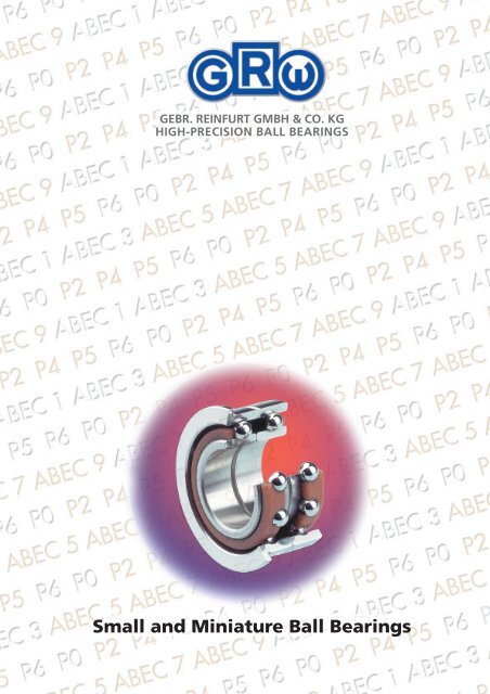
Perfection in Miniature<br />
The results of more than 50 years experience in our chosen field<br />
guarantees the precision and finish of our miniature ball bearings that can<br />
only be seen with the aid of a magnifying glass. However, these features<br />
are even more apparent when the bearings are fitted into instruments in<br />
the microelectronics, aviation and aerospace engineering, instrument, and<br />
dental fields because of their accuracy, reliability and smooth performance.<br />
If required, GRW engineers and technicians will also develop individual<br />
system solutions in addition to the standard range shown in this<br />
catalogue, for example, complete ready-to-fit units. Short development<br />
periods and short lead-times thanks to modern <strong>product</strong>ion methods mean<br />
we are able to solve a wide variety of problems, supplying units to suit<br />
every application.<br />
Contact our application engineers to discuss your technical requirements<br />
and problems. We look forward to hearing from you.<br />
Technical application support: + 49 (0)931 79 52-4 40<br />
3
Product Range<br />
Deep Groove Radial Bearings<br />
Single Row,<br />
without Filling Slot<br />
Unshielded<br />
from<br />
Bore<br />
to<br />
Outer diameter<br />
from<br />
to<br />
without flange<br />
metric<br />
Page 8 to 13<br />
1 17<br />
3 40<br />
inch<br />
Page 26 to 27<br />
.0400˝ .3750˝<br />
.1250˝ .8750˝<br />
with flange<br />
metric<br />
Page 8 to 13<br />
1,5 10<br />
4 22<br />
inch<br />
Page 26 to 27<br />
.0469˝ .3125˝<br />
.1562˝ .5000˝<br />
with extended<br />
inner ring<br />
without flange<br />
metric<br />
Page 8 to 13<br />
1,5 10<br />
4 22<br />
inch<br />
Page 26 to 27<br />
.0469˝ .3125˝<br />
.1562˝ .5000˝<br />
with extended<br />
inner ring<br />
with flange<br />
metric<br />
Page 8 to 13<br />
1,5 10<br />
4 19<br />
inch<br />
Page 26 to 27<br />
.0469˝ .3125˝<br />
.1562˝ .5000˝<br />
Special<br />
Bearings<br />
Groove<br />
in outer ring<br />
‘V’ Groove<br />
in outer ring<br />
Angular<br />
Contact<br />
4
with non-contact shield<br />
Bore<br />
Z or –2Z from<br />
to<br />
Outside Ø<br />
from<br />
to<br />
with seals<br />
TS –2TS<br />
or<br />
RS –2RS<br />
from<br />
Bore<br />
to<br />
Outside Ø<br />
from<br />
to<br />
Page 14 to 19<br />
1,5 17<br />
4 40<br />
Page 20 to 25<br />
2 17<br />
6 40<br />
Page 28 to 31<br />
.0469˝ .3750˝<br />
.1562˝ .8750˝<br />
Page 32 to 33<br />
.0781˝ .3750˝<br />
.2500˝ .8750˝<br />
Page 14 to 19<br />
1,5 10<br />
4 22<br />
Page 20 to 25<br />
2 10<br />
6 22<br />
Page 28 to 31<br />
.0469˝ .3750˝<br />
.1562˝ .8750˝<br />
Page 32 to 33<br />
.0781˝ .3750˝<br />
.2500˝ .8750˝<br />
Page 14 to 19<br />
2 10<br />
5 22<br />
Page 20 to 25<br />
2 10<br />
6 22<br />
Page 28 to 31<br />
.0469˝ .3125˝<br />
.1562˝ .5000˝<br />
Page 32 to 33<br />
.1875˝ .2500˝<br />
.3125˝ .6250˝<br />
Page 14 to 19<br />
2 10<br />
5 19<br />
Page 20 to 25<br />
2 10<br />
6 19<br />
Page 28 to 31<br />
.0469˝ .3125˝<br />
.1562˝ .5000˝<br />
Page 32 to 33<br />
.1875˝ .2500˝<br />
.3125˝ .6250˝<br />
Spherical<br />
outer ring<br />
Square groove in<br />
outer ring<br />
5
The GRW Numbering System<br />
Material Type Basic Number Closure Quality Radial Play<br />
625<br />
C2<br />
1/8 B<br />
-2Z<br />
ABEC 5<br />
K35<br />
608<br />
P4<br />
D15<br />
SS<br />
FE<br />
624<br />
-2Z<br />
P4<br />
2<br />
– SAE 52100<br />
Chrome Steel<br />
SS Stainless<br />
Steel<br />
X65Cr13<br />
HY Hybrid<br />
bearing<br />
Ceramic balls<br />
Si 3 N 4<br />
Rings made<br />
of SAE 52100<br />
Chrome Steel<br />
HYSS Hybrid<br />
bearing<br />
Ceramic balls<br />
Si 3 N 4<br />
Rings made<br />
of X65Cr13<br />
SV X30CrMoN15-1<br />
(upon request)<br />
SAE AMS 5898<br />
Page 43<br />
F Flanged<br />
outer ring<br />
E Extended<br />
inner ring<br />
Page 52<br />
Pages 8 to 33<br />
– Open bearing<br />
Z Single shield<br />
-2Z Double shield<br />
Z1 Single shield on<br />
flange side<br />
Z2 Single shield on<br />
side opposite to<br />
flange<br />
TS Single Teflon seal<br />
-2TS Double Teflon seal<br />
TS1 Single Teflon seal on<br />
flange side<br />
TS2 Single Teflon<br />
seal on opposite<br />
to flange side<br />
RS Single Perbunan<br />
rubber contact seal<br />
-2RS Double Perbunan<br />
rubber contact seal<br />
Quality grade 0<br />
is not shown<br />
See pages 34 &<br />
35 for quality<br />
information<br />
d 1 to 6 mm<br />
C2 0 to 6 µm<br />
normal 4 to 11 µm<br />
C3 10 to 20 µm<br />
C4 14 to 20 µm<br />
C5 18 to 28 µm<br />
d over 6 to 10 mm<br />
C2 0 to 6 µm<br />
normal 4 to 11 µm<br />
C3 10 to 20 µm<br />
C4 14 to 29 µm<br />
C5 20 to 37 µm<br />
d over 10 to 18 mm<br />
C2 0 to 9 µm<br />
normal 3 to 18 µm<br />
C3 11 to 25 µm<br />
C4 18 to 33 µm<br />
Normal radial play will<br />
not appear in the<br />
bearing number.<br />
RZ Single Perbunan<br />
rubber seal<br />
non-contact<br />
-2RZ Double Perbunan<br />
rubber seal<br />
non-contact<br />
VS Single Viton<br />
seal<br />
-2VS Double Viton<br />
seal<br />
Page 42<br />
C1/5 1 to 5 µm<br />
C4/8 4 to 8 µm<br />
C7/11 7 to 11 µm<br />
C10/15 10 to 15 µm<br />
C14/20 14 to 20 µm<br />
C18/28 18 to 28 µm<br />
K02 0 to .0002˝<br />
K13 .0001˝ to .0003˝<br />
K24 .0002˝ to .0004˝<br />
K35 .0003˝ to .0005˝<br />
K46 .0004˝ to .0006˝<br />
K58 .0005˝ to .0008˝<br />
D15 contact angle 15°<br />
Page 60<br />
6
Functional<br />
Tests<br />
Bore and<br />
O.D. Calibration<br />
Duplex<br />
Bearings<br />
Retainer<br />
Type<br />
Lubricant<br />
Quantity<br />
Lubricant<br />
GPR<br />
Y<br />
GPR<br />
J<br />
20%<br />
G310<br />
GPR<br />
X<br />
–1L<br />
AC1 TA<br />
L001<br />
GPR<br />
X<br />
–1<br />
J<br />
140 MG<br />
G340<br />
GPR Noise<br />
tested<br />
NG Not<br />
noise<br />
tested<br />
GPA Axial<br />
vibration<br />
tested<br />
R<br />
Followed by a<br />
figure indicates<br />
the starting<br />
torque at<br />
standard load<br />
e.g. R16 starting<br />
torque max.<br />
16 µNm<br />
Pages 46, 47<br />
X bore and O.D.<br />
in 2 Groups<br />
XB bore in 2 Groups<br />
XD O.D. in 2 Groups<br />
X4 bore and O.D.<br />
in 4 Groups<br />
X4B bore in 4 Groups<br />
X4D O.D. in 4 Groups<br />
Page 58<br />
–1 Back to back<br />
–2 Face to face<br />
–3 Tandem<br />
Pages 62, 63<br />
Preloading for<br />
spindle ball bearing<br />
L Light<br />
M Medium<br />
S Heavy<br />
Page 37<br />
Y<br />
J<br />
Brass ribbon<br />
retainer<br />
Stainless steel<br />
ribbon retainer<br />
E Steel ribbon<br />
retainer<br />
JH Stainless steel<br />
snap retainer<br />
THB Phenolic<br />
snap retainer<br />
TNH Synthetic<br />
(polyamide)<br />
snap retainer<br />
TN9H Glassfibre<br />
reinforced<br />
synthetic snap<br />
retainer<br />
AC1 One outer ring<br />
land relieved<br />
– Standard fill<br />
20% Grease<br />
volume in<br />
percent of<br />
void space<br />
140 MG Lubrication<br />
quantity in<br />
miligrams<br />
L… Oil code<br />
G… Grease code<br />
B… Special<br />
treatment<br />
Pages 44, 45<br />
AC2<br />
One inner ring<br />
land relieved<br />
AC-version only in<br />
combination with<br />
one piece solid<br />
retainer or full ball<br />
complement.<br />
Pages 37, 40, 41<br />
7
Deep Groove Ball Bearings – metric<br />
unshielded (1)<br />
Dimensions mm Types Basic Type<br />
inch<br />
according<br />
d D B B 1 rs min to DIN<br />
(2) (German<br />
Standard)<br />
1 3 1 0,05 681 618/1<br />
.0394 .1181 .0394 .002<br />
1 4 1,6 0,1 691 619/1<br />
.0394 .1575 .0630 .004<br />
1,5 4 1,2 2 0,05 68/1,5 F68/1,5 E68/1,5 FE68/1,5 618/1,5<br />
.0591 .1575 .0472 .0787 .002<br />
1,5 5 2 0,15 69/1,5 F69/1,5 619/1,5<br />
.0591 .1969 .0787 .006<br />
2 5 1,5 2,3 0,08 682 F682 E682 FE682 618/2<br />
.0787 .1969 .0591 .0906 .003<br />
2 6 2,3 3,1 0,15 692 F692 E692 FE692 619/2<br />
.0787 .2362 .0906 .1221 .006<br />
2,35(7) 5 1,5 0,08 67/2,35<br />
.0925 .1969 .0590 .003<br />
2,35(7) 5,5 2 0,08 68/2,35<br />
.0925 .2165 .0787 .003<br />
2,5 6 1,8 2,6 0,08 68/2,5 F68/2,5 E68/2,5 FE68/2,5 618/2,5<br />
.0984 .2362 .0709 .1024 .003<br />
2,5 7 2,5 3,3 0,15 69/2,5 F69/2,5 E69/2,5 FE69/2,5 619/2,5<br />
.0984 .2756 .0984 .1299 .006<br />
2,5 8 2,8 3,6 0,15 60/2,5 E60/2,5 60/2,5<br />
.0984 .3150 .1102 .1417 .006<br />
3 6 2 0,08 673 F673 617/3<br />
.1181 .2362 .0787 .003<br />
3 7 2 2,8 0,1 683 F683 E683 FE683 618/3<br />
.1181 .2756 .0787 .1102 .004<br />
3 8 2,5 0,15 693/003<br />
.1181 .3150 .0984 .006<br />
3 8 3 3,8 0,15 693 F693 E693 FE693 619/3<br />
.1181 .3150 .1181 .1496 .006<br />
3 10 4 4,8 0,15 623 F623 E623 FE623 623<br />
.1181 .3937 .1575 .1890 .006<br />
4 7 2 0,08 674 F674 617/4<br />
.1575 .2756 .0787 .003<br />
4 9 2,5 3,3 0,1 684 F684 E684 FE684 618/4<br />
.1575 .3543 .0984 .1299 .004<br />
4 11 4 4,8 0,15 694 F694 E694 FE694 619/4<br />
.1575 .4331 .1575 .1890 .006<br />
4 12 4 4,8 0,15 604 F604 E604 FE604 604<br />
.1575 .4724 .1575 .1890 .006<br />
4 13 5 5,8 0,2 624 F624 E624 FE624 624<br />
.1575 .5118 .1969 .2284 .008<br />
4 16 5 5,8 0,3 634 F634 E634 FE634 634<br />
.1575 .6299 .1969 .2284 .012<br />
4 16 5 0,3 634D 634<br />
.1575 .6299 .1969 .012<br />
8<br />
(1) Ball bearings without closure may be supplied with recesses.<br />
(2) r s min = minimum single bearing chamfer or maximum shaft or housing fillet radius.<br />
Please indicate clearly on your order if you require bearings without recesses.<br />
Types indicated in darker print are readily available. Other types can only be supplied upon special request.
r<br />
D<br />
d<br />
d a<br />
D a<br />
FD<br />
B<br />
r<br />
r<br />
FB<br />
B 1<br />
Flange Shaft & Housing Shoulders Number Ball Dia. Load Ratings Limiting<br />
Dimensions Diameters according to DIN 5418 of Balls(5) according to Speed<br />
Shaft Dia. Housing Dia. DIN ISO (6)<br />
FD FB da min da max Da max Z D w C r C or nυr<br />
(3) (4) [N] [N] [rpm]<br />
1,40 2,30 2,60 7 0,5 82 22 140.000<br />
.055 .091 .102 0.1969<br />
1,60 2,90 3,40 6 0,794 160 43 126.000<br />
.063 .141 .134 .03125<br />
5 0,4 1,90 3,10 3,60 6 0,794 163 44 113.000<br />
.197 .016 .075 .122 .142 .03125<br />
6,5 0,6 2,30 3,90 4,20 7 0,794 192 59 93.000<br />
.256 .024 .091 .154 .165 .03125<br />
6,1 0,5 2,50 3,90 4,50 7 0,794 192 59 90.000<br />
.240 .020 .098 .154 .177 .03125<br />
7,5 0,6 2,80 4,30 5,20 7 1 286 90 91.000<br />
.295 .024 .110 .169 .205 .0394<br />
2,50 3,90 4,50 7 0,794 192 59 93.000<br />
.098 .154 .177 .03125<br />
2,90 4,30 5,00 7 1 286 90 91.000<br />
.114 .169 .197 .0394<br />
7,1 0,5 3,00 4,80 5,50 7 1 289 92 81.000<br />
.280 .020 .118 .189 .217 .0394<br />
8,5 0,7 3,30 5,60 6,30 8 1,191 432 149 71.000<br />
.335 .028 .130 .220 .248 .0469<br />
3,30 5,60 7,20 8 1,191 432 149 81.000<br />
.130 .220 .283 .0469<br />
7,2 0,6 3,50 5,00 5,40 8 1 195 60 81.000<br />
.283 .024 .137 .198 .216 .0394<br />
8,1 0,5 3,60 5,70 6,40 8 1,191 432 149 71.000<br />
.319 .020 .142 .224 .252 .0469<br />
3,80 6,50 7,20 7 1,588 644 215 60.000<br />
.149 .256 .283 .0625<br />
9,5 0,7 3,80 6,50 7,20 7 1,588 644 215 67.000<br />
.375 .028 .149 .256 .283 .0625<br />
11,5 1 4,40 7,60 8,60 8 1,588 725 265 62.000<br />
.453 .039 .173 .299 .339 .0625<br />
8,2 0,6 4,50 6,00 6,50 9 1 345 130 63.000<br />
.322 .024 .177 .236 .256 .0394<br />
10,3 0,6 4,60 7,30 8,40 7 1,588 658 226 62.000<br />
.406 .024 .181 .287 .331 .0625<br />
12,5 1 4,80 7,90 10,20 8 1,588 730 271 66.000<br />
.492 .039 .183 .311 .402 .0625<br />
13,5 1 5,40 8,90 10,60 8 1,588 734 282 56.000<br />
.532 .039 .213 .350 .417 .0625<br />
15 1 5,80 10,10 11,20 7 2,381 1.339 488 52.000<br />
.591 .039 .228 .398 .441 .0938<br />
18 1 6,40 12,40 13,60 8 2,5 1.646 663 39.000<br />
.709 .039 .252 .488 .535 .0984<br />
18 1 6,40 12,40 13,60 6 3,175 1.935 677 44.000<br />
.709 .039 .252 .488 .535 .1250<br />
(3) Not applicable to bearings with extended inner ring.<br />
(4) Not applicable to flanged bearings.<br />
(5) The number of balls may vary due to different types of retainer.<br />
(6) See chapter “Limiting Speeds“, pages 48, 49.<br />
(7) Tolerance of bore +12 µm to +3 µm.<br />
Subject to change due to technical improvements.<br />
9
Deep Groove Ball Bearings – metric<br />
unshielded (1)<br />
Dimensions mm Types Basic Type<br />
inch<br />
according<br />
d D B B 1 rs min to DIN<br />
(2) (German<br />
Standard)<br />
5 8 2 0,08 675 F675 617/5<br />
.1969 .3150 .0787 .003<br />
5 11 3 3,8 0,15 685 F685 E685 FE685 618/5<br />
.1969 .4331 .1181 .1496 .006<br />
5 13 4 4,8 0,2 695 F695 E695 FE695 619/5<br />
.1969 .5118 .1575 .1890 .008<br />
5 14 5 5,8 0,2 605 F605 E605 FE605 605<br />
.1969 .5512 .1969 .2284 .008<br />
5 16 5 5,8 0,3 625 F625 E625 FE625 625<br />
.1969 .6299 .1969 .2284 .012<br />
5 16 5 0,3 625D 625<br />
.1969 .6299 .1969 .012<br />
5 19 6 6,8 0,3 635 F635 E635 FE635 635<br />
.1969 .7480 .2362 .2677 .012<br />
6 10 2,5 0,15 676(8) 617/6<br />
.2362 .3937 .0984 .006<br />
6 13 3,5 4,3 0,15 686 F686 E686 FE686 618/6<br />
.2362 .5118 .1378 .1693 .006<br />
6 15 5 5,8 0,2 696 F696 E696 FE696 619/6<br />
.2362 .5906 .1969 .2284 .008<br />
6 16 5 0,3 625/0002<br />
.2362 .6299 .1969 .012<br />
6 19 6 6,8 0,3 626 F626 E626 FE626 626<br />
.2362 .7480 .2362 .2677 .012<br />
7 11 2,5 0,15 677(8) 617/7<br />
.2756 .4331 .0984 .006<br />
7 14 3,5 4,3 0,15 687 F687 E687 FE687 618/7<br />
.2756 .5512 .1378 .1693 .006<br />
7 17 5 5,8 0,3 697 F697 E697 FE697 619/7<br />
.2756 .6693 .1969 .2284 .012<br />
7 19 6 6,8 0,3 607 F607 E607 FE607 607<br />
.2756 .7480 .2362 .2677 .012<br />
7 22 7 0,3 627 F627 627<br />
.2756 .8661 .2756 .012<br />
8 12 2,5 0,15 678(8) 617/8<br />
.3150 .4724 .0984 .006<br />
8 16 4 4,8 0,2 688 F688 E688 FE688 618/8<br />
.3150 .6299 .1575 .1890 .008<br />
8 19 6 6,8 0,3 698 F698 E698 FE698 619/8<br />
.3150 .7480 .2362 .2677 .012<br />
8 22 6 0,3 608/003<br />
.3150 .8661 .2362 .012<br />
8 22 7 0,3 608 F608 E608 FE608 608<br />
.3150 .8661 .2756 .012<br />
9 14 3 0,15 679 617/9<br />
.3543 .5512 .1181 .006<br />
9 17 4 4,8 0,2 689 F689 E689 FE689 618/9<br />
.3543 .6693 .1575 .1890 .008<br />
10<br />
(1) Ball bearings without closure may be supplied with recesses.<br />
(2) r s min = minimum single bearing chamfer or maximum shaft or housing fillet radius.<br />
Please indicate clearly on your order if you require bearings without recesses.<br />
Types indicated in darker print are readily available. Other types can only be supplied upon special request.
D<br />
d<br />
r<br />
d a<br />
D a<br />
FD<br />
B<br />
r<br />
r<br />
FB B 1<br />
Flange Shaft & Housing Shoulders Number Ball Dia. Load Ratings Limiting<br />
Dimensions Diameters according to DIN 5418 of Balls(5) according to Speed<br />
Shaft Dia. Housing Dia. DIN ISO (6)<br />
FD FB da min da max Da max Z D w C r C or nυr<br />
(3) (4) [N] [N] [rpm]<br />
9,2 0,6 5,50 7,00 7,50 11 1 390 160 52.000<br />
.362 .024 .217 .276 .295 .0394<br />
12,5 0,8 5,80 6,70 10,70 8 1,588 734 282 52.000<br />
.492 .032 .228 .264 .421 .0625<br />
15 1 6,40 9,70 11,60 10 1,588 851 366 49.000<br />
.591 .039 .252 .382 .457 .0625<br />
16 1 6,40 10,80 12,60 8 1,984 1.096 437 50.000<br />
.630 .039 .252 .425 .496 .0781<br />
18 1 7,40 12,40 13,60 8 2,5 1.646 663 40.000<br />
.709 .039 .291 .488 .357 .0984<br />
18 1 7,40 12,40 13,60 6 3,175 1.935 677 45.000<br />
.709 .039 .291 .488 .357 .1250<br />
22 1,5 7,40 15,10 16,60 8 3,175 2.522 1.057 33.000<br />
.868 .059 .291 .594 .654 .1250<br />
6,50 8,00 8,50 10 1,191 503 215 46.000<br />
.256 .315 .335 .0469<br />
15 1 6,80 10,80 12,20 8 1,984 1.096 437 44.000<br />
.591 .039 .268 .425 .480 .0781<br />
17 1,2 7,40 11,50 13,60 9 1,984 1.186 505 46.000<br />
.669 .047 .291 .453 .535 .0781<br />
8,40 12,40 13,60 8 2,5 1.646 663 41.000<br />
.331 .488 .535 .0984<br />
22 1,5 8,40 15,10 16,60 8 3,175 2.522 1.057 34.000<br />
.866 .059 .331 .594 .654 .1250<br />
7,50 9,00 9,50 9 1,191 462 199 40.000<br />
.295 .354 .374 .0469<br />
16 1 7,80 11,60 13,20 9 1,984 1.186 505 41.000<br />
.630 .039 .307 .457 .520 .0781<br />
19 1,2 9,00 13,60 15,00 9 2,5 1.795 776 39.000<br />
.748 .047 .354 .535 .591 .0984<br />
22 1,5 9,00 15,10 17,00 8 3,175 2.522 1.057 38.000<br />
.866 .059 .354 .594 .669 .1250<br />
25 1,5 9,40 17,30 19,60 7 3,969 3.369 1.363 35.000<br />
.984 .059 .370 .681 .772 .15625<br />
8,50 10,00 10,50 12 1,191 551 270 35.000<br />
.335 .394 .413 .0469<br />
18 1 9,40 13,50 14,60 9 2,5 1.795 776 38.000<br />
.709 .039 .370 .531 .575 .0984<br />
22 1,5 10,00 14,60 17,00 9 2,5 1.798 797 40.000<br />
.866 .059 .394 .574 .669 .0984<br />
10,00 17,30 20,00 7 3,969 3.369 1.363 34.000<br />
.394 .681 .787 .15625<br />
25 1,5 10,00 17,30 20,00 7 3,969 3.369 1.363 38.000<br />
.984 .059 .394 .681 .787 .15625<br />
9,50 11,00 12,50 12 1,191 536 276 33.000<br />
.374 .433 .492 .0469<br />
19 1 10,40 14,50 15,60 9 2,5 1.798 797 34.000<br />
.748 .039 .409 .571 .614 .0984<br />
(3) Not applicable to bearings with extended inner ring.<br />
(4) Not applicable to flanged bearings.<br />
(5) The number of balls may vary due to different types of retainer.<br />
(6) See chapter “Limiting Speeds“, pages 48, 49.<br />
(8) Available in different width with closure.<br />
Subject to change due to technical improvements.<br />
11
Deep Groove Ball Bearings – metric<br />
unshielded (1)<br />
Dimensions mm Types Basic Type<br />
inch<br />
according<br />
d D B B 1 rs min to DIN<br />
(2) (German<br />
Standard)<br />
9 20 6 0,3 699 619/9<br />
.3543 .7874 .2362 .012<br />
9 24 7 0,3 609 609<br />
.3543 .9449 .2756 .012<br />
9 24 7 0,3 609D 609<br />
.3543 .9449 .2756 .012<br />
9 26 8 0,3 629 629<br />
.3543 1.0236 .3150 .012<br />
10 15 3 0,15 6700(8) 61700<br />
.3937 .5906 .1181 .006<br />
10 19 5 5,8 0,3 6800 F6800 E6800 FE6800 61800<br />
.3937 .7488 .1969 .2284 .012<br />
10 22 6 0,3 6900 61900<br />
.3937 .8661 .2362 .012<br />
10 26 8 0,3 6000 6000<br />
.3937 1.0236 .3150 .012<br />
10 30 9 0,6 6200 6200<br />
.3937 1.181 .3543 .024<br />
10 30 9 0,6 6200D 6200<br />
.3937 1.0236 .3543 .024<br />
12 21 5 0,3 6801 61801<br />
.4724 .8267 .1969 .012<br />
12 24 6 0,3 6901 61901<br />
.4724 .9449 .2362 .012<br />
12 28 8 0,3 6001 6001<br />
.4724 1.1024 .3150 .012<br />
12 32 10 0,6 6201 6201<br />
.4724 1.2598 .3937 .024<br />
15 24 5 0,3 6802 61802<br />
.5906 .9449 .1969 .012<br />
15 28 7 0,3 6902 61902<br />
.5906 1.1024 .2756 .012<br />
15 32 9 0,3 6002 6002<br />
.5906 1.2598 .3543 .012<br />
15 35 11 0,6 6202 6202<br />
.5906 1.3780 .4331 .024<br />
17 26 5 0,3 6803 61803<br />
.6693 1.0236 .1969 .012<br />
17 30 7 0,3 6903 61903<br />
.6693 1.1811 .2756 .012<br />
17 35 10 0,3 6003 6003<br />
.6693 1.3780 .3937 .012<br />
17 40 12 0,6 6203 6203<br />
.6693 1.5748 .4724 .024<br />
12<br />
(1) Ball bearings without closure may be supplied with recesses.<br />
(2) r s min = minimum single bearing chamfer or maximum shaft or housing fillet radius.<br />
Please indicate clearly on your order if you require bearings without recesses.<br />
Types indicated in darker print are readily available. Other types can only be supplied upon special request.
D<br />
d<br />
r<br />
d a<br />
D a<br />
FD<br />
B<br />
r<br />
r<br />
FB B 1<br />
Flange Shaft & Housing Shoulders Number Ball Dia. Load Ratings Limiting<br />
Dimensions Diameters according to DIN 5418 of Balls(5) according to Speed<br />
Shaft Dia. Housing Dia. DIN ISO (6)<br />
FD FB da min da max Da max Z D w C r C or nυr<br />
(3) (4) [N] [N] [rpm]<br />
11,00 15,80 18,00 10 2,5 1.922 915 35.000<br />
.433 .622 .709 .0984<br />
11,00 18,90 22,00 7 3,969 3.435 1.430 33.000<br />
.433 .744 .866 .15625<br />
11,00 18,90 22,00 8 3,969 3.758 1.632 32.000<br />
.433 .744 .866 .15625<br />
11,40 20,70 23,60 7 4,763 4.698 1.982 29.000<br />
.499 .815 .929 .1875<br />
10,50 12,00 13,50 11 1,588 881 435 30.000<br />
.413 .472 .532 .0625<br />
21 1 12,00 15,80 17,00 10 2,5 1.922 915 34.000<br />
.827 .039 .472 .622 .669 .0984<br />
12,00 17,80 20,00 8 3,175 2.555 1.129 31.000<br />
.472 .701 .787 .1250<br />
12,40 20,70 23,60 7 4,763 4.698 1.982 32.000<br />
.488 .815 .929 .1875<br />
14,20 23,20 25,80 7 5,556 6.100 2.600 29.000<br />
.559 .913 1.016 .2188<br />
14,20 23,20 25,80 8 4,763 5.236 2.374 27.000<br />
.559 .913 1.016 .1875<br />
14,00 17,90 19,00 12 2,381 1.930 900 30.000<br />
.551 .705 .748 .09375<br />
14,00 16,30 22,00 10 3,175 2.971 1.452 34.000<br />
.551 .641 .866 .1250<br />
14,00 24,10 26,00 9 3,969 5.237 2.359 31.000<br />
.559 .945 1.024 .15625<br />
16,22 27,00 27,80 7 6 7.073 3.100 26.000<br />
.639 1.063 1.095 .2363<br />
17,00 20,90 22,00 14 2,381 2.080 1.100 24.000<br />
.669 .823 .866 .09375<br />
17,00 19,00 26,00 11 3,175 4.445 2.268 32.000<br />
.669 .748 1.024 .1250<br />
17,00 27,90 30,00 9 4,763 5.676 2.819 26.000<br />
.669 1.098 1.181 .1875<br />
19,20 30,20 30,90 8 6 7.939 3.744 23.000<br />
.756 1.189 .819 .2362<br />
19,00 22,90 24,00 16 2,381 2.240 1.270 22.000<br />
.748 .902 .945 .09375<br />
19,00 20,90 28,00 11 3,969 4.723 2.547 30.000<br />
.748 .823 1.102 .15625<br />
19,00 30,40 33,00 10 4,763 6.172 3.267 23.000<br />
.748 1.197 1.299 .1875<br />
21,20 34,00 35,80 8 6,747 9.811 4.734 20.000<br />
.835 1.339 1.409 .2656<br />
(3) Not applicable to bearings with extended inner ring.<br />
(4) Not applicable to flanged bearings.<br />
(5) The number of balls may vary due to different types of retainer.<br />
(6) See chapter “Limiting Speeds“, pages 48, 49.<br />
(8) Available in different width with closure.<br />
Subject to change due to technical improvements.<br />
13
Deep Groove Ball Bearings – metric<br />
with non-contact shield<br />
Dimensions mm Types Basic Type<br />
inch<br />
according<br />
d D B B 1 rs min to DIN<br />
(2) (German<br />
Standard)<br />
1,5 4 2 0,05 68/1,5-2Z F68/1,5-2Z 638/1,5<br />
.0591 .1575 .0787 .002<br />
1,5 5 2 0,15 69/1,5/002-2Z 619/1,5<br />
.0591 .1969 .0787 .006<br />
1,5 5 2,6 0,15 69/1,5-2Z F69/1,5-2Z 639/1,5<br />
.0591 .1969 .1924 .006<br />
2 5 2,3 3,1 0,08 682-2Z F682-2Z E682-2Z FE682-2Z 638/2<br />
.0787 .1969 .0906 .1221 .003<br />
2 6 2,3 3,1 0,15 692-2Z F692-2Z E692-2Z FE692-2Z 619/2<br />
.0787 .2362 .0906 .1221 .006<br />
2,35(7) 5 2,3 0,08 67/2,35-2Z<br />
.0925 .1969 .0906 .003<br />
2,5 6 2,6 3,4 0,08 68/2,5-2Z F68/2,5-2Z E68/2,5-2Z FE68/2,5-2Z 638/2,5<br />
.0984 .2362 .1024 .1339 .003<br />
2,5 7 3 0,1 683/0001-2Z F683/0001-2Z<br />
.0984 .2756 .1181 .004<br />
2,5 7 3,5 4,3 0,15 69/2,5-2Z F69/2,5-2Z E69/2,5-2Z FE69/2,5-2Z 639/2,5<br />
.0984 .2756 .1378 .1693 .006<br />
2,5 8 2,8 3,6 0,15 60/2,5-2Z E60/2,5-2Z 60/2,5<br />
.0984 .3150 .1102 .1417 .006<br />
3 6 2 0,08 673-2Z 617/3<br />
.1181 .2362 .0787 .003<br />
3 7 3 3,8 0,1 683-2Z F683-2Z E683-2Z FE683-2Z 638/3<br />
.1181 .2756 .1181 .1496 .004<br />
3 8 3 3,8 0,15 693/002-2Z F693/002-2Z E693/002-2Z FE693/002-2Z 619/3<br />
.1181 .3150 .1181 .1496 .006<br />
3 8 4 4,8 0,15 693-2Z F693-2Z E693-2Z FE693-2Z 639/3<br />
.1181 .3150 .1575 .1890 .006<br />
3 10 4 4,8 0,15 623-2Z F623-2Z E623-2Z FE623-2Z 623<br />
.1181 .3997 .1575 .1890 .006<br />
4 7 2 0,08 674-2Z 617/4<br />
.1575 .2756 .0787 .003<br />
4 9 4 4,8 0,1 684-2Z F684-2Z E684-2Z FE684-2Z 638/4<br />
.1575 .3543 .1575 .1890 .004<br />
4 10 4 4,8 0,1 684/10-2Z F684/10-2Z E684/10-2Z FE684/10-2Z<br />
.1575 .3997 .1575 .1890 .004<br />
4 11 4 4,8 0,15 694-2Z F694-2Z E694-2Z FE694-2Z 619/4<br />
.1575 .4331 .1575 .1890 .006<br />
4 12 4 4,8 0,15 604-2Z F604-2Z E604-2Z FE604-2Z 604<br />
.1575 .4724 .1575 .1890 .006<br />
4 13 5 5,8 0,2 624-2Z F624-2Z E624-2Z FE624-2Z 624<br />
.1575 .5118 .1969 .2284 .008<br />
4 16 5 5,8 0,3 634-2Z F634-2Z E634-2Z FE634-2Z 634<br />
.1575 .6299 .1969 .2284 .012<br />
4 16 5 0,3 634D-2Z 634<br />
.1575 .6299 .1969 .012<br />
14<br />
(2) r s min = minimum single bearing chamfer or maximum shaft or housing fillet radius.<br />
Types indicated in darker print are readily available. Other types can only be supplied upon special request.
D<br />
d<br />
r<br />
d a<br />
D a<br />
FD<br />
B<br />
r<br />
r<br />
FB B 1<br />
Flange Shaft & Housing Shoulders Number Ball Dia. Load Ratings Limiting<br />
Dimensions Diameters according to DIN 5418 of Balls(5) according to Speed<br />
Shaft Dia. Housing Dia. DIN ISO (6)<br />
FD FB da min da max Da max Z D w C r C or nυr<br />
(3) (4) [N] [N] [rpm]<br />
5 0,6 1,90 2,35 3,60 6 0,794 163 44 153.000<br />
.197 .024 .075 .093 .142 .03125<br />
2,30 2,95 4,20 7 0,794 192 59 93.000<br />
.091 .116 .165 .03125<br />
6,5 0,8 2,30 2,95 4,20 7 0,794 192 59 109.000<br />
.256 .032 .091 .116 .165 .03125<br />
6,1 0,6 2,50 2,95 4,50 7 0,794 192 59 116.000<br />
.240 .024 .098 .116 .177 .03125<br />
7,5 0,6 2,80 3,25 5,20 7 1 286 90 91.000<br />
.295 .024 .110 .128 .205 .0394<br />
2,50 3,90 4,50 7 0,794 192 59 120.000<br />
.098 .154 .177 .03125<br />
7,1 0,8 3,00 3,50 5,50 7 1 289 92 101.000<br />
.280 .032 .118 .138 .217 .0394<br />
8,1 0,8 3,10 4,10 6,40 8 1,191 432 149 88.000<br />
.319 .032 .142 .161 .252 .0469<br />
8,5 0,9 3,30 4,10 6,30 8 1,191 432 149 87.000<br />
.335 .035 .130 .161 .248 .0469<br />
3,30 4,10 7,20 8 1,191 432 149 81.000<br />
.130 .161 .283 .0469<br />
3,50 5,00 5,40 8 1 195 60 81.000<br />
.137 .198 .216 .0394<br />
8,1 0,8 3,60 4,10 6,40 8 1,191 432 149 90.000<br />
.319 .032 .142 .161 .252 .0469<br />
9,5 0,7 3,80 4,55 7,20 7 1,588 644 215 67.000<br />
.375 .028 .149 .179 .283 .0625<br />
9,5 0,9 3,80 4,55 7,20 7 1,588 644 215 80.000<br />
.375 .035 .149 .179 .283 .0625<br />
11,5 1 4,40 5,50 8,60 8 1,588 725 265 65.000<br />
.453 .039 .173 .217 .339 .0625<br />
4,50 4,75 6,50 9 1 345 130 63.000<br />
.177 .187 .256 .0394<br />
10,3 1 4,60 5,15 8,40 7 1,588 658 226 82.000<br />
.406 .039 .181 .203 .331 .0625<br />
11,5 1 4,60 5,15 9,40 7 1,588 658 226 86.000<br />
.453 .039 .181 .203 .370 .0625<br />
12,5 1 4,80 5,95 10,20 8 1,588 730 271 66.000<br />
.492 .039 .189 .234 .402 .0625<br />
13,5 1 5,40 6,70 10,60 8 1,588 734 282 56.000<br />
.532 .039 .213 .264 .417 .0625<br />
15 1 5,80 6,90 11,20 7 2,381 1.339 488 52.000<br />
.591 .039 .228 .272 .441 .0938<br />
18 1 6,40 9,00 13,60 8 2,5 1.646 663 44.000<br />
.709 .039 .252 .354 .535 .0984<br />
18 1 6,40 9,00 13,60 6 3,175 1.935 677 45.000<br />
.709 .039 .252 .354 .535 .1250<br />
(3) Not applicable to bearings with extended inner ring.<br />
(4) Not applicable to flanged bearings.<br />
(5) The number of balls may vary due to different types of retainer.<br />
(6) See chapter “Limiting Speeds“, pages 48, 49.<br />
(7) Tolerance of bore +12 µm to +3 µm.<br />
Subject to change due to technical improvements.<br />
15
Deep Groove Ball Bearings – metric<br />
with non-contact shield<br />
Dimensions mm Types Basic Type<br />
inch<br />
according<br />
d D B B 1 rs min to DIN<br />
(2) (German<br />
Standard)<br />
5 8 2 0,08 675-2Z 617/5<br />
.1969 .3150 .0787 .003<br />
5 10 4 0,08 694/1002-2Z<br />
.1969 .3997 .1575 .003<br />
5 11 4 0,15 685/003-2Z F685/003-2Z 628/5<br />
.1969 .4331 .1575 .006<br />
5 11 5 5,8 0,15 685-2Z F685-2Z E685-2Z FE685-2Z 638/5<br />
.1969 .4331 .1969 .2284 .006<br />
5 13 4 4,8 0,2 695-2Z F695-2Z E695-2Z FE695-2Z 619/5<br />
.1969 .5118 .1575 .1890 .008<br />
5 13 5 0,2 624/0003-2Z<br />
.1969 .5118 .1969 .008<br />
5 14 5 5,8 0,2 605-2Z F605-2Z E605-2Z FE605-2Z 605<br />
.1969 .5512 .1969 .2284 .008<br />
5 16 5 5,8 0,3 625-2Z F625-2Z E625-2Z FE625-2Z 625<br />
.1969 .6299 .1969 .2284 .012<br />
5 16 5 0,3 625D-2Z 625<br />
.1969 .6299 .1969 .012<br />
5 19 6 6,8 0,3 635-2Z F635-2Z E635-2Z FE635-2Z 635<br />
.1969 .7480 .2362 .2677 .012<br />
6 12 4 0,15 695/1202-2Z<br />
.2362 .4724 .1575 .006<br />
6 13 5 5,8 0,15 686-2Z F686-2Z E686-2Z FE686-2Z 628/6<br />
.2362 .5118 .1969 .2284 .006<br />
6 15 5 5,8 0,2 696-2Z F696-2Z E696-2Z FE696-2Z 619/6<br />
.2362 .5906 .1969 .2284 .008<br />
6 16 5 0,3 625/0002-2Z<br />
.2362 .6299 .1969 .012<br />
6 19 6 6,8 0,3 626-2Z F626-2Z E626-2Z FE626-2Z 626<br />
.2362 .7480 .2362 .2677 .012<br />
7 14 5 5,8 0,15 687-2Z F687-2Z E687-2Z FE687-2Z 628/7<br />
.2756 .5512 .1969 .2284 .006<br />
7 17 5 5,8 0,3 697-2Z F697-2Z E697-2Z FE697-2Z 619/7<br />
.2756 .6693 .1969 .2284 .012<br />
7 19 6 6,8 0,3 607-2Z F607-2Z E607-2Z FE607-2Z 607<br />
.2756 .7480 .2362 .2677 .012<br />
7 22 7 0,3 627-2Z F627-2Z 627<br />
.2756 .8661 .2756 .012<br />
8 14 4 0,2 688A/142-2Z<br />
.3150 .5512 .1575 .008<br />
8 16 5 0,2 688/003-2Z F688/003-2Z 628/8<br />
.3150 .6299 .1969 .012<br />
8 16 6 6,8 0,2 688-2Z F688-2Z E688-2Z FE688-2Z 638/8<br />
.3150 .6299 .2362 .2677 .008<br />
8 19 6 6,8 0,3 698-2Z F698-2Z E698-2Z FE698-2Z 619/8<br />
.3150 .7480 .2362 .2677 .012<br />
8 22 7 0,3 608-2Z F608-2Z 608<br />
.3150 .8661 .2756 .012<br />
16<br />
(2) r s min = minimum single bearing chamfer or maximum shaft or housing fillet radius.<br />
Types indicated in darker print are readily available. Other types can only be supplied upon special request.
D<br />
d<br />
r<br />
d a<br />
D a<br />
FD<br />
B<br />
r<br />
r<br />
FB B 1<br />
Flange Shaft & Housing Shoulders Number Ball Dia. Load Ratings Limiting<br />
Dimensions Diameters according to DIN 5418 of Balls(5) according to Speed<br />
Shaft Dia. Housing Dia. DIN ISO (6)<br />
FD FB da min da max Da max Z D w C r C or nυr<br />
(3) (4) [N] [N] [rpm]<br />
5,50 5,75 7,50 11 1 390 160 52.000<br />
.217 .226 .295 .0394<br />
5,50 8,10 8,80 8 1,588 730 271 66.000<br />
.216 .319 .347 .0625<br />
12,5 1 5,80 6,70 10,70 8 1,588 734 282 62.000<br />
.492 .039 .228 .264 .421 .0625<br />
12,5 1 5,80 6,70 10,70 8 1,588 734 282 71.000<br />
.492 .039 .228 .264 .421 .0625<br />
15 1 6,40 7,75 11,60 10 1,588 851 366 49.000<br />
.591 .039 .252 .305 .457 .0625<br />
5,80 6,90 11,20 7 2,381 1.339 488 53.000<br />
.228 .272 .441 .0938<br />
16 1 6,40 8,20 12,60 8 1,984 1.096 437 50.000<br />
.630 .039 .252 .323 .496 .0781<br />
18 1 7,40 9,00 13,60 8 2,5 1.646 663 50.000<br />
.709 .039 .291 .354 .535 .0984<br />
18 1 7,40 9,00 13,60 6 3,175 1.935 677 42.000<br />
.709 .039 .291 .354 .535 .1250<br />
22 1,5 7,40 10,80 16,60 8 3,175 2.522 1.057 35.000<br />
.866 .059 .291 .425 .654 .1250<br />
6,80 7,75 11,20 10 1,588 851 366 49.000<br />
.268 .305 .441 .0625<br />
15 1,1 6,80 8,20 12,20 8 1,984 1.096 437 55.000<br />
.591 .043 .268 .323 .480 .0781<br />
17 1,2 7,40 9,00 13,60 9 1,984 1.186 505 46.000<br />
.669 .047 .291 .354 .535 .0781<br />
8,40 9,00 13,60 8 2,5 1.646 663 41.000<br />
.331 .354 .535 .0984<br />
22 1,5 8,40 10,80 16,60 8 3,175 2.522 1.057 34.000<br />
.866 .059 .331 .425 .654 .1250<br />
16 1,1 7,80 9,00 13,20 9 1,984 1.186 505 50.000<br />
.630 .043 .307 .354 .520 .0781<br />
19 1,2 9,00 10,10 15,00 9 2,5 1.795 776 39.000<br />
.748 .047 .354 .398 .591 .0984<br />
22 1,5 9,00 10,80 17,00 8 3,175 2.522 1.057 38.000<br />
.866 .059 .354 .425 .669 .1250<br />
25 1,5 9,40 11,60 19,60 7 3,969 3.369 1.363 35.000<br />
.984 .059 .370 .457 .772 .15625<br />
9,40 9,40 12,60 12 1,191 335 152 47.000<br />
.370 .370 .496 .0469<br />
18 1,1 9,40 10,10 14,60 9 2,5 1.795 776 43.000<br />
.709 .043 .370 .398 .575 .0984<br />
18 1,3 9,40 10,10 14,60 9 2,5 1.795 776 48.000<br />
.709 .051 .370 .398 .575 .0984<br />
22 1,5 10,00 11,10 17,00 9 2,5 1.798 797 40.000<br />
.866 .059 .394 .437 .669 .0984<br />
25 1,5 10,00 11,60 20,00 7 3,969 3.369 1.363 38.000<br />
.984 .059 .394 .457 .787 .15625<br />
(3) Not applicable to bearings with extended inner ring.<br />
(4) Not applicable to flanged bearings.<br />
(5) The number of balls may vary due to different types of retainer.<br />
(6) See chapter “Limiting Speeds“, pages 48, 49.<br />
Subject to change due to technical improvements.<br />
17
Deep Groove Ball Bearings – metric<br />
with non-contact shield<br />
Dimensions mm Types Basic Type<br />
inch<br />
according<br />
d D B B 1 rs min to DIN<br />
(2) (German<br />
Standard)<br />
9 17 6 6,8 0,2 689-2Z F689-2Z E689-2Z FE689-2Z 638/9<br />
.3543 .6693 .2362 .2677 .008<br />
9 20 6 0,3 699-2Z 619/9<br />
.3543 .7874 .2362 .012<br />
9 24 7 0,3 609-2Z 609<br />
.3543 .9449 .2756 .012<br />
9 24 7 0,3 609D-2Z 609<br />
.3543 .9449 .2756 .012<br />
9 26 8 0,3 629-2Z 629<br />
.3543 1.0236 .3150 .012<br />
10 19 5 0,3 6800/002-2Z F6800/002-2Z 61800<br />
.3937 .7480 .1969 .012<br />
10 19 7 7,8 0,3 6800-2Z F6800-2Z E6800-2Z FE6800-2Z 63800<br />
.3937 .7480 .2756 .3071 .012<br />
10 22 6 0,3 6900-2Z 61900<br />
.3937 .8661 .2362 .012<br />
10 26 8 0,3 6000-2Z 6000<br />
.3937 1.0236 .3150 .012<br />
10 30 9 0,6 6200-2Z 6200<br />
.3937 1.181 .3543 .024<br />
10 30 9 0,6 6200D-2Z 6200<br />
.3937 1.181 .3543 .024<br />
12 21 5 0,3 6801-2Z 61801<br />
.4724 .8267 .1969 .012 6801-2RZ<br />
12 24 6 0,3 6901-2Z 61901<br />
.4724 .9449 .2362 .012 6901-2RZ<br />
12 28 8 0,3 6001-2Z 6001<br />
.4724 1.1024 .3150 .012<br />
12 32 10 0,6 6201-2Z 6201<br />
.4724 1.2598 .3937 .024<br />
15 24 5 0,3 6802-2Z 61802<br />
.5906 .9449 .1969 .012 6802-2RZ<br />
15 28 7 0,3 6902-2Z 61902<br />
.5906 1.1024 .2756 .012 6902-2RZ<br />
15 32 9 0,3 6002-2Z 6002<br />
.5906 1.2598 .3543 .012<br />
15 35 11 0,6 6202-2Z 6202<br />
.5906 1.3780 .4331 .024<br />
17 26 5 0,3 6803-2Z 61803<br />
.6693 1.0236 .1969 .012 6803-2RZ<br />
17 30 7 0,3 6903-2Z 61903<br />
.6693 1.1811 .2756 .012 6903-2RZ<br />
17 35 10 0,3 6003-2Z 6003<br />
.6693 1.3780 .3937 .012<br />
17 40 12 0,6 6203-2Z 6203<br />
.6693 1.5748 .4724 .024<br />
18<br />
(2) r s min = minimum single bearing chamfer or maximum shaft or housing fillet radius.<br />
Types indicated in darker print are readily available. Other types can only be supplied upon special request.
D<br />
d<br />
r<br />
d a<br />
D a<br />
FD<br />
B<br />
r<br />
r<br />
FB B 1<br />
Flange Shaft & Housing Shoulders Number Ball Dia. Load Ratings Limiting<br />
Dimensions Diameters according to DIN 5418 of Balls(5) according to Speed<br />
Shaft Dia. Housing Dia. DIN ISO (6)<br />
FD FB da min da max Da max Z D w C r C or nυr<br />
(3) (4) [N] [N] [rpm]<br />
19 1,3 10,40 11,10 15,60 9 2,5 1.798 797 44.000<br />
.748 .051 .409 .437 .614 .0984<br />
11,00 12,60 18,00 10 2,5 1.922 915 35.000<br />
.433 .496 .709 .0984<br />
11,00 13,45 22,00 7 3,969 3.435 1.430 33.000<br />
.433 .530 .866 .15625<br />
11,90 18,90 22,00 8 3,969 3.758 1.632 32.000<br />
.433 .744 .866 .15625<br />
11,40 14,60 23,60 7 4,763 4.698 1.982 34.000<br />
.449 .575 .929 .1875<br />
21 1 12,00 12,60 17,00 10 2,5 1.922 915 34.000<br />
.827 .039 .472 .496 .669 .0984<br />
21 1,5 12,00 12,60 17,00 10 2,5 1.922 915 42.000<br />
.827 .059 .472 .496 .669 .0984<br />
12,00 13,45 20,00 8 3,175 2.555 1.129 31.000<br />
.472 .530 .787 .1250<br />
12,40 14,60 23,60 7 4,763 4.698 1.982 35.000<br />
.488 .575 .929 .1875<br />
14,20 16,00 25,80 7 5,556 6.100 2.600 27.000<br />
.559 .623 1.016 .2188<br />
14,20 16,00 25,80 8 4,763 5.236 2.374 27.000<br />
.559 .623 1.016 .1875<br />
14,00 14,50 19,00 12 2,381 1.930 900 30.000<br />
.551 .571 .748 .09375<br />
14,00 15,60 22,00 10 3,175 2.971 1.452 27.000<br />
.559 .614 .866 .1250<br />
14,00 16,10 26,00 9 3,969 5.237 2.359 28.000<br />
.559 .634 1.024 .15625<br />
16,22 17,70 27,80 7 6 7.073 3.100 26.000<br />
.639 .697 1.095 .2362<br />
17,00 17,50 22,00 14 2,381 2.080 1.100 25.000<br />
.669 .689 .866 .09375<br />
17,00 18,25 26,00 11 3,969 4.445 2.268 24.000<br />
.669 .719 1.024 .15625<br />
17,00 19,60 30,00 9 4,763 5.676 2.819 25.000<br />
.669 .772 1.181 .1865<br />
19,20 20,50 30,80 8 6 7.939 3.744 24.000<br />
.726 .807 .819 .2362<br />
19,00 19,50 24,00 16 2,381 2.240 1.270 22.000<br />
.748 .768 .945 .09375<br />
19,00 20,15 28,00 11 3,969 4.723 2.547 21.000<br />
.748 .793 1.102 .15625<br />
19,00 22,10 33,00 10 4,763 6.172 3.267 23.000<br />
.748 .870 1.299 .1875<br />
21,20 23,50 35,80 8 6,747 9.811 4.734 20.000<br />
.835 .925 1.409 .2656<br />
(3) Not applicable to bearings with extended inner ring.<br />
(4) Not applicable to flanged bearings.<br />
(5) The number of balls may vary due to different types of retainer.<br />
(6) See chapter “Limiting Speeds“, pages 48, 49.<br />
Subject to change due to technical improvements.<br />
19
Deep Groove Ball Bearings – metric<br />
with seal<br />
Dimensions mm Types Basic Type<br />
inch<br />
according<br />
d D B B 1 rs min to DIN<br />
(2) (German<br />
Standard)<br />
1,5 5 2,6 0,15 69/1,5-2TS F69/1,5-2TS 639/1,5<br />
.0591 .1969 .1024 .006<br />
2 5 2,3 3,1 0,08 682-2TS F682-2TS E682-2TS FE682-2TS 638/2<br />
.0787 .1969 .0906 .1221 .003<br />
2 6 2,3 3,1 0,15 692-2TS F692-2TS E692-2TS FE692-2TS 619/2<br />
.0787 .2362 .0906 .1221 .006<br />
2,5 6 2,6 3,4 0,08 68/2,5-2TS F68/2,5-2TS E68/2,5-2TS FE68/2,5-2TS 638/2,5<br />
.0984 .2362 .1024 .1339 .003<br />
2,5 7 3,5 4,3 0,15 69/2,5-2TS F69/2,5-2TS E69/2,5-2TS FE69/2,5-2TS 639/2,5<br />
.0984 .2756 .1378 .1693 .006<br />
2,5 8 2,8 3,6 0,15 60/2,5-2TS E60/2,5-2TS 60/2,5<br />
.0984 .3150 .1102 .1417 .006<br />
3 7 3 3,8 0,1 683-2TS F683-2TS E683-2TS FE683-2TS 638/3<br />
.1181 .2756 .1181 .1496 .004<br />
3 8 4 4,8 0,15 693-2TS F693-2TS E693-2TS FE693-2TS 639/3<br />
.1181 .3150 .1575 .1890 .006<br />
3 10 4 4,8 0,15 623-2TS F623-2TS E623-2TS FE623-2TS 623<br />
.1181 .3937 .1575 .1890 .006<br />
4 9 4 4,8 0,1 684-2TS F684-2TS E684-2TS FE684-2TS 638/4<br />
.1575 .3543 .1575 .1890 .004<br />
4 10 4 4,8 0,1 684/10-2TS F684/10-2TS E684/10-2TS FE684/10-2TS<br />
.1575 .3937 .1575 .1890 .004<br />
4 11 4 4,8 0,15 694-2TS F694-2TS E694-2TS FE694-2TS 619/4<br />
.1575 .4331 .1575 .1890 .006<br />
4 12 4 4,8 0,15 604-2TS F604-2TS E604-2TS FE604-2TS 604<br />
.1575 .4724 .1575 .1890 .006<br />
4 13 5 5,8 0,2 624-2TS F624-2TS E624-2TS FE624-2TS 624<br />
.1575 .5118 .1969 .2284 .008 624-2RS F624-2RS E624-2RS FE624-2RS<br />
4 16 5 5,8 0,3 634-2TS F634-2TS E634-2TS FE634-2TS 634<br />
.1575 .6299 .1969 .2284 .012<br />
4 16 5 5,8 0,3 634D-2RS 634<br />
.1575 .6299 .1969 .2284 .012<br />
5 11 5 5,8 0,15 685-2TS F685-2TS E685-2TS FE685-2TS 638/5<br />
.1969 .4331 .1969 .2284 .006<br />
5 13 4 4,8 0,2 695-2TS F695-2TS E695-2TS FE695-2TS 619/5<br />
.1969 .5118 .1575 .1890 .008<br />
5 14 5 5,8 0,2 605-2TS F605-2TS E605-2TS FE605-2TS 605<br />
.1969 .5512 .1969 .2284 .008<br />
5 16 5 5,8 0,3 625-2TS F625-2TS E625-2TS FE625-2TS 625<br />
.1969 .6299 .1969 .2284 .012<br />
5 16 5 0,2 625D-2RS<br />
.1969 .5118 .1969 .008<br />
5 19 6 6,8 0,3 635-2TS F635-2TS E635-2TS FE635-2TS 635<br />
.1969 .7480 .2362 .2677 .012 635-2RS<br />
20<br />
(2) r s min = minimum single bearing chamfer or maximum shaft or housing fillet radius.<br />
Types indicated in darker print are readily available. Other types can only be supplied upon special request.
D<br />
d<br />
r<br />
d a<br />
D a<br />
FD<br />
B<br />
r<br />
r<br />
FB B 1<br />
Flange Shaft & Housing Shoulders Number Ball Dia. Load Ratings Limiting<br />
Dimensions Diameters according to DIN 5418 of Balls(5) according to Speed<br />
Shaft Dia. Housing Dia. DIN ISO (6)<br />
FD FB da min da max Da max Z D w C r C or nυr<br />
(3) (4) [N] [N] [rpm]<br />
6,5 0,8 2,50 2,60 4,20 7 0,794 192 59 71.000<br />
.256 .032 .098 .116 .177 .03125<br />
6,1 0,6 2,50 2,60 4,50 7 0,794 192 59 71.000<br />
.240 .024 .098 .102 .177 .03125<br />
7,5 0,6 2,80 2,90 5,20 7 1 286 90 65.000<br />
.295 .024 .110 .114 .205 .0394<br />
7,1 0,8 3,00 3,15 5,50 7 1 289 92 61.000<br />
.280 .032 .118 .124 .217 .0394<br />
8,5 0,8 3,30 3,75 6,30 8 1,191 432 149 53.000<br />
.335 .032 .130 .148 .248 .0469<br />
3,30 3,75 7,20 8 1,191 432 149 53.000<br />
.130 .148 .283 .0469<br />
8,1 0,8 3,60 3,75 6,40 8 1,191 432 149 53.000<br />
.319 .032 .142 .148 .252 .0469<br />
9,5 0,9 3,80 3,95 7,20 7 1,588 644 215 51.000<br />
.375 .035 .149 .156 .283 .0625<br />
11,5 1 4,40 4,85 8,60 8 1,588 725 265 44.000<br />
.453 .039 .173 .191 .339 .0625<br />
10,3 1 4,60 4,70 8,40 7 1,588 658 226 45.000<br />
.406 .039 .181 .185 .331 .0625<br />
11,5 1 4,60 4,70 9,40 7 1,588 658 226 45.000<br />
.453 .039 .181 .185 .370 .0625<br />
12,5 1 4,80 5,45 10,2 8 1,588 730 271 41.000<br />
.492 .039 .189 .215 .402 .0625<br />
13,5 1 5,40 6,15 10,6 8 1,588 734 282 37.000<br />
.532 .039 .213 .242 .417 .0625<br />
15 1 5,80 6,25 11,2 7 2,381 1.339 488 37.000<br />
.591 .039 .228 .246 .441 .0938 28.000<br />
18 1 6,40 8,25 13,60 8 2,5 1.646 663 31.000<br />
.709 .039 .252 .325 .535 .0984<br />
18 1 6,40 8,25 13,60 6 3,175 1.935 677 26.000<br />
.709 .039 .252 .325 .535 .1250<br />
12,5 1 5,80 6,15 10,7 8 1,588 734 282 37.000<br />
.492 .039 .228 .242 .421 .0625<br />
15 1 6,40 7,10 11,6 10 1,588 851 366 34.000<br />
.591 .039 .252 .280 .457 .0625<br />
16 1 6,40 7,60 12,60 8 1,984 1.096 437 33.000<br />
.630 .039 .252 .299 .496 .0781<br />
18 1 7,40 8,25 13,60 8 2,5 1.646 663 31.000<br />
.709 .039 .291 .325 .535 .0984<br />
7,40 12,40 13,60 6 3,175 1.935 677 26.000<br />
.291 .488 .357 .1250<br />
22 1,5 7,40 9,75 16,60 8 3,175 2.522 1.057 28.000<br />
.866 .059 .291 .384 .654 .1250 22.000<br />
(3) Not applicable to bearings with extended inner ring.<br />
(4) Not applicable to flanged bearings.<br />
(5) The number of balls may vary due to different types of retainer.<br />
(6) See chapter “Limiting Speeds“, pages 48, 49.<br />
Subject to change due to technical improvements.<br />
21
Deep Groove Ball Bearings – metric<br />
with seal<br />
Dimensions mm Types Basic Type<br />
inch<br />
according<br />
d D B B 1 rs min to DIN<br />
(2) (German<br />
Standard)<br />
6 13 5 5,8 0,15 686-2TS F686-2TS E686-2TS FE686-2TS 628/6<br />
.2362 .5118 .1969 .2284 .006<br />
6 15 5 5,8 0,2 696-2TS F696-2TS E696-2TS FE696-2TS 619/6<br />
.2362 .5906 .1969 .2284 .008<br />
6 19 6 6,8 0,3 626-2TS F626-2TS E626-2TS FE626-2TS 626<br />
.2362 .7480 .2362 .2677 .012 626-2RS<br />
7 14 5 5,8 0,15 687-2TS F687-2TS E687-2TS FE687-2TS 628/7<br />
.2756 .5512 .1969 .2284 .006<br />
7 17 5 5,8 0,3 697-2TS F697-2TS E697-2TS FE697-2TS 619/7<br />
.2756 .6693 .1969 .2284 .012<br />
7 19 6 6,8 0,3 607-2TS F607-2TS E607-2TS FE607-2TS 607<br />
.2756 .7480 .2362 .2677 .012 607-2RS<br />
7 22 7 0,3 627-2TS F627-2TS E627-2TS FE627-2TS 627<br />
.2756 .8661 .2756 .012 627-2RS F627-2RS E627-2RS FE627-2RS<br />
8 16 5 0,2 688/003-2TS<br />
.3150 .6229 .1969 .008<br />
8 16 6 6,8 0,2 688-2TS F688-2TS E688-2TS FE688-2TS 638/8<br />
.3150 .6299 .2362 .2677 .008<br />
8 19 6 6,8 0,3 698-2TS F698-2TS E698-2TS FE698-2TS 619/8<br />
.3150 .7480 .2362 .2677 .012<br />
8 22 7 0,3 608-2TS F608-2TS E608-2TS FE608-2TS 608<br />
.3150 .8661 .2756 .012 608-2RS F608-2RS E608-2RS FE608-2RS<br />
9 17 6 6,8 0,2 689-2TS F689-2TS E689-2TS FE689-2TS 638/9<br />
.3543 .6693 .2362 .2677 .008<br />
9 20 6 0,3 699-2TS 619/9<br />
.3543 .7874 .3262 .012<br />
9 24 7 0,3 609-2TS 609<br />
.3543 .9449 .2756 .012 609-2RS<br />
9 24 7 0,3 609D-2RS 609<br />
.3543 .9449 .2756 .012<br />
9 26 8 0,3 629-2TS 629<br />
.3543 1.0236 .3150 .012 629-2RS<br />
10 19 7 7,8 0,3 6800-2TS F6800-2TS E6800-2TS FE6800-2TS 63800<br />
.3937 7480 .2756 .3071 .012<br />
10 22 6 0,3 6900-2TS 61900<br />
.3937 .8661 .2362 .012<br />
10 26 8 0,3 6000-2TS 6000<br />
.3937 1.0236 .3150 .012 6000-2RS<br />
10 30 9 0,6 6200-2RS 6200<br />
.3937 1.181 .3543 .024<br />
10 30 9 0,6 6200D-2RS 6200<br />
.3937 1.181 .3543 .024<br />
22<br />
(2) r s min = minimum single bearing chamfer or maximum shaft or housing fillet radius.<br />
Types indicated in darker print are readily available. Other types can only be supplied upon special request.
D<br />
d<br />
r<br />
d a<br />
D a<br />
FD<br />
B<br />
r<br />
r<br />
FB B 1<br />
Flange Shaft & Housing Shoulders Number Ball Dia. Load Ratings Limiting<br />
Dimensions Diameters according to DIN 5418 of Balls(5) according to Speed<br />
Shaft Dia. Housing Dia. DIN ISO (6)<br />
FD FB da min da max Da max Z D w C r C or nυr<br />
(3) (4) [N] [N] [rpm]<br />
15 1,1 6,80 7,60 12,20 8 1,984 1.096 437 33.000<br />
.591 .043 .268 .299 .480 .0781<br />
17 1,2 7,40 8,40 13,60 9 1,984 1.186 505 31.000<br />
.669 .047 .291 .331 .535 .0781<br />
22 1,5 8,40 9,75 16,60 8 3,175 2.522 1.057 28.000<br />
.866 .059 .331 .384 .654 .1250 22.000<br />
16 1,1 7,80 8,40 13,20 9 1,984 1.186 505 31.000<br />
.630 .043 .307 .331 .520 .0781<br />
19 1,2 9,00 9,55 15,00 9 2,5 1.795 776 28.000<br />
.748 .047 .354 .376 .591 .0984<br />
22 1,5 9,00 9,75 17,00 8 3,175 2.522 1.057 28.000<br />
.866 .059 .354 .384 .669 .1250 22.000<br />
25 1,5 9,40 10,55 19,60 7 3,969 3.369 1.363 27.000<br />
.984 .059 .370 .415 .772 .15625 21.000<br />
9,40 9,55 14,60 9 2,5 1.795 776 28.000<br />
.370 .376 .575 .0984<br />
18 1,3 9,40 9,55 14,60 9 2,5 1.795 776 28.000<br />
.709 .051 .370 .376 .575 .0984<br />
22 1,5 10,00 10,55 17,00 9 2,5 1.798 797 27.000<br />
.866 .059 .394 .415 .669 .0984<br />
25 1,5 10,00 10,55 20,00 7 3,969 3.369 1.363 27.000<br />
.984 .059 .394 .415 .787 .15625 21.000<br />
19 1,3 10,40 10,55 15,60 9 2,5 1.798 797 27.000<br />
.748 .051 .409 .415 .614 .0984<br />
11,00 11,95 18,00 10 2,5 1.922 915 25.000<br />
.433 .470 .709 .0984<br />
11,00 12,40 22,00 7 3,969 3.435 1.430 25.000<br />
.433 .488 .866 .15625 20.000<br />
11,00 18,50 22,00 8 3,969 3.758 1.632 20.000<br />
.433 .744 .866 .15625<br />
11,40 13,45 23,60 7 4,763 4.698 1.982 24.000<br />
.449 .529 .929 .1875 19.000<br />
21 1,5 11,90 11,95 17,00 10 2,5 1.922 915 25.000<br />
.827 .059 .4685 .470 .669 .0984<br />
12,00 12,35 20,00 8 3,175 2.555 1.129 24.000<br />
.472 .486 .787 .1250<br />
12,40 13,45 23,60 7 4,763 4.698 1.982 24.000<br />
.488 .530 .929 .1875 19.000<br />
14,20 16,00 25,80 7 5,556 6.100 2.600 18.000<br />
.559 .623 1.016 .2188<br />
14,20 16,00 25,80 8 4,763 5.636 2.374 18.000<br />
.559 .623 1.016 .1875<br />
(3) Not applicable to bearings with extended inner ring.<br />
(4) Not applicable to flanged bearings.<br />
(5) The number of balls may vary due to different types of retainer.<br />
(6) See chapter “Limiting Speeds“, pages 48, 49.<br />
Subject to change due to technical improvements.<br />
23
Deep Groove Ball Bearings – metric<br />
with seal<br />
Dimensions mm Types Basic Type<br />
inch<br />
according<br />
d D B B 1 rs min to DIN<br />
(2) (German<br />
Standard)<br />
12 21 5 0,3 6801-2RS 61801<br />
.4724 .8267 .1969 .012<br />
12 24 6 0,3 6901-2RS 61901<br />
.4724 .9449 .2362 .012<br />
12 28 8 0,3 6001-2RS 6001<br />
.4724 1.1024 .3150 .012<br />
12 32 10 0,6 6201-2RS 6201<br />
.4724 1.2598 .3937 .024<br />
15 24 5 0,3 6802-2RS 61802<br />
.5906 .9449 .1969 .012<br />
15 28 7 0,3 6902-2RS 61902<br />
.5906 1.1024 .2756 .012<br />
15 32 9 0,3 6002-2RS 6002<br />
.5906 1.2598 .3543 .012<br />
15 35 11 0,6 6202-2RS 6202<br />
.5906 1.3780 .4331 .024<br />
17 26 5 0,3 6803-2RS 61803<br />
.6693 1.0236 .1969 .012<br />
17 30 7 0,3 6903-2RS 61903<br />
.6693 1.1811 .2756 .012<br />
17 35 10 0,3 6003-2RS 6003<br />
.6693 1.3780 .3937 .012<br />
17 40 12 0,6 6203-2RS 6203<br />
.6693 1.5748 .4724 .024<br />
24<br />
(2) r s min = minimum single bearing chamfer or maximum shaft or housing fillet radius.<br />
Types indicated in darker print are readily available. Other types can only be supplied upon special request.
D<br />
d<br />
r<br />
d a<br />
D a<br />
FD<br />
B<br />
r<br />
r<br />
FB B 1<br />
Flange Shaft & Housing Shoulders Number Ball Dia. Load Ratings Limiting<br />
Dimensions Diameters according to DIN 5418 of Balls(5) according to Speed<br />
Shaft Dia. Housing Dia. DIN ISO (6)<br />
FD FB da min da max Da max Z D w C r C or nυr<br />
(3) (4) [N] [N] [rpm]<br />
14,00 14,50 19,00 12 2,381 1.930 900 19.000<br />
.551 .571 .748 .09375<br />
14,00 15,30 22,00 10 3,175 2.971 1.452 19.000<br />
.559 .602 .866 .1250<br />
14,00 16,10 26,00 8 4,762 5.237 2.359 18.000<br />
.559 .634 1.024 .1875<br />
16,22 17,70 27,80 7 6 7.073 3.100 18.000<br />
.639 .697 1.095 .2362<br />
17,00 17,50 22,00 14 2,381 2.080 1.100 18.000<br />
.669 .689 .866 .09375<br />
17,00 18,00 26,00 10 3,969 4.445 2.268 18.000<br />
.669 .708 1.024 .15625<br />
17,00 19,60 30,00 9 4,763 5.676 2.819 17.000<br />
.669 .772 1.181 .1865<br />
19,20 20,50 30,80 8 6 7.939 3.744 17.000<br />
.756 .807 .819 .2362<br />
19,00 19,50 24,00 16 2,381 2.240 1.270 17.000<br />
.748 .768 .945 .09375<br />
19,00 19,90 28,00 11 3,969 4.723 2.547 17.000<br />
.748 .783 1.102 .15625<br />
19,00 22,10 30,00 10 4,763 6.172 3.267 17.000<br />
.748 .870 1.299 .1875<br />
21,20 23,50 35,80 8 6,747 9.811 4.734 16.000<br />
.835 .925 1.409 .2656<br />
(3) Not applicable to bearings with extended inner ring.<br />
(4) Not applicable to flanged bearings.<br />
(5) The number of balls may vary due to different types of retainer.<br />
(6) See chapter “Limiting Speeds“, pages 48, 49.<br />
Subject to change due to technical improvements.<br />
25
Deep Groove Ball Bearings – inch<br />
unshielded (1)<br />
Dimensions mm Types Basic Type<br />
inch<br />
USA<br />
d D B B 1 rs min<br />
(2)<br />
1,016 3,175 1,191 0,08 1016 F1016 R09<br />
.0400 .1250 .0469 .003<br />
1,191 3,967 1,588 2,38 0,08 1191 F1191 E1191 FE1191 R0<br />
.0469 .1562 .0625 .0937 .003<br />
1,397 4,763 1,984 2,779 0,08 1397 F1397 E1397 FE1397 R1<br />
.0550 .1875 .0781 .1094 .003<br />
1,984 6,35 2,38 3,175 0,08 5/64 F5/64 E5/64 FE5/64 R1-4<br />
.0781 .2500 .0937 .1250 .003<br />
2,38 4,763 1,588 2,38 0,08 2380 F2380 E2380 FE2380 R133<br />
.0937 .1875 .0625 .0937 .003<br />
2,38 7,938 2,779 3,571 0,13 3/32 F3/32 E3/32 FE3/32 R1-5<br />
.0937 .3125 .1094 .1406 .005<br />
3,175 6,35 2,38 3,175 0,08 3175 F3175 E3175 FE3175 R144<br />
.1250 .2500 .0937 .1250 .003<br />
3,175 7,938 2,779 3,571 0,08 1/8A F1/8A E1/8A FE1/8A R2-5<br />
.1250 .3125 .1094 .1406 .003<br />
3,175 9,525 3,967 4,763 0,3 1/8B F1/8B E1/8B FE1/8B R2<br />
.1250 .3750 .1562 .1875 .012<br />
3,175 12,7 4,366 0,3 1/8B/083 R2A<br />
.1250 .5000 .1719 .012<br />
3,967 7,938 2,779 3,571 0,08 3967 F3967 E3967 FE3967 R155<br />
.1562 .3125 .1094 .1406 .003<br />
3,967 12,7 2,779 3,571 0,08 3967/8 E3967/8<br />
.1562 .5000 .1094 .1406 .003<br />
4,763 7,938 2,779 3,571 0,08 4763A F4763A E4763A FE4763A R156<br />
.1875 .3125 .1094 .1406 .003<br />
4,763 9,525 3,175 3,967 0,08 4763B F4763B E4763B FE4763B R166<br />
.1875 .3750 .1250 .1562 .003<br />
4,763 12,7 2,779 3,571 0,08 4763A/8 E4763A/8<br />
.1875 .5000 .1094 .1406 .003<br />
4,763 12,7 3,967 0,3 3/16 R3<br />
.1875 .5000 .1562 .012<br />
6,35 9,525 3,175 3,967 0,08 6350A F6350A E6350A FE6350A R168<br />
.2500 .3750 .1250 .1562 .003<br />
6,35 12,7 3,175 3,967 0,13 6350B F6350B E6350B FE6350B R188<br />
.2500 .5000 .1250 .1562 .005<br />
6,35 15,875 4,978 5,771 0,3 1/4A F1/4A E1/4A FE1/4A R4<br />
.2500 .6250 .1960 .2272 .012<br />
6,35 19,05 5,558 0,4 1/4 R4A<br />
.2500 .7500 .2188 .016<br />
7,938 12,7 3,967 4,763 0,13 7938 F7938 E7938 FE7938 R1810<br />
.3125 .5000 .1562 .1875 .005<br />
9,525 22,225 5,558 0,04 3/8 R6<br />
.3750 .8750 .2188 .016<br />
26<br />
(1) Ball bearings without closure may be supplied with recesses.<br />
(2) r s min = minimum single bearing chamfer or maximum shaft or housing fillet radius.<br />
Please indicate clearly on your order if you require bearings without recesses.<br />
Types indicated in darker print are readily available. Other types can only be supplied upon special request.
D<br />
d<br />
r<br />
d a<br />
D a<br />
FD<br />
B<br />
r<br />
r<br />
FB B 1<br />
Flange Shaft & Housing Shoulders Diameters Number Ball Dia. Load Ratings Limiting<br />
Dimensions according to ANSI/AFBMA Std. 12.2 of Balls(5) according to Speed<br />
Shaft Dia. Housing Dia. DIN ISO (6)<br />
FD FB da min da max Da max Z D w C r C or nυr<br />
(3) (4) [N] [N] [rpm]<br />
4,343 0,33 1,50 2,40 2,65 5 0,635 51 11 148.000<br />
.17098 .01299 .060 .094 .105 .025<br />
5,156 0,33 1,80 3,10 3,35 6 0,794 163 44 129.000<br />
.203 .013 .071 .122 .132 .03125<br />
5,944 0,584 2,00 3,60 4,15 6 1 239 67 114.000<br />
.234 .023 .079 .142 .164 .0394<br />
7,518 0,584 2,60 4,50 5,75 7 1 286 90 95.000<br />
.296 .023 .102 .177 .226 .0394<br />
5,944 0,457 2,90 3,90 4,25 7 0,794 192 59 94.000<br />
.234 .018 .114 .154 .168 .03125<br />
9,119 0,584 3,10 6,60 7,25 7 1,588 644 215 62.000<br />
.359 .023 .122 .260 .284 .0625<br />
7,518 0,584 3,75 5,30 5,75 7 1 292 97 80.000<br />
.296 .023 .148 .209 .226 .0394<br />
9,119 0,584 3,90 6,60 7,20 7 1,588 644 215 65.000<br />
.359 .023 .153 .260 .284 .0625<br />
11,176 0,762 4,55 7,30 8,25 8 1,588 720 260 61.000<br />
.440 .030 .179 .287 .325 .0625<br />
4,55 7,30 11,35 8 1,588 720 260 74.000<br />
.179 .287 .446 .0625<br />
9,119 0,584 4,55 6,90 7,30 11 1 391 165 62.000<br />
.359 .023 .179 .272 .288 .0394<br />
4,55 6,90 8,80 11 1 391 165 69.000<br />
.179 .272 .347 .0394<br />
9,119 0,584 5,35 6,90 7,30 11 1 391 165 65.000<br />
.359 .023 .210 .272 .288 .0394<br />
10,719 0,584 5,50 8,10 8,80 8 1,588 730 271 56.000<br />
.422 .023 .216 .319 .347 .0625<br />
5,35 6,90 8,80 11 1 391 165 70.000<br />
.210 .272 .347 .0394<br />
6,20 9,90 11,35 7 2,381 1.339 488 50.000<br />
.244 .390 .446 .0938<br />
10,719 0,584 6,90 8,50 8,95 11 1 391 165 54.000<br />
.422 .023 .272 .335 .352 .0394<br />
13,894 0,584 7,20 10,90 11,85 8 1,984 730 271 38.000<br />
.547 .023 .284 .429 .466 .0781<br />
17,526 1,067 7,85 12,50 14,35 8 2,50 1.651 670 43.000<br />
.690 .042 .310 .492 .565 .0984<br />
8,20 14,90 17,20 8 3,175 2.522 1.057 35.000<br />
.322 .587 .678 .1250<br />
13,894 0,787 8,80 10,90 11,85 12 1,191 539 279 45.000<br />
.547 .031 .347 .429 .466 .0469<br />
11,45 17,50 20,30 8 3,175 2.555 1.129 30.000<br />
.451 .689 .799 .1250<br />
(3) Not applicable to bearings with extended inner ring.<br />
(4) Not applicable to flanged bearings.<br />
(5) The number of balls may vary due to different types of retainer.<br />
(6) See chapter “Limiting Speeds“, pages 48, 49.<br />
Subject to change due to technical improvements.<br />
27
Deep Groove Ball Bearings – inch<br />
with non-contact shield<br />
Dimensions mm Types Basic Type<br />
inch<br />
USA<br />
d D B B 1 rs min<br />
(2)<br />
1,191 3,967 2,38 3,175 0,08 1191-2Z F1191-2Z E1191-2Z FE1191-2Z R0<br />
.0469 .1562 .0937 .1250 .003<br />
1,397 4,763 2,779 3,571 0,08 1397-2Z F1397-2Z E1397-2Z FE1397-2Z R1<br />
.0550 .1875 .1094 .1406 .003<br />
1,984 6,35 3,571 4,366 0,08 5/64-2Z F5/64-2Z E5/64-2Z FE5/64-2Z R1-4<br />
.0781 .2500 .1406 .1719 .003<br />
2,38 4,763 2,38 3,175 0,08 2380-2Z F2380-2Z E2380-2Z FE2380-2Z R133<br />
.0937 .1875 .0937 .1250 .003<br />
2,38 7,938 3,571 4,366 0,13 3/32-2Z F3/32-2Z E3/32-2Z FE3/32-2Z R1-5<br />
.0937 .3125 .1406 .1719 .005<br />
3,175 6,35 2,38 3,175 0,08 3175/002-2Z E3175/002-2Z R144A<br />
.1250 .2500 .0937 .1250 .003<br />
3,175 6,35 2,779 3,571 0,08 3175-2Z F3175-2Z E3175-2Z FE3175-2Z R144<br />
.1250 .2500 .1094 .1406 .003<br />
3,175 7,938 3,571 4,366 0,08 1/8A-2Z F1/8A-2Z E1/8A-2Z FE1/8A-2Z R2-5<br />
.1250 .3125 .1406 .1719 .003<br />
3,175 9,525 3,571 4,366 0,08 1/8A/6-2Z F1/8A/6-2Z E1/8A/6-2Z FE1/8A/6-2Z R2-6<br />
.1250 .3750 .1406 .1719 .003<br />
3,175 9,525 3,967 4,763 0,3 1/8B-2Z F1/8B-2Z E1/8B-2Z FE1/8B-2Z R2<br />
.1250 .3750 .1562 .1875 .012<br />
3,175 12,7 4,366 0,3 1/8B/083-2Z R2A<br />
.1250 .5000 .1719 .012<br />
3,967 7,938 2,779 3,571 0,08 3967/002-2Z E3967/002-2Z<br />
.1562 .3125 .1094 .1406 .003<br />
3,967 7,938 3,175 3,967 0,08 3967-2Z F3967-2Z E3967-2Z FE3967-2Z R155<br />
.1562 .3125 .1250 .1562 .003<br />
3,967 12,7 2,779 3,571 0,08 3967/082-2Z E3967/082-2Z<br />
.1562 .5000 .1094 .1406 .003<br />
4,763 7,938 2,779 3,571 0,08 4763A/002-2Z E4763A/002-2Z<br />
.1875 .3125 .1094 .1406 .003<br />
4,763 7,938 3,175 3,967 0,08 4763A-2Z F4763A-2Z E4763A-2Z FE4763A-2Z R156<br />
.1875 .3125 .1250 .1562 .003<br />
4,763 9,525 3,175 3,967 0,08 4763B-2Z F4763B-2Z E4763B-2Z FE4763B-2Z R166<br />
.1875 .3750 .1250 .1562 .003<br />
4,763 12,7 2,779 3,578 0,08 4763A/082-2Z E4763A/082-2Z<br />
.1875 .5000 .1094 .1406 .003<br />
4,763 12,7 3,967 0,3 3/16/002-2Z<br />
.1875 .5000 .1562 .012<br />
4,763 12,7 4,978 5,771 0,3 3/16-2Z F3/16-2Z E3/16-2Z FE3/16-2Z R3<br />
.1875 .5000 .1960 .2272 .012<br />
4,763 15,875 4,978 0,3 1/4A/0001-2Z F1/4A/0001-2Z<br />
.1875 .6250 .1960 .012<br />
28<br />
(2) r s min = minimum single bearing chamfer or maximum shaft or housing fillet radius.<br />
Types indicated in darker print are readily available. Other types can only be supplied upon special request.
D<br />
d<br />
r<br />
d a<br />
D a<br />
FD<br />
B<br />
r<br />
r<br />
FB B 1<br />
Flange Shaft & Housing Shoulders Diameters Number Ball Dia. Load Ratings Limiting<br />
Dimensions according to ANSI/AFBMA Std. 12.2 of Balls(5) according to Speed<br />
Shaft Dia. Housing Dia. DIN ISO (6)<br />
FD FB da min da max Da max Z D w C r C or nυr<br />
(3) (4) [N] [N] [rpm]<br />
5,156 0,787 1,80 2,10 3,35 6 0,794 163 44 164.000<br />
.203 .031 .071 .083 .132 .03125<br />
5,944 0,787 2,00 2,35 4,15 6 1 239 67 140.000<br />
.234 .031 .079 .093 .164 .0394<br />
7,518 0,787 2,60 3,25 5,75 7 1 286 90 117.000<br />
.296 .031 .102 .128 .226 .0394<br />
5,944 0,787 2,90 2,95 4,25 7 0,794 192 59 120.000<br />
.234 .031 .114 .116 .168 .03125<br />
9,119 0,787 3,10 4,50 7,20 7 1,588 644 215 72.000<br />
.359 .031 .122 .177 .284 .0625<br />
3,75 4,15 5,75 7 1 292 97 80.000<br />
.148 .162 .226 .0394<br />
7,518 0,787 3,75 4,15 5,75 7 1 292 97 87.000<br />
.296 .031 .148 .162 .226 .0394<br />
9,119 0,787 3,90 4,55 7,20 7 1,588 644 215 75.000<br />
.359 .031 .153 .179 .284 .0625<br />
10,719 0,787 3,90 4,55 8,80 7 1,588 644 215 82.000<br />
.422 .031 .153 .179 .347 .0625<br />
11,176 0,762 4,55 5,50 8,25 8 1,588 720 260 61.000<br />
.440 .030 .179 .217 .325 .0625<br />
4,55 5,50 11,35 8 1,588 720 260 74.000<br />
.179 .217 .446 .0625<br />
4,55 5,60 7,30 11 1 391 165 62.000<br />
.179 .220 .288 .0394<br />
9,119 0,914 4,55 5,60 7,30 11 1 391 165 68.000<br />
.359 .036 .179 .220 .288 .0394<br />
4,55 5,60 8,80 11 1 391 165 69.000<br />
.179 .220 .347 .0394<br />
5,35 5,60 7,30 11 1 391 165 65.000<br />
.210 .220 .288 .0394<br />
9,119 0,914 5,35 5,60 7,30 11 1 391 165 70.000<br />
.359 .036 .210 .220 .288 0394<br />
10,719 0,787 5,50 5,95 8,80 8 1,588 730 271 56.000<br />
.422 .031 .216 .234 .347 .0625<br />
5,35 5,60 8,80 11 1 391 165 70.000<br />
.210 .220 .347 .0394<br />
6,20 6,90 11,35 7 2,381 1.339 488 50.000<br />
.244 .272 .446 .0938<br />
14,351 1,067 6,20 6,90 11,35 7 2,381 1.339 488 57.000<br />
.565 .042 .244 .272 .446 .0938<br />
17,526 1,067 6,20 9,00 14,35 8 2,5 1.651 670 41.000<br />
.690 .042 .244 .354 .565 .0984<br />
(3) Not applicable to bearings with extended inner ring.<br />
(4) Not applicable to flanged bearings.<br />
(5) The number of balls may vary due to different types of retainer.<br />
(6) See chapter “Limiting Speeds“, pages 48, 49.<br />
Subject to change due to technical improvements.<br />
29
Deep Groove Ball Bearings – inch<br />
with non-contact shield<br />
Dimensions mm Types Basic Type<br />
inch<br />
USA<br />
d D B B 1 rs min<br />
(2)<br />
6,35 9,525 3,175 3,967 0,08 6350A-2Z F6350A-2Z E6350A-2Z FE6350A-2Z R168<br />
.2500 .3750 .1250 .1562 .003<br />
6,35 12,7 4,763 5,558 0,13 6350B-2Z F6350B-2Z E6350B-2Z FE6350B-2Z R188<br />
.2500 .5000 .1875 .2188 .005<br />
6,35 15,875 4.978 5,771 0,3 1/4A-2Z F1/4A-2Z E1/4A-2Z FE1/4A-2Z R4<br />
.2500 .6250 .1960 .2272 .012<br />
6,35 19,05 5,558 0,4 1/4/002-2Z<br />
.2500 .7500 .2188 .016<br />
6,35 19,05 7,142 0,4 1/4-2Z R4A<br />
.2500 .7500 .2812 .016<br />
7,938 12,7 3,967 4,763 0,13 7938-2Z F7938-2Z E7938-2Z FE7938-2Z R1810<br />
.3125 .5000 .1562 .1875 .005<br />
9,525 22,225 5,558 0,4 3/8/002-2Z<br />
.3750 .8750 .2188 .016<br />
9,525 22,225 7,142 0,4 3/8-2Z F3/8-2Z R6<br />
.3750 .8750 .2812 .016<br />
12,700 28,575 7,938 0,4 1/2-2Z F1/2-2Z R8<br />
.5000 1.125 .3125 .016<br />
30<br />
(2) r s min = minimum single bearing chamfer or maximum shaft or housing fillet radius.<br />
Types indicated in darker print are readily available. Other types can only be supplied upon special request.
D<br />
d<br />
r<br />
d a<br />
D a<br />
FD<br />
B<br />
r<br />
r<br />
FB B 1<br />
Flange Shaft & Housing Shoulders Diameters Number Ball Dia. Load Ratings Limiting<br />
Dimensions according to ANSI/AFBMA Std. 12.2 of Balls(5) according to Speed<br />
Shaft Dia. Housing Dia. DIN ISO (6)<br />
FD FB da min da max Da max Z D w C r C or nυr<br />
(3) (4) [N] [N] [rpm]<br />
10,719 0,914 6,90 7,20 8,95 11 1 391 165 54.000<br />
.422 .036 .272 .283 .352 .0394<br />
13,894 1,143 7,20 8,20 11,85 8 1,984 730 271 49.000<br />
.547 .045 .284 .322 .466 .0781<br />
17,526 1,067 7,85 9,00 14,35 8 2,5 1.651 670 43.000<br />
.690 .042 .309 .354 .565 .0984<br />
8,20 10,80 17,20 8 3,175 2.522 1.057 35.000<br />
.322 .425 .678 .1250<br />
8,20 10,80 17,20 8 3,175 2.522 1.057 41.000<br />
.322 .425 .678 .1250<br />
13,894 0,787 8,80 9,40 11,85 12 1,191 539 279 45.000<br />
.547 .031 .347 .374 .466 .0469<br />
11,45 13,45 20,30 8 3,175 2.555 1.129 30.000<br />
.451 .530 .799 .1250<br />
24,613 1,575 11,45 13,45 20,30 8 3,175 2.555 1.129 35.000<br />
.969 .062 .451 .530 .799 .1250<br />
31,115 1,575 15,90 17,80 26,05 9 3,969 4.120 2.010 32.000<br />
1.225 .062 .6250 .700 1.025 .15625<br />
(3) Not applicable to bearings with extended inner ring.<br />
(4) Not applicable to flanged bearings.<br />
(5) The number of balls may vary due to different types of retainer.<br />
(6) See chapter “Limiting Speeds“, pages 48, 49.<br />
Subject to change due to technical improvements.<br />
31
Deep Groove Ball Bearings – inch<br />
with seal<br />
Dimensions mm Types Basic Type<br />
inch<br />
USA<br />
d D B B 1 rs min<br />
(2)<br />
1,984 6,35 3,571 4,366 0,08 5/64-2TS F5/64-2TS E5/64-2TS FE5/64-2TS R1-4<br />
.0781 .2500 .1406 .1719 .003<br />
2,38 7,938 3,571 4,366 0,13 3/32-2TS F3/32-2TS E3/32-2TS FE3/32-2TS R1-5<br />
.0937 .3125 .1406 .1719 .005<br />
3,175 6,35 2,779 3,571 0,08 3175-2TS F3175-2TS E3175-2TS FE3175-2TS R144<br />
.1250 .2500 .1094 .1406 .003<br />
3,175 7,938 3,571 4,366 0,08 1/8A-2TS F1/8A-2TS E1/8A-2TS FE1/8A-2TS R2-5<br />
.1250 .3125 .1406 .1719 .003<br />
3,175 9,525 3,571 4,366 0,08 1/8A/6-2TS F1/8A/6-2TS E1/8A/6-2TS FE1/8A/6-2TS R2-6<br />
.1250 .3750 .1406 .1719 .003<br />
3,175 9,525 3,967 4,763 0,3 1/8B-2TS F1/8B-2TS E1/8B-2TS FE1/8B-2TS R2<br />
.1250 .3750 .1562 .1875 .012<br />
3,967 7,938 3,175 3,967 0,08 3967-2TS F3967-2TS E3967-2TS FE3967-2TS R155<br />
.1562 .3125 .1250 .1562 .003<br />
4,763 7,938 3,175 3,571 0,08 4763A-2TS F4763A-2TS E4763A-2TS FE4763A-2TS R156<br />
.1875 .3125 .1250 .1562 .003<br />
4,763 9,525 3,175 3,967 0,08 4763B-2TS F4763B-2TS E4763B-2TS FE4763B-2TS R166<br />
.1875 .3750 .1250 .1562 .003<br />
4,763 12,7 4,978 5,771 0,3 3/16-2TS F3/16-2TS E3/16-2TS FE3/16-2TS R3<br />
.1875 .5000 .1960 .2272 .012 3/16-2RS F3/16-2RS E3/16-2RS FE3/16-2RS<br />
4,763 15,875 4,978 0,3 1/4A/0001-2TS F1/4A/0001-2TS<br />
.1875 .6250 .1960 .012<br />
6,35 9,525 3,175 3,967 0,08 6350A-2TS F6350A-2TS E6350A-2TS FE6350A-2TS R168<br />
.2500 .3750 .1250 .1562 .003<br />
6,35 12,7 4,763 5,558 0,13 6350B-2TS F6350B-2TS E6350B-2TS FE6350B-2TS R188<br />
.2500 .5000 .1875 .2188 .005<br />
6,35 15,875 4,978 5,771 0,3 1/4A-2TS F1/4A-2TS E1/4A-2TS FE1/4A-2TS R4<br />
.2500 .6250 .1960 .2272 .012 1/4A-2RS<br />
6,35 19,05 7,142 0,4 1/4-2TS R4A<br />
.2500 .7500 .2812 .016 1/4-2RS<br />
7,938 12,7 3,967 4,763 0,13 7938-2TS F7938-2TS E7938-2TS FE7938-2TS R1810<br />
.3125 .5000 .1562 .1875 .005<br />
9,525 22,225 7,142 0,4 3/8-2TS F3/8-2TS R6<br />
.3750 .8750 .2812 .016 3/8-2RS<br />
12,700 28,575 7,938 0,4 1/2-2TS F1/2-2TS R8<br />
.500 1.125 .3125 .016<br />
32<br />
(2) r s min = minimum single bearing chamfer or maximum shaft or housing fillet radius.<br />
Types indicated in darker print are readily available. Other types can only be supplied upon special request.
D<br />
d<br />
r<br />
d a<br />
D a<br />
FD<br />
B<br />
r<br />
r<br />
FB B 1<br />
Flange Shaft & Housing Shoulders Diameters Number Ball Dia. Load Ratings Limiting<br />
Dimensions according to ANSI/AFBMA Std. 12.2 of Balls(5) according to Speed<br />
Shaft Dia. Housing Dia. DIN ISO (6)<br />
FD FB da min da max Da max Z D w C r C or nυr<br />
(3) (4) [N] [N] [rpm]<br />
7,518 0,787 2,60 2,90 5,75 7 1 286 90 65.000<br />
.296 .031 .102 .114 .226 .0394<br />
9,119 0,787 3,10 3,95 7,20 7 1,588 644 215 51.000<br />
.359 .031 .122 .156 .284 .0625<br />
7,518 0,787 3,75 3,80 5,75 7 1 292 97 53.000<br />
.296 .031 .148 .150 .226 .0394<br />
9,119 0,787 3,90 3,95 7,20 7 1,588 644 215 51.000<br />
.359 .031 .153 .156 .284 .0625<br />
10,719 0,787 3,90 3,95 8,80 7 1,588 644 215 51.000<br />
.422 031 .153 .156 .347 .0625<br />
11,176 0,762 4,55 4,85 8,25 8 1,588 720 260 44.000<br />
.440 .030 .179 .189 .325 .0625<br />
9,119 0,914 4,55 5,25 7,30 11 1 391 165 42.000<br />
.359 .036 .179 .207 .288 .0394<br />
9,119 0,914 5,35 5,35 7,30 11 1 391 165 42.000<br />
.359 .036 .210 .210 .288 .0394<br />
10,719 0,787 5,50 5,50 8,80 8 1,588 730 271 41.000<br />
.422 .031 .216 .216 .347 .0625<br />
14,351 1,067 6,20 6,25 11,35 7 2,381 1.339 488 37.000<br />
.565 .042 .244 .246 .446 .0938 28.000<br />
17,526 1,067 6,20 8,25 14,35 8 2,5 1.651 670 31.000<br />
.690 .042 .244 .325 .565 .0984<br />
10,719 0,914 6,85 6,90 8,95 11 1 391 165 35.000<br />
.422 .036 .270 .272 .352 .0394<br />
13,894 1,143 7,20 7,60 11,85 8 1,984 730 271 33.000<br />
.547 .045 .284 .299 .466 .0781<br />
17,526 1,067 7,85 8,25 14,35 8 2,5 1.651 670 31.000<br />
.690 .042 .310 .325 .565 .0984 24.000<br />
8,20 9,75 17,20 8 3,175 2.522 1.057 28.000<br />
.322 .384 .678 .1250 22.000<br />
13,894 0,787 8,80 8,95 11,85 12 1,191 539 279 30.000<br />
.547 .031 .347 .352 .466 .0469<br />
24,613 1,575 11,45 12,35 20,30 8 3,175 2.555 1.129 24.000<br />
.969 .062 .451 .486 .799 .1250 21.000<br />
31,115 1,575 15,88 17,80 26,04 9 3,969 4.120 2.010 21.000<br />
1.225 .062 .6250 .700 1.025 .1563<br />
(3) Not applicable to bearings with extended inner ring.<br />
(4) Not applicable to flanged bearings.<br />
(5) The number of balls may vary due to different types of retainer.<br />
(6) See chapter “Limiting Speeds“, pages 48, 49.<br />
Subject to change due to technical improvements.<br />
33
Tolerance Table<br />
Definition<br />
Dimension<br />
series<br />
d<br />
mm<br />
over<br />
P0<br />
µm<br />
to max. min.<br />
P6<br />
µm<br />
max. min.<br />
P5<br />
µm<br />
max. min.<br />
P4<br />
µm<br />
max. min.<br />
Außenring Inner Ring<br />
Single plane mean bore<br />
diameter deviation<br />
Deviation of a single bore<br />
diameter<br />
Bore diameter deviation<br />
in a single radial plane<br />
∆ dmp<br />
∆ ds<br />
V dp<br />
Mean bore diameter<br />
variation<br />
V dmp<br />
Deviation of a single<br />
ring width ∆ Bs 1)<br />
Variation in the width<br />
of the rings<br />
Radial runout of assembled<br />
bearing inner ring<br />
Face runout<br />
with bore<br />
Assembled bearing inner ring face<br />
runout with raceway<br />
Definition<br />
Single plane mean outside diameter<br />
deviation<br />
Deviation of a single<br />
outside diameter<br />
Outside diameter variation<br />
in a single radial plane<br />
Mean outside diameter<br />
variation<br />
Deviation of a single<br />
ring width<br />
Variation in the width<br />
of the rings<br />
Radial runout of assembled<br />
bearing outer ring<br />
Variation of outside surface generatrix<br />
inclination with face<br />
Assembled bearing outer ring<br />
face runout with raceway<br />
Assembled bearing outer ring flange back<br />
face runout with raceway<br />
Deviation of a single outside diameter<br />
of the outer ring flange<br />
Deviation of a single width<br />
outer ring flange<br />
V Bs<br />
K ia<br />
S d<br />
S ia<br />
∆ Dmp<br />
∆ Ds2)<br />
V Dp2)<br />
V Dmp2)<br />
∆ Cs1)<br />
V Cs<br />
K ea<br />
S D<br />
S ea<br />
S ea1<br />
∆ FD<br />
∆ FB<br />
7 / 8 / 9<br />
0<br />
2 / 3<br />
Dimension<br />
series<br />
7 / 8 / 9<br />
0<br />
2 / 3<br />
0,6 18<br />
0,6 18<br />
0,6 18<br />
0,6 18<br />
0,6 18<br />
0,6 18<br />
0,6 2,5<br />
0,6 10<br />
2,5 10<br />
10 18<br />
0,6 2,5<br />
0,6 10<br />
2,5 10<br />
10 18<br />
0,6 2,5<br />
2,5 10<br />
10 18<br />
0,6 18<br />
0,6 18<br />
D<br />
mm<br />
over<br />
2,5 18<br />
18 30<br />
2,5 18<br />
18 30<br />
2,5 18<br />
18 30<br />
2,5 18<br />
18 30<br />
2,5 18<br />
18 30<br />
2,5 18<br />
18 30<br />
2,5 18<br />
18 30<br />
2,5 30<br />
2,5 18<br />
18 30<br />
2,5 18<br />
18 30<br />
0 –8<br />
10<br />
8<br />
6<br />
6<br />
0 –40<br />
0 –120<br />
0 –120<br />
12<br />
15<br />
20<br />
10<br />
10<br />
10<br />
P0<br />
µm<br />
to max. min.<br />
0 –8<br />
0 –9<br />
10<br />
12<br />
8<br />
9<br />
6<br />
7<br />
6<br />
7<br />
0 –7<br />
9<br />
7<br />
5<br />
5<br />
0 –40<br />
0 –120<br />
0 –120<br />
12<br />
15<br />
20<br />
5<br />
6<br />
7<br />
P6<br />
µm<br />
max. min.<br />
0 –7<br />
0 –8<br />
9<br />
10<br />
7<br />
8<br />
5<br />
6<br />
5<br />
6<br />
8<br />
9<br />
0 –5<br />
5<br />
4<br />
4<br />
3<br />
0 –40<br />
0 –40<br />
0 –80<br />
5<br />
5<br />
5<br />
4<br />
4<br />
4<br />
7<br />
7<br />
P5<br />
µm<br />
max. min.<br />
0 –5<br />
0 –6<br />
5<br />
6<br />
4<br />
5<br />
4<br />
5<br />
3<br />
3<br />
5<br />
6<br />
8<br />
8<br />
8<br />
11<br />
11<br />
0 –4<br />
0 –4<br />
4<br />
3<br />
3<br />
2<br />
0 –40<br />
0 –40<br />
0 –80<br />
2,5<br />
2,5<br />
2,5<br />
2,5<br />
2,5<br />
2,5<br />
3<br />
3<br />
P4<br />
µm<br />
max. min.<br />
0 –4<br />
0 –5<br />
0 –4<br />
0 –5<br />
4<br />
5<br />
3<br />
4<br />
3<br />
4<br />
2<br />
2,5<br />
2,5 18 identical with ∆ Bs for the inner ring of the same bearing<br />
18 30 0 –120 0 –120 0 –120 0 –120<br />
2,5 18 identical with V Bs for the inner ring of the same bearing<br />
18 30 20 20<br />
5<br />
2,5<br />
15<br />
15<br />
3<br />
4<br />
4<br />
5<br />
5<br />
7<br />
7<br />
2,5 30 +50 –50 +50 –50 +50 –50 +50 –50<br />
2,5 10 0 –120 0 –120 0 –40 0 –40<br />
10 18 0 –120 0 –120 0 –80 0 –80<br />
18 30 0 –120 0 –120 0 –120 0 –120<br />
34<br />
1)<br />
The tolerance for the total width of the matched pair is 0/–200 µm.<br />
2)<br />
Is valid before the bearing has been assembled and after the inner and/or outer circlips have been removed.<br />
3)<br />
For flanged bearings the flange back side.
P2<br />
µm<br />
max. min.<br />
P5A<br />
µm<br />
max. min.<br />
P4A<br />
µm<br />
max. min.<br />
ABEC1<br />
.0001 inch<br />
max. min.<br />
ABEC5<br />
.0001 inch<br />
max. min.<br />
ABEC7<br />
.0001 inch<br />
max. min.<br />
ABEC9<br />
.0001 inch<br />
max. min.<br />
ABEC3P<br />
.0001 inch<br />
max. min.<br />
ABEC5P<br />
.0001 inch<br />
max. min.<br />
ABEC7P<br />
.0001 inch<br />
max. min.<br />
ABEC9P<br />
.0001 inch<br />
max. min.<br />
0 –2,5<br />
0 –5<br />
0 –5<br />
0 –3<br />
0 –2<br />
0 –1.5<br />
0 –2<br />
0 –2<br />
0 –2<br />
0 –1<br />
0 –2,5<br />
0 –5<br />
0 –5<br />
+1 – 4<br />
0 –2<br />
0 –1.5<br />
0 –1<br />
+1 – 3<br />
0 –2<br />
0 –2<br />
0 –1<br />
2,5<br />
2,5<br />
2,5<br />
3<br />
3<br />
3<br />
2,5<br />
2,5<br />
2,5<br />
1<br />
1<br />
1<br />
1<br />
1<br />
1<br />
.5<br />
.5<br />
.5<br />
1,5<br />
3<br />
2,5<br />
1<br />
1<br />
.5<br />
0 –40<br />
0 –40<br />
0 –80<br />
0 –25<br />
0 –25<br />
0 –25<br />
0 –25<br />
0 –25<br />
0 –25<br />
0 –50<br />
0 –50<br />
0 –16<br />
0 –32<br />
0 –16<br />
0 –32<br />
0 –16<br />
0 –32<br />
0 –50<br />
0 –50<br />
0 –10<br />
0 –10<br />
0 –10<br />
0 –10<br />
0 –10<br />
0 –10<br />
1,5<br />
1,5<br />
1,5<br />
5<br />
5<br />
5<br />
2,5<br />
2,5<br />
2,5<br />
2<br />
2<br />
1<br />
1<br />
.5<br />
.5<br />
2<br />
2<br />
1<br />
1<br />
.5<br />
.5<br />
1,5<br />
1,5<br />
1,5<br />
3,5<br />
3,5<br />
3,5<br />
2,5<br />
2,5<br />
2,5<br />
3<br />
3<br />
4<br />
1.5<br />
1.5<br />
1.5<br />
1<br />
1<br />
1<br />
.5<br />
.5<br />
.5<br />
2<br />
2<br />
2<br />
1.5<br />
1.5<br />
1.5<br />
1<br />
1<br />
1<br />
.5<br />
.5<br />
.5<br />
1,5<br />
7<br />
3<br />
3<br />
1<br />
.5<br />
3<br />
1<br />
.5<br />
1,5<br />
P2<br />
µm<br />
max. min.<br />
0 – 2,5<br />
0 – 4<br />
0 –2,5<br />
0 –4<br />
2,5<br />
4<br />
2,5<br />
4<br />
2,5<br />
4<br />
1,5<br />
2<br />
7<br />
P5A<br />
µm<br />
max. min.<br />
0 –5<br />
0 –6<br />
0 –5<br />
0 –6<br />
3<br />
3<br />
3<br />
3<br />
3<br />
3<br />
3<br />
3<br />
3<br />
P4A<br />
µm<br />
max. min.<br />
0 –5<br />
0 –5<br />
0 –5<br />
0 –5<br />
2,5<br />
2,5<br />
2,5<br />
2,5<br />
2,5<br />
2,5<br />
2,5<br />
2,5<br />
ABEC1<br />
.0001 inch<br />
max. min.<br />
0 –3<br />
0 –4<br />
+1 – 4<br />
+1 – 5<br />
3<br />
ABEC5<br />
.0001 inch<br />
max. min.<br />
0 –2<br />
0 –2<br />
0 –2<br />
0 –2<br />
1<br />
ABEC7<br />
.0001 inch<br />
max. min.<br />
0 –2<br />
0 –2<br />
0 –2<br />
0 –2<br />
.5<br />
ABEC9<br />
.0001 inch<br />
max. min.<br />
0 –1<br />
0 –1.5<br />
ABEC3P<br />
.0001 inch<br />
max. min.<br />
0 –3<br />
0 –3<br />
+1 – 4<br />
+1 – 4<br />
3<br />
ABEC5P<br />
.0001 inch<br />
max. min.<br />
0 –2<br />
0 –2<br />
0 –2<br />
0 –2<br />
1<br />
1<br />
1<br />
1<br />
1<br />
1<br />
1<br />
1<br />
1<br />
ABEC7P<br />
.0001 inch<br />
max. min.<br />
0 –2<br />
0 –2<br />
0 –2<br />
0 –2<br />
1<br />
1<br />
1<br />
1<br />
1<br />
1<br />
1<br />
1<br />
.5<br />
ABEC9P<br />
.0001 inch<br />
max. min.<br />
0 –1<br />
0 –1.5<br />
0 –1<br />
0 –1.5<br />
.5<br />
.8<br />
.5<br />
.8<br />
.5<br />
.8<br />
.5<br />
.8<br />
0 –120<br />
0 –25<br />
0 –25<br />
0 –50<br />
0 –50<br />
0 –50<br />
0 –50<br />
0 –50<br />
0 –10<br />
0 –10<br />
0 –10<br />
1,5<br />
5<br />
2,5<br />
2<br />
1<br />
.5<br />
2<br />
1<br />
.5<br />
1,5<br />
2,5<br />
5<br />
6<br />
3,5<br />
4<br />
6<br />
6<br />
2<br />
2<br />
1.5<br />
1.5<br />
.5<br />
1<br />
4<br />
4<br />
2<br />
2<br />
1.5<br />
1.5<br />
.5<br />
1<br />
1,5<br />
8<br />
4<br />
3<br />
1.5<br />
.5<br />
3<br />
1.5<br />
.5<br />
1,5<br />
2,5<br />
8<br />
8<br />
5<br />
5<br />
3<br />
3<br />
2<br />
2<br />
.5<br />
1<br />
3<br />
3<br />
2<br />
2<br />
.5<br />
1<br />
3<br />
4<br />
10<br />
10<br />
8<br />
8<br />
3<br />
3<br />
3<br />
3<br />
+50 –50 0 –25 0 –25<br />
0 –40 0 –50 0 –50<br />
0 –80 0 –50 0 –50<br />
0 –120 0 –50 0 –50<br />
+50 –20 0 –10 0 –10<br />
0 –20 0 –20 0 –20<br />
0 –20 0 –20 0 –20<br />
0 –20 0 –20 0 –20<br />
35
Special Bearings<br />
Thanks to its flexible manufacturing facilities GRW can provide a wide range of special ball bearings in addition to standard and highprecision<br />
ball bearings made of chrome and stainless steel.<br />
The special characteristics are:<br />
• special shapes<br />
• special lubricants<br />
• special treatments<br />
Furthermore we also manufacture rotationally symmetrical turned parts.<br />
Special Shapes<br />
Two-row ball bearing<br />
with step in outer ring<br />
Crowned<br />
outer ring<br />
Linear guide<br />
‘V’ Groove and<br />
inner shaft<br />
Rotationally symmetrical turned part Rotationally symmetrical turned part Rotationally symmetrical turned part<br />
Bearing unit for incremental shaft encoder<br />
Bearing unit in read/sort unit for banking documents<br />
36
Spindle/Angular Contact Ball Bearings<br />
Spindle ball bearings are angular contact ball<br />
bearings which, depending on the type, have<br />
a relieved land on the inner ring (AC2) or the<br />
outer ring (AC1). Axial forces can thus only<br />
be accepted in one direction. Spindle ball<br />
bearings can be used as single ball bearings<br />
or as ball bearing pairs in back to back, face<br />
to face or tandem arrangement.<br />
GRW spindle ball bearings have the following<br />
characteristics:<br />
•Production in high-precision quality (grade<br />
P5, P4, P2 or ABEC5, ABEC7, ABEC9)<br />
• One-part solid phenolic retainer<br />
(TA, TB, see page 41)<br />
• Larger number of balls than in standard ball<br />
bearings<br />
• Contact angle 15°<br />
(other angles available upon request)<br />
•Available with steel balls or ceramic balls<br />
• The preload for ball bearing pairs is selected<br />
according to the applied load (light,<br />
medium or heavy preload)<br />
• Spindle ball bearings are generally<br />
lubricated with oil<br />
These characteristics allow the ball bearings<br />
to run very accurately at high speeds. At the<br />
same time these ball bearings are very rigid<br />
and have minimum vibration levels.<br />
The standard type is:<br />
AC1 TA<br />
Relieved on outer ring shoulder, ball bearing<br />
cannot be disassembled, solid phenolic<br />
retainer guided on outer ring.<br />
Other types including ball bearings with<br />
removable inner rings are available upon<br />
request.<br />
37
Accessories<br />
Type: stainless steel sheet AISI 420, heat-treated, without burrs, finest<br />
surface quality<br />
øD<br />
øD<br />
ød<br />
ød<br />
H<br />
S1<br />
Shims and Spring Washers<br />
Dimensions (mm)<br />
Shims<br />
Spring Washers<br />
Used for<br />
*<br />
S<br />
Material SAE 1074<br />
d x D<br />
S1 d x D<br />
H S<br />
Shaft Types<br />
Housing Types<br />
AS 2,25 x 3,20<br />
AS 2,80 x 3,90<br />
AS 3,30 x 4,40<br />
AS 3,80 x 4,90<br />
AS 4,30 x 5,85<br />
AS 4,90 x 6,20<br />
AS 5,30 x 6,85<br />
AS 6,30 x 7,85<br />
AS 7,30 x 8,80<br />
AS 8,30 x 9,80<br />
AS 9,30 x 10,80<br />
AS 10,30 x 11,80<br />
AS 11,30 x 12,80<br />
AS 12,30 x 13,80<br />
AS 13,30 x 14,80<br />
AS 14,35 x 15,80<br />
AS 15,35 x 16,80<br />
AS 16,40 x 18,80<br />
0,08<br />
0,10<br />
0,08<br />
0,10<br />
0,08<br />
0,10<br />
0,12<br />
0,08<br />
0,10<br />
0,12<br />
0,10<br />
0,12<br />
0,15<br />
0,10<br />
0,12<br />
0,15<br />
0,10<br />
0,12<br />
0,15<br />
0,12<br />
0,15<br />
0,18<br />
0,12<br />
0,15<br />
0,18<br />
0,15<br />
0,18<br />
0,20<br />
0,15<br />
0,18<br />
0,20<br />
0,18<br />
0,20<br />
0,22<br />
0,18<br />
0,20<br />
0,22<br />
0,20<br />
0,22<br />
0,25<br />
0,20<br />
0,22<br />
0,25<br />
0,22<br />
0,25<br />
0,30<br />
0,22<br />
0,25<br />
0,30<br />
0,25<br />
0,30<br />
0,35<br />
WF 2,15 x 3,10<br />
WF 2,70 x 3,80<br />
WF 3,20 x 4,30<br />
WF 3,70 x 4,80<br />
WF 4,20 x 5,75<br />
WF 4,80 x 6,10<br />
WF 5,20 x 6,75<br />
WF 6,20 x 7,75<br />
WF 7,20 x 8,70<br />
WF 7,20 x 12,00<br />
*<br />
WF 8,20 x 9,70<br />
WF 9,20 x 10,70<br />
WF 10,20 x 11,70<br />
WF 10,50 x 15,80<br />
*<br />
WF 11,20 x 12,70<br />
WF 12,20 x 13,70<br />
WF 13,20 x 14,70<br />
WF 13,20 x 18,80<br />
*<br />
WF 14,20 x 15,65<br />
WF 15,20 x 16,65<br />
WF 15,80 x 21,80<br />
*<br />
WF 16,20 x 18,55<br />
WF 17,30 x 23,80<br />
*<br />
WF 19,30 x 25,80<br />
*<br />
0,50<br />
0,50<br />
0,50<br />
0,55<br />
0,65<br />
0,60<br />
0,65<br />
0,70<br />
0,90<br />
1,40<br />
0,85<br />
1,15<br />
1,05<br />
1,70<br />
1,30<br />
1,30<br />
1,30<br />
1,60<br />
1,55<br />
1,55<br />
1,60<br />
2,15<br />
1,50<br />
1,90<br />
1,80<br />
0,08<br />
0,08<br />
0,10<br />
0,10<br />
0,12<br />
0,12<br />
0,12<br />
0,15<br />
0,15<br />
0,125<br />
0,18<br />
0,18<br />
0,20<br />
0,20<br />
0,20<br />
0,22<br />
0,22<br />
0,20<br />
0,25<br />
0,25<br />
0,20<br />
0,30<br />
0,25<br />
0,30<br />
0,35<br />
0,30<br />
682; 692; 5/64<br />
60/2,5; 68/2,5; 69/2,5; 3/32<br />
623; 683; 693; 1/8A; 1/8B;<br />
3175; 1/8A/6; 1/8B/083<br />
604; 624; 634; 684; 694;<br />
3967<br />
3/16; 4763A; 4763B<br />
625; 635; 685; 695<br />
626; 686; 696<br />
607; 627; 687; 697<br />
607; 627<br />
608; 688; 698; 7938<br />
609; 629; 689; 699<br />
6000; 6800; 6900; 3/8<br />
6000<br />
1016<br />
68/1,5; 691; 1191<br />
682; 69/1,5<br />
68/2,5; 692<br />
5/64; 3175<br />
683; 69/2,5<br />
60/2,5; 693; 3/32; 1/8A; 3967;<br />
4763A<br />
684<br />
6350B; 7938; 1/8B/083<br />
623<br />
685; 694<br />
604<br />
625; 634<br />
624; 686; 695<br />
687<br />
696<br />
607; 626; 635; 1/4<br />
625; 634; 688; 1/4A<br />
689; 697<br />
608; 627; 6900; 3/8<br />
607; 626; 635; 6800; 698; 1/4<br />
609<br />
6000; 629<br />
38<br />
Subject to alterations<br />
Please inquire about availability before using the shims and spring washers<br />
Minimum quantity 1000 pieces
ød3<br />
b<br />
s<br />
ød2<br />
ød1<br />
Shaft Retaining Rings<br />
m<br />
Material AISI 301<br />
Dimensions (mm)<br />
Type<br />
Shaft<br />
Retaining Ring<br />
Groove<br />
d 1<br />
ø<br />
d 3<br />
max.<br />
b<br />
± 0,10<br />
s<br />
± 0,02<br />
d 2<br />
– 0,05<br />
m<br />
+ 0,03<br />
WSR 3 3 2,60 0,50 0,30 2,70 0,33<br />
WSR 4 4 3,60 0,50 0,30 3,70 0,33<br />
WSR 5 5 4,50 0,70 0,40 4,60 0,44<br />
WSR 6 6 5,45 0,70 0,40 5,60 0,44<br />
WSR 7 7 6,45 0,70 0,40 6,60 0,44<br />
WSR 8 8 7,35 0,90 0,50 7,50 0,55<br />
WSR 9 9 8,30 0,90 0,50 8,50 0,55<br />
WSR 10 10 9,25 0,90 0,50 9,50 0,55<br />
ød3<br />
b<br />
s<br />
ød1<br />
ød2<br />
Bore Retaining Rings<br />
m<br />
Material AISI 301<br />
Dimensions (mm)<br />
Type<br />
Bore<br />
Retaining Ring<br />
Groove<br />
d 1<br />
ø<br />
d 3<br />
max.<br />
b<br />
± 0,10<br />
s<br />
± 0,02<br />
d 2<br />
+ 0,05<br />
m<br />
+ 0,03<br />
BSR 4 4 4,4 0,50 0,30 4,30 0,33<br />
BSR 5 5 5,45 0,50 0,30 5,30 0,33<br />
BSR 6 6 6,45 0,50 0,30 6,30 0,33<br />
BSR 7 7 7,50 0,50 0,30 7,30 0,33<br />
BSR 8 8 8,60 0,70 0,40 8,40 0,44<br />
BSR 9 9 9,60 0,70 0,40 9,40 0,44<br />
BSR 10 10 10,65 0,70 0,40 10,40 0,44<br />
BSR 11 11 11,65 0,70 0,40 11,40 0,44<br />
BSR 12 12 12,75 0,90 0,50 12,50 0,55<br />
BSR 13 13 13,75 0,90 0,50 13,50 0,55<br />
BSR 14 14 14,80 0,90 0,50 14,50 0,55<br />
BSR 15 15 15,80 0,90 0,50 15,50 0,55<br />
BSR 16 16 16,85 0,90 0,50 16,50 0,55<br />
BSR 17 17 17,85 0,90 0,50 17,50 0,55<br />
BSR 19 19 20 1,10 0,60 19,60 0,66<br />
39
Retainers for Miniature Ball Bearings<br />
Designs and materials used for the retainers are suited to the task. Our two-piece ribbon retainer is sufficient<br />
in the majority of cases.<br />
The following table shows the different types:<br />
GRW<br />
Retainer Code<br />
Picture<br />
Description/<br />
Material<br />
Application Range/<br />
Purpose<br />
E<br />
J<br />
Y<br />
Two-piece ribbon retainer<br />
made of<br />
– Steel sheet (E)<br />
– Stainless steel sheet (J)<br />
– Brass sheet (Y)<br />
For deep groove ball bearings.<br />
For stainless steel ball bearings: retainer<br />
from stainless steel sheet.<br />
This retainer can also be clinched loosely<br />
to reduce torque. See catalogue<br />
information pages 8 to 33.<br />
JH<br />
One-piece stainless steel<br />
snap type retainer.<br />
For deep groove ball bearings.<br />
Mainly used for small ball bearings at<br />
low and medium speeds.<br />
TNH<br />
One-piece molded synthetic<br />
snap type retainer.<br />
For deep groove ball bearings.<br />
Good running and torque characteristics<br />
for medium speed range.<br />
Working temperature<br />
-30 °C to 80 °C (short term 100 °C).<br />
TN9H<br />
One-piece glass-fibre<br />
reinforced molded synthetic<br />
snap type retainer.<br />
For deep groove ball bearings.<br />
Speed range higher than TNH retainer.<br />
Working temperature<br />
-30 °C to 120 °C (short term 180 °C).<br />
THA<br />
THB<br />
Machined one-piece snap type<br />
retainer made from reinforced<br />
phenolic resin.<br />
A= outer ring guided.<br />
B= inner ring guided.<br />
For high-speed deep groove ball bearings.<br />
High rigidity and emergency running<br />
characteristics.<br />
Working temperature -50 °C to 140 °C.<br />
Can be vacuum impregnated with oil.<br />
TXHA<br />
TXHB<br />
Machined one-piece snap type<br />
retainer made from special<br />
materials.<br />
X stands for a number indicating<br />
the material.<br />
A= outer ring guided.<br />
B= inner ring guided.<br />
For high-speed deep groove ball<br />
bearings.<br />
High rigidity and emergency running<br />
characteristics.<br />
Working temperature -50 °C to 260 °C<br />
depending on material.<br />
40
GRW<br />
Retainer Code<br />
Picture Description /<br />
Material<br />
Application Range /<br />
Purpose<br />
TA<br />
TB<br />
TXA<br />
TXB<br />
Machined one-piece, solid retainer<br />
made from fabric reinforced phenolic<br />
resin.<br />
A= outer ring guided.<br />
B= inner ring guided.<br />
Only for AC types.<br />
Machined one-piece, solid retainer<br />
made from special material.<br />
X stands for a number indicating the<br />
material.<br />
A= outer ring guided.<br />
B= inner ring guided.<br />
Only for AC types.<br />
For high-speed angular contact/<br />
spindle ball bearings.<br />
High rigidity and emergency running<br />
characteristics.<br />
Working temperature -50 °C<br />
to 140 °C.<br />
Can be vacuum impregnated.<br />
For high speed angular/spindle ball<br />
bearings.<br />
High rigidity and emergency running<br />
characteristics.<br />
Working temperature -50 °C to<br />
260 °C.<br />
VAC1<br />
VAC2<br />
Full complement ball bearing, without<br />
retainer, cannot be disassembled.<br />
VAC1 = one shoulder relieved on<br />
outer ring.<br />
VAC2 = one shoulder relieved on<br />
inner ring.<br />
Used for medium speeds and high<br />
axial loads in one direction only.<br />
Not all retainers are available for all ball bearing sizes. Please call our technical support.<br />
Other ball bearing and retainer designs and also retainer materials for special requirements are available<br />
upon request.<br />
41
Closures<br />
Ball bearing closures fulfil two tasks at the<br />
same time: firstly they prevent contamination<br />
and secondly they contain lubricants.<br />
Non-contact Closures<br />
Because of the proximity with the inner ring<br />
land the ball bearing closure forms an<br />
effective gap seal. It neither increases the<br />
torque nor influences the maximum speed<br />
compared with open ball bearings as the<br />
shields do not touch the inner ring. This is<br />
sufficient for most applications.<br />
Metal Shields<br />
The shields are stamped from stainless steel<br />
on the majority of ball bearings. They are<br />
fastened to the outer ring with a circlip and<br />
can thus be removed. Ball bearings can also<br />
be fitted with pressed-in shields made from<br />
deep drawing steel sheet.<br />
Rubber Closures<br />
The RZ closure is made of molded rubber with<br />
metal stiffener and can be used at temperatures<br />
from –30 °C to 120 °C. This closure is<br />
fastened in the outer ring by the rubber<br />
border.<br />
Rubber Seal<br />
The RS seal is made of molded rubber with<br />
metal stiffener and can be used at<br />
temperatures of -30 °C to 120 °C.<br />
The VS seal is made of molded viton with<br />
metal stiffener and is suitable for<br />
temperatures of -20 °C to 230 °C.<br />
Both seals are fastened in the outer ring by<br />
the rubber border.<br />
We would like to remind you that certain<br />
lubricants cannot be used with rubber. Please<br />
consult our technical support about difficult<br />
operating conditions.<br />
Special Closures<br />
In addition to the standard closures we also<br />
manufacture special closures and combinations<br />
of different closures. Please call our<br />
technical support.<br />
Seal with Inner Ring Contact<br />
This ball bearing seal touches the inner ring<br />
land. This causes an increase in torque.<br />
Teflon Seal<br />
The TS seal is made from glass-fibre<br />
reinforced Teflon which is fastened in the<br />
outer ring by a circlip.<br />
Teflon seals can be used at working temperatures<br />
of -240 °C to 300 °C. They prevent<br />
contamination. However an hermetic sealing<br />
cannot be achieved. The torque is lower than<br />
for rubber seals due to the favourable low<br />
friction combination (PTFE/Steel) and the low<br />
contact force of the sealing lip.<br />
TS seals are universally resistant to chemicals.<br />
The ball bearings are normally made from<br />
stainless steel, chrome steel can also be<br />
provided in appropriately large quantities.<br />
42
Materials for Rings and Balls<br />
Our ball bearings are made from chrome<br />
steel (SAE 52100) or from stainless steel<br />
(X65Cr13). Ceramic balls can be used in<br />
both versions if required (hybrid ball<br />
bearings).<br />
Hybrid Ball Bearings (steel rings and<br />
ceramic balls) are above all used in dental<br />
technology, in spindle bearings and vacuum<br />
technology.<br />
The chrome steel (1.3505/SAE 52100) used<br />
is very good heat treatable and maintains a<br />
high level of strength when hardened. Ball<br />
bearings made from this kind of steel have<br />
an excellent service life at working<br />
temperatures up to 170 °C (338 °F).<br />
The stainless steel (1.4037) is a martensitic<br />
steel which can be used at a working<br />
temperature of up to 200 °C (392 °F) without<br />
noticeable hardness loss.<br />
Improvements in steel <strong>product</strong>ion and heat<br />
treatment allow the load ratings of both<br />
steels to be the same.<br />
Prefix – SS<br />
DIN 100Cr6 X65Cr13<br />
DIN 1.3505 1.4037<br />
SAE 52100<br />
AFNOR 100Cr6<br />
C % 0,95 - 1,10 0,60 - 0,75<br />
Si % 0,15 - 0,35 1 max.<br />
Mn % 0,25 - 0,45 1 max.<br />
P % 0,03 max. 0,04 max.<br />
S % 0,025 max. 0,03 max.<br />
Cr % 1,35 - 1,65 12 - 14<br />
Mo % – 0,75 max.<br />
Table 1: Chemical analysis<br />
Our technical support will be pleased to<br />
provide you with information on the chemical<br />
resistance of above mentioned materials.<br />
43
Lubrications<br />
Selecting the right lubricant and lubricating<br />
method is just as decisive for the bearing<br />
function as selecting the bearing itself and<br />
designing the mating parts.<br />
The decision on a specific lubricant is made<br />
according to the operating conditions and the<br />
torque demands.<br />
Lubricating Oils<br />
Lubricating oil is mainly used where minimum<br />
torque is required.<br />
Our ball bearings, either open or with one<br />
closure, are preserved with oil ex works if no<br />
special lubrication is specified.<br />
Lubricating Greases<br />
Our ball bearings with closures on both sides<br />
and also our ball bearings with one closure<br />
together with a snap retainer are greased ex<br />
works if no special lubrication is specified.<br />
Regarding this we would mention that<br />
lubricating greases with EP additives are not<br />
suitable for low-noise ball bearings.<br />
The ball bearings can be lubricated with oils<br />
and greases other than those listed in the<br />
tables upon request and in quantities agreed<br />
upon. We have around 250 lubricants to<br />
choose from. Please ask our technical support<br />
for specific details.<br />
Special Treatment<br />
Special operating conditions go beyond the<br />
limits of application even for the special<br />
lubricants which we use. In such cases it is<br />
possible to specify suitable ball bearings by<br />
using different coatings. Galvanically applied<br />
precious metal layers, graphite, MoS 2 etc. are<br />
used here. This treatment is used for ball<br />
bearings to work in vacuum systems up to<br />
ultra-high vacuums (UHV), in aviation and<br />
aerospace technology and at extreme<br />
temperatures.<br />
Hard coatings, for example, TiC, TiN or<br />
highest grade chromium are also applied for<br />
special applications.<br />
Please contact our technical support for<br />
further information.<br />
44
Code<br />
Brand Name<br />
Manufacturer<br />
Basic Oil<br />
Operating<br />
Temperature<br />
Range<br />
Viscosity at<br />
40 °C/100 °C<br />
[mm2/s]<br />
Specification<br />
L001<br />
Aero Shell Fluid 12<br />
Shell<br />
Ester<br />
–40 to 100 °C<br />
15 / 3,7<br />
MIL-L-6085 C<br />
L010<br />
Isoflex PDP 38<br />
Klüber<br />
Ester<br />
–65 to 100 °C<br />
12 / 3,2<br />
Following<br />
MIL-L-6085<br />
L014<br />
Krytox 143 AC<br />
Du Pont<br />
PFPE<br />
–34 to 288 °C<br />
200 / 30<br />
–<br />
L020<br />
Shell Ensis L<br />
Shell<br />
Mineral –10 to 100 °C 32 / 5,5<br />
–<br />
L085<br />
Nyosil M 25<br />
Nye<br />
Chlorphenylsilikon<br />
–70 to 200 °C<br />
56 / 20<br />
–<br />
L027<br />
Synthetic Oil 200 A<br />
(Winsor Lube L 245 X)<br />
Nye<br />
Ester<br />
–54 to 200 °C<br />
13 / 3,4<br />
MIL-L-6085 C<br />
L065<br />
Gargoyle Arctic<br />
SHC 224<br />
Mobil Oil<br />
Polyalphaolefin<br />
–45 to 140 °C<br />
29 / 5,6<br />
USDA-H1<br />
Table 2: Lubricating oils<br />
Code<br />
Brand Name<br />
Manufacturer<br />
Composition<br />
Operating<br />
Temperature<br />
Range<br />
Viscosity at<br />
40 °C/100 °C<br />
[mm2/s]<br />
Speed<br />
factor<br />
Specification<br />
G305<br />
ASG 7<br />
Shell<br />
Diester /<br />
microgel<br />
–73 to 149 °C 15 / 3,1 Not known MIL-G-23827 B<br />
G310<br />
Asonic GLY 32<br />
Klüber<br />
Ester + polyalphaolefin<br />
/ lithium<br />
–50 to 140 °C<br />
25 / 5<br />
1.000.000<br />
–<br />
G315<br />
Barrierta L 55/2<br />
Klüber<br />
PFPE / PTFE<br />
–40 to 260 °C<br />
400 / 38<br />
300.000<br />
–<br />
G316<br />
Nye Instrument<br />
Grease 704 B<br />
Nye<br />
Diester / lithium<br />
–65 to 150 °C<br />
11,8 / 3,25<br />
300.000<br />
–<br />
G331<br />
Isoflex Super LDS 18<br />
Klüber<br />
Mineral oil + ester /<br />
lithium<br />
–50 to 120 °C<br />
15 / 3,7<br />
1.000.000<br />
–<br />
G332<br />
Isoflex Topas NB 52<br />
Klüber<br />
Polyalphaolefin /<br />
barium complex<br />
–50 to 150 °C<br />
30 / 5,5<br />
1.000.000<br />
Following<br />
MIL-G-81322<br />
G338<br />
Krytox 240 AC<br />
Du Pont<br />
PFPE / PTFE<br />
–34 to 288 °C<br />
200 / 30<br />
400.000<br />
MIL-G-27617 Type III<br />
MIL-G-27616<br />
G340<br />
Mineral oil/<br />
Longtime PD2 Optimol lithium –35 to 140 °C 95 / 9,0 1.000.000<br />
–<br />
G366<br />
Nyogel 781 D<br />
(Versilube G300)<br />
Nye<br />
Chlorophenylsilicon<br />
/ lithium<br />
–70 to 200 °C<br />
53 / 18,9<br />
200.000<br />
–<br />
G462<br />
Unisilkon L50/2<br />
Klüber<br />
Silicon / PTFE –50 to 200 °C 112 / 27 200.000<br />
–<br />
G463<br />
Mobilgrease FM 102<br />
Mobil Oil<br />
White oil /<br />
aluminium complex<br />
–20 to 120 °C<br />
108 / 10,5<br />
400.000<br />
FDA 178.3570<br />
USDA-H1<br />
Table 3: Lubricating greases<br />
45
Functional Tests<br />
Functional tests on the assembled bearing<br />
include noise or vibration and torque tests.<br />
The realization of these tests is necessary to<br />
ensure uniformity of the <strong>product</strong>ion run or to<br />
guarantee compliance with customer<br />
requirements. The basis for attaining this goal<br />
is constant monitoring of the parts for<br />
roundness and surface finish.<br />
The testing method should be selected<br />
according to the nature of the later use.<br />
Noise Test<br />
The abbreviation GPR given in our numbering<br />
system stands for 100 % noise-tested<br />
ball bearings. We test the amplitude of the<br />
vibrations generated by the ball bearings at<br />
set speeds and frequencies.<br />
Torque Test<br />
Torque-tested ball bearings are tested and<br />
packaged in rooms with a controlled<br />
atmosphere in laminar cabinets.<br />
We recommend instrument oils with a<br />
viscosity of ≤14 mm 2 /s at 40 °C for low<br />
torque bearings.<br />
The starting torque is the torque required to<br />
start the rotation of one ring, with the other<br />
stationary. The torque is tested on a vertical<br />
shaft with axial loading.<br />
The measurements made with the tester<br />
according to MIL-STD-206A provide very<br />
exact and reliable values. During the test<br />
the outer ring is driven and the inner ring<br />
loaded with the standard load according to<br />
the bearing size.<br />
Due to the lack of a generally accepted<br />
standard torque comparisons of bearings of<br />
the same type can only be made in identical<br />
measuring conditions on the same<br />
measuring equipment.<br />
Table 4 gives reference values for the<br />
maximum starting torque in µNm. These<br />
values apply for instrument ball bearings<br />
without seals P5 or ABEC5 and better,<br />
which are lubricated with instrument oil<br />
with viscosity ≤14 mm 2 /s at 40 °C. The<br />
value can be 10 to 40 times greater for ball<br />
bearings with grease lubrication.<br />
In this test the axial loading of the inner ring<br />
is 75 g for ball bearings with an outside<br />
diameter up to 10 mm. Ball bearings with a<br />
greater outside diameter are loaded with<br />
400 g.<br />
The running torque is the torque which is<br />
required to keep a ball bearing in rotation.<br />
In this case together with the user we agree<br />
upon a suitable measuring method for the<br />
test.<br />
46
Basic<br />
Type<br />
Torque<br />
µNm<br />
Load<br />
g<br />
Basic<br />
Type<br />
Torque<br />
µNm<br />
Load<br />
g<br />
Basic<br />
Type<br />
Torque<br />
µNm<br />
Load<br />
g<br />
681 15 75 695 69 400 1016 15 75<br />
691 15 75 605 69 400 1191 15 75<br />
68/1,5 15 75 625 69 400 1397 15 75<br />
69/1,5 15 75 635 76 400 5/64 15 75<br />
682 15 75 686 69 400 2380 15 75<br />
692 15 75 696 69 400 3/32 15 75<br />
67/2,35 15 75 626 76 400 3175 15 75<br />
68/2,35 15 75 687 69 400 1/8A 15 75<br />
68/2,5 15 75 697 76 400 1/8B 16 75<br />
69/2,5 15 75 607 76 400 3967 15 75<br />
60/2,5 16 75 627 80 400 4763A 15 75<br />
673 16 75 688A 52 400 4763B 16 75<br />
683 16 75 688 76 400 3/16 52 400<br />
693 16 75 698 76 400 6350A 15 75<br />
623 16 75 608 80 400 6350B 52 400<br />
674 16 75 689 76 400 1/4A 60 400<br />
684 16 75 699 80 400 1/4 70 400<br />
694 65 400 609 80 400 7938 52 400<br />
604 65 400 629 100 400 3/8 95 400<br />
624 69 400 6800 80 400<br />
634 69 400 6900 95 400<br />
675 65 400 6000 100 400<br />
685 65 400<br />
Table 4: Maximum starting torque in µNm<br />
We use µNm as a measuring unit. Please do not use the other measuring units given in the following<br />
table. They are only given for comparison.<br />
1 µNm = 1 cmp = 1 oz.in. = 1 cNcm =<br />
µNm 1 100 7200 100<br />
cmp 0,01 1 72 1<br />
oz.in. 0,000139 0,0139 1 0,0139<br />
cNcm 0,01 1 72 1<br />
Table 5: Comparison of measuring units<br />
Assembly of Low Torque Bearings<br />
For low torque bearings in particular, great<br />
care must be taken in the choice of fits and<br />
tolerances. Shaft and housing tolerances have<br />
to be selected so that a sliding fit results.<br />
Please refer to the chapter on “Fits” and<br />
“Reduction in Radial Clearance” on pages<br />
54, 55 and 56, 57.<br />
Even small misalignment of the inner or outer<br />
ring can result in greater torque of the<br />
bearing. Therefore particular attention must<br />
be paid to the alignment between shaft and<br />
housing bore, as well as, to the parallelism of<br />
the mating faces.<br />
Extreme cleanliness of the assembly area and<br />
parts is essential, in order to achieve a perfect<br />
low torque bearing. Even minute contamination<br />
causes torque peaks, which can be many<br />
times higher than the average torque level.<br />
47
Limiting Speeds<br />
The maximum speed for a ball bearing in<br />
operation is limited by various mechanical and<br />
kinematic criteria. Narrow tolerances of<br />
bearings and surrounding parts, special<br />
measures regarding lubrication and type of<br />
lubricant as well as special retainer materials<br />
and designs generally have a beneficial effect<br />
on the speed limit. The characteristical values<br />
for speed given in the tables only apply to<br />
specially set reference conditions. They<br />
therefore only give an indication of the<br />
relative speed suitability of the ball bearing.<br />
Ask our technical support for more<br />
information if operating conditions are<br />
different.<br />
The Kinematically Permissable<br />
Speed n zul<br />
The “kinematically permissable speed n zul ”<br />
applies to ball bearings with contact seals<br />
which do not have a thermal reference<br />
speed n υr defined in the standard. It takes<br />
into consideration the special conditions<br />
resulting from the wiping contact between<br />
ball bearing inner ring and seals. In principle<br />
the same conditions as for the thermal<br />
reference speed n υr otherwise apply.<br />
The Thermal Reference Speed n υr<br />
The reference conditions have been selected<br />
in DIN 732-1 so that the “thermal reference<br />
speed n υr ” is identical for both types of<br />
lubrication: oil and grease. The essential<br />
operating conditions are:<br />
• Reference temperature of the ball bearing<br />
on stationary outer ring 70 °C<br />
• Reference temperature of the ball bearing<br />
environment 20 °C<br />
• Reference loading P r of the ball bearing 5%<br />
of the static radial load rating C or<br />
• Oil lubrication as oil bath lubrication with a<br />
conventional mineral oil without EP<br />
additives, with a kinematic viscosity of<br />
12 mm 2 /s at 70°C<br />
•Grease lubrication with a standard lithium<br />
soap grease with a mineral base oil without<br />
EP additives. The kinematic viscosity of the<br />
base oil is 22 mm 2 /s at 70 °C. The grease<br />
quantity is approx. 30% of the free space in<br />
the ball bearing.<br />
• Ball bearings with standard designs, i.e. with<br />
standard accuracy, with standard radial play,<br />
with non-contact closures.<br />
• Ball bearing installed on a horizontal shaft<br />
with a stationary outer ring and installation<br />
dimensions and tolerances which do not<br />
reduce bearing radial clearance.<br />
The Permissable Thermal<br />
Operating Speed n υ<br />
The speed at which the average ball bearing<br />
temperature reaches the permissable value in<br />
real operating conditions is called the<br />
“permissable thermal operating speed n υ “. It is<br />
calculated from the thermal reference speed by<br />
multiplying it with the factor “speed ratio f n ”<br />
according to DIN 732-2: n υ = f n · n υr<br />
Following the standard we use diagrams which<br />
make calculating this factor far easier. The<br />
different torque effects of oil and grease<br />
lubrication are taken into consideration.<br />
48
Specific Load P r / C or<br />
0,01 0,05 0,1 0,2 0,3 0,5 0,8<br />
40<br />
30<br />
20<br />
15<br />
10<br />
9<br />
8<br />
7<br />
6<br />
5<br />
4<br />
3<br />
Average ball bearing diameter dm [mm] = 0.5·(d+D)<br />
Example:<br />
• Deep groove ball bearings 624-2Z greased with<br />
Asonic GLY32 (G310)<br />
• Average ball bearing diameter d m = 0.5 · (D+d) =<br />
= 0.5 · (13+4)mm = 8.5 mm<br />
• Dynamic equivalent radial load (DIN ISO 281) P r = 73 N<br />
• Basic static radial load rating (from measurement tables)<br />
C or = 488 N<br />
• Specific load from this P r / C or = 0.15<br />
• Permissable temperature on outer ring (selected) 80 °C<br />
• Kinematic viscosity of the lubricating grease base oil at<br />
40 °C (see lubricant tables) υ 40 = 25 mm 2 /s<br />
• Thermal reference speed (from measurement tables)<br />
n υr = 52,000 rpm<br />
• Result: Speed ratio f n = 1.3<br />
The thermal permissable operating speed n υ is<br />
n υ = f n · n υr = 1.3 · 52,000 = 67,600 rpm<br />
Speed ratio f n<br />
0,5 1,0 1,3 1,5 2,0 2,5 3,0 3,5<br />
30°C<br />
υ 40 = Kinetic viscosity of the<br />
lubricating oil or lubricating<br />
grease base oil at 40 °C<br />
50°C<br />
70°C<br />
90°C<br />
2<br />
ν40 = 10mm /s<br />
110°C<br />
2<br />
ν40 = 1500mm /s<br />
2<br />
ν40 = 220mm /s<br />
2<br />
ν40 = 68mm /s<br />
ν40 = 32mm /s<br />
ν40 = 22mm /s<br />
Temperature on outer ring<br />
2<br />
2<br />
Figure 6: Calculation of the permissable thermal operating speed n υ<br />
49
Bearing Capacities<br />
Static Bearing Capacity<br />
In rolling bearing technology we talk about<br />
the static bearing capacity when the ball<br />
bearing is loaded while stationary or during<br />
slow swinging movements. The calculations<br />
are made according to DIN ISO 76.<br />
Basic Static Radial Load Rating C or<br />
The basic static radial load rating is the static<br />
radial load which corresponds to a calculated<br />
contact stress of 4200 MPa at the centre of<br />
the most heavily loaded rolling element /<br />
raceway contact.<br />
Static Equivalent Radial Load P or<br />
The static equivalent radial load is the static<br />
radial load which would cause the same<br />
contact stress at the centre of the most<br />
heavily loaded rolling element / raceway<br />
contact that occurs under the actual load<br />
conditions.<br />
Calculating the static equivalent radial load:<br />
P or =X o · F r + Y o · F a<br />
X o = 0.6<br />
Y o = 0.5<br />
F r = greatest radial load occurring [N]<br />
F a =greatest axial load occurring [N]<br />
If the calculation gives a value, P or < F r ,<br />
P or = F r should be set.<br />
Permanent Deformation<br />
Permanent deformation on raceways and<br />
rolling elements even occurs when a<br />
stationary ball bearing is only loaded<br />
moderately.<br />
Experience shows that a deformation of<br />
0.0001 x rolling element diameter on the<br />
most highly loaded point of contact between<br />
raceway and rolling element will not<br />
noticeably effect the function of the ball<br />
bearing.<br />
Even greater deformation is justifiable if the<br />
ball bearing is running at low speed and the<br />
requirements for noise are not high. On the<br />
other hand only slight permanent deformation<br />
is allowed if the noise and friction<br />
requirements are particularly stringent.<br />
Dynamic Bearing Capacity<br />
The dynamic bearing capacity is the stress on<br />
a rotating ball bearing. The additional term<br />
“dynamic” indicates the operating condition<br />
of the bearing not the effect of the load.<br />
The calculations are made according to<br />
DIN ISO 281.<br />
Basic Dynamic Radial Load Rating C r<br />
The basic dynamic radial load rating for radial<br />
ball bearings is that constant radial load<br />
which a sufficiently large number of<br />
apparently identical ball bearings could<br />
theoretically endure for a basic rating life of<br />
one million revolutions.<br />
Dynamic Equivalent Radial Load P r<br />
The dynamic equivalent radial load for radial<br />
ball bearings is that constant radial load<br />
under the influence of which a rolling bearing<br />
would have the same life as it will attain<br />
under the actual load conditions.<br />
The DIN load ratings are given in the ball<br />
bearing tables. The actual load ratings can<br />
deviate depending on the ball bearing type.<br />
The load ratings are approx. 30% lower for<br />
hybrid ball bearings than for comparable steel<br />
ball bearings.<br />
Please ask our technical support for the exact<br />
load ratings.<br />
50
Fatigue Life<br />
The fatigue life (basic rating life) is the<br />
number of revolutions (or number of hours at<br />
constant speed) which 90% of a sufficiently<br />
large quantity of apparently identical ball<br />
bearings will complete or exceed before the<br />
first evidence of fatigue develops. The calculations<br />
are made according to DIN ISO 281.<br />
Basic rating life in hours is calculated as<br />
follows:<br />
L h = 10 6<br />
60 · n<br />
·( )<br />
C r<br />
P r<br />
L h = basic rating life [h]<br />
n = speed of inner ring [rpm]<br />
C r = basic dynamic radial load rating [N]<br />
P r = dynamic equivalent radial load [N]<br />
Calculation of the dynamic equivalent radial<br />
load P r :<br />
3<br />
The influence of load on the life is only to be<br />
taken into consideration in the above life<br />
equation. If the ball bearings listed in this<br />
catalogue are used for conventional bearing<br />
purposes, this life calculation will be<br />
sufficient.<br />
As the life calculation only takes material<br />
fatigue as a cause of failure the calculated life<br />
will only correspond with the actual life of<br />
the ball bearing if the following requirements<br />
are fulfilled:<br />
1. Sufficient lubrication is guaranteed during<br />
the whole running time.<br />
2.The loads and speeds used in the<br />
calculation correspond with the actual<br />
operating conditions.<br />
3.Contamination of ball bearing and<br />
lubricant is avoided.<br />
P r = X · F r +Y · F a<br />
P r = dynamic equivalent radial load [N]<br />
F r = radial load of bearing [N]<br />
F a = axial load of bearing [N]<br />
X = dynamic radial load factor<br />
Y = dynamic axial load factor<br />
51
Mounting of Bearings<br />
Flanged Ball Bearings<br />
There are many advantages in using miniature<br />
and instrument ball bearings which have a<br />
flange on the outer ring. Stepped housing<br />
bores, which make it impossible or very<br />
difficult to maintain accurate alignment of<br />
both bearing fits, are not necessary. There is<br />
also no need for the use of circlips, which<br />
create difficulties in small housing bores or<br />
thin walled housings (Fig. 7).<br />
Furthermore the assembly of flanged<br />
bearings in relatively narrow housings (i.e.<br />
gearboxes) has proved effective (Fig. 8).<br />
If duplex bearings are used, the use of a<br />
flanged bearing simplifies the design of the<br />
locating bearing. The axial position of the<br />
Duplex bearing pair can be determined<br />
precisely for this arrangement (Fig. 9).<br />
Ball Bearings with Extended<br />
Inner Rings<br />
Ball bearings with an extended inner ring can<br />
simplify the design of various assemblies.<br />
Shims, washers and other spacers are unnecessary.<br />
Stepped shafts are also redundant<br />
(Fig. 10).<br />
Fig. 7: General assembly example<br />
Fig. 8: Assembly in narrow housing<br />
Ball Bearings with Heavy Outer Rings<br />
Ball bearings with their outer rings supported<br />
by fitting in a housing can take highest loads.<br />
To increase the load capacity of ball bearings<br />
which are not built into housings different<br />
types such as “special ball bearings with<br />
heavy outer rings” were developed and are<br />
used as so-called rollers (Fig. 11).<br />
Fig. 9: Use of a duplex ball bearing<br />
Fig. 10: Ball bearing with extended inner ring<br />
Fig. 11: Ball bearing with heavy outer ring<br />
52
Shaft and Housing Shoulders<br />
The assembly conditions are very important<br />
for ball bearings to function correctly. The<br />
shoulders for the inner and outer ring<br />
should allow the axial load to be transferred<br />
safely without allowing the rings to tilt<br />
against each other.<br />
The values for the largest (d a max ) and for<br />
the smallest (d a min ) permissable shoulder<br />
diameter for the shaft and the values for<br />
the largest permissable shoulder diameter<br />
for the housing (D a max ) are given in the<br />
dimension tables.<br />
The following specifications should be taken<br />
into consideration:<br />
• The shoulder diameter of the housing<br />
must in any case be smaller than D a max ,<br />
the shoulder diameter of the shaft must<br />
not be smaller than d a min .<br />
• The radius on the shaft and housing must<br />
not be larger than the corner radius r s min<br />
of the ball bearing. An undercut is preferable<br />
here. The edge radii of the ball<br />
bearings are not suitable for locating the<br />
ball bearing in any way.<br />
• The axial runout of the mating surfaces<br />
should not be greater than the maximum<br />
axial runout of the ball bearing used. The<br />
performance of the ball bearing could<br />
otherwise be influenced.<br />
Wrong, shaft radius greater than r s min<br />
Correct, shaft radius smaller than r smin<br />
Wrong, shaft shoulder dia.<br />
greater than d a max<br />
Correct, shaft shoulder dia. relieved<br />
Wrong, shaft shoulder dia.<br />
smaller than d amin<br />
Correct, back-up ring added<br />
The examples apply analogously to the ball bearing housing.<br />
53
Fitting<br />
The fits of the ball bearing on the shaft and<br />
in the housing essentially determine the<br />
operational behaviour of miniature ball<br />
bearings. When selecting fitting tolerances,<br />
the following criteria should therefore be<br />
considered:<br />
Rotation Conditions<br />
Rings with circumferential loading should<br />
have a tighter fit than rings with point<br />
loading.<br />
Circumferential loading occurs in the case of<br />
rotating ring and stationary load or stationary<br />
ring and rotating load. Point loading occurs<br />
in the case of a stationary ring and stationary<br />
load or rotating ring and rotating load.<br />
The values shown in tables 12 and 13 are only<br />
valid for materials with similar thermal expansion<br />
coefficients (11 · 10 -6 · K -1 ).<br />
If the expansion coefficient varies or if there<br />
are temperature variations between the outer<br />
ring and housing or between the inner ring<br />
and shaft, tolerances which ensure the<br />
appropriate fit at operating temperatures<br />
should be selected.<br />
Running Accuracy<br />
The same high standard of accuracy and<br />
surface quality expected of the bearing must<br />
be applied to shaft and housing.<br />
Loading<br />
Higher loads demand tighter fits.<br />
Temperature<br />
There may be temperature differences<br />
between the ball bearing and mating<br />
components while the ball bearing is in<br />
operation. The dimensional changes caused<br />
by differential expansion should be taken into<br />
consideration.<br />
In the case of miniature bearings great<br />
importance is placed on simple mounting and<br />
high running accuracy, hence only a close<br />
sliding or transition fit is usually possible.<br />
Furthermore it must be remembered that<br />
irregularities on the shaft or in the housing<br />
bore are transferred to the relatively thinwalled<br />
bearing rings. In order to improve the<br />
fit, it is possible to calibrate the bore and<br />
outside diameter into groups (see page 58).<br />
54
Shaft tolerances in µm<br />
.0001˝<br />
Ball bearing bore Calibration Type of Fit<br />
Grade P0 P5 (page 58)<br />
Tolerance in µm 0/-8 0/-5 0/-2,5 -2,5/-5<br />
Tolerance in .0001 inch 0/-3 0/-2 0/-1 -1/-2<br />
Operating Conditions<br />
Low loading<br />
Medium speed -5/-13 -5/-11 -5/-8 -8/-11<br />
No vibration -2/-5 -2/-4 -2/-3 -3/-4<br />
Sliding fit<br />
Low to<br />
medium loading 0/-8 0/-6 0/-3 -3/-6<br />
Medium speed 0/-3 0/-2.5 0/-1.2 -1.2/-2.5<br />
Low vibration<br />
Heavy loading<br />
High speed +4/-4 +4/-2 +4/+1 +1/-2<br />
High frequency +1.6/-1.6 +1.6/-1 +1.6/+.4 +.4/-1<br />
vibrations<br />
Transition fit<br />
Press fit<br />
Table 12: Shaft tolerances<br />
Housing tolerances in µm<br />
.0001˝<br />
Ball bearing outside diameter Calibration Type of Fit<br />
Grade P0 P5 (page 58)<br />
Tolerance in µm 0/-8 0/-5 0/-2,5 -2,5/-5<br />
Tolerance in .0001 inch 0/-3 0/-2 0/-1 -1/-2<br />
Operating Conditions<br />
Low loading<br />
Medium speed +5/-3 +5/-1 +5/+2 +2/-1<br />
No vibration +2/-1.2 +2/-.4 +2/+1 +1/-.4<br />
Sliding fit<br />
Low to<br />
medium loading 0/-8 0/-6 0/-3 -3/-6<br />
Medium speed 0/-3 0/-2.5 0/-1.2 -1.2/-2.5<br />
Low vibration<br />
Heavy loading<br />
High speed -4/-12 -3/-9 -3/-6 -6/-9<br />
High frequency -1.6/-5 +1.2/-3.5 +1.2/-2.5 -2.5/-3.5<br />
vibrations<br />
Transition fit<br />
Press fit<br />
Table 13: Housing tolerances<br />
The information on this page applies to steel shafts and housings. The linear thermal expansion coefficient of other materials<br />
(e.g. aluminium housing) must be taken into consideration at operating temperatures other than ambient (20 °C).<br />
55
Reduction in Radial Clearance<br />
Reduction in Radial Clearance<br />
due to Heat<br />
The ball bearing radial clearance relates to an ambient<br />
temperature of 20 °C and excludes external loads<br />
with exception of the measuring load. Frictional heat<br />
to be dissipated or a temperature difference between<br />
rotor and stator have the effect of a temperature<br />
difference between the inner and outer ring.<br />
The differential expansion between inner ring and<br />
outer ring may lead to a reduction in radial clearance<br />
which should be taken into consideration in the setup<br />
of the ball bearing:<br />
RV = ∆da - ∆di<br />
RV = Radial clearance reduction [µm]<br />
∆da = Diameter change on outer ring between the<br />
temperature t and the ambient temperature<br />
of 20 °C [µm]<br />
∆di = Diameter change on inner ring between the<br />
temperature t and the ambient temperature<br />
of 20 °C [µm]<br />
The diameter change caused by the temperature<br />
difference is calculated<br />
for the outer ring: ∆da = d0a • α • ∆t<br />
and<br />
for the inner ring: ∆di = d0i • α • ∆t<br />
d0a = Raceway diameter on outer ring at<br />
20 °C [µm]<br />
d0i = Raceway diameter on inner ring at<br />
20 °C [µm]<br />
α = Length expansion coefficient [K -1 ],<br />
for 100Cr6 ... 11.0 • 10 -6 K -1<br />
for X65Cr13 ... 10.5 • 10 -6 K -1<br />
∆t = Temperature difference between the<br />
temperature t and the ambient temperature<br />
20 °C [K]<br />
Example:<br />
Bearing SS6000 GPR J (d = 10 mm, D = 26 mm,<br />
Dw = 4,763 mm) reaches an inner ring temperature<br />
of 60 °C and an outer ring temperature of 30 °C<br />
during operation. The following raceway diameters<br />
are set due to heat expansion:<br />
Outer ring:<br />
d0a (d+D)/2 + Dw (10+26)mm/2 + 4,763 mm<br />
22,763 mm<br />
∆da = d0a • α • ∆t<br />
∆da = (22,763 • 10 3 ) µm • 10,5 x 10 -6 K -1 • 10 K<br />
= 2,4 µm<br />
Inner ring:<br />
d0i (d+D)/2 - Dw (10+26)mm/2 – 4,763 mm<br />
13,237 mm<br />
∆di = d0i • α • ∆t<br />
∆di = (13,237 • 10 3 ) µm • 10,5 x 10 -6 K -1 • 40 K<br />
= 5,6 µm<br />
Reduction in Radial Clearance:<br />
RV = ∆da - ∆di<br />
RV = 2,4 µm – 5,6 µm = -3,2 µm<br />
This gives a radial clearance reduction of 3.2 µm.<br />
Our rough estimation does not take into consideration<br />
the influence of the balls which would only effect<br />
the result slightly.<br />
If the result is positive, an increase in radial clearance<br />
should be considered.<br />
Reduction in Radial Clearance due to<br />
Interference Fit<br />
When selecting the fitting tolerances, you should<br />
note that an interference fit causes a reduction in<br />
radial clearance. This depends on the effective<br />
interference fit and also on the ring thickness ratio<br />
and may be calculated very simply.<br />
RV = k • ü<br />
RV = Radial clearance reduction [µm]<br />
ü = Largest fitting size [µm]<br />
k = Factor from table 14 whereby it is presumed<br />
that the inner ring is pressed onto a complete<br />
shaft or the outer ring is pressed into a stable,<br />
practically non-deformable housing.<br />
If there is an interference fit on both the shaft and<br />
housing, both values should be added to give the<br />
complete radial clearance reduction.<br />
Example:<br />
Ball bearing 623 P5 GPR Y is fitted on the shaft with<br />
a press fit and with a transition fit in the housing.<br />
This results in the following interference fit:<br />
Bore: ±0 / -5 µm<br />
Shaft: +4 / -2 µm } = 9 µm<br />
Outer diameter: ±0 / -5 µm<br />
Housing diameter: ±0 / -6 µm } = 6 µm<br />
Taking the relevant k value for 623 from table 14<br />
the following radial clearance reduction is achieved:<br />
for the inner ring<br />
RV = k • ü = 0,5 • 9 µm = 4.5 µm<br />
and<br />
for the outer ring<br />
RV = k • ü = 0,8 • 6 µm = 4.8 µm<br />
Thus a total maximum radial clearance reduction of<br />
9.3 µm results. This must be taken into consideration<br />
when selecting the radial clearance of a bearing.<br />
56
Basic IR OR Basic IR OR Basic IR OR<br />
Type Type Type<br />
681 0,6 0,8 695 0,6 0,8 1016 0,6 0,8<br />
691 0,5 0,8 605 0,6 0,8 1191 0,6 0,8<br />
68/1,5 0,6 0,8 625 0,6 0,8 1397 0,6 0,8<br />
69/1,5 0,5 0,8 635 0,5 0,8 5/64 0,6 0,7<br />
682 0,7 0,8 686 0,7 0,8 2380 0,8 0,9<br />
692 0,6 0,8 696 0,7 0,8 3/32 0,5 0,9<br />
67/2,35 0,8 0,8 626 0,6 0,8 3175 0,8 0,9<br />
68/2,35 0,8 0,9 687 0,8 0,8 1/8A 0,7 0,9<br />
68/2,5 0,7 0,8 697 0,7 0,8 1/8B 0,6 0,8<br />
69/2,5 0,6 0,8 607 0,7 0,8 3967 0,7 0,9<br />
60/2,5 0,6 0,7 627 0,6 0,8 4763A 0,9 0,9<br />
673 0,8 0,9 688A 0,9 0,8 4763B 0,8 0,9<br />
683 0,7 0,8 688 0,8 0,9 3/16 0,6 0,8<br />
693 0,7 0,9 698 0,7 0,8 6350A 0,9 0,9<br />
623 0,5 0,8 608 0,7 0,8 6350B 0,8 0,9<br />
674 0,8 0,9 689 0,8 0,9 1/4A 0,7 0,8<br />
684 0,8 0,8 699 0,7 0,8 1/4 0,6 0,8<br />
694 0,7 0,7 609 0,6 0,8 7938 0,8 0,9<br />
604 0,6 0,8 629 0,6 0,8 3/8 0,7 0,8<br />
624 0,6 0,8 6800 0,8 0,9<br />
634 0,5 0,8 6900 0,7 0,8<br />
675 0,9 0,9 6000 0,7 0,8<br />
685 0,8 0,8<br />
Table 14: k-factor for inner ring (IR) and outer ring (OR)<br />
57
Calibration of Bore and Outside Diameter<br />
In order to achieve a uniform fit of the<br />
bearing on the shaft and in the housing it is<br />
necessary to limit the diameter tolerances of<br />
the bearings. As it is very difficult to control<br />
very small tolerances in series <strong>product</strong>ion,<br />
selective grading may be necessary. Only<br />
bearings in the quality grades P5 or ABEC5<br />
or better can be graded into groups of 2.5 µm<br />
(.0001 inch) or 1.25 µm (.00005 inch). The<br />
diameter of the shaft and housings must also<br />
be graded to allow matching.<br />
Due to technical reasons, it is not possible<br />
to supply bearings in only one specific<br />
tolerance group.<br />
The following symbols are used for the<br />
classification of calibrated bearings:<br />
Calibration In groups of In groups of<br />
2.5 µm or 1.25 µm or<br />
.0001 inch .00005 inch<br />
Bore d and out- X X4<br />
side diameter D<br />
Bore d only XB X4B<br />
Outside diameter<br />
D only XD X4D<br />
Table 15: Classification of calibrated ball bearings<br />
Example:<br />
623 P5 GPR X4B Y<br />
X4B = bore calibrated in groups of 1.25 µm.<br />
The outside diameter is not calibrated.<br />
Several tolerance groups result due to calibration.<br />
The relevant group is indicated on the packaging<br />
of the bearing, according to the following code:<br />
Bore d<br />
Tolerance field<br />
in 0.001 mm<br />
.0001 inch<br />
0/ –2.5<br />
0/ –1<br />
–2.5/–5<br />
–1/–2<br />
0/ –1.25<br />
0/–.5<br />
–1.25/–2.5<br />
–.5/–1<br />
–2.5/–3.75<br />
–1/–1.5<br />
–3.75/–5<br />
–1.5/–2<br />
Code<br />
1<br />
2<br />
A<br />
B<br />
C<br />
D<br />
0/ –2.5<br />
0/ –1<br />
–2.5/–5<br />
–1/–2<br />
0/ –1.25<br />
0/–.5<br />
–1.25/–2.5<br />
–.5/–1<br />
–2.5/–3.75<br />
–1/–1.5<br />
–3.75/–5<br />
–1.5/–2<br />
1 2 A B C D<br />
11 12<br />
X<br />
21 22<br />
Outside Diameter D<br />
not<br />
calibrated<br />
10<br />
XB<br />
20<br />
AA AB AC AD A0<br />
BA BB BC BD B0<br />
X4<br />
X4B<br />
CA CB CC CD C0<br />
DA DB DC DD D0<br />
Examples:<br />
Code 21:<br />
Bore –2.5/–5 µm<br />
O.D. 0/–2.5 µm<br />
Code BC:<br />
Bore –1.25/–2.5 µm<br />
O.D. –2.5/–3.75 µm<br />
Code A0:<br />
Bore 0/–1.25 µm<br />
O.D. not calibrated<br />
Code 02:<br />
Bore not calibrated<br />
O.D. –2.5/–5 µm<br />
not<br />
calibrated<br />
01<br />
XD<br />
02<br />
0A 0B X4D 0C 0D<br />
no<br />
symbol<br />
Table 16: Key to tolerance groups<br />
Method of group classification:<br />
Bore diameter: the smallest measured diameter determines the class<br />
Outside diameter: the largest measured diameter determines the class<br />
58
Axial yield<br />
Radial yield<br />
Elastic Behaviour<br />
of Deep Groove Ball Bearings<br />
Two types of elastic yield should be<br />
distinguished with ball bearings: axial and<br />
radial yield.<br />
Axial Elastic Yield<br />
The axial elastic yield of a ball bearing is the<br />
distance which the inner ring moves axially<br />
compared with the outer ring when the axial<br />
clearance of the bearing has been removed,<br />
and the bearing is axially loaded. It does not<br />
increase linearly with the applied load as the<br />
contact areas between balls and raceways<br />
become larger with increasing load.<br />
Radial Elastic Yield<br />
The radial elastic yield is caused by a radial<br />
force component after radial play has been<br />
removed. Given similar conditions, with small<br />
contact angles the radial yield is considerably<br />
less than the axial yield. With increasing<br />
contact angle, the radial yield increases while<br />
the axial yield decreases, up to a contact<br />
angle of approx. 35°, when values become<br />
practically the same.<br />
Both types of yield depend on the internal<br />
construction of the bearing, the radial<br />
clearance and applied load.<br />
The relatively large amount of yield can be<br />
reduced by using preloaded bearing pairs<br />
(see “Duplex Bearings”, pages 62 and 63).<br />
Preloading will result not only in a reduction<br />
of the elastic yield, resulting in increased<br />
rigidity, but also in a near to linear relationship<br />
between loading and yield for a considerably<br />
wide range of applied load. For instance, a<br />
ball bearing pair with 10 N preload will<br />
maintain linearity up to approximately 30 N<br />
external axial load.<br />
To estimate this, the following formula can<br />
be used:<br />
F v ≈ F a /3<br />
F v = axial preload [N]<br />
F a = axial bearing loading [N]<br />
Please ask our technical support for further<br />
information.<br />
Axial or radial yield<br />
Axial or radial yield<br />
Single bearing<br />
Preloaded bearing pair<br />
Single bearing<br />
Preloaded bearing pair<br />
Contact angle<br />
Figure 17: Yield depending on contact angle<br />
Axial or radial load<br />
Figure 18: Yield depending on load<br />
59
Relationship between Radial Clearance,<br />
Axial Clearance and Contact Angle<br />
Radial Clearance<br />
Radial clearance is the measured value of the<br />
total movement of one ring relative to the other<br />
in a plane perpendicular to the bearing axis.<br />
Although radial clearance has no effect on the<br />
quality of the bearing, it has a significant effect<br />
on its performance.<br />
Basically the selection of radial clearance<br />
depends on the fit of the bearing on the shaft<br />
and in the housing (see pages 56 and 57 for<br />
radial clearance reduction). Greater radial<br />
clearance than standard should be specified if<br />
the bearing is running under axial load conditions,<br />
operates at high speed, or when low<br />
torque is required.<br />
Less than normal radial clearance should be<br />
specified if only radial load is applied or minimum<br />
noise is required. Small radial clearance is<br />
often recommended in order to reduce the axial<br />
clearance of an instrument. However, where low<br />
axial clearance is required, we advise to use<br />
matched bearings (see Duplex Bearings pages<br />
62 and 63). Radial clearance and references are<br />
shown in tables on page 6.<br />
Axial Clearance<br />
The axial clearance is the measured value in<br />
which one bearing ring can move axially in<br />
relation to the other. In bearings of the same<br />
type, axial clearance depends on radial<br />
clearance.<br />
Contact Angle<br />
The contact angle is formed between the<br />
connecting line of the contact points<br />
ball/raceways and a plane perpendicular to<br />
the axis. It is formed when the axial clearance<br />
is removed by the opposite axial movement<br />
of the bearing rings. The contact angle is<br />
influenced by radial clearance, curvature and<br />
axial load of the bearing.<br />
The average values for the axial clearance and<br />
the contact angle in relation to the radial<br />
clearance and curvature of the ball bearing,<br />
can be taken from figure 20 on page 61.<br />
Table 19 lists the bearing basic types and<br />
graphs to be used.<br />
Basic<br />
Type<br />
Graph<br />
Basic<br />
Type<br />
Graph<br />
Basic<br />
Graph Graph<br />
Type<br />
Graph Graph<br />
681 1 A 695 6 B 1016 2 A<br />
691 3 A 605 7 B 1191 3 A<br />
68/1,5 3 A 625 9 C 1397 4 A<br />
69/1,5 3 A 635 10 C 5/64 4 A<br />
682 3 A 686 7 B 2380 3 A<br />
692 4 A 696 7 B 3/32 6 A<br />
67/2,35 5 B 626 10 C 3175 4 A<br />
68/2,35 4 A 687 7 B 1/8A 6 A<br />
68/2,5 4 A 697 9 B 1/8B 6 A<br />
69/2,5 5 A 607 10 C 3967 4 A<br />
60/2,5 5 A 627 11 C 4763A 4 A<br />
673 10 C 688A 5 A 4763B 4 A<br />
683 5 A 688 9 B 3/16 8 A<br />
693 6 B 698 9 B 6350A 4 A<br />
623 6 B 608 11 C 6350B 7 A<br />
674 4 A 689 9 B 1/4A 9 A<br />
684 6 B 699 9 B 1/4 10 B<br />
694 6 B 609 11 C 7938 5 A<br />
604 6 B 629 12 C 3/8 10 B<br />
624 8 B 6800 9 B<br />
634 9 C 6900 10 C<br />
675 4 A 6000 12 C<br />
685 6 B<br />
Table 19: Assignment of graphs for figure 20<br />
60
Example:<br />
Ball bearing 623, radial clearance 0.015 mm<br />
from table 19: graph 6, graph B<br />
from figure 20: contact angle 17°30’, axial clearance 0.097 mm<br />
Radial clearance in 0.001 mm<br />
Contact angle<br />
Axial clearance in 0.001 mm<br />
Figure 20: Contact angle and axial clearance<br />
61
Duplex Bearings<br />
Duplex bearings are two matched bearings<br />
which, depending on the requirements,<br />
provide the following characteristics:<br />
• accurate bearing positioning in radial and<br />
axial directions, which can vary from<br />
defined clearance to controlled rigidity.<br />
• limitation of the system’s yield.<br />
• higher load capacity compared to single<br />
bearings.<br />
The matching of the bearings is achieved by<br />
loading each single bearing with the desired<br />
preload and then grinding the inner or outer<br />
rings until the surfaces of both rings are flush<br />
with each other.<br />
Two of the bearings treated in this manner<br />
are assembled according to the instructions<br />
on the package and loaded axially until the<br />
ground faces meet, this repeats the preload<br />
previously set in manufacture. Depending on<br />
the matching used either the inner rings or<br />
the outer rings or possibly both are preloaded<br />
against each other.<br />
The ball bearings must be mounted according<br />
to the instructions on the packaging labels. If<br />
there are no special customer requirements,<br />
our ball bearings are paired with a preload of<br />
5N and a nominal contact angle of 15°. In<br />
principle this can, however, be altered to suit<br />
the operating conditions and requirements.<br />
The preload should not, however, be set<br />
higher than necessary as it will unnecessarily<br />
increase the torque. This has a direct<br />
influence on the life of the ball bearing.<br />
The radial clearance should be set higher than<br />
usual for Duplex bearings so that the contact<br />
angle, the rigidity and the axial loading<br />
become greater.<br />
In order to achieve optimum fits duplex bearings<br />
are always calibrated into two groups on<br />
the bore and outside diameter and supplied<br />
packaged with the same code. They should<br />
also, if possible, be fitted with calibrated<br />
shafts and housings (see page 58).<br />
The ball bearing fits should therefore be<br />
selected carefully as an interference fit on the<br />
inner or outer ring would change the preload.<br />
62
The Three Types of Duplex Assembly<br />
for Radial Ball Bearings<br />
Back to Back<br />
O arrangement (DB)<br />
(reference 1)<br />
With the “back to back” bearing pair the<br />
inner rings are clamped together. The contact<br />
angle lines between the outer ring raceway,<br />
ball and inner raceway diverge. This results in<br />
a maximum spread giving high rigidity. This<br />
is the reason why this type of duplex bearing<br />
is most commonly used.<br />
Figure 21: Back to back<br />
Face to Face<br />
X arrangement (DF)<br />
(reference 2)<br />
With the “face to face” bearing pair the outer<br />
rings are clamped together. The contact lines<br />
converge resulting in a smaller spread and<br />
more elasticity.<br />
Figure 22: Face to face<br />
Tandem (DT)<br />
(reference 3)<br />
While duplex bearings mounted “back to<br />
back” or “face to face” are suitable to<br />
accommodate axial loading in both directions,<br />
a tandem mounted bearing pair is<br />
capable of accepting a very high axial load in<br />
one direction only. With this type of bearing<br />
pair, preloading and reduction of play can<br />
only be achieved, by preloading against another<br />
bearing or bearing pair.<br />
Figure 23: Tandem<br />
63
The misalignment of a bearing<br />
is the degree to which both<br />
rings can be tilted relatively to<br />
each other. The misalignment<br />
angle depends on the radial<br />
clearance and the internal<br />
geometry of the bearing.<br />
Too much misalignment of the<br />
rings should always be avoided,<br />
as even a small angle of 2’ to<br />
3’ increases the noise level<br />
noticeably. Attention must be<br />
paid to accurate alignment<br />
when designing bearing seats<br />
and adjacent surfaces.<br />
Figure 25 shows the free<br />
misalignment (without load)<br />
depending on radial clearance,<br />
for the complete bearing<br />
range.<br />
Misalignment β in minutes of angle<br />
Misalignment<br />
β max<br />
β min<br />
Radial clearance in 0.001 mm<br />
Basic<br />
Type<br />
Graphs<br />
681 1<br />
691 2<br />
68/1,5 1<br />
69/1,5 3<br />
682 3<br />
692 3<br />
67/2,35 3<br />
68/2,35 3<br />
68/2,5 3<br />
69/2,5 4<br />
60/2,5 4<br />
673 4<br />
683 4<br />
693 4<br />
623 6<br />
674 5<br />
684 6<br />
694 7<br />
604 7<br />
624 6<br />
634 9<br />
675 6<br />
Basic<br />
Type<br />
Graphs<br />
685 7<br />
695 8<br />
605 5<br />
625 9<br />
635 10<br />
686 5<br />
696 6<br />
626 10<br />
687 6<br />
697 8<br />
607 10<br />
627 10<br />
688A 8<br />
688 8<br />
698 8<br />
608 10<br />
689 8<br />
699 9<br />
609 10<br />
629 10<br />
6800 9<br />
6900 9<br />
Basic<br />
Type<br />
Graphs<br />
6000 10<br />
1016 1<br />
1191 1<br />
1397 1<br />
5/64 3<br />
2380 3<br />
3/32 4<br />
3175 4<br />
1/8A 4<br />
1/8B 6<br />
3967 6<br />
4763A 6<br />
4763B 5<br />
3/16 5<br />
6350A 7<br />
6350B 5<br />
1/4A 7<br />
1/4 10<br />
7938 8<br />
3/8 9<br />
Table 24: Assignment of the graphs for calculating the misalignment<br />
Example:<br />
The minimum and maximum<br />
possible free misalignment is to<br />
be calculated for the ball bearing<br />
SS608 C4/8 GPR J:<br />
The basic type 608 is assigned<br />
to graph 10 according to table<br />
24. Vertical projection of the<br />
radial clearance limits 4 or 8 mm<br />
gives 2 points on the corresponding<br />
graphs (10) which can<br />
be transferred to the left on the<br />
misalignment scale.<br />
Thus:<br />
the minimum possible free<br />
misalignment:<br />
β min ≈ 13 minutes of angle<br />
the maximum possible free<br />
misalignment:<br />
β max ≈ 18 minutes of angle<br />
Figure 25: Misalignment calculation<br />
64
High-precision Ball Bearing Handling<br />
and Failure Analysis<br />
High-precision Ball Bearing Handling<br />
Our ball bearings are manufactured with<br />
extreme care and then packaged in order to<br />
avoid contamination and corrosion. During<br />
mounting of the bearings, the following<br />
advice should be heeded:<br />
• Bearings should be stored in their original<br />
package in clean, dry rooms, under constant<br />
temperature conditions.<br />
• Bearings should only be removed from their<br />
original package shortly before installation if<br />
possible using tweezers or finger stalls.<br />
• Care should be taken that the place of<br />
assembly is clean and well lit and that all<br />
other parts are equally clean.<br />
• The bearings should not be subjected to<br />
shock and assembly force should only be<br />
applied to the ring being fitted, never<br />
transferred through the balls.<br />
• If glued connections are used care should be<br />
taken to ensure that excess glue does not<br />
enter the bearing.<br />
• Relubrication should only be carried out with<br />
the identical lubricant with identical purity.<br />
We recommend having the bearings lubricated<br />
by the manufacturer.<br />
Failure Analysis<br />
Special examinations are essential in order to<br />
establish the cause of failure or to estimate<br />
the life expectancy of bearings. We will be<br />
pleased to assist you in this matter.<br />
Valuable information is obtained if bearings<br />
are disassembled and examined after a<br />
certain time of operation and not only after<br />
failure.<br />
If you dismount bearings, mark the bearing<br />
rings so you can reproduce the original<br />
position.<br />
65
Packaging<br />
The packaging protects the bearing from<br />
contamination, corrosion and damage during<br />
transport and storage. Bearings from opened<br />
packages should be used as soon as possible.<br />
Each individual package is labelled with<br />
bearing specifications, factory order number<br />
and packaging date.<br />
We mainly use the following forms of<br />
packaging:<br />
•Vacuum Packaging (LL)<br />
Usually 50 or 100 ball bearings placed side by<br />
side are sealed in a transparent plastic envelope<br />
under vacuum.<br />
• Special Packaging<br />
Special packages are prepared according to<br />
customer requirements as far as possible and<br />
are available on request.<br />
•Strip Packaging (CP)<br />
The standard packaging contains 5 or 10 ball<br />
bearings sealed separately in transparent<br />
plastic envelopes.<br />
Fig. 26: Strip packaging (CP)<br />
Fig. 27: Vacuum packaging (LL)<br />
66
GRW Quality –<br />
Internationally Certified According to DIN EN ISO 9001<br />
GRW <strong>product</strong>s have always met the highest<br />
quality standards across the world as numerous<br />
awards from renowned customers prove.<br />
We of course acknowledge that a certain<br />
amount of trust has developed among our<br />
customers over the many years of business<br />
relations. At the same time we are fully<br />
committed to providing our customers and<br />
future partners with the highest possible level<br />
of confidence by means of a modern and<br />
proven quality management system based on<br />
DIN EN ISO 9001.<br />
In order to assure high quality standards to<br />
these requirements we have had our quality<br />
management system assessed and certified to<br />
DIN EN ISO 9001 by independent and<br />
internationally recognised institutions:<br />
We are able to provide cost effective quality<br />
<strong>product</strong>s and services due to the flawless and<br />
economic implementation of all company<br />
procedures, not just in manufacture but in all<br />
areas.<br />
Our engineers develop ball bearings for<br />
applications with high standards such as<br />
medical and dental technology, vacuum,<br />
aeronautical and aerospace applications<br />
together with complete subassemblies.<br />
All of our <strong>product</strong>s, both the high-precision<br />
and standard ball bearings, are produced on<br />
the same highly accurate <strong>product</strong>ion systems<br />
millions of times over.<br />
Are you looking for a solution for your ball<br />
bearing problem? Then contact us.<br />
We will be pleased to help you – all over the<br />
world!<br />
67
Explanation of Basic Terms<br />
Closure – Protects the interior of the ball<br />
bearing against contamination and the<br />
components surrounding the ball bearing<br />
against escaping lubricant. The protection<br />
grade depends on the type of closure chosen<br />
and on the operating conditions. You will find<br />
more information on this in the chapter<br />
“Closures”.<br />
Alignment – Mounting configuration where<br />
the axes of the two bearings are identical.<br />
Retainer – A ring with equally spaced ball<br />
pockets, which seperates the balls from each<br />
other in the bearing raceway.<br />
Combined Load – A force which is neither<br />
purely radial nor axial in nature, but<br />
simultaneously perpendicular and parallel to<br />
the axis.<br />
Ball Pockets – The inner surfaces of a<br />
retainer which touch the ball surfaces.<br />
Raceway Profile – The form of the raceway<br />
as seen in cross section.<br />
Roundness – The roundness deviation is<br />
calculated by measuring the radius deviation<br />
using scanning equipment. You will find<br />
detailed information on this among other<br />
places in DIN ISO 4291 and DIN ISO 6318.<br />
Curvature – The proportion of the radius of<br />
the raceway profile to the diameter of the<br />
ball.<br />
Angular Contact Bearing, non-separable<br />
(AC ball bearing) – Bearings with inner or<br />
outer ring lands relieved to facilitate snap-in<br />
assembly. This bearing, similar to a magneto<br />
bearing, can take axial loads in one direction<br />
only.<br />
Angular Contact Bearing, separable<br />
(L2T ball bearing) – Bearings with inner ring<br />
land relieved to facilitate removal of inner<br />
ring. The ball set is held in the outer ring by<br />
a special retainer. This bearing, similar to a<br />
magneto bearing, can take axial loads in one<br />
direction only.<br />
Quality Grade – Term for the tolerances of<br />
a ball bearing. The individual tolerance values<br />
are defined in various standards such as DIN<br />
620 T1, ISO 492, ISO 1224, AFBMA Std. 12<br />
and 20. The definitions of the terms are<br />
defined among other places in DIN ISO 1132<br />
and the measuring method in DIN 620 T1<br />
and ISO TR 9274.<br />
Full Complement Bearing – A bearing with<br />
a maximum number of balls. These bearings<br />
have no retainer. See the chapter “Retainer<br />
Types” about the different types.<br />
Curvature [%] =<br />
100 x radius of raceway profile<br />
ball diameter<br />
68
Width B<br />
Flange width FB<br />
Chamfer r<br />
r<br />
Flange Dia. FD<br />
Outer ring<br />
Land Dia. Ds<br />
Pitch circle Dia.<br />
Inner ring<br />
Land Dia. Ds<br />
r<br />
r<br />
Bore Dia. d<br />
Outside Dia. D<br />
Inner raceway<br />
Closure<br />
Outer raceway<br />
Circlip<br />
Ball<br />
Retainer<br />
Fig. 28: Ball bearing parts<br />
69
A Glance at the GRW Production Plant<br />
Turning<br />
Hardening<br />
Grinding<br />
70
Quality assurance<br />
Assembly<br />
Assembly<br />
71
Index<br />
Page<br />
AC Bearings 41<br />
Accessories 38, 39<br />
Angular Contact Bearings 37, 41<br />
Axial Clearance 60<br />
Axial Runout 34, 35<br />
Axial Yield 59<br />
Basic Dynamic Radial Load Rating 50<br />
Basic Static Radial Load Rating 50<br />
Bearing Types 8 - 33<br />
Bearings, Analysis 65<br />
Bearings, Numbers 6, 7<br />
Bearings, Terms 67<br />
Calibration of Bore and<br />
Outside Diameter 58<br />
Certification 67<br />
Coating 44<br />
Contact Angle 60<br />
Corner Width 8 - 33<br />
Curvature 68<br />
DB-Arrangement (back to back) 62, 63<br />
Deformation 50<br />
DF-Arrangement (face to face) 62, 63<br />
Dimension Tolerance 34, 35<br />
Duplex Bearings 62, 63<br />
Dynamic Equivalent Radial Load 50<br />
Elastic Behaviour of<br />
Deep Groove Ball Bearings 59<br />
Equivalent Load, Radial Load 50<br />
Fits 54, 55<br />
Flange Bearings, Mounting 52<br />
Flange Bearings, Types 8 - 33<br />
Full Complement Bearings 41, 68<br />
Functional Tests 46, 47<br />
Greases 44, 45<br />
Page<br />
Quality 34, 35, 67<br />
Radial Clearance 60, 61<br />
Radial Clearance Reduction 56, 57<br />
Radial Runout 34, 35<br />
Radial Yield 59<br />
Reference Speed 48, 49<br />
Retainer Types 40, 41<br />
Roundness 68<br />
Running Accuracy 34, 35<br />
Running Torque 46, 47<br />
Sealed Bearings 20 - 25, 32, 33, 42<br />
Seals 42<br />
Shape Accuracy 34, 35<br />
Shielded Bearings 14 - 19, 28 - 31, 42<br />
Shields 42<br />
Snap Retainer 40<br />
Solid Retainer 41<br />
Special Design 36<br />
Special Treatment 44<br />
Spindle Ball Bearings 37<br />
Standard Radial Clearance 6, 7<br />
Starting Torque 46, 47<br />
Static Equivalent Radial Load 50<br />
Suffix Code 6, 7<br />
Tandem Arrangement (DT) 62, 63<br />
Tolerances for Bearings 34, 35<br />
Tolerances for Shaft and<br />
Housing 55<br />
Torque 46, 47<br />
Unshielded Bearings 8 - 13, 26, 27<br />
Vibration Test 46<br />
Yield, Axial, Radial 59<br />
Handling Instructions 65<br />
High-precision Bearings Handling 65<br />
Hybrid Bearings 43<br />
Life 51<br />
Limiting Speeds 48, 49<br />
Load Capacities 50<br />
Lubrication 44, 45<br />
Matched Bearings 62, 63<br />
Materials for Rings and Balls 43<br />
Mating Surfaces 53<br />
Misalignment 64<br />
Mounting of Bearings 53, 54, 55<br />
Noise Testing 46<br />
Numbering System 6, 7<br />
Oils 44, 45<br />
Open Bearings 8 - 13, 26, 27<br />
Operating Speed 48, 49<br />
Packaging 66<br />
Prefix Code 6, 7<br />
Product Range 4, 5<br />
72
B19<br />
Schweinfurter Str.<br />
Würzburg<br />
Hauptbahnhof<br />
Schweinfurter Str.<br />
Schürerstraße<br />
Beethovenstraße<br />
Siligmüllerstraße<br />
Crevennastr.<br />
Friedhof<br />
Satoiriusstraße<br />
Konradstr.<br />
Konradstr.<br />
Raiffeisenstraße<br />
J.-Sperl-Str.<br />
B19<br />
Waltherstraße<br />
Mönchbergstraße<br />
Ring)<br />
(Mittlerer<br />
Salvatorstraße<br />
H.-Schell-Str.<br />
Autobahnanschluß<br />
Heidingsfeld<br />
Lehnleitenweg<br />
Mariannhiullstraße<br />
Nürnberger Straße<br />
Barbarastraße<br />
Schweinfurter Str.<br />
Innere Aumühlstraße<br />
Gneisenaustraße<br />
Richard-Wagner-Straße<br />
Äußere Aumühlstraße<br />
Richard-Strauß-Str.<br />
B27<br />
Autobahnanschluß<br />
Estenfeld<br />
Autobahnanschluß<br />
Rottendorf<br />
Zweierweg<br />
Äußere Tränke<br />
Zweierweg<br />
B8<br />
Stöhrstraße<br />
Thüngersheim<br />
How to find us:<br />
Motorway exit<br />
“Würzburg-Heidingsfeld”:<br />
B19 direction “Würzburg-Stadtmitte”<br />
After the third traffic light junction,<br />
turn right after approx. 50 m<br />
Exit “Heimgarten”<br />
Right again into Gneisenaustraße at the<br />
T-junction<br />
GRW is approx. 150 m on the right-hand side<br />
A7<br />
Kassel<br />
B19<br />
Güntersleben<br />
Rimpar<br />
Autobahnanschluß<br />
Estenfeld<br />
Unterpleichfeld<br />
B8<br />
Zell a.<br />
Main<br />
Veitshöchheim<br />
Versbach<br />
Würzburg<br />
Estenfeld<br />
A7<br />
Rottendorf<br />
B22<br />
Frankfurt<br />
B27<br />
Waldbüttelbrunn<br />
A81<br />
Stuttgart<br />
Höchberg<br />
Heidingsfeld<br />
A3<br />
Autobahnanschluß<br />
Heidingsfeld<br />
B19<br />
Gerbrunn<br />
Randersacker<br />
B13<br />
Autobahnanschluß<br />
Randersacker<br />
Autobahnanschluß<br />
Rottendorf<br />
A3<br />
Biebelried<br />
Nürnberg<br />
A7<br />
B8<br />
Ulm<br />
Motorway exit “Würzburg-Rottendorf”:<br />
B8 direction “Würzburg-Stadtmitte”<br />
Turn left along Am Greinberg (sign Motorway<br />
Frankfurt/Stuttgart, B13 Ansbach…)<br />
Exit “Heimgarten” into Gneisenaustrasse<br />
GRW is approx. 150 m on the right-hand side<br />
Motorway exit “Würzburg-Estenfeld”:<br />
B19 direction “Würzburg”<br />
Use left-hand lane on Am Greinberg<br />
(sign Motorway Frankfurt/Stuttgart, B13<br />
Ansbach…)<br />
Exit “Heimgarten” into Gneisenaustrasse<br />
GRW is approx. 150 m on the right-hand side<br />
GEBR. REINFURT GmbH & Co. KG<br />
High-Precision Ball Bearings<br />
Gneisenaustraße 10/11<br />
D-97074 Würzburg (Germany)<br />
Postfach 9442<br />
D-97094 Würzburg (Germany)<br />
phone: +49 931 79 52-0<br />
fax: +49 931 79 52-300<br />
e-mail: info@grw.de<br />
www.grw.de<br />
Prod. 06054E