High precision ball bearings - Spekuma Kullager AB
High precision ball bearings - Spekuma Kullager AB
High precision ball bearings - Spekuma Kullager AB
- No tags were found...

Create successful ePaper yourself
Turn your PDF publications into a flip-book with our unique Google optimized e-Paper software.
www.gmn.deContents:GMN<strong>High</strong> <strong>precision</strong> <strong>ball</strong> <strong>bearings</strong>Page 4Product overviewPage 6Spindle <strong>ball</strong> <strong>bearings</strong>Page 8MaterialsPage 10Standard seriesS, SM, KHPage 14Special designsfor direct lubrication+A, +<strong>AB</strong>, +L, +LB, +AGPage 16Special seriesBHT, BNTPage 19Bearing designationBearing dataPage 20Deep groove <strong>ball</strong> <strong>bearings</strong>Page 45Types, materialsPage 46Bearing designationBearing dataPage 50EngineeringPage 56Bearing selectionPage 57PreloadPage 60Bearing arrangementsPage 64SpacersPage 66Contact angleMatching accuracyPage 67Precision classesPage 68Accuracy of associated componentsPage 70Grease distribution runPage 83Tightening torques for<strong>precision</strong> nutsPage 84Bearing calculationPage 86Service life of greasePage 90Static load capacityPage 91Bearing frequenciesPage 92ServiceBearing analysisConsultationTraining coursesPage 93Special applicationsPage 94IndexPage 96InternetQuality managementPage 98Comparablebearing typesPage 44Bearing lubricationPage 72Speed limitsPage 80StoragePage 82Installation preparationPage 82
www.gmn.deGMN <strong>High</strong> <strong>precision</strong> <strong>ball</strong> <strong>bearings</strong>On the basis of long experience in the development and productionof high-quality machine components, GMN has specialized in thefield of high-<strong>precision</strong> <strong>ball</strong> <strong>bearings</strong> to manufacture high performance,long-life deep groove and spindle <strong>bearings</strong>.Certification under international standards guarantees the highestlevels of <strong>precision</strong> in the development and production of GMN<strong>ball</strong> <strong>bearings</strong> and secures consistently outstanding qualitycharacteristics with regard to speed suitability, stability anddurability.This comprehensive product line comprises – in addition to a largenumber of standard solutions – also special designs optimized forspecific demands.4 5
www.gmn.deGMNSpindle <strong>ball</strong> <strong>bearings</strong>GMNDeep groove <strong>ball</strong> <strong>bearings</strong>Standard series: S, SM, KHSeries: S Series: SM Series: KHSpecial design (oil lubrication): +A, +<strong>AB</strong>, +L, +LBVersion: +A Version: +<strong>AB</strong>Version: +L Version: +LBSpecial design (grease lubrication): +AGVersion: +AGSeries S· Standard bearing· Reference speed coefficient: 1.7 · 10 6 mm/minSeries SM· Optimized inner ring geometry· Reference speed coefficient: 2.0 · 10 6 mm/minSeries KH· Sealed for lifetime grease lubrication· or open for oil lubrication· Reference speed coefficient: 2.1 · 10 6 mm/minVersion +A· Oil supply through outer ring (open side)· Optimized for minimum quantity lubricationVersion +<strong>AB</strong>· Oil supply through outer ring (closed side)· Optimized for minimum quantity lubricationVersion +L· Oil supply through outer ring (open side)· Optimized for minimum quantity lubrication· with perimeter ring groove and O-ring (seal)Version +LB· Oil supply through outer ring (closed side)· Optimized for minimum quantity lubrication· with perimeter ring groove and O-ring (seal)Version +AGGrease re-lubrication through outer ringIncreased service life or speedStandard series: 60../62..Series: 60../62..Special design (1 shield): ZSeries: ZSpecial design (2 shields): 2ZSeries: 2Z· General purpose· Absorbs axialand radial forces inboth directions· Reference speed coefficient:0.6 · 10 6 mm/min (steel cage)· Version withone shield· Greased· Version withtwo shields· GreasedSpecial series (separable type): BHT, BNTSeries: BHTSeries: BNTSeries BHT· Ball retaining cage, guided on outer ring· Bevel form as series SM· Reference speed coefficient: 1.8 · 10 6 mm/minSeries BNT· Ball retaining cage, guided on outer ring· Bevel form as series S· Reference speed coefficient: 1.5 · 10 6 mm/minSpecial design (2 shields): X2ZSeries: X2Z· Extra-wide designwith two shields· Greased· Reference speed coefficient:1.0 · 10 6 mm/min6 7
www.gmn.deGMN<strong>High</strong> <strong>precision</strong>spindle <strong>ball</strong> <strong>bearings</strong>MaterialsHybrid <strong>ball</strong> <strong>bearings</strong>Standard seriesSpecial designsSpecial seriesBearing designationBearing dataProduct characteristics:· Bore diameter 5–120mm· Nominal contact angle 15°–25°· Forces are transmitted from one raceway to theother under this pressure angle· Optimized for maximum speeds· Absorbs large radial and axial loads· Placement against a second bearing is necessary· Larger number of <strong>ball</strong>s than with deep groove <strong>ball</strong> <strong>bearings</strong>· Great rigidity and load capacity· All series and sizes are available as hybrid <strong>bearings</strong>· All GMN <strong>ball</strong> <strong>bearings</strong> are available greased· All GMN bearing bore sizes are available withvarious outer diametersGMN spindle <strong>ball</strong> <strong>bearings</strong>: Bore diameter / Outer diameterLine of fluxBorediameterOuterdiameterGMNseries:S 618..S 619..S 60..S 62..S 60..S 619..S 618..ISO series:18191002101918Boundary dimensions per DIN, ISO and <strong>AB</strong>MA8 9
www.gmn.deMaterialsRingsCagesGMN uses only high-quality materials and processing techniquesto manufacture all components of its high <strong>precision</strong> spindle <strong>ball</strong><strong>bearings</strong>.The highest standards of quality assure the best possible performanceefficiency and optimal service life for GMN products.GMN <strong>ball</strong> bearing components are continuously being optimizedby ongoing development efforts to further improve their technicalcharacteristics.Due to their outstanding characteristics, cage types TA and TXMexhibit exceptional performance with respect to speed, load capacityand service life.Inner and outer ringTA cageTXM cageAdvantages:· <strong>High</strong> resistance to wear· Outstanding emergency operating characteristicsdue to favorable sliding properties andreduced abrasion· Reduced operating temperaturedue to lower friction and more favorable tribology· Constant grease lubrication due to the formation of greasereservoirs in provided cage pockets· Long service life· Increased cost effectivenessMaterialBearing steel (chrome steel) 100 Cr 6Material no. 1.3505, SAE 52100, SUJ2Special steels on requestPermissible operating temperatureHeat treated for continuous operating temperaturesup to 150°CHardness60 to 64 HRC, fully hardened; corresponds to 700–800 HV30Characteristics<strong>High</strong> purity and homogeneity, vacuum-degassedMaterialLaminated phenolic resinPhenolic resin with fine mesh cotton webbingPermissible operating temperature120°CCage guidanceon outer ringFabricationmachiningApplicationfor S, SM, KH seriesgeneral purposeMaterialPartially crystalline high performance plasticPEEK (polyetheretherketone), carbon fiber reinforcedPermissible operating temperature250°CCage guidanceon outer ring, <strong>ball</strong> retainingFabricationinjection moldedApplicationfor S, SM seriesoptimized for grease lubrication140%120%100%80%60%40%20%0%TA- and TXM cages in comparisonoperating temperatureservice lifeTA cageTXM cageTA cageTXM cageCharacteristicslow friction coefficient,for oil and grease lubricationCharacteristicslow friction coefficient,reduces/eliminates cage vibrationsgreat mechanical, chemical and thermal stabilityTXM cageup to 10% loweroperating temperatureTXM cageup to 30% longerservice lifeOther cage materials, types, special treatments (e.g. TB, brass,Torlon, silver-coated aluminum bronze) are available on request.10 11
www.gmn.deMaterialsBallsHybrid <strong>ball</strong> <strong>bearings</strong><strong>ball</strong>s (standard material)Hybrid <strong>ball</strong> <strong>bearings</strong> are characterized by a combination of materials;bearing steel (inner and outer rings) and ceramic (<strong>ball</strong>s).The material-based characteristics of ceramic <strong>ball</strong>s (in comparison to<strong>bearings</strong> with steel <strong>ball</strong>s) offer clear performance improvements,especially under critical conditions in machine operation.Balls (hybrid <strong>ball</strong> <strong>bearings</strong>)Longer service lifeBecause of their material characteristics, hybrid <strong>bearings</strong> are ableto attain more than twice the service life of steel <strong>bearings</strong>.Machine operation time is significantly increased.<strong>High</strong>er speedsDue to their tribological characteristics and lower mass forces,speeds can be increased as much as 30% in comparison with steel<strong>ball</strong>s.0.40.30.2Bore/roll ratioSteel100 Cr 6MaterialBearing steel (chrome steel) 100 Cr 6Material no. 1.3505, SAE 52100, SUJ2Special steels on requestPermissible operating temperatureHeat treated for continuous operating temperaturesup to 150°CHardness60 to 64 HRC, fully hardened; corresponds to 700–800 HV30Characteristics<strong>High</strong> purity and homogeneity, vacuum-degassedMaterialCeramic (silicon nitride Si 3 N 4 )Material characteristics· Low chemical affinity to 100 Cr 6· Low friction coefficient· Low heat conductivity· Corrosion resistance· Non magnetic· Electrically insulatingLow-cost lubricationThe maximum speed for grease and oil lubrication is increased.Therefore grease lubrication can frequently be use instead of costintensiveoil lubrication.Greater rigidityThe characteristics of the materials improve both radial and axialrigidity. The advantages here are increased accuracy and a shift ofcritical resonance.Improved machining accuracyGreater bearing rigidity, reduced thermal expansion and lowervibration excitation make it possible to achieve maximum processingaccuracy.Application examples· Machine tool spindles· Fast running machine bearing journals· Lifetime optimized <strong>precision</strong> <strong>bearings</strong>Characteristics of ceramics (silicon nitride) Si3N4and bearing steel (chrome steel) 100 Cr 6CharacteristicsCeramic Steelat room temperatureSi3N 4 100 Cr 6DensityExpansion coefficient[g/cm 3 ] 3.2 7.8[10 -6 /K] 3.2 11.50.1100%0 0.5 1 1.5 2 2.5n · d m– factor [10 6 mm/min]1201008060402075%Radial rigidity [N/µm]CeramicSi 3 N 4CeramicSi 3 N 4Steel100 Cr 60 0.5 1 1.5 2 2.5n · d m– factor [10 6 mm/min]E-modulus[GPa] 315 210Poisson’s ratio- 0.26 0,350%Vickers hardness HV10Tensile strengthFracture toughnessThermal conductivitySpecific electrical resistance- 1600 700[MPa] 700 2500[MPa m 0.5 ] 7 20[W/mK] 30–35 40–45[Ωmm 2 /m] 10 17 –10 18 0.1–125%0%Ceramic Si3N4Steel 100 Cr6Density E-modulus Expansion Hardness Temperaturecoefficient HV10 usage range12 13
www.gmn.deStandard seriesStandard S, SM and KH series spindle <strong>bearings</strong> from GMN cover acomprehensive range of sizes, types and designs.Series SSeries SMSeries KHBased on a diverse choice of products, GMN offers quality-orientedand economic spindle bearing solutions for a large number ofspecific requirements.The GMN Series S product line covers an extensive range of dimensions,speed suitability and load carrying capacity.Due to optimized inner geometry, GMN Series SM permits almost20% higher speeds – in comparison to Series S.Because bearing geometry is optimized, the GMN Series KH providesoutstanding speed properties, service life and economy.· Standard spindle <strong>bearings</strong>· <strong>High</strong> speed suitability and rigidity· <strong>High</strong>ly economical and reliable· Optimized inner ring bevel form for high speeds· Long service life because friction is minimized· <strong>High</strong>ly resistant to temperature influences due tolarge radial bearing clearance· Sealed: with permanent grease lubricationStandard grease (Lubcon HS Turmogrease L252) orcustomer-specific grease· Open: for oil lubrication· Low operating temperature due to minimal friction· Optimized for highest speeds· Low operating temperature due to optimizedraceway geometry· <strong>High</strong> resistance to temperature influences due tolarge radial bearing clearance· Optimized ratio of <strong>ball</strong> complement and <strong>ball</strong>diameter to load rating· Optimized inner geometry with respect to grease space andoil lubrication· No reduction of speed due to non-contact seals(seal temperature stable up to 120°C)· No grease escapes in vertical or inclined installation position· Reduced grease desiccation due to air flow· No additional sealing elements needed· Less sensitive to assembly area contamination14 15
www.gmn.deSpecial designsDirect oil lubricationConventional oil-lubricated spindle <strong>bearings</strong> are provided with oilthrough an oil supply hole located on the side.GMN spindle bearing designs +A, +<strong>AB</strong>, +L and +LB permit a directsupply of oil to the point of lubrication through a hole in the outerring.Special design +ASpecial design +<strong>AB</strong>Special design +LSpecial design +LBOil supplyOil supplyOil supplyOil supplyLubrication hole to the raceway on the open side· Optimized for highest speeds· Reduced bearing wear· <strong>High</strong> operating security· Suffix A (designation example: HY SMA 6005)Lubrication hole to the raceway on the closed side· Optimized for highest speeds· Reduced bearing wear· <strong>High</strong> operating security· Suffix <strong>AB</strong> (designation example: HY SM<strong>AB</strong> 6006)Lubrication hole to the raceway on the open sideand sealed with O-rings· Optimized for highest speeds· Reduced bearing wear· <strong>High</strong> operating security· <strong>High</strong> oil position compatibility (ring groove) in the housingLubrication hole to the raceway on the closed sideand sealed with O-rings· Optimized for highest speeds· Reduced bearing wear· <strong>High</strong> operating security· <strong>High</strong> oil position compatibility (ring groove) in the housing· Additional outer ring seal· Additional outer ring seal· Suffix L (designation example: HY SML 6007)· Suffix LB (designation example: HY SMLB 6008)16 17
www.gmn.deSpecial designsGrease re-lubricationSpecial seriesSeparable <strong>bearings</strong>To assure maximum machine operation time, GMN also offers spindle<strong>bearings</strong> which can deliver regulated quantities of lubricant throughholes in the outer ring directly to the point of lubrication withoutcomplex oil lubricant supply systems.The BHT and BNT series <strong>bearings</strong> developed by GMN are fully capablebearing assemblies which can be disassembled quickly to assurefast, uncomplicated handling for assembly and maintenance.Special design +AGRe-lubrication systemSeries BNTSeries BHTGrease supplyBevel form as series SBevel form as series SMInner ringremovableInner ringremovableLubrication holes to the raceway on the open side· Optimized for maximum speeds(speed factor n · dm up to 2.3 · 10 6 mm/min)· Maximum service life (up to factor 10)· Reduced overhead for grease distribution· <strong>High</strong> operating securityRe-lubrication unit and lubricant supply· Exactly dosed and delivered grease quantity· Lubricant matched to bearing requirements· Small space requirement· Simple assembly and handling· Minimal operating costs (no compressed air, oil consumption)· Ball-retaining cage(<strong>ball</strong>s do not fall out when the inner ring is removed)· Cage is guided by outer ring shoulders· Simple assembly (inner and outer rings are installed separately)· Rotating parts can be balanced with inner ring installed· Bearing axial clearance can be defined· Ball-retaining cage(<strong>ball</strong>s do not fall out when the inner ring is removed)· Cage is guided by outer ring shoulders· Simple assembly (inner and outer rings are installed separately)· Rotating parts can be balanced with inner ring installed· Bearing axial clearance can be defined· Low capital expenditure· Fully automatic or machine controlled lubrication· Suffix AG (designation example: HY SMAG 6005)· Individually programmable operating time· Minimum design effortComplete bearing· Increase of permissible speed range with grease lubrication· Optimal, long-term lubricant supply· Simple system technology18 19
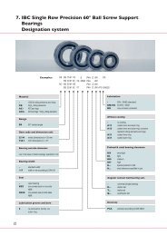
www.gmn.deGMNBearing designationExampleMaterial - Bearings made of bearing steel have no designationN Bearings made of high nitrogen steels, special material (on request)HY Balls and rings made of different materials (HYBRID <strong>bearings</strong>)HY SM ASeries S Standard spindle <strong>bearings</strong>SM Standard spindle <strong>bearings</strong> for higher speedsKH Standard spindle <strong>bearings</strong> for higher speeds, with seal6008 2RZ CLubrication - StandardA Oil lubrication hole through outer ring on open side<strong>AB</strong> Oil lubrication hole through outer ring on closed sideL Oil lubrication hole through outer ring on open side,outer ring seal with O-ringsLB Oil lubrication hole through outer ring on closed sideouter ring seal with O-ringsAG Oil lubrication hole through outer ring on open sideBearing size 6008 Designation of dimension series and bore diameterSeal 2RZ Seal on both sides (for KH series)Nominal contact C 15°angle E 25°18° Special designCage TA Laminated phenolic resin cage guided in outer ringTXM Plastic cage guided in outer ring, <strong>ball</strong>-retainingGMN<strong>High</strong> <strong>precision</strong>spindle <strong>ball</strong> <strong>bearings</strong>Bearing dataBore diameter 5 to 120 mmBoundary dimensionsTA P4 RPrecision P4 Tolerance class P4 corresponds to P4S per DIN 628-6P2 Tolerance class P2A7 <strong>AB</strong>EC 7 per <strong>AB</strong>MA standards, corresponds to P4A9 <strong>AB</strong>EC 9 per <strong>AB</strong>MA standards, corresponds to P2HG GMN high <strong>precision</strong> per GMN specificationUP GMN ultra <strong>precision</strong> per GMN specification<strong>High</strong> point R Marks the highest point of radial runoutmarking(the greatest wall thickness) for inner and outer ringRi like R, but only for inner ringRa like R, but only for outer ringBall dataDimensionsAbutment dimensionsWeightContact angleLoad ratingD UL - L252Bearing sets D 2 <strong>bearings</strong>T 3 <strong>bearings</strong>Q 4 <strong>bearings</strong>Matching and UL Universal matching – light preloadpreload UM Universal matching – medium preloadUS Universal matching – heavy preloadUV Universal matching – preload per agreementB O arrangementF X arrangementT Tandem arrangementSpeed valuesPreload / axial rigidityLubrication - ungreasedL252 Lubricant identifier, e.g. Turmogrease HS L25220 13 21
www.gmn.de7 to 10 mmBoundary dimensions Balls Dimensions Abutment dimensions WeightContactangleLoad rating Speed value Preload/axial rigiditySpringpreloadDesignation d D B d m D W Z d 1 d 2 D 1 D 2 r 1,2 r 3,4r a max r b max d a , b min D a , b max d T m α 0 C C 0 C 0 HY n oil n grease F v C ax F v C ax F v C ax F f DesignationL M S7 mm7 mmS 619/7 C TA 7 17 5 12.0 2.381 11 10.0 13.6 14.1 0.3 0.3 0.3 0.1 9.0 15.0 10.9 0.005 15 1510 655 460 145000 110000 8 9 23 15 46 21 40 S 619/7 C TAS 607 C TA 7 19 6 13.0 3.175 10 10.7 15.8 16.5 0.3 0.3 0.3 0.1 9.5 16.5 12.1 0.007 15 2600 1170 820 125000 94000 12 11 40 20 80 30 70 S 607 C TASM 607 C TA 7 19 6 13.0 3.175 10 10.7 15.8 16.5 0.3 0.3 0.3 0.1 9.5 16.5 12.1 0.007 15 1920 675 475 150000 110000 10 10 30 15 60 21 60 SM 607 C TAS 627 C TA 7 22 7 14.5 3.969 9 11.8 17.6 18.6 0.3 0.3 0.3 0.15 10.0 19.0 13.4 0.013 15 3400 1460 1030 115000 86000 20 13 50 19 100 28 90 S 627 C TA8 mm8 mmS 619/8 C TA 8 19 6 13.5 3.175 10 10.7 15.9 16.5 0.3 0.3 0.3 0.1 10.0 17.0 12.2 0.007 15 2600 1170 820 125000 94000 12 12 35 19 70 27 70 S 619/8 C TAS 608 C TA 8 22 7 15.0 3.969 9 11.8 17.6 18.6 0.3 0.3 0.3 0.1 10.5 19.0 13.4 0.010 15 3400 1460 1030 115000 86000 17 12 50 20 100 28 90 S 608 C TASM 608 C TA 8 22 7 15.0 3.969 9 11.8 17.6 18.6 0.3 0.3 0.3 0.1 10.5 19.0 13.4 0.010 15 2700 980 685 136000 100000 13 10 40 16 80 22 85 SM 608 C TA9 mmS 619/9 C TA 9 20 6 14.5 3.175 11 12.4 17.2 17.9 0.3 0.2 0.3 0.1 11.5 18.0 13.7 0.007 15 2800 1330 940 115000 86000 12 13 40 21 75 29 759 mmS 619/9 C TAS 609 C TA 9 24 7 16.5 3.969 10 13.5 19.9 20.6 0.3 0.3 0.3 0.1 11.5 21.0 15.2 0.014 15 3750 1710 1200 102000 76000 20 14 60 24 120 35 100 S 609 C TASM 609 C TA 9 24 7 16.5 3.969 10 13.5 19.9 20.6 0.3 0.3 0.3 0.1 11.5 21.0 15.2 0.014 15 2950 1150 810 120000 90000 16 12 50 20 100 27 90 SM 609 C TAS 629 C TA 9 26 8 17.5 4.762 10 14.7 21.4 22.7 0.3 0.3 0.3 0.15 13.0 23.0 16.5 0.020 15 5450 2600 1830 94000 70000 30 19 80 30 160 42 140 S 629 C TA10 mm10 mmS 61800 C TA 10 19 5 14.5 2.381 13 12.8 16.2 16.9 0.3 0.2 0.3 0.15 12.0 17.0 13.6 0.005 15 1660 830 580 115000 86000 8 10 25 17 50 23 45 S 61800 C TAS 61800 E TA 10 19 5 14.5 2.381 13 12.8 16.2 16.9 0.3 0.2 0.3 0.15 12.0 17.0 13.6 0.005 25 1500 725 510 100000 75000 13 25 40 39 80 51 55 S 61800 E TAS 61900 C TA 10 22 6 16.0 3.175 11 13.6 17.8 18.8 0.3 0.3 0.3 0.1 12.5 19.5 14.7 0.010 15 2800 1360 960 110000 82000 12 13 40 21 75 29 75 S 61900 C TAS 61900 E TA 10 22 6 16.0 3.175 11 13.6 17.8 18.8 0.3 0.3 0.3 0.1 12.5 19.5 14.7 0.010 25 2700 1300 920 92000 69000 22 32 70 50 140 65 100 S 61900 E TASM 61900 C TA 10 22 6 16.0 3.175 11 13.6 17.8 18.8 0.3 0.3 0.3 0.1 12.5 19.5 14.7 0.010 15 2080 810 565 125000 94000 11 11 30 16 65 23 65 SM 61900 C TAKH 61900 C TA 10 22 6 16.0 2.381 14 13.6 13.3 17.8 18.5 0.3 0.3 0.3 0.1 12.5 19.5 14.5 0.010 17 1420 590 415 135000 100000 7 12 21 18 45 25 55 KH 61900 C TAKH 61900 E TA 10 22 6 16.0 2.381 14 13.6 13.3 17.8 18.5 0.3 0.3 0.3 0.1 12.5 19.5 14.5 0.010 25 1360 565 400 125000 94000 11 25 35 37 70 49 65 KH 61900 E TAS 6000 C TA 10 26 8 18.0 4.762 10 14.7 21.4 22.7 0.3 0.3 0.3 0.1 12.5 23.0 16.5 0.018 15 5450 2600 1830 95000 71000 25 17 80 30 160 43 140 S 6000 C TAS 6000 E TA 10 26 8 18.0 4.762 10 14.7 21.4 22.7 0.3 0.3 0.3 0.1 12.5 23.0 16.5 0.018 25 5250 2550 1760 80000 60000 45 42 130 65 260 87 195 S 6000 E TASM 6000 C TA 10 26 8 18.0 4.762 10 14.7 21.4 22.7 0.3 0.3 0.3 0.1 12.5 23.0 16.5 0.018 15 3950 1530 1070 111000 83000 18 13 60 22 110 29 120 SM 6000 C TAKH 6000 C TA 10 26 8 18.0 3.175 11 14.7 14.2 20.5 21.3 0.3 0.3 0.3 0.1 12.5 23.0 15.9 0.018 17 2020 780 550 125000 94000 10 12 30 19 60 26 75 KH 6000 C TAKH 6000 E TA 10 26 8 18.0 3.175 11 14.7 14.2 20.5 21.3 0.3 0.3 0.3 0.1 12.5 23.0 15.9 0.018 25 1950 750 530 110000 82000 16 26 50 39 100 51 95 KH 6000 E TAS 6200 C TA 10 30 9 20.0 5.556 10 16.0 24.5 25.5 0.6 0.6 0.6 0.3 14.5 25.5 18.3 0.030 15 7500 3750 2650 85000 64000 40 23 120 39 230 54 195 S 6200 C TAS 6200 E TA 10 30 9 20.0 5.556 10 16.0 24.5 25.5 0.6 0.6 0.6 0.3 14.5 25.5 18.3 0.030 25 7250 3600 2550 72000 54000 60 54 180 81 360 110 265 S 6200 E TA24 25
www.gmn.de12 to 15 mmBoundary dimensions Balls Dimensions Abutment dimensions WeightContactangleLoad rating Speed value Preload/axial rigiditySpringpreloadDesignation d D B d m D W Z d 1 d 2 D 1 D 2 r 1,2 r 3,4r a max r b max d a , b min D a , b max d T m α 0 C C 0 C 0 HY n oil n grease F v C ax F v C ax F v C ax F f DesignationL M S12 mm12 mmS 61801 C TA 12 21 5 16.5 2.381 15 14.6 18.0 18.6 0.3 0.2 0.3 0.15 14.0 19.0 15.4 0.006 15 1800 980 685 105000 79000 9 12 25 18 55 26 50 S 61801 C TAS 61801 E TA 12 21 5 16.5 2.381 15 14.6 18.0 18.6 0.3 0.2 0.3 0.15 14.0 19.0 15.4 0.006 25 1710 930 650 89000 67000 15 29 45 44 90 58 65 S 61801 E TAS 61901 C TA 12 24 6 18.0 3.175 13 15.4 19.6 20.6 0.3 0.3 0.3 0.1 14.5 21.5 16.5 0.011 15 3100 1660 1170 97000 73000 15 15 43 24 85 34 80 S 61901 C TAS 61901 E TA 12 24 6 18.0 3.175 13 15.4 19.6 20.6 0.3 0.3 0.3 0.1 14.5 21.5 16.5 0.011 25 2950 1580 1110 83000 62000 25 37 75 56 150 74 110 S 61901 E TASM 61901 C TA 12 24 6 18.0 3.175 13 15.4 19.6 20.6 0.3 0.3 0.3 0.1 14.5 21.5 16.5 0.011 15 2330 990 695 115000 86000 12 13 35 19 70 26 70 SM 61901 C TAKH 61901 C TA 12 24 6 18.0 2.381 15 15.4 15.1 19.6 20.3 0.3 0.3 0.3 0.1 14.5 21.5 16.3 0.011 17 1480 650 455 120000 90000 7 12 22 19 45 26 55 KH 61901 C TAKH 61901 E TA 12 24 6 18.0 2.381 15 15.4 15.1 19.6 20.3 0.3 0.3 0.3 0.1 14.5 21.5 16.3 0.011 25 1410 620 440 110000 82000 12 26 35 39 70 51 70 KH 61901 E TAS 6001 C TA 12 28 8 20.0 4.762 11 16.7 23.4 24.7 0.3 0.3 0.3 0.1 14.5 25.0 18.5 0.020 15 5900 3000 2100 85000 64000 30 20 90 33 180 48 155 S 6001 C TAS 6001 E TA 12 28 8 20.0 4.762 11 16.7 23.4 24.7 0.3 0.3 0.3 0.1 14.5 25.0 18.5 0.020 25 5650 2900 2020 72500 54000 50 47 140 70 280 95 205 S 6001 E TASM 6001 C TA 12 28 8 20.0 4.762 11 16.7 23.4 24.7 0.3 0.3 0.3 0.1 14.5 25.0 18.5 0.020 15 4300 1750 1230 100000 75000 22 15 65 24 130 33 130 SM 6001 C TAKH 6001 C TA 12 28 8 19.0 3.175 13 16.7 16.2 22.5 23.3 0.3 0.3 0.3 0.1 14.5 25.0 18.0 0.020 17 2260 950 670 110000 82000 11 15 35 22 70 30 85 KH 6001 C TAKH 6001 E TA 12 28 8 19.0 3.175 13 16.7 16.2 22.5 23.3 0.3 0.3 0.3 0.1 14.5 25.0 18.0 0.020 25 2180 920 645 100000 75000 18 30 55 45 110 59 105 KH 6001 E TAS 6201 C TA 12 32 10 22.0 5.953 10 18.3 26.0 27.9 0.6 0.6 0.6 0.3 16.5 27.5 20.5 0.037 15 8300 4150 2950 77000 58000 42 23 130 39 250 54 215 S 6201 C TAS 6201 E TA 12 32 10 22.0 5.953 10 18.3 26.0 27.9 0.6 0.6 0.6 0.3 16.5 27.5 20.5 0.037 25 8000 4050 2850 66000 49000 70 56 200 84 400 112 290 S 6201 E TA15 mm15 mmS 61802 C TA 15 24 5 19.5 2.381 17 17.8 21.2 21.8 0.3 0.2 0.3 0.15 17.0 22.0 18.6 0.007 15 1900 1150 810 87000 65000 10 13 30 21 60 29 50 S 61802 C TAS 61802 E TA 15 24 5 19.5 2.381 17 17.8 21.2 21.8 0.3 0.2 0.3 0.15 17.0 22.0 18.6 0.007 25 1790 1090 770 74000 55000 15 32 45 48 90 62 65 S 61802 E TAS 61902 C TA 15 28 7 21.5 3.969 13 18.7 24.3 25.4 0.3 0.3 0.3 0.1 17.5 25.5 20.2 0.015 15 4500 2450 1720 79000 59000 22 18 70 29 140 42 115 S 61902 C TAS 61902 E TA 15 28 7 21.5 3.969 13 18.7 24.3 25.4 0.3 0.3 0.3 0.1 17.5 25.5 20.2 0.015 25 4300 2330 1640 67000 50000 35 44 110 68 220 89 160 S 61902 E TASM 61902 C TA 15 28 7 21.5 3.969 13 18.7 24.3 25.4 0.3 0.3 0.3 0.1 17.5 25.5 20.2 0.015 15 3600 1560 1100 93000 70000 18 15 55 24 110 33 110 SM 61902 C TAKH 61902 C TA 15 28 7 21.5 2.778 16 18.7 18.3 23.9 24.5 0.3 0.3 0.3 0.1 17.5 25.5 19.9 0.015 17 2010 940 660 100000 75000 10 15 30 23 60 31 75 KH 61902 C TAKH 61902 E TA 15 28 7 21.5 2.778 16 18.7 18.3 23.9 24.5 0.3 0.3 0.3 0.1 17.5 25.5 19.9 0.015 25 1930 900 630 90000 67000 16 32 50 48 100 64 95 KH 61902 E TAS 6002 C TA 15 32 9 23.5 4.762 13 20.2 26.9 28.2 0.3 0.3 0.3 0.1 17.5 29.0 21.9 0.028 15 6650 3750 2650 72000 54000 32 22 100 38 200 55 170 S 6002 C TAS 6002 E TA 15 32 9 23.5 4.762 13 20.2 26.9 28.2 0.3 0.3 0.3 0.1 17.5 29.0 21.9 0.028 25 6350 3600 2550 62000 46000 55 54 160 82 320 110 235 S 6002 E TASM 6002 C TA 15 32 9 23.5 4.762 13 20.2 26.9 28.2 0.3 0.3 0.3 0.1 17.5 29.0 21.9 0.028 15 4900 2140 1510 85000 64000 22 17 75 28 150 38 150 SM 6002 C TAKH 6002 C TA 15 32 9 23.5 3.969 13 20.2 19.4 26.7 28.0 0.3 0.3 0.3 0.1 17.5 29.0 21.6 0.028 17 3400 1470 1040 92000 69000 17 18 50 27 100 36 125 KH 6002 C TAKH 6002 E TA 15 32 9 23.5 3.969 13 20.2 19.4 26.7 28.0 0.3 0.3 0.3 0.1 17.5 29.0 21.6 0.028 25 3300 1420 1000 83000 62000 30 39 80 55 160 72 160 KH 6002 E TAS 6202 C TA 15 35 11 25.0 5.953 11 21.1 29.0 31.3 0.6 0.3 0.6 0.3 19.5 30.5 23.4 0.044 15 9000 4850 3450 67000 50000 45 25 130 41 270 59 230 S 6202 C TAS 6202 E TA 15 35 11 25.0 5.953 11 21.1 29.0 31.3 0.6 0.3 0.6 0.3 19.5 30.5 23.4 0.044 25 8700 4700 3300 57000 43000 75 61 220 93 440 123 320 S 6202 E TA26 27
www.gmn.de25 to 30 mmBoundary dimensions Balls Dimensions Abutment dimensions WeightContactangleLoad rating Speed value Preload/axial rigiditySpringpreloadDesignation d D B d m D W Z d 1 d 2 D 1 D 2 r 1,2 r 3,4r a max r b max d a , b min D a , b max d T m α 0 C C 0 C 0 HY n oil n grease F v C ax F v C ax F v C ax F f DesignationL M S25 mm25 mmS 61805 C TA 25 37 7 31.0 3.175 19 28.9 33.1 34.1 0.3 0.3 0.3 0.15 28.0 34.0 29.9 0.021 15 3650 2750 1930 55000 41000 19 21 55 33 110 46 95 S 61805 C TAS 61805 E TA 25 37 7 31.0 3.175 19 28.9 33.1 34.1 0.3 0.3 0.3 0.15 28.0 34.0 29.9 0.021 25 3450 2600 1830 47000 35000 30 51 90 76 170 98 130 S 61805 E TAS 61905 C TA 25 42 9 33.5 4.762 17 30.6 37.4 38.7 0.3 0.3 0.3 0.15 28.0 38.5 32.4 0.041 15 7700 5400 3800 50000 37000 40 29 120 48 240 67 200 S 61905 C TAS 61905 E TA 25 42 9 33.5 4.762 17 30.6 37.4 38.7 0.3 0.3 0.3 0.15 28.0 38.5 32.4 0.041 25 7300 5100 3600 43000 32000 60 70 180 105 360 138 265 S 61905 E TASM 61905 C TA 25 42 9 33.5 4.762 17 30.6 37.4 38.7 0.3 0.3 0.3 0.15 28.0 38.5 32.4 0.041 15 5800 3150 2200 59000 44000 30 23 90 36 180 49 175 SM 61905 C TAKH 61905 C TA 25 42 9 33.5 3.969 19 30.6 30 37.2 38.5 0.3 0.3 0.3 0.15 28.0 38.5 32.1 0.041 17 4250 2330 1640 63000 47000 22 25 65 38 130 51 155 KH 61905 C TAKH 61905 E TA 25 42 9 33.5 3.969 19 30.6 30 37.2 38.5 0.3 0.3 0.3 0.15 28.0 38.5 32.1 0.041 25 4100 2220 1560 57000 43000 35 52 100 76 200 99 195 KH 61905 E TAS 6005 C TA 25 47 12 36.0 6.35 15 32.2 40.1 42.3 0.6 0.3 0.6 0.3 30.0 42.0 34.3 0.076 15 13400 9200 6500 47000 35000 70 38 200 65 400 95 345 S 6005 C TAS 6005 E TA 25 47 12 36.0 6.35 15 32.2 40.1 42.3 0.6 0.3 0.6 0.3 30.0 42.0 34.3 0.076 25 12700 8800 6200 40000 30000 110 88 320 135 640 180 465 S 6005 E TASM 6005 C TA 25 47 12 36.0 6.35 15 32.2 40.1 42.3 0.6 0.3 0.6 0.3 30.0 42.0 34.3 0.076 15 9200 4700 3300 55000 41000 50 28 140 43 280 59 280 SM 6005 C TAKH 6005 C TA 25 47 12 36.0 5.556 17 32.2 30.9 42.0 43.6 0.6 0.3 0.6 0.3 30.0 42.0 34.2 0.076 17 7400 3900 2750 59000 44000 35 30 110 47 220 63 265 KH 6005 C TAKH 6005 E TA 25 47 12 36.0 5.556 17 32.2 30.9 42.0 43.6 0.6 0.3 0.6 0.3 30.0 42.0 34.2 0.076 25 7100 3750 2650 53000 40000 60 65 180 96 360 125 340 KH 6005 E TAS 6205 C TA 25 52 15 38.5 7.938 13 34.0 44.1 46.9 1.0 0.6 1.0 0.6 31.0 46.0 36.8 0.128 15 19000 12600 8900 44000 33000 100 45 300 77 600 112 485 S 6205 C TAS 6205 E TA 25 52 15 38.5 7.938 13 34.0 44.1 46.9 1.0 0.6 1.0 0.6 31.0 46.0 36.8 0.128 25 18200 12000 8400 37000 27500 150 104 450 159 900 216 660 S 6205 E TA30 mm30 mmS 61806 C TA 30 42 7 36.0 3.175 22 34.1 38.3 39.3 0.3 0.3 0.3 0.15 33.0 39.0 35.1 0.025 15 3850 3250 2280 47000 35000 20 24 60 37 120 52 100 S 61806 C TAS 61806 E TA 30 42 7 36.0 3.175 22 34.1 38.3 39.3 0.3 0.3 0.3 0.15 33.0 39.0 35.1 0.025 25 3650 3100 2150 40000 30000 30 56 90 76 180 109 135 S 61806 E TAS 61906 C TA 30 47 9 38.5 4.762 18 35.1 41.9 43.2 0.3 0.3 0.3 0.15 33.0 43.5 36.8 0.047 15 7800 5850 4100 44000 33000 40 30 120 50 240 69 200 S 61906 C TAS 61906 E TA 30 47 9 38.5 4.762 18 35.1 41.9 43.2 0.3 0.3 0.3 0.15 33.0 43.5 36.8 0.047 25 7400 5550 3900 38000 28500 60 72 190 111 380 146 270 S 61906 E TASM 61906 C TA 30 47 9 38.5 4.762 18 35.1 41.9 43.2 0.3 0.3 0.3 0.15 33.0 43.5 36.8 0.047 15 5950 3400 2380 52000 39000 30 24 90 37 180 50 180 SM 61906 C TAKH 61906 C TA 30 47 9 38.5 3.969 22 35.1 35 41.7 43.0 0.3 0.3 0.3 0.15 33.0 43.5 36.5 0.047 17 4650 2750 1930 55000 41000 23 28 70 43 140 57 170 KH 61906 C TAKH 61906 E TA 30 47 9 38.5 3.969 22 35.1 35 41.7 43.0 0.3 0.3 0.3 0.15 33.0 43.5 36.5 0.047 25 4400 2650 1840 50000 37000 35 58 110 87 220 112 210 KH 61906 E TAS 6006 C TA 30 55 13 42.5 7.144 16 38.1 47.0 49.5 1.0 0.6 1.0 0.3 36.0 49.0 40.5 0.112 15 16500 11900 8400 40000 30000 85 43 250 72 500 105 425 S 6006 C TAS 6006 E TA 30 55 13 42.5 7.144 16 38.1 47.0 49.5 1.0 0.6 1.0 0.3 36.0 49.0 40.5 0.112 25 15700 11400 8000 34000 25500 130 98 400 150 800 205 570 S 6006 E TASM 6006 C TA 30 55 13 42.5 7.144 16 38.1 47.0 49.5 1.0 0.6 1.0 0.3 36.0 49.0 40.5 0.112 15 11900 6450 4550 47000 35000 60 32 180 50 360 69 360 SM 6006 C TAKH 6006 C TA 30 55 13 42.5 5.556 20 38.1 37 47.9 49.5 1.0 0.6 1.0 0.3 36.0 49.0 40.1 0.112 17 8200 4700 3350 50000 37000 40 35 120 54 250 73 295 KH 6006 C TAKH 6006 E TA 30 55 13 42.5 5.556 20 38.1 37 47.9 49.5 1.0 0.6 1.0 0.3 36.0 49.0 40.1 0.112 25 7800 4500 3200 46000 34000 65 74 200 111 390 143 375 KH 6006 E TAS 6206 C TA 30 62 16 46.0 9.525 13 40.4 52.1 55.4 1.0 0.6 1.0 0.6 36.0 55.0 43.6 0.199 15 25000 16700 11800 37000 27500 130 49 380 82 760 117 640 S 6206 C TAS 6206 E TA 30 62 16 46.0 9.525 13 40.4 52.1 55.4 1.0 0.6 1.0 0.6 36.0 55.0 43.6 0.199 25 24000 16100 11300 32000 24000 200 117 600 177 1200 239 880 S 6206 E TA30 31
www.gmn.de45 to 50 mmBoundary dimensions Balls Dimensions Abutment dimensions WeightContactangleLoad rating Speed value Preload/axial rigiditySpringpreloadDesignation d D B d m D W Z d 1 d 2 D 1 D 2 r 1,2 r 3,4r a max r b max d a , b min D a , b max d T m α 0 C C 0 C 0 HY n oil n grease F v C ax F v C ax F v C ax F f DesignationL M S45 mm45 mmS 61909 C TA 45 68 12 56.5 6.35 20 52.3 60.7 62.7 0.6 0.3 0.6 0.15 50.0 63.5 54.5 0.128 15 15200 13600 9600 30000 22500 80 49 230 79 460 112 390 S 61909 C TAS 61909 E TA 45 68 12 56.5 6.35 20 52.3 60.7 62.7 0.6 0.3 0.6 0.15 50.0 63.5 54.5 0.128 25 14300 12900 9100 25500 19000 120 115 360 173 720 232 520 S 61909 E TASM 61909 C TA 45 68 12 56.5 6.35 20 52.3 60.7 62.7 0.6 0.3 0.6 0.15 50.0 63.5 54.5 0.128 17 10600 6800 4800 35000 26000 55 42 160 64 320 85 365 SM 61909 C TAKH 61909 C TA 45 68 12 56.5 4.762 28 52.3 50.8 60.7 62.2 0.6 0.3 0.6 0.15 50.0 63.5 53.8 0.128 17 7300 5150 3600 38000 28500 35 40 110 61 220 81 265 KH 61909 C TAKH 61909 E TA 45 68 12 56.5 4.762 28 52.3 50.8 60.7 62.2 0.6 0.3 0.6 0.15 50.0 63.5 53.8 0.128 25 6950 4900 3450 34000 25500 60 86 170 124 350 162 335 KH 61909 E TAS 6009 C TA 45 75 16 60.0 8.731 18 54.7 65.0 68.6 1.0 0.6 1.0 0.3 51.0 69.0 57.6 0.238 15 27000 22600 15900 28000 21000 130 60 400 105 800 150 690 S 6009 C TAS 6009 E TA 45 75 16 60.0 8.731 18 54.7 65.0 68.6 1.0 0.6 1.0 0.3 51.0 69.0 57.6 0.238 25 26000 21500 15100 24000 18000 210 140 650 220 1300 300 950 S 6009 E TASM 6009 C TA 45 75 16 60.0 8.731 18 54.7 65.0 68.6 1.0 0.6 1.0 0.3 51.0 69.0 57.6 0.238 15 18500 11400 8000 33000 24500 90 44 275 69 550 93 560 SM 6009 C TAKH 6009 C TA 45 75 16 60.0 6.35 22 54.7 53 65.6 67.8 1.0 0.6 1.0 0.3 51.0 69.0 56.9 0.238 17 10800 6950 4900 36000 27000 55 44 160 65 330 88 390 KH 6009 C TAKH 6009 E TA 45 75 16 60.0 6.35 22 54.7 53 65.6 67.8 1.0 0.6 1.0 0.3 51.0 69.0 56.9 0.238 25 10300 6650 4700 32000 24000 90 92 260 135 520 175 490 KH 6009 E TAS 6209 C TA 45 85 19 65.0 12.7 14 57.4 72.5 77.5 1.1 0.6 1.0 0.6 53.0 77.0 61.7 0.416 15 45500 33500 23500 26000 19500 230 71 700 119 1400 171 1170 S 6209 C TAS 6209 E TA 45 85 19 65.0 12.7 14 57.4 72.5 77.5 1.1 0.6 1.0 0.6 53.0 77.0 61.7 0.416 25 43500 32500 22600 22500 17000 370 169 1100 257 2200 346 1580 S 6209 E TA50 mm50 mmS 61910 C TA 50 72 12 61.0 6.35 21 56.8 65.2 67.2 0.6 0.3 0.6 0.15 55.0 67.5 58.9 0.129 15 15400 14500 10200 28000 21000 80 50 230 81 460 115 395 S 61910 C TAS 61910 E TA 50 72 12 61.0 6.35 21 56.8 65.2 67.2 0.6 0.3 0.6 0.15 55.0 67.5 58.9 0.129 25 14500 13700 9700 24000 18000 120 119 370 180 740 241 530 S 61910 E TASM 61910 C TA 50 72 12 61.0 6.35 21 56.8 65.2 67.2 0.6 0.3 0.6 0.15 55.0 67.5 58.9 0.129 17 10900 7200 5100 33000 24500 55 44 170 67 330 89 375 SM 61910 C TAKH 61910 C TA 50 72 12 61.0 4.762 30 56.8 55.3 65.2 66.7 0.6 0.3 0.6 0.15 55.0 67.5 58.3 0.129 17 7500 5550 3900 35000 26000 40 44 110 64 230 86 270 KH 61910 C TAKH 61910 E TA 50 72 12 61.0 4.762 30 56.8 55.3 65.2 66.7 0.6 0.3 0.6 0.15 55.0 67.5 58.3 0.129 25 7150 5300 3700 32000 24000 60 90 180 132 360 171 340 KH 61910 E TAS 6010 C TA 50 80 16 65.0 8.731 19 59.7 70.0 73.6 1.0 0.6 1.0 0.3 56.0 74.0 62.5 0.256 15 28000 24300 17100,0 26000 19500 140 64 420 110 840 160 715 S 6010 C TAS 6010 E TA 50 80 16 65.0 8.731 19 59.7 70.0 73.6 1.0 0.6 1.0 0.3 56.0 74.0 62.5 0.256 25 26500 23100 16300 22000 16500 220 145 670 230 1330 310 970 S 6010 E TASM 6010 C TA 50 80 16 65.0 8.731 19 59.7 70.0 73.6 1.0 0.6 1.0 0.3 56.0 74.0 62.5 0.256 15 19000 12300 8600 31000 23000 100 47 290 72 580 99 570 SM 6010 C TAKH 6010 C TA 50 80 16 65.0 6.35 25 59.7 58 70.7 73.1 1.0 0.6 1.0 0.3 56.0 74.0 61.9 0.256 17 11600 8000 5650 33000 24500 60 49 180 74 350 98 415 KH 6010 C TAKH 6010 E TA 50 80 16 65.0 6.35 25 59.7 58 70.7 73.1 1.0 0.6 1.0 0.3 56.0 74.0 61.9 0.256 25 11100 7600 5350 30000 22500 90 100 280 150 560 194 530 KH 6010 E TAS 6210 C TA 50 90 20 70.0 12.7 15 62.5 76.9 82.7 1.1 0.6 1.0 0.6 58.0 82.0 66.7 0.486 15 47500 37000 26000 24500 18500 240 75 720 125 1440 178 1220 S 6210 C TAS 6210 E TA 50 90 20 70.0 12.7 15 62.5 76.9 82.7 1.1 0.6 1.0 0.6 58.0 82.0 66.7 0.486 25 45000 35500 24700 20500 15500 380 177 1140 271 2280 363 1640 S 6210 E TA34 35
www.gmn.de55 to 60 mmBoundary dimensions Balls Dimensions Abutment dimensions WeightContactangleLoad rating Speed value Preload/axial rigiditySpringpreloadDesignation d D B d m D W Z d 1 d 2 D 1 D 2 r 1,2 r 3,4r a max r b max d a , b min D a , b max d T m α 0 C C 0 C 0 HY n oil n grease F v C ax F v C ax F v C ax F f DesignationL M S55 mm55 mmS 61911 C TA 55 80 13 67.5 7.144 21 63.1 71.9 74.5 1.0 0.3 0.6 0.3 60.0 75.0 65.4 0.181 15 18400 17100 12100 25000 18500 90 52 280 87 560 122 470 S 61911 C TAS 61911 E TA 55 80 13 67.5 7.144 21 63.1 71.9 74.5 1.0 0.3 0.6 0.3 60.0 75.0 65.4 0.181 25 17400 16200 11400 21500 16000 150 130 440 193 880 257 635 S 61911 E TASM 61911 C TA 55 80 13 67.5 7.144 21 63.1 71.9 74.5 1.0 0.3 0.6 0.3 60.0 75.0 65.4 0.181 17 13600 9400 6600 29500 22000 70 49 210 75 420 100 465 SM 61911 C TAKH 61911 C TA 55 80 13 67.5 5.556 30 63.1 61.8 72.9 74.5 1.0 0.3 0.6 0.3 60.0 75.0 65.0 0.181 17 10000 7500 5250 31000 23000 50 50 150 75 300 99 360 KH 61911 C TAKH 61911 E TA 55 80 13 67.5 5.556 30 63.1 61.8 72.9 74.5 1.0 0.3 0.6 0.3 60.0 75.0 65.0 0.181 25 9600 7150 5050 28500 21500 80 104 240 154 480 199 460 KH 61911 E TAS 6011 C TA 55 90 18 72.5 9.525 20 66.8 78.2 81.9 1.1 1.0 1.1 0.6 62.0 83.0 69.8 0.374 15 32500 29500 20500 23500 17500 160 69 490 115 980 163 830 S 6011 C TAS 6011 E TA 55 90 18 72.5 9.525 20 66.8 78.2 81.9 1.1 1.0 1.1 0.6 62.0 83.0 69.8 0.374 25 30500 28000 19400 20000 15000 260 167 770 253 1540 337 1110 S 6011 E TASM 6011 C TA 55 90 18 72.5 9.525 20 66.8 78.2 81.9 1.1 1.0 1.1 0.6 62.0 83.0 69.8 0.374 15 23100 15500 10900 27500 20500 115 52 350 81 700 110 695 SM 6011 C TAKH 6011 C TA 55 90 18 72.5 7.938 23 66.8 65.6 79.2 82.4 1.1 1.0 1.1 0.6 62.0 83.0 69.3 0.374 17 16700 11400 8000 29500 22000 80 55 250 84 500 111 600 KH 6011 C TAKH 6011 E TA 55 90 18 72.5 7.938 23 66.8 65.6 79.2 82.4 1.1 1.0 1.1 0.6 62.0 83.0 69.3 0.374 25 15900 10800 7600 26500 20000 130 115 400 172 800 223 760 KH 6011 E TAS 6211 C TA 55 100 21 77.5 14.288 15 69.0 85.8 91.6 1.5 1.0 1.5 1.0 64.0 91.0 73.8 0.621 15 58000 46000 32500 22000 16500 300 83 900 139 1800 199 1480 S 6211 C TAS 6211 E TA 55 100 21 77.5 14.288 15 69.0 85.8 91.6 1.5 1.0 1.5 1.0 64.0 91.0 73.8 0.621 25 55500 44000 31000 18500 14000 470 198 1400 300 2800 404 2020 S 6211 E TA60 mm60 mmS 61912 C TA 60 85 13 72.5 7.144 23 68.1 76.9 79.5 1.0 0.3 0.6 0.3 65.0 80.0 70.4 0.195 15 19200 19000 13300 23500 17500 100 58 300 94 600 132 490 S 61912 C TAS 61912 E TA 60 85 13 72.5 7.144 23 68.1 76.9 79.5 1.0 0.3 0.6 0.3 65.0 80.0 70.4 0.195 25 18100 17900 12600 20000 15000 150 137 460 208 920 276 660 S 61912 E TASM 61912 C TA 60 85 13 72.5 7.144 23 68.1 76.9 79.5 1.0 0.3 0.6 0.3 65.0 80.0 70.4 0.195 19 14100 10300 7200 27500 20500 70 61 220 93 430 122 540 SM 61912 C TAKH 61912 C TA 60 85 13 72.5 5.556 32 68.1 66.8 77.9 79.5 1.0 0.3 0.6 0.3 65.0 80.0 70.0 0.195 17 10300 8100 5650 29500 22000 50 52 160 80 310 104 370 KH 61912 C TAKH 61912 E TA 60 85 13 72.5 5.556 32 68.1 66.8 77.9 79.5 1.0 0.3 0.6 0.3 65.0 80.0 70.0 0.195 25 9800 7700 5400 26500 20000 80 109 240 161 490 209 470 KH 61912 E TAS 6012 C TA 60 95 18 77.5 9.525 22 71.9 83.2 87.0 1.1 1.0 1.1 0.6 67.0 88.0 74.9 0.406 15 34000 32500 22800 22000 16500 170 75 515 124 1030 175 870 S 6012 C TAS 6012 E TA 60 95 18 77.5 9.525 22 71.9 83.2 87.0 1.1 1.0 1.1 0.6 67.0 88.0 74.9 0.406 25 32000 31000 21600 18500 14000 270 180 810 274 1620 364 1160 S 6012 E TASM 6012 C TA 60 95 18 77.5 9.525 22 71.9 83.2 87.0 1.1 1.0 1.1 0.6 67.0 88.0 74.9 0.406 15 24500 17400 12200 26000 19500 125 56 375 83 750 120 740 SM 6012 C TAKH 6012 C TA 60 95 18 77.5 7.938 24 71.9 70.7 84.2 87.4 1.1 1.0 1.1 0.6 67.0 88.0 74.4 0.406 17 17000 11900 8400 27500 20500 90 59 260 87 510 115 610 KH 6012 C TAKH 6012 E TA 60 95 18 77.5 7.938 24 71.9 70.7 84.2 87.4 1.1 1.0 1.1 0.6 67.0 88.0 74.4 0.406 25 16200 11400 8000 25000 18500 140 122 400 177 800 229 770 KH 6012 E TAS 6212 C TA 60 110 22 85.0 15.875 15 76.0 95.5 101.4 1.5 1.0 1.5 1.0 70.0 101.0 81.5 0.795 15 70000 56500 40000 20000 15000 350 90 1000 146 2100 213 1790 S 6212 C TAS 6212 E TA 60 110 22 85.0 15.875 15 76.0 95.5 101.4 1.5 1.0 1.5 1.0 70.0 101.0 81.5 0.795 25 66500 54000 38000 17000 12500 560 216 1700 333 3400 443 2420 S 6212 E TA36 37
www.gmn.de65 to 75 mmBoundary dimensions Balls Dimensions Abutment dimensions WeightContactangleLoad rating Speed value Preload/axial rigiditySpringpreloadDesignation d D B d m D W Z d 1 d 2 D 1 D 2 r 1,2 r 3,4r a max r b max d a , b min D a , b max d T m α 0 C C 0 C 0 HY n oil n grease F v C ax F v C ax F v C ax F f DesignationL M S65 mm65 mmS 61913 C TA 65 90 13 77.5 7.144 24 73.1 81.9 84.5 1.0 0.3 0.6 0.3 70.0 85.0 75.4 0.207 15 19500 20000 14000 22000 16500 100 59 300 96 600 135 500 S 61913 C TAS 61913 E TA 65 90 13 77.5 7.144 24 73.1 81.9 84.5 1.0 0.3 0.6 0.3 70.0 85.0 75.4 0.207 25 18300 18900 13300 18500 14000 160 144 470 215 940 286 665 S 61913 E TASM 61913 C TA 65 90 13 77.5 7.144 24 73.1 81.9 84.5 1.0 0.3 0.6 0.3 70.0 85.0 75.4 0.207 19 14400 10800 7600 26000 19500 75 64 220 96 440 126 550 SM 61913 C TAKH 61913 C TA 65 90 13 77.5 5.556 34 73.1 71.8 82.9 84.5 1.0 0.3 0.6 0.3 70.0 85.0 75.0 0.207 17 10600 8600 6050 27500 20500 55 56 160 83 320 110 380 KH 61913 C TAKH 61913 E TA 65 90 13 77.5 5.556 34 73.1 71.8 82.9 84.5 1.0 0.3 0.6 0.3 70.0 85.0 75.0 0.207 25 10100 8200 5800 25000 18500 80 113 250 169 500 219 480 KH 61913 E TAS 6013 C TA 65 100 18 82.5 9.525 23 76.9 88.2 92.0 1.1 1.0 1.1 0.6 72.0 93.0 79.9 0.431 15 34500 34500 24100 20500 15500 175 78 525 128 1050 181 880 S 6013 C TAS 6013 E TA 65 100 18 82.5 9.525 23 76.9 88.2 92.0 1.1 1.0 1.1 0.6 72.0 93.0 79.9 0.431 25 32500 32500 22900 17500 13000 275 187 825 284 1650 376 1180 S 6013 E TASM 6013 C TA 65 100 18 82.5 9.525 23 76.9 88.2 92.0 1.1 1.0 1.1 0.6 72.0 93.0 79.9 0.431 15 25000 18400 13000 24000 18000 130 58 380 91 760 123 760 SM 6013 C TAKH 6013 C TA 65 100 18 82.5 7.938 25 76.9 75.7 89.2 92.4 1.1 1.0 1.1 0.6 72.0 93.0 79.3 0.431 17 17300 12500 8800 26000 19500 90 60 260 90 520 119 620 KH 6013 C TAKH 6013 E TA 65 100 18 82.5 7.938 25 76.9 75.7 89.2 92.4 1.1 1.0 1.1 0.6 72.0 93.0 79.3 0.431 25 16500 11900 8400 23500 17500 140 125 410 182 800 235 790 KH 6013 E TAS 6213 C TA 65 120 23 92.5 15.875 16 82.8 102.3 108.5 1.5 1.1 1.5 1.1 75.0 110.0 88.3 1.008 15 72500 61500 43500 18500 14000 370 96 1110 158 2220 225 1850 S 6213 C TAS 6213 E TA 65 120 23 92.5 15.875 16 82.8 102.3 108.5 1.5 1.1 1.5 1.1 75.0 110.0 88.3 1.008 25 69000 59000 41500 15500 11500 590 228 1760 347 3520 462 2550 S 6213 E TA70 mm70 mmS 61914 C TA 70 100 16 85 7.938 24 80.1 89.9 92.7 1.0 0.3 0.6 0.3 76.0 94.5 82.6 0.346 15 24400 26000 18200 20000 15000 130 69 370 111 740 156 625 S 61914 C TAS 61914 E TA 70 100 16 85 7.938 24 80.1 89.9 92.7 1.0 0.3 0.6 0.3 76.0 94.5 82.6 0.346 25 23000 24500 17300 17000 12500 200 165 590 247 1180 329 840 S 61914 E TASM 61914 C TA 70 100 16 85 7.938 24 80.1 89.9 92.7 1.0 0.3 0.6 0.3 76.0 94.5 82.6 0.346 19 17300 13000 9200 23500 17500 90 71 260 105 530 139 660 SM 61914 C TAKH 61914 C TA 70 100 16 85 6.35 32 80.1 78.5 91.3 93.4 1.0 0.3 0.6 0.3 76.0 94.5 82.3 0.346 17 13000 10600 7400 25000 18500 65 59 200 89 390 118 465 KH 61914 C TAKH 61914 E TA 70 100 16 85 6.35 32 80.1 78.5 91.3 93.4 1.0 0.3 0.6 0.3 76.0 94.5 82.3 0.346 25 12400 10100 7050 22500 17000 100 122 310 182 620 235 590 KH 61914 E TAS 6014 C TA 70 110 20 90 11.906 21 82.6 97.4 101.7 1.1 1.0 1.1 0.6 77.0 102.0 86.6 0.593 15 48500 46000 32500 19000 14000 240 85 700 140 1400 200 1240 S 6014 C TAS6014 E TA 70 110 20 90 11.906 21 82.6 97.4 101.7 1.1 1.0 1.1 0.6 77.0 102.0 86.6 0.593 25 46000 43500 30500 16000 12000 400 200 1200 310 2400 420 1670 S 6014 E TASM 6014 C TA 70 110 20 90 11.906 21 82.6 97.4 101.7 1.1 1.0 1.1 0.6 77.0 102.0 86.6 0.593 15 35500 25500 17800 22000 16500 180 66 500 99 1000 134 1070 SM 6014 C TAKH 6014 C TA 70 110 20 90 9.525 24 82.6 81.1 96.7 100.8 1.1 1.0 1.1 0.6 77.0 102.0 85.7 0.593 17 23700 17200 12100 24000 18000 120 68 360 104 720 137 850 KH 6014 C TAKH 6014 E TA 70 110 20 90 9.525 24 82.6 81.1 96.7 100.8 1.1 1.0 1.1 0.6 77.0 102.0 85.7 0.593 25 22700 16400 11500 21500 16000 190 143 570 211 1150 274 1080 KH 6014 E TA75 mm75 mmS 61915 C TA 75 105 16 90 8.731 25 84.7 95.3 98.8 0.6 0.3 0.6 0.3 81.0 99.5 87.5 0.35 15 29500 31000 21600 19000 14000 150 75 440 120 890 169 760 S 61915 C TAS 61915 E TA 75 105 16 90 8.731 25 84.7 95.3 98.8 0.6 0.3 0.6 0.3 81.0 99.5 87.5 0.35 25 27500 29500 20500 16000 12000 230 178 700 270 1400 360 1000 S 61915 E TASM 61915 C TA 75 105 16 90 8.731 25 84.7 95.3 98.8 0.6 0.3 0.6 0.3 81.0 99.5 87.5 0.35 19 20800 16000 11300 22000 16500 110 78 320 116 640 153 800 SM 61915 C TAS 6015 C TA 75 115 20 95 11.906 22 87.8 102.2 107 1.1 0.6 1.1 0.6 82.0 107.0 91.7 0.64 15 49500 48500 34000 18000 13500 250 91 760 148 1510 208 1270 S 6015 C TAS 6015 E TA 75 115 20 95 11.906 22 87.8 102.2 107 1.1 0.6 1.1 0.6 82.0 107.0 91.7 0.64 25 47000 46000 32500 15500 11500 400 219 1190 330 2380 440 1710 S 6015 E TASM 6015 C TA 75 115 20 95 11.906 22 87.8 102.2 107 1.1 0.6 1.1 0.6 82.0 107.0 91.7 0.64 17 36000 26500 18700 21000 15500 180 82 550 126 1100 167 1230 SM 6015 C TA38 39
www.gmn.de80 to 95 mmBoundary dimensions Balls Dimensions Abutment dimensions WeightContactangleLoad rating Speed value Preload/axial rigiditySpringpreloadDesignation d D B d m D W Z d 1 d 2 D 1 D 2 r 1,2 r 3,4r a max r b max d a , b min D a , b max d T m α 0 C C 0 C 0 HY n oil n grease F v C ax F v C ax F v C ax F f DesignationL M S80 mm80 mmS 61916 C TA 80 110 16 95 9.525 25 89.4 100.8 104.6 0.6 0.3 0.6 0.3 86 104 92.4 0.37 15 35500 38500 27000 18000 13500 180 84 540 136 1080 192 910 S 61916 C TAS 61916 E TA 80 110 16 95 9.525 25 89.4 100.8 104.6 0.6 0.3 0.6 0.3 86 104 92.4 0.37 25 33500 36500 25500 15500 11500 280 199 840 305 1680 400 1220 S 61916 E TASM 61916 C TA 80 110 16 95 9.525 25 89.4 100.8 104.6 0.6 0.3 0.6 0.3 86 104 92.4 0.37 19 25500 20100 14200 21000 15500 130 88 390 133 780 175 970 SM 61916 C TAS 6016 C TA 80 125 22 102.5 13.494 20 94.3 110.7 116.1 1.1 0.6 1.1 0.6 88 117 98.7 0.84 15 60000 58000 41000 16500 12500 310 98 920 159 1830 224 1540 S 6016 C TAS 6016 E TA 80 125 22 102.5 13.494 20 94.3 110.7 116.1 1.1 0.6 1.1 0.6 88 117 98.7 0.84 25 57500 56500 40000 14000 10500 490 235 1470 360 2930 475 2090 S 6016 E TASM 6016 C TA 80 125 22 102.5 13.494 20 94.3 110.7 116.1 1.1 0.6 1.1 0.6 88 117 98.7 0.84 17 43000 31000 21600 19500 14500 220 87 650 131 1300 174 1470 SM 6016 C TA85 mm85 mmS 61917 C TA 85 120 18 102.5 10.319 25 96.2 108.8 112.9 0.6 0.6 0.6 0.6 92 114 99.5 0.54 15 40000 43000 30500 16500 12500 200 87 610 142 1220 198 1020 S 61917 C TAS 61917 E TA 85 120 18 102.5 10.319 25 96.2 108.8 112.9 0.6 0.6 0.6 0.6 92 114 99.5 0.54 25 37500 40500 28500 14000 10500 320 210 960 320 1910 420 1360 S 61917 E TASM 61917 C TA 85 120 18 102.5 10.319 25 96.2 108.8 112.9 0.6 0.6 0.6 0.6 92 114 99.5 0.54 19 29500 23200 16300 19500 14500 150 94 440 140 890 185 1130 SM 61917 C TAS 6017 C TA 85 130 22 107.5 13.494 21 99.3 115.7 121.1 1.1 0.6 1.1 0.6 93 122 103.7 0.89 15 61500 61500 43500 16000 12000 310 101 940 165 1880 233 1570 S 6017 C TAS 6017 E TA 85 130 22 107.5 13.494 21 99.3 115.7 121.1 1.1 0.6 1.1 0.6 93 122 103.7 0.89 25 59000 60000 42000 13500 10000 500 245 1500 370 3000 495 2140 S 6017 E TASM 6017 C TA 85 130 22 107.5 13.494 21 99.3 115.7 121.1 1.1 0.6 1.1 0.6 93 122 103.7 0.89 17 44000 32500 22900 18500 14000 220 89 670 137 1340 182 1500 SM 6017 C TA90 mm90 mmS 61918 C TA 90 125 18 107.5 10.319 26 101.2 113.8 117.9 0.6 0.6 0.6 0.6 97 119 104.5 0.56 15 40500 45000 31500 16000 12000 210 91 620 146 1240 204 1040 S 61918 C TAS 61918 E TA 90 125 18 107.5 10.319 26 101.2 113.8 117.9 0.6 0.6 0.6 0.6 97 119 104.5 0.56 25 38500 42500 30000 13500 10000 320 216 970 330 1940 435 1400 S 61918 E TASM 61918 C TA 90 125 18 107.5 10.319 26 101.2 113.8 117.9 0.6 0.6 0.6 0.6 97 119 104.5 0.56 19 30000 24200 17000 18500 14000 150 97 450 145 910 191 1140 SM 61918 C TAS 6018 C TA 90 140 24 115 15.081 20 105.8 124.2 130.1 1.5 0.6 1.5 0.6 100 131 110.7 1.15 15 74500 74000 52000 15000 11000 380 110 1130 179 2270 255 1900 S 6018 C TAS 6018 E TA 90 140 24 115 15.081 20 105.8 124.2 130.1 1.5 0.6 1.5 0.6 100 131 110.7 1.15 25 70500 70000 49500 12500 9400 600 265 1790 400 3570 525 2600 S 6018 E TASM 6018 C TA 90 140 24 115 15.081 20 105.8 124.2 130.1 1.5 0.6 1.5 0.6 100 131 110.7 1.15 17 52000 38500 27000 17500 13000 270 96 800 146 1590 194 1770 SM 6018 C TA95 mm95 mmS 61919 C TA 95 130 18 112.5 10.319 27 106.2 118.8 122.9 0.6 0.6 0.6 0.6 102 124 109.5 0.59 15 41000 47000 33000 15000 11000 210 93 630 150 1250 209 1050 S 61919 C TAS 61919 E TA 95 130 18 112.5 10.319 27 106.2 118.8 122.9 0.6 0.6 0.6 0.6 102 124 109.5 0.59 25 39000 44500 31500 13000 9800 330 223 980 335 1970 445 1420 S 61919 E TASM 61919 C TA 95 130 18 112.5 10.319 27 106.2 118.8 122.9 0.6 0.6 0.6 0.6 102 124 109.5 0.59 19 30500 25500 17800 18000 13500 150 99 460 150 920 196 1160 SM 61919 C TAS 6019 C TA 95 145 24 120 15.081 21 110.8 129.2 135.1 1.5 0.6 1.5 0.6 105 136 115.7 1.20 15 77000 79000 55000 14000 10500 390 114 1160 186 2330 265 1970 S 6019 C TAS 6019 E TA 95 145 24 120 15.081 21 110.8 129.2 135.1 1.5 0.6 1.5 0.6 105 136 115.7 1.20 25 72000 74500 52500 12000 9000 610 275 1830 415 3660 550 2650 S 6019 E TASM 6019 C TA 95 145 24 120 15.081 21 110.8 129.2 135.1 1.5 0.6 1.5 0.6 105 136 115.7 1.20 17 53500 41000 28500 16500 12500 270 99 820 152 1640 202 1820 SM 6019 C TA40 41
www.gmn.de100 to 120 mmBoundary dimensions Balls Dimensions Abutment dimensions WeightContactangleLoad rating Speed value Preload/axial rigiditySpringpreloadDesignation d D B d m D W Z d 1 d 2 D 1 D 2 r 1,2 r 3,4r a max r b max d a , b min D a , b max d T m α 0 C C 0 C 0 HY n oil n grease F v C ax F v C ax F v C ax F f DesignationL M S100 mm100 mmS 61920 C TA 100 140 20 120 11.906 25 112.8 127.2 132.0 0.6 0.6 0.6 0.6 107 133 116.5 0.80 15 51500 57000 40500 14000 10500 260 100 790 162 1570 226 1320 S 61920 C TAS 61920 E TA 100 140 20 120 11.906 25 112.8 127.2 132.0 0.6 0.6 0.6 0.6 107 133 116.5 0.80 25 48500 54000 38000 12000 9000 410 240 1230 365 2470 480 1760 S 61920 E TASM 61920 C TA 100 140 20 120 11.906 25 112.8 127.2 132.0 0.6 0.6 0.6 0.6 107 133 116.5 0.80 19 37500 31000 21700 16500 12500 190 107 570 160 1150 211 1430 SM 61920 C TAS 6020 C TA 100 150 24 125 15.081 22 115.8 134.2 140.1 1.5 0.6 1.5 0.6 110 141 120.7 1.25 15 78000 83000 58000 13500 10000 400 118 1190 193 2380 275 1990 S 6020 C TAS 6020 E TA 100 150 24 125 15.081 22 115.8 134.2 140.1 1.5 0.6 1.5 0.6 110 141 120.7 1.25 25 74000 79000 55000 11500 8600 630 285 1880 430 3750 570 2700 S 6020 E TASM 6020 C TA 100 150 24 125 15.081 22 115.8 134.2 140.1 1.5 0.6 1.5 0.6 110 141 120.7 1.25 17 55000 43000 30500 16000 12000 280 104 840 158 1680 210 1880 SM 6020 C TA105 mm105 mmS 61921 C TA 105 145 20 125 11.906 26 117.8 132.2 137.0 0.6 0.6 0.6 0.6 112 138 121.5 0.83 15 52500 60000 42000 13500 10000 270 103 800 166 1600 232 1340 S 61921 C TAS 61921 E TA 105 145 20 125 11.906 26 117.8 132.2 137.0 0.6 0.6 0.6 0.6 112 138 121.5 0.83 25 49500 56500 40000 11500 8600 420 248 1250 375 2510 495 1800 S 61921 E TASM 61921 C TA 105 145 20 125 11.906 26 117.8 132.2 137.0 0.6 0.6 0.6 0.6 112 138 121.5 0.83 19 38500 32500 22700 16000 12000 200 112 590 166 1170 218 1470 SM 61921 C TAS 6021 C TA 105 160 26 132.5 15.875 22 122.8 142.2 148.4 2.0 1.0 2.0 1.0 116 150 127.9 1.59 15 86000 92000 64500 13000 9800 440 125 1310 203 2610 285 2200 S 6021 C TAS 6021 E TA 105 160 26 132.5 15.875 22 122.8 142.2 148.4 2.0 1.0 2.0 1.0 116 150 127.9 1.59 25 81000 87000 61500 11000 8200 690 300 2060 450 4120 595 2950 S 6021 E TASM 6021 C TA 105 160 26 132.5 15.875 22 122.8 142.2 148.4 2.0 1.0 2.0 1.0 116 150 127.9 1.59 17 60500 48000 34000 15000 11000 310 109 930 166 1850 221 2060 SM 6021 C TA110 mm110 mmS 61922 C TA 110 150 20 130 11.906 27 122.8 137.2 142.0 0.6 0.6 0.6 0.6 117 143 126.5 0.86 15 53500 62500 44000 13000 9800 270 106 810 170 1620 238 1370 S 61922 C TAS 61922 E TA 110 150 20 130 11.906 27 122.8 137.2 142.0 0.6 0.6 0.6 0.6 117 143 126.5 0.86 25 50000 59000 41500 11000 8200 420 255 1270 385 2550 510 1820 S 61922 E TASM 61922 C TA 110 150 20 130 11.906 27 122.8 137.2 142.0 0.6 0.6 0.6 0.6 117 143 126.5 0.86 19 39000 34000 23700 15500 11500 200 114 600 171 1190 224 1490 SM 61922 C TAS 6022 C TA 110 170 28 140 17.462 21 129.4 150.6 157.5 2.0 1.0 2.0 1.0 121 159 135.0 1.98 15 99000 105000 73500 12000 9000 500 130 1510 212 3020 300 2550 S 6022 C TAS 6022 E TA 110 170 28 140 17.462 21 129.4 150.6 157.5 2.0 1.0 2.0 1.0 121 159 135.0 1.98 25 94000 100000 70000 10500 7900 790 310 2380 470 4760 625 3450 S 6022 E TASM 6022 C TA 110 170 28 140 17.462 21 129.4 150.6 157.5 2.0 1.0 2.0 1.0 121 159 135.0 1.98 17 70000 55000 39000 14500 11000 360 115 1070 174 2140 232 2380 SM 6022 C TA120 mm120 mmS 61924 C TA 120 165 22 142.5 13.494 27 134.3 150.7 156.0 0.6 0.6 0.6 0.6 128 157 138.5 1.18 15 67500 80000 56000 12000 9000 340 120 1030 195 2060 275 1730 S 61924 C TAS 61924 E TA 120 165 22 142.5 13.494 27 134.3 150.7 156.0 0.6 0.6 0.6 0.6 128 157 138.5 1.18 25 64000 76000 53000 10000 7500 540 290 1620 440 3250 580 2320 S 61924 E TASM 61924 C TA 120 165 22 142.5 13.494 27 134.3 150.7 156.0 0.6 0.6 0.6 0.6 128 157 138.5 1.18 19 49500 43500 30500 14000 10500 250 129 750 194 1500 255 1890 SM 61924 C TAS 6024 C TA 120 180 28 150 17.462 23 139.4 160.6 167.5 2.0 1.0 2.0 1.0 131 169 145.0 2.13 15 104000 116000 82000 11500 8600 530 140 1580 227 3170 320 2700 S 6024 C TAS 6024 E TA 120 180 28 150 17.462 23 139.4 160.6 167.5 2.0 1.0 2.0 1.0 131 169 145.0 2.13 25 98000 110000 78000 9700 7300 830 335 2490 510 4990 670 3600 S 6024 E TASM 6024 C TA 120 180 28 150 17.462 23 139.4 160.6 167.5 2.0 1.0 2.0 1.0 131 169 145.0 2.13 17 74000 61000 43000 13500 10000 380 124 1130 188 2250 250 2550 SM 6024 C TA42 43
www.gmn.deComparablebearing typesBasic typesGMN ISO Barden Fafnir FAG NSK NTN SKF SNFA SNRS 61800 18 - - B 71800 - 7800 - SEA 10 -: : : :S 61808 18 - - B 71808 - 7808 - SEA 40 -HY S 61808 18 - - HCB 71808 - 5S- 7808 - SEA 40 /NS -S 61900 19 1900H 9300 WI B 71900 7900 7900U 71900 SEB 10 71900: : : : : : : :S 61924 19 1924H 9324 WI B 71924 7924 7924U 71924 SEB 120 71924HY S 61924 19 C1924H C 9324 WI HCB 71924 7924 SN24 5S- 7924U 71924 HC SEB 120 /NS CH 71924S 6000 10 100 H 9100 WI B 7000 7000 7000U 7000 EX 10 7000: : : : : : : : :S 6024 10 124 H 9124 WI B 7024 7024 7024U 7024 EX 120 7024HY S 6024 10 C 124 H C 9124 WI HCB 7024 7024 SN24 5S- 7024U 7024 HC EX 120 /NS CH 7024S 6200 02 200 H 200WI B 7200 7200 7200 7200 E2 10 7200: : : : : : : : :S 6213 02 213 H 213WI B 7213 7213 7213 7213 E2 65 7213HY S 6213 02 C 213 H C 213WI HCB 7213 7213 SN24 5S- 7213 7213 HC E2 65 /NS CH 7213SM 61902 19* - - RS 71902 - - - VEB 15 -: : :SM 61918 19* - - RS 71918 - - - VEB 90 -GMN<strong>High</strong> <strong>precision</strong>deep groove <strong>ball</strong> <strong>bearings</strong>Standard seriesSpecial seriesMaterialsHybrid <strong>ball</strong> <strong>bearings</strong>Bearing designationBearing dataHY SM 61918 19* - - HC RS 71918 - - - VEB 90 /NS -SM 6000 10* - - RS 7000 - - - VEX 10 -: : :SM 6014 10* - - RS 7014 - - VEX 70 -HY SM 6014 10* - - HC RS 7014 - - VEX 70 /NS --KH 61900 2RZ 19* - - HSS 71900 10 BNR19 V1V 2LA-BNS900CLLB - HB 10 /S MLE 71900: : : : - : :KH 61914 2RZ 19* - - HSS 71914 70 BNR19 V1V 2LA-BNS914CLLB - HB 70 /S MLE 71914HY KH 61914 2RZ 19* - - HCS 71914 70 BNR19 H V1V 5S- 2LA-BNS914CLLB - HB 70 /NS/S MLE CH 71914-KH 6000 2RZ 10 ZSB100 RR - HSS 7000 10 BNR10 V1V 2LA-BNS000C LLB - HX 10 /S MLE 7000: : : : : - : :KH 6014 2RZ 10 ZSB114 RR - HSS 7014 70 BNR10 V1V 2LA-BNS014C LLB - HX 70 /S MLE 7014HY KH 6014 2RZ 10 C ZSB114 RR - HCS 7014 70 BNR10 H V1V 5S- 2LA-BNS014C LLB - HX 70 /NS/S MLE CH 7014* Optimized inner geometry for increased speed. Outer diameters correspond to the given ISO group.Designations include only the basic types (not design details like contact angle, <strong>precision</strong>, matching, preload, etc.)44 45
www.gmn.deMaterialsCagesClearanceGMN high <strong>precision</strong> deep groove <strong>ball</strong> <strong>bearings</strong> are basicallyequipped with a steel cage (J cage).Depending on specific requirements (e.g. high speeds), cages madeof other materials are available.The distance by which one bearing ring can be displaced relativeto the other without measurable loading is defined as clearance.· Axial clearance: displacement in the axial direction· Radial clearance: displacement in the radial directionJ cageT9H cageTBH cageTA, TB cagesRadial clearanceAxial clearanceGMN Deep groove <strong>ball</strong> <strong>bearings</strong>: Radial clearance (per DIN 620/Part 4)MaterialSheet steelMaterialMaterialPolyamide (fiberglass reinforced) Laminated phenolic resinMaterialLaminated phenolic resinBore diameterd [mm]Radial clearance[µm]Permissible operatingtemperature 220°CFabricationtwo piece, tab-clamped or rivetedPermissible operatingtemperature 140°CFabricationsingle piece, crown cagePermissible operatingtemperature 120° CFabricationsingle piece, crown cagePermissible operatingtemperature 120°CFabricationtwo piece, rivetedoverincludingC2 CN C3 C4min max min max min max min max1.5 6 0 7 2 13 8 23 – –6 10 0 7 2 13 8 23 14 2910 18 0 9 3 18 11 25 18 3318 24 0 10 5 20 13 28 20 3624 30 1 11 5 20 13 28 23 4130 40 1 11 6 20 15 33 28 46Deep groove <strong>ball</strong> <strong>bearings</strong> without a clearance specification are fabricated to CN specification (standard clearance).48 49
www.gmn.deBearing designationExampleMaterial - Bearings made of bearing steel have no designationHY Balls and rings made of different materials (HYBRID <strong>bearings</strong>)HYBearing size 6001 Designation of dimension series and bore diameter6001 XR DF GLY32J P4 C2Series, X Extra-wide bearingSeal Z Shield on one side, fastened with snap ring2Z Shields on both sides, fastened with snap ringsShields are on the outer faces of bearing pairsCage J Sheet steel cageT9H Crown cage of fiberglass reinforced polyamide, <strong>ball</strong>-guidedTBH Crown cage of laminated phenolic resin, inner land guidedTA Solid cage of laminated phenolic resin, outer land guidedTB Solid cage of laminated phenolic resin, inner land guidedMA Solid cage of brass, outer land guidedPrecision P4 Tolerance class P4P2 Tolerance class P2A7 <strong>AB</strong>EC 7 per <strong>AB</strong>MA standards, corresponds to P4A9 <strong>AB</strong>EC 9 per <strong>AB</strong>MA standards, corresponds to P2HG GMN high <strong>precision</strong> per GMN specificationUP GMN ultra <strong>precision</strong> per GMN specificationClearance C2 Radial clearance smaller than standard- Standard clearance (no designation)C3 Radial clearance greater than standardC4 Radial clearance greater than C3Reduced radial clearance values are stated in plain text(values without measurable load)<strong>High</strong> point R Marks the highest point of radial runoutmarking(the greatest wall thickness) for inner and outer ringRi like R, but only for inner ringRa like R, but only for outer ringBearing sets DF X arrangementDB O arrangementDT Tandem arrangementGMN<strong>High</strong> <strong>precision</strong>deep groove <strong>ball</strong> <strong>bearings</strong>Bearing dataBore diameter 5 to 40 mmBoundary dimensionsBall dataDimensionsAbutment dimensionsWeightLoad ratingSpeed value (grease lubrication)Lubrication - ungreasedGLY32 Lubricant identifier, e.g. Klüber Asonic GLY 3250 1251
www.gmn.deBearing dataBore diameter 5 to 8 mmBSymbol explanationsr 1r 2BDD 1r 2r 1r 1 r 2 d d 1 d mDD 1r 1 r 2rd d d a1 mD a d aBoundary dimensionsd [mm] Bore diameterD [mm] Outer diameterB [mm] Width of single bearingBallsd m [mm] Pitch circle diameterD W [mm] Ball diameterZ pieces Number of <strong>ball</strong>sDimensionsd 1 [mm] Outer diameter of inner ringD 1 [mm] Inner diameter of outer ringr 1, 2 [mm] ChamferAbutment dimensionsr a max [mm] Undercut of associated componentd a min [mm] Abutment diameter inner ringD a max [mm] Abutment diameter outer ringm [kg] Bearing weightLoad ratingsC [N] Dynamic load ratingC 0 [N] Static load rating, steel <strong>ball</strong>sC 0 HY [N] Static load rating, Si 3 N 4 <strong>ball</strong>sn grease [1/min] Speed with grease lubricationand sheet steel cageBoundary dimensions Balls Dimensions Abutment dimensions Weight Load rating Speed valueDesignation d D B d m D W Z d 1 D 1 r 1,2 r a max d amin D a max m C C 0 C 0 HY n grease Designation5 mm 5 mm625 5 16 5 10.0 3.175 6 7.65 12.50 0.3 0.3 7.5 13.5 0.005 1760 615 435 46000 6256 mm6 mm626 6 19 6 13.3 3.175 8 10.70 15.80 0.3 0.3 9.0 16.5 0.008 2280 950 670 43000 6267 mm7 mm607 7 19 6 13.3 3.175 8 10.70 15.80 0.3 0.3 9.5 16.5 0. 008 2280 950 670 43000 607627 7 22 7 14.7 3.969 7 11.80 17.60 0.3 0.3 10.0 19.0 0.012 2950 1160 810 40500 6278 mm8 mm608 8 22 7 14.7 3.969 7 11.80 17.60 0.3 0.3 10.5 19.0 0.012 2950 1160 810 40500 608608 X - 2Z 8 22 10,312 14.7 3.969 7 10.50 19.00 0.3 0.3 10.5 19.0 0.014 2950 1160 810 40500 608 X - 2Z.52 53
www.gmn.de9 to 40 mmBoundary dimensions Balls Dimensions Abutment dimensions Weight Load rating Speed valueDesignation d D B d m D W Z d 1 D 1 r 1,2 r a max d amin D a max m C C 0 C 0 HY n grease Designation9 mm609 9 24 7 16.7 3.969 8 13.45 19.90 0.3 0.3 11.5 21.0 0.023 3,300 1390 980 370009 mm609629 9 26 8 18.0 4.762 7 14.65 21.40 0.3 0.3 13.0 23.0 0.020 4,350 1850 1300 35000 62910 mm6000 10 26 8 18.0 4.762 7 14.65 21.40 0.3 0.3 12.5 23.0 0.019 4.,50 1850 1300 3450010 mm60006200 10 30 9 20.0 5.556 7 16.00 24.45 0.6 0.6 14.5 25.5 0.032 6,000 2650 1850 31000 620012 mm6001 12 28 8 20.0 4.762 8 16.65 23.40 0.3 0.3 14.5 25.0 0.022 4,850 2210 1560 3100012 mm60016001 X - 2Z 12 28 11.506 20.0 4.762 8 15.00 25.10 0.3 0.3 14.5 25.0 0.027 4,850 2210 1560 31000 6001 X - 2Z6201 12 32 10 22.0 5.953 7 18.30 26.00 0.6 0.6 16.5 27.5 0.037 6,650 2950 2070 28000 620115 mm6002 15 32 9 23.5 4.762 9 20.15 26.90 0.3 0.3 17.5 29.0 0.030 5,300 2650 1860 2650015 mm60026202 15 35 11 25.3 5.953 8 21.10 29.00 0.6 0.6 19.5 30.5 0.045 7,400 3600 2550 25000 620217 mm6003 17 35 10 26.0 4.762 10 22.65 29.40 0.3 0.3 20.0 31.5 0.039 5,700 3050 2130 2400017 mm60036203 17 40 12 28.5 6.747 8 24.10 32.95 0.6 0.6 21.5 35.0 0.065 9,400 4700 3300 22000 620320 mm6004 20 42 12 31.0 6.350 9 26.60 35.45 0.6 0.6 25.0 37.0 0.069 9,800 5350 3800 2000020 mm60046204 20 47 14 33.5 7.938 8 28.50 38.55 1.0 1.0 26.0 41.0 0.106 13,900 7400 5200 18000 620425 mm6005 25 47 12 36.0 6.350 10 32.20 40.05 0.6 0.6 30.0 42.0 0.080 10,400 6250 4400 1700025 mm60056205 25 52 15 39.1 7.938 9 34.04 44.05 1.0 1.0 31.0 46.0 0.128 15,200 8900 6250 16000 620530 mm6006 30 55 13 42.5 7.144 11 38.10 46.95 1.0 1.0 36.0 49.0 0.128 13,200 8400 5850 1450030 mm60066206 30 62 16 46.0 9.525 9 40.40 52.05 1.0 1.0 36.0 55.0 0.199 20,000 11800 8300 13500 620635 mm6207 35 72 17 53.5 11.112 9 47.40 60.50 1.0 1.0 43.0 64.0 0.315 28,000 17200 12100 1150035 mm620740 mm40 mm6208 40 80 18 60.0 11.906 9 52.80 67.60 1.0 1.0 48.0 72.0 0.402 29,500 18000 12700 10000 620854 55
www.gmn.deBearing selectionOn the basis of GMN's comprehensive array of products, the specificperformance profiles of individual bearing designs can be used toselect just the right bearing to meet a given set of requirements.1. Definition, applicatione.g. spindle, motorEngineeringGMN high <strong>precision</strong> <strong>bearings</strong> provide intelligent bearing solutionsfor peak performance machine components.The outstanding characteristics of GMN <strong>ball</strong> <strong>bearings</strong> are the resultof technically sophisticated quality features that attain maximumpower limits.The values stated in the bearing data indicate the performancepotential of the individual bearing depending on characteristicdesign and material properties.Influences due to operating conditions can affect specific bearingcharacteristics and cause deviations from the stated bearing data.There are various measures which can be taken to counteractperformance restrictions and improve bearing performance.· Bearing selection· Preloading· Accuracy of associated components· Lubrication· Operating conditions2. Requirements profileInstalled location: drawing, space available, bearing arrangement (fixed/floating bearing)Application profile: <strong>precision</strong>, rigidity, operating temperature,load capacity, speed, service life, duty cycle3. Bearing selectionBearing design (materials, bearing type, series, bearing size, cage)Precision, contact angle, preload (rigid or with spring)Installation drawing, fastening, surrounding parts (fits, abutment dimensions)4. LubricationLubrication: Plan for supply/disposal, quantities/cycles,nozzles or bore holes in outer ringGrease lubrication: type of grease (viscosity, ndm factor), grease quantity,grease resupply system if required5. Calculation/verificationOperational bearing loads (radial/axial loads)Permissible static loadSpeed limitsAssessment of extended service lifeAssessment of grease consumption period6. InstallationAssociated components: shaft, housing, connecting parts;Tightening force and torque for bearing fastenerGrease distribution run, re-lubrication or oil supply; noiseMonitoring running smoothness,Checks of preload force, rigidity56 57
www.gmn.deBearing selectionGMN standard series (characteristics)GMN series/bearing sizes Characteristics Applicationsfrom to ISOGMN <strong>ball</strong> <strong>bearings</strong> (performance comparison)GMN has developed various bearing series that exhibit optimizedcharacteristics with respect to individual performance features(e.g. speed, load rating, axial or radial rigidity).GMN series S (standard)S 61800 S 61808 18d=10mm d=40mmS 619/5 S 61924 19d=5mm d=120mmS 605 S 6024 10d=5 mm d=120mmS 625 S 6213 02d=5mm d=65mmGMN series SM (high speed)SM 61900 SM 61924 19d=10mm d=120 mmVery thin-walled, very compact size,very smooth (starting) running,high-speed suitability,limited load capacityThin-walled, compact size,very smooth (starting) running,high-speed suitability,medium load capacity,smooth (starting) running,good ratio to load capacityand speedThick-walled,very high load capacity,limited speed suitabilitySpeed suitability about 20% higher,less load capacity*,good compensation for temperature differencesbetween inner and outer ringse.g. instrumentationGeneral purpose,e.g. <strong>precision</strong><strong>precision</strong> tools,tool making machine spindleswith moderate loadsGeneral purpose,e.g. <strong>precision</strong> tools,tool making machine spindleswith large loadsaircraft generators/starters,tool making machine spindles,high load capacity,limited speed<strong>High</strong> speed<strong>precision</strong> tools,tool making machine spindles,moderate load capacityGMN has reliable and durable <strong>ball</strong> bearing solutions at its disposalwith outstanding performance features that fulfill versatilerequirement profiles.140%120%100%80%60%40%20%0%SpeedDynamic load ratingBearing versions in comparison:Speed/dynamic load ratingS 6005 C S 6005 E SM 6005 C KH 6005 C KH 6005 E250%200%150%100%50%0%Axial rigidityRadial rigidityBearing versions in comparison:Axial/radial rigidityS 6005 C S 6005 E SM 6005 C KH 6005 C KH 6005 ESM 605 SM 6024 10d=10mm d=120mmSpeed suitability about 20% higher,less load capacity*,good compensation for temperature differencesbetween inner and outer rings<strong>High</strong> frequency (HF) spindlesfor grinding and millingGMN series KH (highest speed)KH 61900 KH 61914 19d=10mm d=70mmSpeed suitability about 25 % higher,less load capacity*,with seal and lifetime lubrication or openfor oil lubricationSpindles for woodworking,bearing coveredKH 6000 KH 6014 10d=10mm d=70 mmSpeed suitability about 25 % higher,less load capacity*,with seal and lifetime lubrication or openfor oil lubricationUltra high frequency spindlesfor grinding,open bearing,Oil lubrication58 *(in comparison to GMN series S)59
www.gmn.dePreloadPreload is defined as a continuously acting axial force exerted ona <strong>ball</strong> bearing which produces elastic deformation in the contactarea of <strong>ball</strong>s and raceways.The installation of <strong>ball</strong> <strong>bearings</strong> with rigid or with spring preload optimizesnumerous performance characteristics for bearing operation.· Reduced spring action establishes definableradial and axial rigidity (see diagram)· <strong>High</strong> running accuracy/processing accuracy even underchanging load conditions· Reduced vibrations and running noiseNon-preloaded bearing pairLine of fluxPreloaded bearing pairSpring preloadingStructural features:· Bearing 1 (work side) is axially fixed in the housingBearing 2 is axially floating(fixed seating position of the inner ring on the shaft)· The spring force on the outer ring of bearing 2 producesa constant preload on both <strong>bearings</strong>.· The required spring preload is adjusted via the spring travel(travel-force function corresponding to thespring characteristic)Bearing 1 Bearing 2· Prevention of slippage and mixed friction for rolling element contactat high speeds and high acceleration· Reduced amounts of sliding friction at high speeds(reduced contact angle change between innerand outer ring)· To achieve perfect preload results, sufficient axialfreedom of motion is required for the floating bearing'souter ring· The positioning spring is adjusted in the effective directionof the external axial load· Increase of load capacity (by external loads andspeeds) with longer service lifeRigidityClearanceLift-off force· If single <strong>bearings</strong> are employed: < ~> , these <strong>bearings</strong> can beunmatched· If a tandem bearing arrangement is employed, ( > )matched <strong>bearings</strong> ( L, M or S ) ensureuniform load distributionRigidity is defined as the magnitude of axial force [N] on a <strong>ball</strong>bearing which causes the bearing's rings to be displaced towardone another by 1 µm.Appropriate preload increases bearing rigidity and supportsthe bearing's loading capacity against applied forces.Rigidity C [N/µm]200180Preload, rigidityC rad : α = 15°The force at which a bearing becomes free of load by an axial loadacting centrally on a bearing set is defined as lift-off force.If the external axial load exceeds the lift-off force …... <strong>ball</strong>s and raceways of the relieved <strong>ball</strong> bearingare no longer in permanent contact... wear increases due to increased sliding frictionCharacteristics:· The preload results – independent of speed andtemperature – exclusively from spring force· The spring force exerts a constant preload on the bearingand counter bearing· Thermal expansion of the shaft and housing have noinfluence on preload· Spring preloaded bearing systems permit the greatestspeeds160140Crad : α = 25°1201008060C ax : α = 25°4020C ax : α = 15°00 50 100 150 200 250 300 350 400 450 500Preload F V [N]60 61
www.gmn.dePreloadRigid preload: Single <strong>bearings</strong>Bearing 1 Bearing 2Structural features:· Bearing 1 (work side) and bearing 2 have axially and radiallyfixed positions (inner rings sit firmly on the shaft and outer ringsin the housing)· The contact surfaces of associated components to the inner andouter ring have equal length and are plane parallel· To achieve the predefined preload, it is necessary for therespective <strong>bearings</strong> to be matchedCharacteristics:· Substantially increased axial and radial rigidity(in comparison to spring preload)· As friction heat increases as a consequence of increased speed,preload increases to reduce maximum speed(in comparison to spring preload)The theoretical maximum speed can be calculatedon the basis of speed correction factors· Temperature differences between shaft (inner ring) andhousing (outer ring) lead to preload changes due to thermalexpansionIf the shaft's temperature is higher than that of the housing,the bearing's radial clearance decreasesVery high temperature differences and small contact anglescan cause radial tension· With small bearing spacing, a temperature gradient fromshaft to housing causes an increase of preload· With large bearing spacing, a temperature gradient fromshaft to housing causes a decrease of preload· The change of preload under operating conditions mustbe considered in the designGMN provides software solutions to perform the complex calculationfor required bearing preload; these programs embody many yearsof practical experience which lead to reliable preload results.Rigid preload: Bearing setsMultiple arrangements of <strong>bearings</strong> to form bearing sets increaseload capacity, rigidity and lift-off force.Rigidity and lift-off forceRadial rigidity for all arrangements:at α = 15°: C rad ~ 6 · C axat α = 25°: C rad ~ 2 · C axBearing arrangement* Reference values for bearing pairs in O or X arrangement (see bearing data).Influences due to operating conditions (e.g. speed, load) are not taken into account.EffectiveNominal preloadAxial rigidityLift-off forceF V [N] C ax * [N/µm] F a max [N]< > or > < DB, DF F V C ax 2.85 · F V TBT 1.35 · F V 1.45 · C ax 5.65 · F V> QBC 2 · F V 2 · C ax 5.65 · F V
www.gmn.deBearing arrangementsBearing pairs(multiple arrangements with 2 <strong>bearings</strong>)Bearing sets(multiple arrangements with 3 or more <strong>bearings</strong>)For rigid bearing preload, matched bearing pairs in O, X or tandemarrangement provide an effective economic and technical solutionto a large number of applications.Where there are maximum demands on system rigidity orhigh loading, the X, O or Tandem arrangements with 3 or more<strong>bearings</strong> are able to attain outstanding performance characteristics.O arrangement (DB)Arrangements with 3 <strong>bearings</strong>Arrangements with 4 <strong>bearings</strong>Pressure lines diverge in the direction of the bearing's axis· Wide support base (H) and high rigidity against tilting moments· Axial force absorption in both directionsHTBTarrangement
www.gmn.deSpacersContact angleMatching accuracyDistinct optimization of individual quality features with paired <strong>bearings</strong> can be achieved by theinstallation of spacers.The width of the spacer must be at least as wide as a single bearing.Characteristics:B–> B· Enlarge the support base (H) and increase radial rigidity· Optimize thermal dissipationSpacer width· Improve bearing lubrication by optimized oil flow· Change of preload with matched <strong>bearings</strong> is possible· If the width of the shaft spacer is smaller than the width of the housing spacer then …… preload will be increased with the O arrangement… preload will be decreased with X arrangement· For bearing sets with spacers (e.g. ), only the spacer betweendifferent pressure line courses must be ground offSpacer between differing pressure line coursesContact angle α 0The angle of the lines between contact points:Inner ring raceway – Ball – Outer ring racewayand the radial plane define the contact angle.The contact angle is determined by design as a function of radialclearance and the bevel form of the raceways.Load transmissions between both bearing rings take placeover the contact points formed by the raceways and the <strong>ball</strong>s.Uniform load distribution on individual <strong>bearings</strong> of bearingarrangements presupposes the same contact angle of all loaded<strong>bearings</strong>.The contact angle changes due to operating conditions by …... external forces... internal forces(centrifugal force of inner ring and <strong>ball</strong>s at high speeds)... inner ring fits... temperature differences between inner and outer ring.Deviations of the contact angle induce changes in bearingcharacteristics which influence bearing operation.With increasing contact angle …... axial rigidity increases... maximum permissible speed decreases... radial rigidity decreasesα 0Standard contact angleC (15°) and E (25°)Deviating contact angles:GMN bearing designation Sign Contact angleSM 61907 - SM 61911 C 17°SM 61912 - SM 61924 C 19°SM 6015 - SM 6024 C 17°KH 619xx and KH 60xx C 17°Other contact angles can be delivered on request.Structural features:· Material: 100 Cr6, or other, hardened (>=45 HRC)· The required plane parallelism of outer and inner spacer is guaranteedby surface grinding both rings in one clamping operationDetailed information on the difference dimension of spacer rings:www.gmn.deMatching accuracyGeneral matchingThe general matching accuracy of ± 2 µm provides for uniform loadabsorption and a constant operating temperature in multiplearrangements.Mated matchingA highly precise matching accuracy of ±1 µm (on request) increasesthe speed suitability of mated matched bearing pairs/sets evenfurther.Suffix for order designation: X-opt., O-opt. or T-opt.66 67
www.gmn.dePrecision classesTolerancesEvery high <strong>precision</strong> <strong>ball</strong> bearing from GMN is the result of thehighest demands on quality – from development through toproduction.Minimum tolerances for dimension, shape and running accuracypermit the highest performance and durability and are specified ininternational (ISO 492) and national (DIN 620) standards.GMN high <strong>precision</strong> <strong>ball</strong> <strong>bearings</strong> are manufactured in <strong>precision</strong>classes P4–P2 as well as <strong>AB</strong>EC 7–<strong>AB</strong>EC 9.Comparison of international tolerance standards(tolerance symbols per DIN ISO 1132-1)ISO 492 DIN 620 <strong>AB</strong>MAclass 4 P4 <strong>AB</strong>EC 7class 2 P2 <strong>AB</strong>EC 9Inner ring dNominal bore diameter [mm]overincluding2.5 10 18 30 50 8010 18 30 50 80 120Outer ring DNominal outside diameter [mm]overincluding6 18 30 50 80 120 15018 30 50 80 120 150 180Inner ring tolerances(dimensions in µm)Outer ring tolerances(dimensions in µm)∆dmpDeviation of mean bore diameterin one planeP4 0 / -4.0 0 / -4.0 0 / -5.0 0 / -6.0 0 / -7.0 0 / -8.0HG 0 / -3.0 0 / -3.0 0 / -3.0 0 / -5.0 0 / -5.0 -UP 0 / -3.0 0 / -3.0 0 / -3.0 0 / -3.0 0 / -4.0 -P2 0 / -2.5 0 / -2.5 0 / -2.5 0 / -2.5 0 / -4.0 0 / -5.0∆DmpDeviation of mean outside diameterin one planeP4 0 / -4.0 0 / -5.0 0 / -6.0 0 / -7.0 0 / -8.0 0 / -9.0 0 / -10.0HG 0 / -3.0 0 / -3.0 0 / -3.0 0 / -4.0 0 / -4.0 - -UP 0 / -3.0 0 / -3.0 0 / -3.0 0 / -4.0 0 / -4.0 - -P2 0 / -2.5 0 / -4.0 0 / -4.0 0 / -4.0 0 / -5.0 0 / -5.0 0 / -7.0∆ds bearing series 60, 62Difference between a single borediameter and the nominal value of the boreP4 0 / -4.0 0 / -4.0 0 / -5.0 0 / -6.0 0 / -7.0 0 / -8.0HG 0 / -3.0 0 / -3.0 0 / -3.0 0 / -5.0 0 / -5.0 -UP 0 / -3.0 0 / -3.0 0 / -3.0 0 / -3.0 0 / -4.0 -P2 0 / -2.5 0 / -2.5 0 / -2.5 0 / -2.5 0 / -4.0 0 / -5.0∆Ds bearing series 60, 62Difference between a single outsidediameter and nominal valueP4 0 / -4.0 0 / -5.0 0 / -6.0 0 / -7.0 0 / -8.0 0 / -9.0 0 / -10.0HG 0 / -3.0 0 / -3.0 0 / -3.0 0 / -4.0 0 / -4.0 - -UP 0 / -3.0 0 / -3.0 0 / -3.0 0 / -4.0 0 / -4.0 - -P2 0 / -2.5 0 / -4.0 0 / -4.0 0 / -4.0 0 / -5.0 0 / -5.0 0 / -7.0Vdp max bearing series ... 618, 619Difference between largest and smallestbore diameter in one plane – out of roundnessP4 4.0 4.0 5.0 6.0 7.0 8.0HG 3.0 3.0 3.0 5.0 5.0 -UP 3.0 3.0 3.0 3.0 4.0 -P2 2.5 2.5 2.5 2.5 2.5 5.0VDp max bearing series 618, 619Difference between largest and smallestoutside diameter in one plane – out of roundnessP4 4.0 5.0 6.0 7.0 8.0 9.0 10.0HG 2.0 2.0 2.0 4.0 4.0 - -UP 2.0 2.0 2.0 4.0 4.0 - -P2 2.5 4.0 4.0 4.0 5.0 5.0 7.0Vdp max bearing series 60, 62Difference between largest and smallestbore diameter in one plane – out of roundnessP4 3.0 3.0 4.0 5.0 5.0 6.0HG 3.0 3.0 3.0 5.0 5.0 -UP 3.0 3.0 3.0 3.0 4.0 -P2 2.5 2.5 2.5 2.5 4.0 5.0VDp max bearing series 60, 62Difference between largest and smallestoutside diameter in one plane – out of roundnessP4 3.0 4.0 5.0 5.0 6.0 7.0 8.0HG 2.0 2.0 2.0 4.0 4.0 - -UP 2.0 2.0 2.0 4.0 4.0 - -P2 2.5 4.0 4.0 4.0 5.0 5.0 7.0Vdmp maxDifference between largest and smallest meanbore diameter in different planes – conicityP4 2.0 2.0 2.5 3.0 3.5 4.0HG 2.0 2.0 2.0 3.0 3.0 -UP 2.0 2.0 2.0 2.0 2.5 -P2 1.5 1.5 1.5 1.5 2.0 2.5VDmp maxDifference between largest and smallest meanoutside diameter in different planes – conicityP4 2.0 2.5 3.0 3.5 4.0 5.0 5.0HG 1.0 1.0 1.0 2.0 2.0 - -UP 1.0 1.0 1.0 2.0 2.0 - -P2 1.5 2.0 2.0 2.0 2.5 2.5 3.5Kia maxTrue running of the inner ring in the assembled bearing –radial runoutP4 2.5 2.5 3.0 4.0 4.0 5.0HG 2.0 2.0 2.0 2.0 3.0 -UP 1.5 1.5 1.5 2.0 2.0 -P2 1.5 1.5 2.5 2.5 2.5 2.5Kea maxTrue running of the outer ring in the assembledbearing – radial runoutP4 3.0 4.0 5.0 5.0 6.0 7.0 8.0HG 2.0 2.0 2.0 3.0 3.0 - -UP 2.0 2.0 2.0 3.0 3.0 - -P2 1.5 2.5 2.5 4.0 5.0 5.0 5.0Sd maxPlane running of the face side with respect to the bore –face runoutP4 3.0 3.0 4.0 4.0 5.0 5.0HG 3.0 3.0 3.0 4.0 4.0 -UP 2.0 2.0 2.0 2.0 2.0 -P2 1.5 1.5 1.5 1.5 1.5 2.5SD maxVariation of generatrix gradient with respect tothe reference face surface – side runoutP4 4.0 4.0 4.0 4.0 5.0 5.0 5.0HG 4.0 4.0 4.0 4.0 5.0 - -UP 2.0 2.0 2.0 2.0 2.5 - -P2 1.5 1.5 1.5 1.5 2.5 2.5 2.5Sia maxPlane running of the face side with respect to the raceway,in the assembled bearing – axial runoutP4 3.0 3.0 4.0 4.0 5.0 5.0HG 3.0 3.0 4.0 4.0 4.0 -UP 2.0 2.0 2.5 2.5 2.5 -P2 1.5 1.5 2.5 2.5 2.5 2.5Sea maxPlane running of the face side with respect to the raceway,in the assembled bearing – axial runoutP4 5.0 5.0 5.0 5.0 6.0 7.0 8.0HG 5.0 5.0 5.0 5.0 5.0 - -UP 2.0 2.0 2.0 2.0 2.5 - -P2 1.5 2.5 2.5 4.0 5.0 5.0 5.0∆BS single bearingDeviation of a single inner ring from nominal dimension –width toleranceP4 0 / -40 0 / - 80 0 / -120 0 / -120 0 / -150 0 / -200HG 0 / -40 0 / - 80 0 / -120 0 / -120 0 / -150 -UP 0 / -25 0 / - 80 0 / -120 0 / -120 0 / -150 -P2 0 / -40 0 / - 80 0 / -120 0 / -120 0 / -150 0 / -200∆CS single bearingDeviation of a single outer ring widthfrom nominal dimension – width toleranceP4HGUPP2Identical with ∆ BSof the inner ring of the same bearing∆BS paired bearingDeviation of a single inner ring from nominal dimension –width toleranceP4 0 / -250 0 / -250 0 / -250 0 / -250 0 / -250 0 / -380HG 0 / -250 0 / -250 0 / -250 0 / -250 0 / -250 -UP 0 / -250 0 / -250 0 / -250 0 / -250 0 / -250 -P2 0 / -250 0 / -250 0 / -250 0 / -250 0 / -250 0 / -380∆CS paired bearingDeviation of a single outer ring widthfrom nominal dimension – width toleranceP4HGUPP2Identical with ∆ BSof the inner ring of the same bearingP4 2.5 2.5 2.5 3.0 4.0 4.0P4 2.5 2.5 2.5 3.0 4.0 5.0 5.0VBS maxVCS maxHG 2.0 2.0 2.0 2.0 2.0 -HG 2.0 2.0 2.0 2.0 2.0 - -Variation of inner ring width – width variationUP 2.0 2.0 2.0 2.0 2.0 -Variation of outer ring width – width variationUP 2.0 2.0 2,0 2.0 2.0 - -P2 1.5 1.5 1.5 1.5 1.5 2.5P2 1.5 1.5 1.5 1.5 1.5 2.5 2.568 69
www.gmn.dePrecisionof associated componentsInstallation preparationThe processing quality of bearing seats and the <strong>precision</strong> of theselected fits decisively influence the performance of the installedbearing.Operational availability of maximum <strong>ball</strong> bearing performanceincreases with the <strong>precision</strong> of the relevant machine environment.Careful installation preparations on decisive machine componentsensure necessary surface quality and guarantee compliancewith the tolerances for shape and position of bearing seats.Long-term and extensive practical experience has revealed specificguidelines with respect to necessary <strong>precision</strong> tolerances for associatedcomponents that will permit optimal bearing utilization.ShaftGuidelines for shaft and housing fits / shape and position tolerances (DIN EN ISO 1101)Nominal diameter dover 3 6 10 18 30 50 80[mm]including 6 10 18 30 50 80 120Mean surface roughness R a 0.2 0.2 0.2 0.2 0.2 0.2 0.2Dimensions+2 +2 +3 +3 +4 +4 +5-2 -2 -3 -3 -4 -4 -5Cylindricity t 1[µm]1 1 1.2 1.5 1.2 2 2.5Axial runout t 21 1 1.2 1.5 1.2 2 2.5Concentricity t 31 1 1.2 1.5 1.2 2 2.5R aHousingNominal diameter D[mm]over10 18 30 50 80 120including 18 30 50 80 120 180Mean surface roughness R a 0.4 0.4 0.4 0.4 0.4 0.4Dimensions+5 +6 +7 +8 +9 +9Fixed <strong>bearings</strong>+0 +0 +0 +0 +0 +0Dimensions+7 +8 +9 +10 +11 +12Floating bearing[µm]+2 +2 +3 +3 +4 +4Cylindricity t 11.2 1.5 1.5 2 2.5 3.5Axial runout t 21.2 1.5 1.5 2 2.5 3.5Concentricity t 31.2 1.5 1.5 2 2.5 3.5R aOptimization of the fitat high speedsWith increasing speeds (from about n · dm = 1.5 · 10 6 mm/min) progressivelyrising centrifugal force can cause widening of the inner ringand lead to the following functional impairments.· Inner ring slippage on the shaftand contact surfaces· Fretting corrosion· VibrationsA tighter fit is recommended to prevent the inner ring from lifting off.AdADR aR aR aR at 2t 3t 2t 2t 1A–BA–Bt 1A–BA–BR aR aR aR aBdBDBore Bore Recommended interference [µm]code diameter at n · dm factor [ · 10 6 mm/min]d [mm] 1.5 1.75 2.0 2.25 2.500 10 1 1 2 2 301 12 1 2 2 3 402 15 2 2 3 4 503 17 2 3 4 5 604 20 2 3 4 5 605 25 3 4 5 7 906 30 4 5 7 8 1007 35 4 6 8 10 1208 40 5 7 9 12 1509 45 6 8 11 13 1710 50 7 9 12 15 1911 55 8 10 13 17 2112 60 8 11 15 19 2313 65 9 13 16 21 2614 70 10 13 17 21 2615 75 10 14 18 23 2916 80 11 15 19 25 3017 85 12 16 21 26 3318 90 12 17 22 28 3419 95 13 18 23 30 3720 100 14 19 25 31 3921 105 15 20 26 33 4122 110 15 21 27 34 4224 120 17 23 30 38 47Valid for solid shaftFor hollow shaft (50%): Correction factor = 0.8Correction factors for interferenceof bearing types and bearing seriesSM 60.. 1SM 619.. 1.10KH 60.. 1.05KH 619.. 1.1570 71
www.gmn.deBearing lubricationLubricant selectionIn order to fully exploit the performance capacity of GMN high<strong>precision</strong> <strong>bearings</strong> in machine operation, it is especially importantto consider suitable bearing lubrication.Maximum speeds as well as maximum service life are based on theformation of a friction-reducing lubricant film between rolling andsliding bearing parts.Other objectives of lubrication are:· Attenuation of structure noise and vibrations· Thermal dissipation· Sealing effect· Corrosion protectionThe increasing speed viability of modern high-speed lubricantspermits greater utilization of the user-friendly, economic advantagesof grease lubrication.Operational requirements which exceed the performance capability ofgrease lubricants can be handled by oil-lubricated <strong>bearings</strong> to obtainmaximum service life at the highest speed and temperature ranges.Criteria for lubrication type selectionLubricant Grease OilSpeed suitability up to about +++ +++++n · d m [10 6 mm/min] 2.0 3–4Service life +++ +++++Design/system costs +++++ +Operating costs +++++ +Heat dissipation ++ ++++Running in procedure ++ ++++Grease lubricationSpeed suitability of greasesSelection of a suitable grease for high <strong>precision</strong> <strong>bearings</strong> is essentiallybased on the bearing's maximum operating speed.The reference speed factor, n · d m , accommodates the operationalspeed of the bearing and indicates the maximum speed capacityof the lubricant sought.Accommodation of the speed factor when selecting a lubricantprecludes degradation of bearing performance due to deficientlubrication.A speed-induced break-down of the lubrication film can lead tomixed friction, heating, and increased wear on the bearing.Reference speed factor: n · d mn · d m bearing = n · (D + d)/2 [mm/min]n: Bearing operating speed [1/min]d: Bearing bore diameter [mm]D: Bearing outer diameter [mm]Numerous lubricant manufacturers offer a comprehensive rangeof greases developed for use with high speed or heavily loaded <strong>ball</strong><strong>bearings</strong>.Particular characteristics, such as protection against wear, low noiselevel and temperature resistance, are specifically emphasized duringproduction by an application-oriented combination or processingof the base oil, thickener and additives.Frequently used greasesGMN Consistence Kinematic OperationalManufacturer Density density class viscosity temperature CommentsDesignation Thickener Base oil at 20°C group DIN 51818 of base oil range n · d m on application[NLGI] DIN 515[g/ml] [mm 2 /s] [°C] [mm/min]40°C 100°CLUBCON Special Ester +TURMOGREASE Lithium synth. 0.94 II 2/3 25 6 -40 to +120 2 200 000<strong>High</strong>speed L 252hydrocarbonLUBCON Special Ester +TURMOGREASE Lithium synth. 0.94 II 2 18 4.5 -70 to +120 2 500 000<strong>High</strong>speed L 182hydrocarbonLUBCONsynth.TURMOGREASE Lithium hydrocarbon + 0.87 0 2 82 12.5 -35 to +140 1 000 000Li 802 EPmineral oilLUBCONPolyureaTURMOGREASE Ester 1.0 III 3 70 10.7 -40 to +180 1 300 000PU 703KLÜBER Ester +ASONIC Lithium- synth. 0.94 II 2 25 5 -50 to +140 1 000 000GLY 32hydrocarbonKLÜBER Special Ester +ISOFLEX calcium mineral oil 0.94 II 2 23 4.7 -50 to +120 1 300 000NCA 15<strong>High</strong> speed grease; very good wear protection;especially suitable for hybrid <strong>bearings</strong> withceramic <strong>ball</strong>s; good corrosion protection; forbearing diameters d ≥ 30mm; standard greasein KH <strong>bearings</strong><strong>High</strong> speed grease; very good wear protection;especially suitable for hybrid <strong>bearings</strong> withceramic <strong>ball</strong>s; good corrosion protection; wherelow viscosity is requiredResistant to corrosion and aging; compatiblewith non-ferrous metals; good pressure absorption;good long-term stability; low noise<strong>High</strong> temperatures; good protection againstcorrosion and aging; compatible with elastomerssuch as FKM/VitonSuitable for low temperatures; low noise;low frictional moment; standard grease inshielded deep groove <strong>ball</strong> <strong>bearings</strong>Very good wear protection; very low frictionalmoment; especially suitable for hybrid <strong>bearings</strong>with ceramic <strong>ball</strong>s; good corrosion protection;good resistance to water and media;resistant to aging and oxidationPollution +++++ ++++++: very good · +: poorGrease-lubricated GMN <strong>ball</strong> <strong>bearings</strong>All GMN high <strong>precision</strong> <strong>ball</strong> <strong>bearings</strong> are available greased.The standard fill volume is 30% (tolerance ±5%) of the free space.A fill volume of 20–25% is recommended for smooth running.Long service life is achieved with a 35% grease fill volume.Bearings without grease are delivered with standardconservation.The standard grease volume for series KH <strong>bearings</strong> is 25 %(LUBCON TURMOGREASE <strong>High</strong>speed L 252).Deep groove <strong>ball</strong> <strong>bearings</strong> are given a standard grease volume of30% (KLÜBER ASONIC GLY 32).Other greases are available on request.Detailed information about specific grease volume for individualbearing types: www.gmn.de72 73
www.gmn.deGrease re-lubricationOil lubricationPosition of lubricant supply holesO arrangementTandem arrangement2 · B -0.52 · B -0.5+0.25B + B 0 - 0.5+0.25B - B 0 - 0.5B 0±0.254 · B 14 · B 1offset by 90° offset by 90°+0.25Oil lubrication systemsCompared to grease-lubricated <strong>bearings</strong>, the application of lubricatingoils enables long-term reliable operation at maximum speeds.Different methods are available for the supply of oil to high speed<strong>bearings</strong>:· Oil air lubrication (minimum quantity lubrication)· Oil injection lubrication· Oil fog lubricationOil air lubrication (block diagram)Oil air lubricationOil air lubrication provides specific as well as volume-regulatedlubricant delivery to the rolling and sliding surfaces in the bearing.KHAGB B 0 ØB 1[mm]6000 8 5.5 1.56001 8 5.5 1.56002 9 6.1 1.56003 10 6.6 1.56004 12 8.1 2.06005 12 8.1 2.06006 13 8.6 2.06007 14 9.2 2.06008 15 9.7 2.06009 16 10.2 2.06010 16 10.3 2.06011 18 11.5 2.06012 18 11.5 2.06013 18 11.5 2.06014 20 12.7 2.0KHAGB B 0 ØB 1[mm]61904 9 6.2 1.561905 9 6.2 1.561906 9 6.2 1.561907 10 6.7 1.561908 12 8.1 2.061909 12 8.1 2.061910 12 8.1 2.061911 13 8.7 2.061912 13 8.7 2.061913 13 8.7 2.061914 16 10.3 2.0S/SMAGB B 0 ØB 1[mm]6000 8 5.9 1.56001 8 5.9 1.56002 9 6.4 1.56003 10 6.9 1.56004 12 8.0 2.06005 12 8.0 2.06006 13 8.7 2.06007 14 9.2 2.06008 15 9.8 2.06009 16 10.3 2.06010 16 10.4 2.06011 18 11.4 2.06012 18 11.5 2.06013 18 11.5 2.06014 20 12.8 2.06015 20 12.6 2.0B + B 0 - 0.5»SAGB B 0 ØB 1[mm]61904 9 6.2 1.561905 9 6.2 1.561906 9 6.2 1.561907 10 6.8 1.561908 12 8.1 2.061909 12 8.2 2.061910 12 8.2 2.061911 13 8.8 2.061912 13 8.8 2.061913 13 8.8 2.061914 16 10.4 2.061915 16 10.3 2.061916 16 10.5 2.061917 18 11.5 2.061918 18 11.5 2.061919 18 11.5 2.0Oil pumpCompressedair supplyOil dosing elementMixing chamberOil transporton thepipe wallThe oil is transported by means of an air stream that form streaksalong the inner wall of the transparent supply hose and releaseduniformly at lubricating points in specified intervals.Oil air lubrication guarantees utmost effectiveness with respect toconsumption and lubricating effect at maximum speeds:· Reduced flexing work· Minimum friction losses· Reduced heat generation· <strong>High</strong> operating security· Specific, volume-regulated lubricant supply· Low oil consumption· Low oil fog formation· Very good lubricating effect· Environmentally friendly and highly economical· Oil cooling and oil filtering not required(in comparison to oil injection lubrication)B= bearing width (single bearing)B 0 = Axial distance to shielded sideØB 1 = Bore diameter6016 22 13.7 2.06017 22 13.7 2.06018 24 14.9 2.06019 24 14.9 2.06020 24 14.9 2.061920 20 12.7 2.061921 20 12.7 2.061922 20 12.7 2.061924 22 13.8 2.0Other types/sizes on request.6021 26 16.0 2.06022 28 17.1 2.06024 28 17.1 2.074 75
www.gmn.deOil lubricationOil supplyConventional bearing lubrication systems have oil injection nozzlesin an intermediate sleeve or in a spacer between 2 <strong>bearings</strong>.spacerA nozzle position aligned parallel to the spindle axis is sufficientfor applications in high speed ranges.A nozzle position aligned at an angle increases bearing speedsuitability (more accurate lubricant supply in the rolling area).Length and bore diameter of the oil nozzle:Sufficient lubricant supply is assured with a ratio of nozzle length/nozzle bore diameter of more than 3 and less than 5 (pressure of oilair current greater than opposing pressure generated by bearingturbulences).Oil for high <strong>precision</strong> spindles:Hydraulic oil with kinematic viscosity VG 32 or VG 46mm 2 /sOil filtering:Purity class 13/10 per ISO 446 (particle size < 5µm)Oil volume per lubrication pulse:30 up to 35mm 3 per connection for 1 or 2 <strong>bearings</strong>Cycle time:VG32: 2 to 4min., VG46: 4–10min. (independent of d bearing )Number of nozzles:1 per bearingNozzle diameter:1.2 mm (d bearing < 50mm) ….. 1.6mm (d bearing > 70mm)Nozzle position:Between cage and inner ring rim (technical data tables, TA cage)Oil supply, oil drain:Transparent hose, d i = 4mmAir pressure upstream of spindle:0,6 to 1 barAir volume:3 to 4m 3 /h (50 to 65 L/min)Air quality:Meets ISO 8573: particle size < 5µm,particle concentration < 5mg/m 3 ,dew point < 3°C, oil concentration < 1mg/m 3Start-up:Spindle start-up only after oil supply is securedComparison: oil air lubrication / direct oil air lubricationOuterspacerInnerspacerOil air lubrication through spacerspacer(injection nozzle intermediate sleeve)Oil air direct lubrication through bearing outer ringOil supplyDirect oil lubricationGMN special designs for direct oil lubrication enable compactbearing dimensions because of an oil supply bore in the outer ring(no spacer for oil supply required) which also permits economicallubricant regulation.· saves installation space and costs(no axial injection nozzle/intermediate sleeve required)· Reduced consumption of compressed air and oil(better dosage of lubricant volume)· Separate lubricant volume regulation per single bearing· Specific lubricant supply to roller contact points· Less sensitive to axial air current(in comparison to conventional oil air lubrication)GMN offers special designs for direct oil lubrication which provideversatile and effective solutions with respect to oil supply andeffective sealing.· Oil supply through outer ring, open side· Oil supply through outer ring, shielded side· O-rings in outer ring (sealing)· Broadened groove for expanded oil supply potential,tolerance compensationOil nozzleOil nozzle76 77
www.gmn.deOil lubricationLubricant supply through the outer ringLubricating oilsOil supply/sealingSpecial designs A, <strong>AB</strong>Seal in the housingOil supply via open sideNo overrun of oil supplyat high axial loadsGMN special design AOil supply via closed sideOil supply directly on rolling contactMaximum speed suitabilityGMN special design <strong>AB</strong>Mineral lubricating oils achieve adequate bearing lubricationfor the lubrication of machine tool spindles.Frequently used lubricating oilsKinematic temperatureOperating Flashpoint viscosity range [°C] Remarks / ApplicationOil type Pour point [°C] [mm 2 /s][°C]40°C 100°C· Maximum bearing stabilityMineral -33 + 120 32.0 5.4 -25 to +80Good wear protection;good corrosion and aging resistanceMineral -25 +226 46.0 6.7 -15 to +110Good wear protection;good corrosion and aging resistanceSynthesis -60 +220 12.2 3.2 -35 to +130Low evaporation, particularly at low temperatures,resistant to oxidation and corrosion / gyro <strong>bearings</strong>Silicone -65 +280 60 20 -55 to +200<strong>High</strong> and low temperature oil / aerospace andaviation industries, fine mechanicsSpecial designs L, LBSeal in bearing outer ringGMN special design LGMN special design LBEster -68 +220 14.3 3.7 -50 to +120Good corrosion and aging resistance,low evaporation / aircraft and instrument <strong>bearings</strong>· No housing adaptation requiredSpecial designs R, RBwithout sealGMN special design RGMN special design RB· low capital expenditure· Advantageous for axial fixationon outer ring and narrowhousing fits· Wide lubrication grooveDetailed information on <strong>bearings</strong> with lubricant supply through the outer ring:www.gmn.de78 79
www.gmn.deSpeed limitsGMN develops <strong>ball</strong> <strong>bearings</strong> for highest speed and maximum loadto optimize the efficiency and service life of machines. A bearing'sspeed limit is a decisive quantity. As speed increases, the runningfriction – and thus bearing temperature – rises progressively in thearea of contact surfaces between <strong>ball</strong>s and rings.Speed limits: GMN spindle <strong>bearings</strong>Permissible speed = speed value n · f n1 · f n2 · f n3 · f n4Correction factorsThe friction generated in the bearing is decisively influenced by:· Speed· Bearing load· Lubricant viscosity· Lubricant quantityThe speed values provided in the bearing tables are nominal speedlimits for a spring-preloaded bearing under normal operatingconditions.· Good heat dissipation· Low external load· Rotating inner ring· Oil air lubrication or oil fog lubrication· Good shape and positioning accuracy of associated parts· Good alignment of associated parts· Good balancing of rotating parts· Use of suitable oil or grease· Cleanliness in assembly and operationIf operating conditions deviate from the conditions stated thencorrection factors must be taken into account.(Correction factors and speed values are only guidelines)GMN stands ready to answer questions about your special applicationon the basis of its broad experience.f n1 : lubricationGrease lubrication(observe n · dm grease factor)0.75Speed limits: GMN deep groove <strong>ball</strong> <strong>bearings</strong>Oil air or oil fog lubrication1.0Permissible speed = speed value n · f n1 · f n2 · f n3 · f n4 · f n5f n2 : bearing arrangement/pairingSingle bearing with spring preloadBearing preloadF L M S1.0f n1 : lubricationKorrekturfaktorenCorrection factorsgrease lubrication (observe the grease's n · dm factor) 1Oil air lubrication 1.25Rigid preloadf n2 : cageJ (n · dm < 625 000mm/min) 1T9H (n · dm < 1 400 000mm/min) 1.60.8 0.7 0.5TBH (n · dm < 1 000 000mm/min) 1.2TA (n · dm < 1 600 000mm/min) 1.8TB (n · dm < 1 400 000mm/min) 1.60.75 0.6 0.4MA (n · dm < 1 350 000mm/min) 1.50.7 0.6 0.4f n3 : kinematicsrotating inner ring 1.0rotating outer ring 0.60.6 0.5 0.30.65 0.5 0.3f n4 : bearing arrangement/pairingf n5 : <strong>ball</strong> materialsingle bearing with spring preload 1.0Pairs per DF, DB, DT, DUA, DUO, DUV 0.8steel 1.0ceramic (Si 3 N 4 ) 1.25f n3 : kinematicsRotating inner ring1.0Rotating outer ring0.6f n4 : <strong>ball</strong> materialSteel1.0Ceramic (Si 3 N 4 )1.2580 81
www.gmn.deStorageAppropriate storage of GMN products assures their bearing-specificperformance features until installation.· Store <strong>bearings</strong> in their original packaging· Protect them from dust and moisture· Protect them from temperature and moisture fluctuationsShelf-life of preserved, grease-lubricated <strong>ball</strong> <strong>bearings</strong>:Max. 2 years (in proper storage)Installation preparationCareful preparation of the installation environment and relevantcomponents assure unrestricted utilization of GMN <strong>ball</strong> bearingperformance characteristics.Preparation of the installation environment· Keep the installation environment clean and free of dust andcompressed air· Have necessary measuring and assembly tools at hand· Allow all parts to adapt to the prevailing temperature· Clean associated components· Check condition and dimensions of associated componentsPreparing components· Unpack <strong>ball</strong> <strong>bearings</strong> just before installation· Do not rinse out <strong>ball</strong> <strong>bearings</strong>. Most greases and lubricating oilsare entirely compatible with the bearing's preservative oil.Preparation for grease lubrication:· Have the necessary type and quantity (<strong>precision</strong> scales) of greaseat hand· Spread grease on both sides of the <strong>ball</strong>s / raceways with adosing syringe.Bearing installation· Match the dimensions of the <strong>bearings</strong> and associated componentsto one another (fits)· Push or pull <strong>ball</strong> <strong>bearings</strong> in the axial direction precisely(do not cant)· Do not transmit installation force through the <strong>ball</strong>s· When press fitting, warm the inner ring (maximum 100°C).(note: axial shrinkage due to cooling)Detailed installation information: www.gmn.deGrease distribution runThe necessary grease distribution run ensures uniform bearinglubrication and optimally distributes grease in the bearing (greasethickener is purged from the <strong>ball</strong> rolling area and base oil wets thelubricating point evenly).· Reduced flexing work· Low bearing temperature· Exploitation of the grease's n · dm factor· <strong>High</strong> operating security· Long grease and bearing service lifePhase 1Brief intervals of reduced speedMachine run intervals for grease distribution runNotices about grease distribution run· Avoid external loads· Accelerate to a fraction of nominal speed in about 20 seconds· Take into account the type of grease (viscosity) and quantity· Monitor the development of temperature and noise(at more than 60°C housing temperature or extremenoise: stop grease distribution run andresume after a rest period)· Smooth running and steady temperature levelsconfirm a successfully completed grease distribution runDistribution Standstill1. Distribution intervals at 0.33 · n maxDistribution Standstill Distribution Standstill Distribution StandstillDistribution intervals at n max1 min 2min1 min 2min1 min 2min1 min 2min2. Distribution intervals at 0.66 · n max1 min 2min1 min 2 min1 min 2min1 min 2min3. Distribution intervals at 1.0 · n max1min2min1min2min1min2min1 min 2minPhase 2Long intervals at maximum speedDistribution Standstill Distribution30min 5min 30min82 83
www.gmn.deTightening torque for<strong>precision</strong> nutsThe use of «<strong>precision</strong> nuts» for clamping <strong>bearings</strong> (sets)promotes optimal utilization of the performance capacity inherentto GMN high <strong>precision</strong> <strong>ball</strong> <strong>bearings</strong>.Guidelines:Careful installation with <strong>precision</strong> nuts prevent contactcontact corrosion caused by micro movements.· Grind the plane sides of the nut at a right angle to the nut'sthread and the shaft to prevent bearing tilt or bending of theshaft (max. 2µm wobble tolerance)· Lock the <strong>precision</strong> nut on the shaft (against loosening)· Intermediate spacers / sleeves must be made plane parallel(max. 2µm)Sufficient axial clamping force fixes the bearing securely into itsspecified position and ensures necessary bearing preload, <strong>precision</strong>and rigidity.Installation:· Oil the thread lightly· Tighten <strong>precision</strong> nuts to 2 to 3 times their REFERENCE torque,loosen them again then tighten them down totheir REFERENCE torque(compensation for temperature-induced dimension changes ofrings and settling)· The required pressure bonding of multiple <strong>bearings</strong> (axially) andnecessary defeat of bearing friction resistance by the bearing'spress fit on the shaft (radially) is assured by the 2 to 3 times initialtightening torque.PrecisionnutClamping forces / Tightening torques (guidelines)*Clamping forceTightening torqueBoreBore[kN][Nm]Precisiondiameter code numberSeriesSeriesnut618.. 619.. 60.. 62.. 618.. 619.. 60.. 62..5 5 - 0.6 0.7 0.8 - 0.4 0.5 0.6 M 5 x 0.56 6 - 0.8 0.8 1.4 - 0.7 0.7 1.3 M 6 x 0.57 7 - 0.9 1.1 1.6 - 0.8 1.2 1.6 M 7 x 0.58 8 - 0.9 1.3 - - 1.0 1.5 - M 8 x 0.759 9 - 1.0 1.4 1.9 - 1.3 1.9 2.6 M 9 x 0.7510 00 1.0 1.1 1.6 2.1 1.4 1.6 2.3 3.1 M 10 x 0.7512 01 1.1 1.2 1.6 2.3 1.7 2.0 2.7 4.1 M 12 x 115 02 1.3 1.5 2.0 2.4 2.6 3.0 4.2 5.0 M 15 x 117 03 1.4 1.8 2.4 3.0 3.2 3.9 5.5 7.0 M 17 x 120 04 2.2 2.4 3.1 4.2 5.6 6.4 8.3 15 M 20 x 125 05 2.5 3.1 3.8 4.7 8.2 15 15 20 M 25 x 1.530 06 3.0 3.1 4.5 6.0 15 15 20 25 M 30 x 1.535 07 3.1 4.1 5.0 8.0 15 20 25 40 M 35 x 1.540 08 3.4 4.6 6.5 9.0 20 25 35 50 M 40 x 1.545 09 - 5.5 7.5 9.5 - 30 45 60 M 45 x 1.550 10 - 4.7 8.0 10.0 - 30 50 65 M 50 x 1.555 11 - 6.0 10.0 12.0 - 45 75 90 M 55 x 260 12 - 6.0 11.0 16.0 - 45 85 120 M 60 x 265 13 - 6.0 11.0 19.0 - 50 95 160 M 65 x 270 14 - 9.0 13.0 - - 80 120 - M 70 x 275 15 - 9.5 13.0 - - 90 130 - M 75 x 280 16 - 9.5 16.0 - - 95 170 - M 80 x 285 17 - 13.0 17.0 - - 140 180 - M 85 x 290 18 - 13.0 19.0 - - 150 220 - M 90 x 295 19 - 13.0 20.0 - - 160 240 - M 95 x 2100 20 - 16.0 20.0 - - 210 260 - M 100 x 2105 21 - 17.0 22.0 - - 220 300 - M 105 x 2110 22 - 17.0 26.0 - - 230 360 - M 110 x 2120 24 - 21.0 27.0 - - 310 410 - M 120 x 2* Clamping force values and tightening torques are guidelines based on experience and may deviate according to application.84 85
www.gmn.deBearing calculationThe service life calculation assesses a bearing solution withconsideration for bearing material fatigue under defined operatingconditions.Calculation methods per DIN ISO 76 (static load rating) and DIN ISO281 (dynamic load rating and service life)GMN offers an option for performingthese calculations by running the GLOBUS<strong>ball</strong> bearing calculation program on acomputer; this permits selection of variousservice life solution options from thecomprehensive product line.1. Extended service life L nmL nm = a 1 · f t · a ISO · L 10a 1 : Factor for the probability of failuref t : Factor for operating temperaturea ISO : Life adjustment factor Û 7.L 10 : Nominal service life [h] Û 2.Failureprobability( )10L 10 =C––––– –– [h]60 · n ·3Pn : Speed [1/min]C : Dynamic load rating [N] Û 3.P : Equivalent bearing load [N] Û 5.10% 5% 4% 3% 2% 1%Factor a 1 1 0.64 0.55 0.47 0.37 0.25Maximum150°C 200°C 250°C 300°Coperating temperatureFactor f t 1 0.73 0.42 0.222. Nominal service life L 10GLOBUS bearing calculation program from GMNBearing service life calculation3. Dynamic load rating Cfor two or more spindle <strong>bearings</strong>in X, O or Tandem arrangement:C = i 0.7 · C single [N]i: Number of <strong>bearings</strong>C single : Load rating of single bearing [N]4. Axial loading F aF a = K a [N] (if K a > 3 · F V )F a = F V + 0.67 · K a [N] (if K a ≤ 3 · F V )K a : External axial force [N]F V : Preload [N]5. Equivalent bearing load PP = X · F r + Y · F a [N]F r F a : Radial load, axial load [N] Û 4.X, Y : Radial factor, axial factor Û 6.Equivalent bearing load is an auxiliary quantity. It serves to account for andstandardize various operating conditions and load relationships.6. X and Y factorsRelative axial loadSingle bearingBearing pairTandem arrangementin X or O arrangementi · F a / C 0e F a / F r ≤ e F a / F r > e F a / F r ≤ e F a / F r > eX Y X Y X Y X YSpindle bearingContact angle 15° 0.015 0.38 1.47 1.65 2.390.029 0.40 1.40 1.57 2.280.058 0.43 1.30 1.46 2.110.087 0.46 1.23 1.38 2.000.120 0.47 1 0 0,44 1.19 1 1.34 0.72 1.930.170 0.50 1.12 1.26 1.820.290 0.55 1.02 1.14 1.660.440 0.56 1.00 1.12 1.630.580 0.56 1.00 1.12 1.63Contact angle 20° 0.57 1 0 0.43 1.00 1 1.09 0.7 1.63Contact angle 25° 0.68 1 0 0.41 0.87 1 0.92 0.67 1.41Deep groove <strong>ball</strong> <strong>bearings</strong>Normal internal clearance 0.014 0.23 2.30 2.78 3.740.028 0.26 1.99 2.40 3.230.056 0.30 1.71 2.07 2.780.085 0.34 1.55 1.87 2.520.110 0.36 1 0 0,56 1.45 1 1.75 0.78 2.360.170 0.40 1.31 1.58 2.130.280 0.45 1.15 1.39 1.870.420 0.50 1.04 1.26 1.690.560 0.52 1.00 1.21 1.63C 3 internal clearance 0.014 0.29 1.88 2.18 3.060.029 0.32 1.71 1.98 2.780.057 0.36 1.52 1.76 2.470.086 0.38 1.41 1.63 2.290.110 0.40 1 0 0,46 1.34 1 1.55 0.75 2.180.170 0.44 1.23 1.42 2.000.290 0.49 1.10 1.27 1.790.430 0.54 1.01 1.17 1.640.570 0.54 1.00 1.16 1.63C 0 : static load rating [N]e : Loading ratio: radial/axial loadFor Tandem arrangement: i = 1; C 0 and F a : Use single bearing valuesF r F a : Radial load, axial load [N]X , Y : Radial factor, axial factor86 87
www.gmn.deGreaseservice lifeStaticload capacityLubricating interval t f [h]100,00050,00030,00020,00010,0005,0003,0002,0001,00050030020020Lubricating interval (steel / ceramic <strong>ball</strong>s)30SteelCeramic50 70 100 150 200 300 500 700 1000Spec. reference speed coefficient: k f · n · d m [10 3 mm/min]k f = 0.75 for spindle <strong>bearings</strong> with contact angle 15°k f = 0.90 for spindle <strong>bearings</strong> with contact angle 25°k f = 0.9 – 1.1 for deep groove <strong>ball</strong> <strong>bearings</strong>Lubricating intervalConsideration of the required lubricant service life (lubricatinginterval) is of decisive importance for long-term reliable operationof grease lubricated <strong>bearings</strong>.Lubricating intervals of more than 5 years are possible under favorableoperating conditions.The calculation of lubricating interval (t f ) is carried out on the basisof lubricant characteristics and operationally-induced bearing loads.· Grease type, volume and distribution· Design and bearing type· Installation conditions (cleanliness)· Operating conditions(speed, reference speed coefficient, loads, temperature, etc.)Operating conditions* for lubrication interval reference points t f· Standard greases on the basis of lithium saponification· Operating temperature up to 70°C· Bearing load (P/C < 0.1)· Favorable ambient conditions with respect to ...... dust... humidity... air currents through the bearing*(according to GfT Worksheet 3, "Roller Bearing Lubrication", Sept. 2006)<strong>High</strong>er operating temperatures cause a reduction of the lubricatinginterval. (Beyond an operating temperature of 70°C, a further heatupof 15°Kelvin will lead to a lubricating interval which is only halfthe initial period.)<strong>High</strong>er bearing loads (P/C > 0.1), jerky loads and vibrations requireappropriate corrections to lubricating interval reference values t f .If exceptional load conditions prevail, GMN will provide consultationabout special greases optimized for the specific requirements.Sufficient static load capacity ensures the form-stability of bearingcomponents under maximum force influences during operation.Particularly during machine standstill (tool changes) and extremelyslow rotation it is possible for high mechanical loads to occur.The static load capacity (static coefficient f S ) is determined by takinginto account the bearing characteristics and operating conditions.Adequate static load capacity of the bearing is given if the staticcoefficient f S is greater than 2.5, (no plastic deformation of <strong>ball</strong>s/raceways at the contact point).Static coefficient f Sf S = i · C 0 / P 0i : Number of <strong>bearings</strong>C 0 : Static load rating [N]P 0 : Static equivalent load [N]The static equivalent bearing load P 0 is a reference value whichaccommodates various operating and load conditions in a standardizedmanner for use in the calculation of the static coefficient f s .Static equivalent load P 0 [N]P 0 = X 0 · F r + Y 0 · F a [N]if P 0 < F r then P 0 = F rX 0 : Radial factorY 0 : Axial factorF r : Radial force [N]F a : Axial force [N]The influences of bearing type, contact angle and bearing arrangementon bearing stability are incorporated by way of the radial/axial factors.Single bearingTandem arrangementBearing pairX or O arrangmentRadial/axial factor X 0 Y 0 X 0 Y 0Spindle bearing α=15° 0.5 0.46 1 0.92Spindle bearing α=25° 0.5 0.38 1 0.76Deep groove <strong>ball</strong> bearing 0.6 0.5 - -90 91
www.gmn.deBearing frequenciesServiceStructure-borne noiseGMN bearing analysisConsultationThe design and geometry of the individual components, as well asthe design of the entire bearing, determine bearing frequencies.The characteristic structure-borne noise level of a <strong>ball</strong> bearing iscomposed of the sum of all bearing frequencies.Structure-borne noise relevant factors:· Form accuracy and surface grade ofraceways and <strong>ball</strong>s· Cage version· Cleanliness and type of lubricationOn the basis of structure-borne noise tests, bearing vibrations canbe determined and conclusions drawn about the surface condition(waviness) of bearing rings and <strong>ball</strong>s.Low noise levels are the result of smooth running and low frictionwhich indicate high performance and long service life of the bearing.Micrometer2,01,51,00,50,0-0,5-1,0-1,5-2,051,9 52,0 52,1 52,2 52,3 52,4 52,5 52,6 52,7 52,8 52,9 53,0 53,1 53,2 53,3 53,4 53,5 53,6 53,7 53,8MillimeterCalculation of bearing-specific frequenciesBall passing frequency f AR on outer ring:( )f AR = –– Z · f i · 1 – D W––– cos α 0 [1/sec]2d mBall passing frequency f iR on inner ring:( )f IR = –– Z · f i · 1 + D W––– cos α 0 [1/sec]2d mBall circulation frequency f W :d D(m W)f W = f i–– · ––– – ––– cosD 2 α 0 [1/sec]2 W d mCage frequency f K :( )f K = f i–– · 1 –2 ––– D Wd cos α 0 [1/sec]mf i =Shaft frequency [1/s]D W =Ball diameter [mm]d m =Pitch circle diameter [mm]Z=Number of <strong>ball</strong>sα 0 =Contact angleRapid, uncomplicated calculation of bearing-specific frequencies:www.gmn.de: "GLOBUS 2005"More than 50% of all bearing damage results from inadequate lubrication,more than 40% is caused by faulty design, installationdefects and contamination.Less than 1% of all <strong>bearings</strong> fail due to material or manufacturerdefects.Bearing analyses performed by GMN permit conclusions to bedrawn about the causes of impairment and provide solutionswhich enable reliable operation of the bearing application.· Assessment of cause(s) of bearing damage orinadequate processing results· Consultation about cause elimination· Prevention of same or similar damage· Optimization of the bearing with respect to machine duty cycle,processing accuracy and performance· Use of analysis results for product improvementsGMN offers comprehensive investigative methods for bearinganalysis.· Noise test· Metrological investigation(bearing and component measurements)· Microscopic investigation (including REM)· Lubricant analysis· Calculation review (e.g. check of preload)· Weak-point analysisIn order to achieve specific and meaningful results in bearing analysis,the following approach should be pursued:· Remove the bearing immediately after the damage event oroperating abnormality· Mark the installation position(fixed/floating bearing, load direction, drawing/sketch)On the basis of long experience in the practical application ofmachine components, GMN provides comprehensive consultationand services in the field of high <strong>precision</strong> <strong>ball</strong> <strong>bearings</strong> that support 0machine systems.· Bearing selection, bearing calculation, service life calculationCharacteristic values, bearing frequencies, installation dimensions …· Tribology, lubrication, lubricant selection,grease consumption life calculation· Recoding of competitive products· Optimizations for special applications· Special solutions· Damage analysisTraining coursesGMN provides qualified training courses in theory and practice forhigh <strong>precision</strong> <strong>ball</strong> <strong>bearings</strong> and their applications, both at customerlocations and also at our premises.Subjects and contents of training courses are focused on theindividual customer requirements.· Essentials: products, designs, materials, accuraciesand tolerances· Engineering: nomenclature, bearing selection, bearingarrangements, preload, matching, lubrication, calculation· Installation: workplace layout, tools, control measurementslubrication, installation, grease distribution run· Bearing analysis: reasons for bearing investigations, methodology,investigation options at GMN· Return the bearing uncleaned with all parts· Inform us about the application, operating conditions, load,speed and time installed92 93
www.gmn.deSpecial applicationsGMN develops special <strong>bearings</strong> and complete solutions that setthe technical benchmark for numerous application profiles:· Touchdown <strong>bearings</strong>· Vacuum technology / turbo molecular pumps· Medical technology / X-ray· Bearing systems· Instrument and navigation technology· Machine tool applicationsA global GMN service network offers competent customer consultationand customer-oriented solutions.Touchdown <strong>bearings</strong>· Full complement <strong>bearings</strong>· Economic 3-bearing systems for limited installation space· Robust 4-bearing systems· <strong>High</strong> acceleration to final speed· <strong>High</strong> number of touchdowns and "touch-and-goes"Vacuum technology / turbo molecular pumps· <strong>High</strong> speeds· Optimized lubrication· Long service life· Low noise level· Cleanliness· Materials suitable for vacuumMedical technology / X-ray· Dry lubrication· Temperature insensitive up to 550°C· Ultra-high vacuum (10 -7 to 10 -9 mbar)· No particles or contamination· Low operating noise· <strong>High</strong> surface pressureBearing systems· Production and engineering from a single source· Low vibration operation· Optimal adaptation to connection points· <strong>High</strong> running accuracyInstrument and navigation technology· Maximum running accuracy· Ready-to-install preloaded bearing systems· Low frictional moments· Associated components of utmost <strong>precision</strong>· Matched <strong>bearings</strong> with lifetime lubricationMachine tool applications· Special series optimized for specific requirements· <strong>High</strong> speeds· Special materials· Lifetime lubrication· Optimized design(radial clearance, matching, special lubrication)94 95
www.gmn.deIndexSealed <strong>bearings</strong>Lift-off forceMatching accuracyTightening torqueBearing storageDeep groove <strong>ball</strong> bearing series 60../62..· Z/2Z· X-2ZSpindle <strong>ball</strong> bearing series· S· SM· KH· BHT· BNTModel seriesProcessing tolerances7, 15, 46606785827, 466–7, 14–19971Fixed <strong>bearings</strong>Grease fill quantitiesGrease lubricationGrease re-lubricationGrease distribution runShape and position tolerancesService life: greaseBoundary dimensionsHybrid <strong>ball</strong> <strong>bearings</strong>Internet, downloadsDeep groove <strong>ball</strong> bearing cages· J· T9H· TBH· TA ; TB617372–7518, 74837190912–13, 479848Bearing designation· Deep groove <strong>ball</strong> <strong>bearings</strong>· Spindle <strong>ball</strong> <strong>bearings</strong>Bearing data· Spindle <strong>ball</strong> <strong>bearings</strong>· Deep groove <strong>ball</strong> <strong>bearings</strong>Bearing frequenciesClearance· Deep groove <strong>ball</strong> <strong>bearings</strong>Bearing comparisons· GMN series· CompetitionBearing setsBearing lubricationBearing selectionService life calculation205022–4352–55924959446572–795786–90Training coursesServiceSpecial applicationsStatic load capacityRigidityBall bearing tolerancesAssociated component tolerancesPreload· Spring· RigidMaterials· Spindle <strong>ball</strong> <strong>bearings</strong>· Deep groove <strong>ball</strong> <strong>bearings</strong>Clamping forceSpacers939394–95916068–6970–716162–6310–1347–488566Greased <strong>bearings</strong>ConsultationContact angleDirect lubrication· Grease· OilSpeeds· Spindle <strong>ball</strong> <strong>bearings</strong>· Deep groove <strong>ball</strong> <strong>bearings</strong>Speed limitsSpeed correction factors· Spindle <strong>ball</strong> <strong>bearings</strong>· Deep groove <strong>ball</strong> <strong>bearings</strong>73936718,7416–17, 77–7822–4352–558081Spindle <strong>ball</strong> bearing cages· TA· TXMBearing analysisDirect oil lubrication bearing versions· +A· +<strong>AB</strong>· +L· +LBGrease re-lubrication bearing version· +AGBearing selectionBearing arrangements10–119316–17, 77–7818,7458–5964–65Floating bearingInstallationNut tightening torqueOil lubricationDirect oil lubricationFitsPrecision nutsQuality management618284–8516–17, 75–7916–17, 77–7870–7184989697
www.gmn.deInternetAt our Internet site www.gmn.de we provide comprehensive product information thatcan be downloaded.GMNGMN Paul Müller Industrie GmbH & Co. KG manufactures high <strong>precision</strong> <strong>ball</strong> <strong>bearings</strong>,machine spindles, freewheel clutches and seals for a broad spectrum of applications at itsNuremburg, Germany plant.On the basis of long experience in the development and production of machine components,GMN has specialized in the manufacture of high quality products in the fieldof high <strong>precision</strong> <strong>ball</strong> <strong>bearings</strong> and, beyond a comprehensive standard product line, alsooffers customer-oriented special solutions.A global GMN service network offers competent customer consultation and individualizedsolutions.GMN Quality management – tested and certified.GMN guarantees utmost quality for its products and services that is based on long-termreliability. <strong>High</strong>ly modern development and production methods ensure products thatalways represent state-of-the-art technology. All GMN corporate divisions are structured fortransparency and clear organizational workflows to ensurecustomer-oriented services and economic security.GMN<strong>High</strong> <strong>precision</strong> <strong>ball</strong> <strong>bearings</strong>Spindle technologyFreewheel clutchesSealsAll GMN corporate divisions are certified to DIN ISO 9001:2008 .GMN – safeguarding the future.For GMN, progress means the best possible customer support combined withperformance-oriented optimization of its technical products.This claim is realized at GMN under especially strict observance of national andinternational environmental standards with regard to efficient, responsibleutilization of ecological resources.This catalog is current to the time of printing.No liability is accepted for technical revisions, inadvertent mistakes and printing errors.98Design: ©2010 LMmedia, Nuremburg, Germany