IBC Cylindrical Roller Bearings - Spekuma Kullager AB
IBC Cylindrical Roller Bearings - Spekuma Kullager AB
IBC Cylindrical Roller Bearings - Spekuma Kullager AB

You also want an ePaper? Increase the reach of your titles
YUMPU automatically turns print PDFs into web optimized ePapers that Google loves.
<strong>Cylindrical</strong> <strong>Roller</strong> <strong>Bearings</strong><br />
TI-I-4010.0 / E
Historical Location<br />
Headquarters of <strong>IBC</strong> Wälzlager GmbH in the industrial area of Solms-Oberbiel<br />
The headquarters, with the plants Solms-Oberbiel and Asslar<br />
are conveniently situated in the centre of Germany.<br />
The immediate connection to major north/south routes as<br />
well as to the main routes leading east and west not only<br />
forms a central position in Germany, but also within entire<br />
Europe.The near airport of Frankfurt a.M. connects us<br />
worldwide.<br />
Flexible and reliable<br />
The central computer controlled<br />
high shelf warehouse, built in 1996,<br />
with more than 2000 pallet parking<br />
bays stores semi-manufactured and<br />
finished products as well as large<br />
bearings. It complements the previous<br />
2-storied computerised service storage,<br />
also with more than 2500 storage<br />
places. Both storage systems, together<br />
with our despatch centre, secure a<br />
maximum in precise logistics and in<br />
worldwide reliability of delivery.<br />
Precise logistics secure a maximum<br />
in worldwide reliability of delivery<br />
The central computer controlled high shelf warehouse<br />
New Plant in Asslar<br />
Präzision mit Zukunft,<br />
Precision with future ,<br />
remains without alternative.<br />
We are future-oriented.<br />
We have the creativity and<br />
vision to perform and provide.<br />
This is our exact presentation<br />
to solutions with precision.
1. Introduction<br />
A permanent increase in demands concerning quality<br />
bearing systems leads to new developments of various<br />
technologies and new materials in order to meet high and<br />
very specific technical and economical applications.<br />
<strong>IBC</strong> Wälzlager GmbH, Industrial <strong>Bearings</strong> and Components,<br />
meets this fact by continuously increasing the performance<br />
of our products and technical processes, as well as expanding<br />
our product range.<br />
The new EXAD cylindrical roller bearing series stands out<br />
with Extended Capacity and Advanced Application<br />
characteristic features. Due to its optimisation in design,<br />
materials and production sequences it unites clear improvement<br />
concerning fatigue life, functional safety, higher<br />
load capacity and quieter running properties with reduced<br />
friction and therefore lower heat build up.<br />
Closer customer contact due to fair customer relationship<br />
serve the shared goal definition and consistent pursuit of<br />
these goals, so that even special customer requests are<br />
realised fast and specifically in economic solutions.<br />
The intensive cooperation with universities and technical<br />
colleges is a traditional constituent part of our scientific<br />
work, not only on the sector of research and development<br />
but also as an interface for education and training.<br />
It is, amongst other things, our great commitment to innovation<br />
that is reflected in our intensive activity in research<br />
and development. The main areas we focus on are basic<br />
research, material technology, tribology, but also the optimisation<br />
of manufacturing processes. Thus the material<br />
variation of the bearing components contributes decisively<br />
to the increase of the productive efficiency of the products.<br />
Apart from serving research, our modern equipment – in<br />
the hands of trained, skilled workers – reaches even further<br />
than this, thus allowing the production of bearings that<br />
comply to the highest standards of quality, ensured for a<br />
long period of time.<br />
Permanent quality inspections are integrated in the manufacturing<br />
process, thus ensuring the same high quality<br />
level of all our products. Our quality management system<br />
is implemented and certificated for design, development,<br />
production and sales of all types of rolling bearings and<br />
linear motion bearings according to<br />
DIN EN ISO 9001: 2000.<br />
More detailed information on the different bearing designs,<br />
as well as information on the choice of the right bearing<br />
and it’s correct, safe integration into individual constructions<br />
are to be found in the respective product catalogues.<br />
For a catalogue overview read the last page of this<br />
brochure.<br />
It is this extensive product range of delivery and the<br />
worldwide support of our customers on site by our service<br />
department and technical departments that enables us,<br />
together with our customers, to find specific and economic<br />
bearing solutions for their bearing assignments.<br />
Single row cylindrical roller bearings<br />
<strong>Cylindrical</strong> roller bearings are used whenever high rotational<br />
speed, minimum friction losses, high radial loads as<br />
well as changing lengths of surrounding parts due to heat<br />
have to be compensated. Single row cylindrical roller bearings<br />
with a cage consist of a solid outer ring and an inner<br />
ring as well as cylindrical rollers and cage assembly, the<br />
rollers are held between both solid ribs at the sides of the<br />
inner ring or the outer ring. According to it’s design the in<br />
each case other ring has two solid ribs or is without rib.<br />
Therefore, it is possible to dismantle the bearing ring with<br />
solid ribs on both sides and the roller assembly from the<br />
bearing ring without rib. This makes installation and removal<br />
substantially easier, especially when tight fit is necessary<br />
for both bearing rings on account of the load ratios.<br />
The cage prevents mutual touching of the cylinder rollers<br />
during rolling. The bearings can be lubricated from the<br />
front as they are produced without sealing. <strong>IBC</strong> predominantly<br />
manufactures cylindrical roller bearings with cylindrical<br />
bores.<br />
<strong>Cylindrical</strong> roller bearings with cage are suited for holding<br />
very high loads in radial direction. Because of the line contact<br />
between roller and track they have a high stiffness<br />
and are designated for high rotational speed.<br />
Within <strong>IBC</strong>’s product range of bearings there are different<br />
and innovative solution principles for ensuring sure loose<br />
fit bearing function, supporting bearing function and locating<br />
bearing function. Thus, <strong>IBC</strong> manufactures cylindrical<br />
roller bearings in a whole variety of different designs, dimensional<br />
series and sizes. The single row cylindrical<br />
roller bearings with cage, however, described in this catalogue<br />
make out the predominant part. As they enable axial<br />
displacements they are predestined for supporting working<br />
spindles in machine tools. Furthermore they are used in<br />
pumps and compressors. Beside single row cylindrical<br />
roller bearings and double-row cylindrical roller bearings<br />
with cage the range is complemented for general mechanical<br />
engineering by single row full complement cylindrical<br />
roller bearings and double-row full complement cylindrical<br />
roller bearings.<br />
While cylindrical roller bearings with cage still allow high<br />
rotational speed, even with high loads, full complement<br />
cylindrical roller bearings are designed for lower rotational<br />
speed and wheel movements. They are used in extremely<br />
loaded, slowly turning bearings.<br />
Dimensions<br />
The main dimensions of single row <strong>IBC</strong> cylindrical<br />
roller bearing with cage meet the specifications in<br />
DIN 5412-1:2000 or ISO 15:1998 or DIN 616:2000.<br />
<strong>IBC</strong> INDUSTRIAL BEARINGS AND COMPONENTS 3
2. General bearing data<br />
Series<br />
Single row <strong>IBC</strong> cylindrical roller bearings with cage are<br />
available in a large variety of designs. 10, 2, 3, 22, 23.<br />
Other variations, such as for example modified internal<br />
clearances and tolerances, are available on request.<br />
Designs<br />
Single row <strong>IBC</strong> cylindrical roller bearings with cage are<br />
manufactured in the designs NU, N, NJ and NUP. In addition,<br />
single row full complement cylindrical roller bearings<br />
of the designs NCF and NJG supplement the product<br />
range. Furthermore, double-row precision cylindrical roller<br />
bearings with cage are manufactured in the design NN<br />
and NNU (see service catalogue).<br />
The <strong>IBC</strong> product range is supplemented by single row<br />
cylindrical roller bearings of the design NU without inner<br />
ring (designation RNU) as well as by cylindrical roller bearings<br />
of the design N without outer ring (designation RN).<br />
<strong>Cylindrical</strong> roller bearings without loose ring are the best<br />
choice for bearings in which the tracks on the shaft or in<br />
the housing can be hardened and ground. In RNU type<br />
bearings there is no inner ring, thus making the shaft<br />
stronger and therefore improving the stiffness. The axial<br />
displacement of the shaft in comparison to the housing<br />
only depends on the width of the track on the shaft or with<br />
cylindrical roller bearings of the RN design on the width of<br />
the track in the housing.<br />
Special designs<br />
Besides designs already mentioned <strong>IBC</strong> also manufactures<br />
a variety of cylindrical roller bearings in special design.<br />
In such cases please contact our technical consultation<br />
teams. It will be our pleasure to support you in the solution<br />
of your specific bearing tasks.<br />
<strong>Cylindrical</strong> roller bearings with an outer annular snap ring<br />
groove in the outer ring are also regarded as bearings of a<br />
special design. They are marked with the additional figure<br />
N and simplify the construction as they can be fixed easily<br />
and in order to save space axially in the housing with a locating<br />
snap ring.<br />
N<br />
N1, N2<br />
Special designs 46-103<br />
Bearing materials<br />
Bearing rings and rolling elements are manufactured from<br />
bearing steel 100Cr6 (1.3505) according to SAE52100<br />
and SUJ2.<br />
Heat treatment<br />
Bearing rings are as standard dimension-stable up to a<br />
working temperature of 150 °C. In addition, higher valued<br />
heat treatments for higher temperatures are possible on<br />
request, provided the bearings are equipped with a metal<br />
cage. <strong>Bearings</strong> for high temperatures carry the suffixes S1,<br />
S2, S3 for identification.<br />
Please note that the load-carrying capacity of the bearings<br />
is reduced when constantly operating under higher temperatures.<br />
Cages<br />
Various cage designs are available, dependant upon design<br />
and size of the bearing:<br />
P Window type nylon cage Polyamide 6.6<br />
glass fibre filled, applicable up to 120 °C<br />
M Brass cage<br />
J<br />
K<br />
Steel sheet cage<br />
PEEK cage, glass fibre filled, applicable up to<br />
200 °C, with high rotational speed up to max.150 °C<br />
With certain bearing types, the cylindrical roller bearings<br />
with loose fit have to be mounted in the housing in order to<br />
make the installation and removal easier or even to enable<br />
this in the first place. The outer ring is kept safe from<br />
creeping by partially manufacturing single row cylindrical<br />
roller bearings with a locking groove (suffix N1) or with two<br />
locking grooves (suffix N2) on the outer ring side that are<br />
in a 180° position to each other.<br />
Besides already described bearings with cylindrical bore<br />
<strong>IBC</strong> also manufactures single row cylindrical roller bearings<br />
with conical bore on request. The bearings with conical<br />
bore carry the additional figure K and have cone 1:12<br />
as well as a slightly larger clearance than the cylindrical<br />
roller bearings with cylindrical bore. Apart from this they<br />
also enable the adjusting of a certain clearance or preload<br />
with the installation.<br />
Cage designs 46-901<br />
4 <strong>IBC</strong> WÄLZLAGER GMBH
<strong>IBC</strong> <strong>Cylindrical</strong> roller bearings are equipped as standard<br />
with plastic window cages made out of glass fibre filled<br />
polyamide PA6.6 or with different solid brass cages (see<br />
designation <strong>IBC</strong> cylindrical roller bearing p. 19). When<br />
dealing with high operating temperatures or with problematic<br />
working conditions we recommend the application of<br />
steel metal cages, PEEK cages or solid brass cages.<br />
These are available on request. These cage variations are<br />
suited for operating temperatures up to 150 °C, they are<br />
made for high rotational speed, resist aggressive materials<br />
and are highly stable in radial acceleration and in axial acceleration.<br />
At temperatures higher than 150 °C the bearing<br />
rings should have a special heat treatment.<br />
Note<br />
<strong>Cylindrical</strong> roller bearings with a plastic window cage<br />
made of glass fibre filled polyamide PA6.6 are suited for<br />
an operating temperature range between – 20 °C and<br />
+ 120 °C, at which the used lubricant has a strong impact<br />
on the fatigue life. Hence, when using synthetic greases or<br />
lubricants with EP additives, check the chemical resistance<br />
of the cage material before use. At higher temperatures<br />
the service life of plastic cages can possibly become<br />
reduced when using aged oils as well as additives contained<br />
in the oil. Therefore oil change periods should absolutely<br />
be complied with. <strong>Bearings</strong> with a polyamide cage<br />
shouldn’t be applied in ammoniated surroundings or in<br />
ambient conditions where Freon is used as a coolant, for<br />
example in refrigerating machines.<br />
Coated bearings (Prefix AC)<br />
Besides designs that have already been mentioned, <strong>IBC</strong><br />
also manufactures special bearings for special installation<br />
cases. According to the application an ATCoat thin hard<br />
chrome coating may be recommendable. Because of its<br />
bonded, thin chrome layer it has a very good wear pro -<br />
tection and corrosion prevention at the same rating of<br />
bearing and permits higher rotational speed or lower working<br />
temperatures. The emergency run properties of bearings<br />
are substantially improved by the special topography<br />
of the surface. Thus, <strong>IBC</strong> cylindrical roller bearings with an<br />
ATCoat are especially favoured with poor lubrication conditions.<br />
Among others, such poor lubrication conditions are<br />
given, when<br />
– it is impossible to use a lubricant in certain ambient<br />
surroundings.<br />
– it is only possible to use a low viscous lubricant which<br />
cannot create a separating film.<br />
– very low rotational speeds occur, at which no elasto -<br />
hydrodynamical lubricant film can build up<br />
– the movement is not a complete rotation, where the<br />
lubricant film will not remain.<br />
– the bearing is unloaded and starts to slide.<br />
– smearing takes place through sliding of roller assembly<br />
by sudden acceleration or braking on account of mass<br />
inertia and is unsatisfactory preload.<br />
ATCoat thin dense chromium coated bearings still function<br />
as an excellent alternative to corrosion resistant bearings.<br />
Designs<br />
<strong>Cylindrical</strong> roller bearings are manufactured in many different<br />
designs, depending on their individual application and<br />
requirements. After the arrangement of the bearing ribs at<br />
the inner ring or outer ring the following basic forms are<br />
defined:<br />
Loose fit bearings<br />
<strong>Cylindrical</strong> roller bearings of the design NU and N are<br />
loose fit bearings. They can only take on radial forces.<br />
They permit a certain amount of axial displacement in both<br />
directions within the bearing between shaft and housing.<br />
The design NU has two solid ribs on the outer ring and an<br />
inner ring without rib, while two solid ribs on the inner ring<br />
and an outer ring without rib identify the bearings of the<br />
design N.<br />
Supporting bearings<br />
<strong>Cylindrical</strong> roller bearings of the design NJ are supporting<br />
bearings. They are not only able to take on large radial<br />
forces, but can also take on axial forces in one direction.<br />
This allows the guidance of the shaft in one direction of<br />
axial force. In the other direction they function as a loose fit<br />
bearing. With the design NJ the outer ring has two solid<br />
ribs and the inner ring has one solid rib.<br />
Locating bearings<br />
<strong>Cylindrical</strong> roller bearings of the design NUP are locating<br />
bearings. They guide the shaft in both axial directions, because<br />
they are not only able to take on large radial forces<br />
but can also take on axial forces. <strong>Bearings</strong> of the design<br />
NUP have two solid ribs on the outer ring, one solid rib<br />
and one loose-rib on the inner ring.<br />
<strong>Cylindrical</strong> roller bearing with L-section rings<br />
For guiding the shaft in one or in both axial directions <strong>IBC</strong>,<br />
on request, also manufactures cylindrical roller bearings<br />
of the design NU and NJ with a L-section ring. For this,<br />
L-section rings, type HJ, are used. They are manufactured<br />
from bearing steel 100Cr6. The application of L-section<br />
rings is advantageous for type NUP when the seating surface<br />
of the inner ring of cylindrical roller bearings with<br />
loose-rib washer is too small to fix the bearing suitable<br />
enough for high loads. L-section rings also make the installation<br />
and removal of the bearing easier, thus reducing<br />
assembly times and shutdown times. <strong>Cylindrical</strong> roller<br />
bearings of the design NU with L-section ring HJ carry out<br />
supporting bearing function. They are able to take on axial<br />
loads in one direction and can therefore guide the shaft<br />
axially in one direction. However, ensure that bearings of<br />
the design NU are not installed with combined L-section<br />
rings on both bearing sides, as this could bear the danger<br />
of clamping.<br />
<strong>Bearings</strong> of the design NJ when combined with HJ L-section<br />
ring become a locating bearing unit which permits<br />
shaft guidance in both directions. They have two solid ribs<br />
on the outer ring, one rib on the inner ring as well as an<br />
additional L-section ring for the side of the inner ring<br />
without rib. The dimensions of the L-section rings meet<br />
DIN 5412-1:2000 or ISO 246:1995.<br />
<strong>IBC</strong> INDUSTRIAL BEARINGS AND COMPONENTS 5
3. Radial internal clearance<br />
Radial internal clearance<br />
<strong>IBC</strong> manufactures cylindrical roller bearings as a standard<br />
with radial internal clearance Normal (CN) or C3.<br />
Some cylindrical roller bearings are available with smaller<br />
clearance C2 or with larger clearance C4. <strong>Bearings</strong> with<br />
clearance C5 are available on request. The values of the<br />
radial internal clearance of single row cylindrical roller<br />
bearings with cylindrical bore meet DIN 620-4:1987 or<br />
ISO 5753:1991. They are valid for bearings that are not<br />
built-in at measuring load zero. With cylindrical roller<br />
bearings with standard clearance or with restricted clearance<br />
the bearing parts are interchangeable.<br />
Radial<br />
Bore diameter [mm], clearance [μm]<br />
clearance over 0 24 30 40 50 65 80 100 120 140 160 180 200 225 250 280 315 355 400 450<br />
class<br />
incl. 24 30 40 50 65 80 100 120 140 160 180 200 225 250 280 315 355 400 450 500<br />
C2 min. 0 0 5 5 10 10 15 15 15 20 25 35 45 45 55 55 65 100 110 110<br />
max. 25 25 30 35 40 45 50 55 60 70 75 90 105 110 125 130 145 190 210 220<br />
CN min. 20 20 25 30 40 40 50 50 60 70 75 90 105 110 125 130 145 190 210 220<br />
max. 45 45 50 60 70 75 85 90 105 120 125 145 165 175 195 205 225 280 310 330<br />
C3 min. 35 35 45 50 60 65 75 85 100 115 120 140 160 170 190 200 225 280 310 330<br />
max. 60 60 70 80 90 100 110 125 145 165 170 195 220 235 260 275 305 370 410 440<br />
C4 min. 50 50 60 70 80 90 105 125 145 165 170 195 220 235 260 275 305 370 410 440<br />
max. 75 75 85 100 110 125 140 165 190 215 220 250 280 300 330 350 385 460 510 550<br />
C5 min. 75 75 85 100 110 125 140 165 190 225 250 275 305 330 370 410 455 510 565 625<br />
max. 100 100 110 130 140 160 175 205 235 275 300 330 365 395 440 485 535 600 665 735<br />
Restricted areas<br />
C2L lower half clearance area C2<br />
C2M middle area +/–25% around average value of C2<br />
C2H upper half clearance area C2<br />
Note<br />
Clearance “Normal” CN or C0: This specification is not<br />
mentioned in designations. “Normal” in this context is to be<br />
understood in terms of usually applied. In applications with<br />
high rotational speed characteristic higher radial clearance<br />
classes are also referred to as “normal”.<br />
Shifted radial internal clearance<br />
With this, the according adjoining parts of a clearance<br />
class (upper half of the nominal area + lower half of the<br />
next higher area) overlap.<br />
C2P = C2H + CNL<br />
CNP = CNH + C3L<br />
C3P = C3H + C4L<br />
In special cases the radial internal clearance is named<br />
with absolute values: NU 210.EAP.C10-15<br />
46-201<br />
6 <strong>IBC</strong> WÄLZLAGER GMBH
4. Axial clearance<br />
Axial clearance<br />
When functioning as locating bearings, bearings of the<br />
design NUP can guide the shaft in both directions. Their<br />
axial clearance values are listed in the chart. The values<br />
of cylindrical roller bearings of design NJ with L-section<br />
ring HJ are to be taken from the right chart below.<br />
Noise<br />
The noise level rises with increasing radial clearance. If a<br />
greater amount of heat up isn’t a problem, as it would be<br />
with fast-running spindles, then the backlash should be<br />
chosen as small as possible for applications where noise<br />
matters.<br />
The values listed in the charts are approximate values.<br />
Please note that the rolling elements may be tilted while<br />
measuring the radial internal clearance, which causes an<br />
expanding of the axial clearance.<br />
Axial clearance NUP<br />
Bearing bore<br />
Dia- Bore NUP 2 NUP 22 NUP 3 NUP 23<br />
meter code min. max. min. max. min. max. min. max.<br />
[mm] – [μm] [μm] [μm] [μm]<br />
17 03 37 140 37 140 37 140 47 155<br />
20 04 37 140 47 155 37 140 47 155<br />
25 05 37 140 47 155 47 155 47 155<br />
30 06 37 140 47 155 47 155 47 155<br />
35 07 47 155 47 155 47 155 62 180<br />
40 08 47 155 47 155 47 155 62 180<br />
45 09 47 155 47 155 47 155 62 180<br />
50 10 47 155 47 155 47 155 62 180<br />
55 11 47 155 47 155 62 180 62 180<br />
60 12 47 155 62 180 62 180 87 230<br />
65 13 47 155 62 180 62 180 87 230<br />
70 14 47 155 62 180 62 180 87 230<br />
75 15 47 155 62 180 62 180 87 230<br />
80 16 47 155 62 180 62 180 87 230<br />
85 17 62 180 62 180 62 180 87 230<br />
90 18 62 180 62 180 62 180 87 230<br />
95 19 62 180 62 180 62 180 87 230<br />
100 20 62 180 87 230 87 230 120 315<br />
105 21 62 180 87 230 87 230 120 315<br />
110 22 62 180 87 230 87 230 120 315<br />
120 24 62 180 87 230 87 230 120 315<br />
130 26 62 180 87 230 87 230 120 315<br />
140 28 62 180 87 230 87 230 120 315<br />
150 30 62 180 87 230 87 230 120 315<br />
Axial clearance NJ + HJ<br />
Bearing bore<br />
Dia- Bore NJ 2+HJ 2 NJ 22+HJ 22 NJ 3+HJ 3 NJ 23+HJ23<br />
meter code min. max. min. max. min. max. min. max.<br />
[mm] – [μm] [μm] [μm] [μm]<br />
17 03 42 165 42 165 42 165 52 183<br />
20 04 42 165 52 185 42 165 52 183<br />
25 05 42 165 52 185 52 185 52 183<br />
30 06 42 165 52 185 52 185 52 183<br />
35 07 52 185 52 185 52 185 72 215<br />
40 08 52 185 52 185 52 185 72 215<br />
45 09 52 185 52 185 52 185 72 215<br />
50 10 52 185 52 185 52 185 72 215<br />
55 11 52 185 52 185 72 215 72 215<br />
60 12 52 185 72 215 72 215 102 275<br />
65 13 52 185 72 215 72 215 102 275<br />
70 14 52 185 72 215 72 215 102 275<br />
75 15 52 185 72 215 72 215 102 275<br />
80 16 52 185 72 215 72 215 102 275<br />
85 17 72 215 72 215 72 215 102 275<br />
90 18 72 215 72 215 72 215 102 275<br />
95 19 72 215 72 215 72 215 102 275<br />
100 20 72 215 102 275 102 275 140 375<br />
105 21 72 215 102 275 102 275 140 375<br />
110 22 72 215 102 275 102 275 140 375<br />
120 24 72 215 102 275 102 275 140 375<br />
130 26 72 215 102 275 102 275 140 375<br />
140 28 72 215 102 275 102 275 140 375<br />
150 30 72 215 102 275 102 275 140 375<br />
<strong>IBC</strong> INDUSTRIAL BEARINGS AND COMPONENTS 7
5. Interference fits and rotational conditions<br />
Skewing<br />
The skewing of the inner ring in comparison to the outer<br />
ring that is acceptable without leading to service life reduction<br />
is dependent on the load ratio C/P and is limited to a<br />
few angular minutes. With a ratio of C/P ≥ 5 (P/C ≤ 0.2) the<br />
adjustment angle for the bearings of the series 10, 2, 3<br />
may only be max. 4 angular minutes. For cylindrical roller<br />
bearings of the series 22 as well as 23 the skewing may<br />
be only maximum 3 angular minutes. Please note that the<br />
listed approximate values for bearings that are not axially<br />
guided have their validity on condition of constant position<br />
of the axis of shaft and housing. With cylindrical roller<br />
bearings of the series 2 and 3, for example, this approximately<br />
fulfils the radial internal clearance and with series<br />
22 and 23 approximately 2 / 3 of the radial internal clearance<br />
is reached.<br />
Because the ribs are loaded irregularly, given values for<br />
skewing may not be used to a full extent with axially guiding<br />
bearings, as this results in extended wear. In some<br />
cases this may even lead to lip crack. With bearings of the<br />
design NUP or NJ with L-section ring HJ, it is possible that<br />
internal axial tension occurs, because of the fairly small<br />
axial clearance, so that listed maximum skewing values<br />
have no validity.<br />
Note<br />
Please note that skewing causes a certain compulsive run<br />
from which extended running noise may result and which<br />
may also limit service life. Please, contact our technical<br />
consultation teams in such cases in which skewing is expected<br />
to exceed maximum values.<br />
Axial displacement<br />
In general, the guidance of a shaft consists of a locating<br />
bearing and a loose fit bearing. <strong>Cylindrical</strong> roller bearings<br />
of the design NU and N have a loose fit bearing function.<br />
These bearing types are displaceable along the axis and<br />
prevent mutual seizure of the bearings. They permit axial<br />
displacements within the bearing as a result of thermal expansions<br />
between shaft and housing in both directions up<br />
to a certain degree. Because the axial displacement takes<br />
place within the bearing, it takes place within the rotating<br />
bearing virtually without friction. <strong>Cylindrical</strong> roller bearings<br />
of the design NJ allow axial displacements between the<br />
rolling elements and one of the tracks in one direction. In<br />
this case the installation of inner ring and outer ring is possible<br />
with tight fit.<br />
Interference fits and rotational conditions<br />
Because the interference fits considerably influence the<br />
clearance or preload, the following information should be<br />
noticed. First of all, it should be ascertained which bearing<br />
rings take on rotating load and which ones take on static<br />
load. The rings with rotating load have to fit firmly, because<br />
the rings within the housing have a tendency to also join in<br />
rotation in circumferential direction. With the static-loaded<br />
rings this is less critical, so that these are usually not fixed<br />
so tightly. With this, a certain point of the ring range is always<br />
carrying the load. The larger the impact and the load<br />
becomes, the more solidly the interference fit has to be selected<br />
(picture 40-301).<br />
The lighter interference fits in each case apply to low loads<br />
up to 0.08 • C, the tighter interference fits are used for values<br />
that are higher. The radial clearance decrease which<br />
is caused by tight fit and by a temperature differential from<br />
inner ring to outer ring is to be taken into consideration<br />
when selecting the clearance.<br />
The interference fit should be tuned according to the desired<br />
clearance at operating temperature. However, tighter<br />
fits may be selected for hollow shafts and for thin sectional<br />
housings.<br />
Accuracy Inner Ring IR Outer Ring AR Shaft Housing<br />
class PN, P5 P4 PN, P5 P4<br />
housing<br />
P6<br />
P6<br />
Static load on IR lightly OR fixed g6 g5 g4 M7 M6 M5<br />
the inner ring movable<br />
interference<br />
Rotating load IR not lightly h6 h5 h4<br />
loose fit transition fit fit<br />
on the outer ring movable<br />
transition fit interference fit<br />
Stationary load IR fixed OR lightly j6, js5, js4, H7 H6 H5<br />
on the outer ring movable k6 k5 k4<br />
Rotating load OR not lightly J7 JS6 JS5<br />
on the inner ring<br />
movable<br />
shaft<br />
Uncertain OR fairly fixed J7, JS6, JS5,<br />
load K7 K6 K5<br />
Interference fits for static load and rotating load 40-301 General interference fits 40-314<br />
8 <strong>IBC</strong> WÄLZLAGER GMBH
Reduction of radial internal clearance by interference<br />
fits and working conditions<br />
The radial internal clearance becomes reduced to the following<br />
reference values:<br />
S reff = S o – (S i + S T ) [mm] [1.0]<br />
S reff<br />
S o<br />
S i<br />
S T<br />
effective radial operation clearance<br />
clearance before installation<br />
clearance reduced by interference fit<br />
clearance reduced by temperature differential<br />
between inner ring and outer ring<br />
After assembly (S m ) there is following clearance:<br />
S m = S o – S i [mm] [1.1]<br />
S i = I i • f i + I o • f o [mm] [1.2]<br />
I i<br />
I o<br />
f i<br />
f o<br />
interference inner ring<br />
interference outer ring<br />
reduction factor inner ring<br />
reduction factor outer ring<br />
Approximate values:<br />
f i solid shaft 0.8<br />
f o steel or casting housing 0.7<br />
f i hollow shaft 0.6<br />
f o light metall housing 0.5<br />
f i and f o depend on the roughness, on the cross section<br />
ratios of the bearing rings and on the diameter ratios of<br />
the hollow shaft and of the thin section housings.<br />
Because of the limited possibility of loss of heat due to<br />
the smaller surface and the more frequent rolling contact<br />
by the rolling element, a difference in temperature during<br />
operation from inner ring to outer ring of approx. 5–10 °C<br />
is usual. This value changes by flow of hot or cold media<br />
through hollow shafts.<br />
S T = α • Δ T • d m [mm] [1.3]<br />
α<br />
Δ T<br />
d m<br />
coefficient of expansion of bearing steel<br />
12 • 10 -6 [k -1 ]<br />
difference in temperature from inner ring to<br />
outer ring<br />
average diameter of bearing 0.5 • (d + D) [mm]<br />
Inner ring<br />
Outer ring<br />
Weight<br />
Point load<br />
Inner ring stands still<br />
Direction of load<br />
unchangeable<br />
Unbalance<br />
Circumferential load<br />
Outer ring rotates<br />
Direction of load<br />
unchangeable<br />
Point load<br />
Inner ring rotates<br />
Direction of load rotates<br />
with the inner ring<br />
Unbalance<br />
Circumferential load<br />
Outer ring stands still<br />
Direction of load rotates<br />
with the inner ring<br />
Circumferential load<br />
Inner ring stands still<br />
Direction of load rotates<br />
with the outer ring<br />
Point load<br />
Outer ring rotates<br />
Direction of load rotates<br />
with the outer ring<br />
Weight<br />
Circumferential load<br />
Inner ring rotates<br />
Direction of load<br />
unchangeable<br />
Point load<br />
Outer ring stands still<br />
Direction of load<br />
unchangeable<br />
Load ratios in bearing rings 40-300<br />
<strong>IBC</strong> INDUSTRIAL BEARINGS AND COMPONENTS 9
6. Tolerances of connecting parts of cylindrical roller bearings<br />
Form accuracy of shafts<br />
Form accuracy of housings<br />
40-305 40-307<br />
Geometrical Tolerance- Tolerance- Acceptable form deviations<br />
property sign symbol Tolerance grade/<br />
roughness class<br />
Bearing tolerance class<br />
PN P6 P5 P4<br />
Roundness t IT5 IT4 IT3 IT2<br />
2 2 2 2<br />
<strong>Cylindrical</strong> t1 IT5 IT4 IT3 IT2<br />
shape<br />
2 2 2 2<br />
Squareness t2 – – – IT3<br />
2<br />
Face runout t3 IT5 IT4 IT3 IT3<br />
Concentricity t4 IT6 IT6 IT5 IT4<br />
Roughness R a<br />
d 80 mm – N6 N5 N4 N4<br />
d 80 mm – N7 N6 N5 N5<br />
Form accuracy of shafts 40-306<br />
ISO tolerance grades according to DIN 7151<br />
Diameter Tolerance class<br />
Nominal<br />
dimension<br />
over incl. IT0 IT1 IT2 IT3 IT4 IT5 IT6 IT7<br />
mm<br />
μm<br />
6 10 0.6 1 1.5 2.5 4 6 9 15<br />
10 18 0.8 1.2 2 3 5 8 11 28<br />
18 30 1 1.5 2.5 4 6 9 13 21<br />
30 50 1 1.5 2.5 4 7 11 16 25<br />
50 80 1.2 2 3 5 8 13 19 30<br />
80 120 1.5 2.5 4 6 10 15 22 35<br />
120 180 2 3.5 5 8 12 18 25 40<br />
180 250 3 4.5 7 10 14 20 29 46<br />
250 315 4 6 8 12 16 23 32 52<br />
315 400 5 7 9 13 18 25 36 57<br />
400 500 6 8 10 15 20 27 40 63<br />
Tolerance grades according to DIN 7151 40-309<br />
Geometrical Tolerance- Tolerance- Acceptable form deviations<br />
property sign symbol Tolerance grade/<br />
roughness class<br />
Bearing tolerance class<br />
PN P6 P5 P4<br />
Roundness t IT5 IT4 IT3 IT2<br />
2 2 2 2<br />
<strong>Cylindrical</strong> t1 IT5 IT4 IT3 IT2<br />
shape<br />
2 2 2 2<br />
Face runout t3 IT5 IT4 IT3 IT3<br />
Concentricity t4 IT7 IT6 IT5 IT4<br />
Roughness R a<br />
D 80 mm – N6 N6 N5 N5<br />
80 D 250 – N7 N7 N6 N6<br />
mm<br />
D 250 mm – N7 N7 N7 N7<br />
Form accuracy of housings 40-308<br />
Design of the connecting parts<br />
The position and form accuracy of the connecting parts<br />
ought to be adjusted to meet the requirements for the<br />
accuracy of the bearings (picture 40-305, picture 40-307).<br />
The bearings with their fairly slim rings adapt to the form<br />
deviations of shaft and housing. The chosen interference<br />
fits depend on the rotational conditions of the specific<br />
bearing rings (picture 40-300, 40-301, 40-314).<br />
Roughness class Roughness value R a<br />
[μm]<br />
N3 0.1<br />
N4 0.2<br />
N5 0.4<br />
N6 0.8<br />
N7 1.6<br />
Roughness values 40-310<br />
Roughness R a of<br />
the axial collars of<br />
the spindle in the<br />
housing and of the<br />
rings in between:<br />
N6 = 0.8 μm<br />
With bearings of the design RNU when not built-in, the<br />
enveloping circle diameter F w , which is the internal limitation<br />
circle of the cylindrical rollers when touching the outer<br />
track, is within the tolerance range of F6.<br />
10 <strong>IBC</strong> WÄLZLAGER GMBH
7. Tolerances of cylindrical roller bearings<br />
Inner ring [mm] Accuracy Ø 2.5 10 18 30 50 80 120 150 180 250<br />
to 10 18 30 50 80 120 150 180 250 315<br />
Δ dmp Deviation of the average PN –8 –8 –10 –12 –15 –20 –25 –25 –30 –35<br />
bore diameter on one level P6 –7 –7 –8 –10 –12 –15 –18 –18 –22 –25<br />
P5 –5 –5 –6 –8 –9 –10 –13 –13 –15 –18<br />
P4 –4 –4 –5 –6 –7 –8 –10 –11 –12 –15<br />
K ia Radial runout of the inner ring PN 10 10 13 15 20 25 30 30 40 50<br />
on the assembled bearing P6 6 7 8 10 10 13 18 18 20 25<br />
P5 4 4 4 5 5 6 8 8 10 13<br />
P4 2.5 2.5 3 4 4 5 6 6 8 –<br />
S d Face runout of the front side, P5 7 7 8 8 8 9 10 10 11 13<br />
referring to the bore P4 3 3 4 4 5 5 6 6 7 –<br />
S ia Face runout of the front side, P5 7 7 8 8 8 9 10 10 13 15<br />
referring to the track of the P4 3 3 4 4 5 5 7 7 8 –<br />
inner ring on the assembled<br />
bearing<br />
Δ Bs Deviation of a single inner ring PN, P6 –120 –120 –120 –120 –150 –200 –250 –250 –300 350<br />
width P5, P4 –40 –80 –100 –120 –150 –200 –250 –250 –300 350<br />
PN, P6, P5, P4 –250 –250 –250 –250 –250 –380 –380 –380 –500 –500<br />
V Bs Variation inner ring width P6 15 20 20 20 25 25 30 30 30 35<br />
P5 5 5 5 5 6 7 8 8 10 13<br />
P4 2.5 2.5 2.5 3 4 4 5 5 6 –<br />
Outer ring [mm] Accuracy Ø 18 30 50 80 120 150 180 250 315 400 500<br />
to 30 50 80 120 150 180 250 315 400 500 630<br />
Δ Dmp Max. deviation of the average PN –9 –11 –13 –15 –18 –25 –30 –35 –40 –45 –50<br />
outer diameter on one level P6 –8 –9 –11 –13 –15 –18 –20 –25 –28 –33 –38<br />
P5 –6 –7 –9 –10 –11 –13 –15 –18 –20 –23 –28<br />
P4 –5 –6 –7 –8 –9 –10 –11 –13 –15 –18 –22<br />
K ea Radial runout of the outer PN 15 20 25 35 40 45 50 60 70 80 100<br />
ring on the assembled P6 9 10 13 18 20 23 25 30 35 – –<br />
bearing P5 6 7 8 10 11 13 15 18 20 – –<br />
P4 4 5 5 6 7 8 10 11 13 – –<br />
S D Variation of the surface P5 8 8 8 9 10 10 11 13 13 – –<br />
outline’s incline, referring to P4 4 4 4 5 5 5 7 8 10 – –<br />
the referential side surface<br />
S ea Face runout of the front side P5 8 8 10 11 13 14 15 18 20 – –<br />
referrring to the track of the P4 5 5 5 6 7 8 10 10 13 – –<br />
outer ring on the assembled<br />
bearing<br />
The width tolerances of the outer ring (Δ Cs , V Cs ) are according to those of the inner ring (Δ Bs , V Bs ).<br />
Values in μm<br />
The total width tolerance of a bearing set adds up out of the sum of single tolerances.<br />
Tolerances<br />
Beside the standard tolerance PN according to<br />
DIN 620-2:1988 or ISO 492-2002 single row cylindrical<br />
roller bearings are also available in higher tolerance classes<br />
P6 and P5. <strong>Bearings</strong> in P4 can be manufactured on request.<br />
<strong>Cylindrical</strong> roller bearings with higher accuracy are necessary<br />
for bearing arrangements with high runout accuracy or often<br />
also with bearings that run at very high rotational speed.<br />
Circular arc<br />
(Radius with nominal chamfer radius)<br />
over which no material may protrude<br />
Permissible values for chamfer dimensions according to DIN 620, part 6 40-315<br />
Nominal cham- Diameter of bore Tolerance of the chamfer widths<br />
fer radius d Radial r 1 , r 3 Axial r 2 , r 4<br />
r min , r 12 , r 34 from to min. max. min. max.<br />
mm mm mm mm<br />
0.2 – – 0.2 0.5 0.2 0.8<br />
0.3 – 40 0.3 0.6 0.3 1.0<br />
40 – 0.3 0.8 0.3 1.0<br />
0.6 – 40 0.6 1.0 0.6 2.0<br />
40 – 0.6 1.3 0.6 2.0<br />
1.0 – 50 1.0 1.5 1.0 3.0<br />
50 – 1.0 1.9 1.0 3.0<br />
1.1 – 120 1.1 2.0 1.1 3.5<br />
120 – 1.1 2.5 1.1 4.0<br />
1.5 – 120 1.5 2.3 1.5 4.0<br />
120 – 1.5 3.0 1.5 5.0<br />
2.0 – 80 2.0 3.0 2.0 4.5<br />
80 220 2.0 3.5 2.0 5.0<br />
2.1 – 280 2.1 4.0 2.1 6.5<br />
2.5 – 100 2.5 3.8 2.5 6.0<br />
100 280 2.5 4.5 2.5 6.0<br />
3.0 – 280 3.0 5.0 3.0 8.0<br />
Limit values for chamfer dimensions 40-304<br />
<strong>IBC</strong> INDUSTRIAL BEARINGS AND COMPONENTS 11
8. Determination of the bearing size<br />
Equivalent dynamic bearing load<br />
The following applies for dynamically stressed cylindrical<br />
roller bearings that are in use as loose fit bearings:<br />
P = F r [2.0]<br />
If cylindrical roller bearings with ribs on the inner ring and<br />
outer ring are used for axial guiding of the shaft in one or<br />
in both directions, then the equivalent dynamic bearing<br />
load can be approximated from:<br />
P = F r<br />
with F a / F r ≤ e<br />
P = 0.92 • F r + Y • F a with F a / F r > e [2.1]<br />
P equivalent dynamic bearing load [N]<br />
F r radial load [N]<br />
e limit value<br />
0.2 with bearings of the series 10, 2 and 3<br />
0.3 with bearings of the series 22 and 23<br />
Y axial load factor<br />
0.4 with bearings of the series 22 and 23<br />
0.6 with bearings of the series 10, 2 and 3<br />
The ratio of F a /F r shouldn’t exceed the value of 0.5 with<br />
axially loaded single row cylindrical roller bearings as an<br />
optimum run is only given with radial load at the same time.<br />
Equivalent static bearing load<br />
The following applies for statically stressed single row<br />
cylindrical roller bearings:<br />
P 0 = F r [2.2]<br />
P 0 equivalent static bearing load [N]<br />
Minimum load<br />
A minimum load is needed to ensure an undisturbed operation,<br />
in particular with quick-running bearings and bearings<br />
that are used with strong accelerations as well as with<br />
quick changing loads. Should the weight of the supported<br />
parts not be sufficient, then it is possible to achieve more<br />
force by spring preload, therefore avoiding destructive sliding<br />
between the rolling elements and the tracks. Use the<br />
following formula for approximate calculation of the minimum<br />
radial load for single row cylindrical roller bearings:<br />
n<br />
( )<br />
F rmin = k r • 0.6 + 0.4 • • d m<br />
2<br />
n r<br />
[2.3]<br />
F rmin minimum radial load [N]<br />
k r radial minimum load factor<br />
n service speed [min -1 ]<br />
n r reference rotational speed [min -1 ]<br />
d m mean diameter of bearing 0.5 • (d + D) [mm]<br />
With the application of high viscosity lubricants as well as<br />
by cold starting it is possible that higher minimum loads<br />
are necessary. In general, the deadweight of the supported<br />
parts and the external forces already cause the radial<br />
load to be higher than the minimum load is. However, if the<br />
ascertained limit value is under-run an additional radial<br />
load of the bearings is necessary.<br />
Determination of the bearing’s dimensions<br />
While specifying the correct bearing size, it is of great<br />
importance to know the service life appropriate to the<br />
respective application case. This service life is dependent<br />
on different factors, such as type of machine, daily operating<br />
hours as well as on the requirements for the operational<br />
safety.<br />
According to DIN ISO 281:1993 the nominal service life<br />
L 10 arises from the ratio of the equivalent dynamic bearing<br />
load P to the dynamic load rating C.<br />
C 10<br />
L 6<br />
10 = • [h] [2.4]<br />
P 60 • n<br />
L 10<br />
nominal service life (90% of the bearings<br />
reach this period; 10% may fail)<br />
C dynamic load rating [kN]<br />
P equivalent dynamic bearing load [kN]<br />
n service speed [min –1 ]<br />
Extended service life calculation L na<br />
In the so-called extended service life calculation according<br />
to DIN ISO 281/A2:2001 other factors of influence are additionally<br />
taken into consideration such as safety needs,<br />
special lubrication ratios and in particular the degree of the<br />
contamination as well as modified working conditions by<br />
mutated materials.<br />
L na = a 1 • a 2 • a 3 • L 10 [h] [2.5]<br />
L na<br />
a 1<br />
a 2<br />
a 3<br />
3<br />
( )<br />
extended service life, hours of operation<br />
lifetime expectation<br />
material dependent coefficient a 2 = a 2b • a 2s • a 2w<br />
operating conditions<br />
Lifetime expectation a 1<br />
Lifetime expectation<br />
% L na a 1<br />
90 L 10a 1<br />
95 L 5a 0.62<br />
96 L 4a 0.53<br />
97 L 3a 0.44<br />
98 L 2a 0.33<br />
99 L 1a 0.21<br />
Material dependent coefficient a 2<br />
When using high quality bearing steel 100Cr6 (1.3505)<br />
the life cycle coefficient a 2 is usually considered to be 1.<br />
However, surface coatings (ATCoat coating), heat stabilisation<br />
of the steel and the application of ceramic rolling<br />
elements (silicon nitrides) change the coefficient a 2 .<br />
Hence, the upgrading with individual factors a 2b , a 2s and<br />
a 2w is advisable.<br />
12 <strong>IBC</strong> WÄLZLAGER GMBH
a 2 = a 2b • a 2s • a 2w [2.6]<br />
Ring- Heat Rolling element<br />
material stabilisation material<br />
a 2b a 2s a 2w<br />
100 Cr6 1 150 °C 1 100Cr6 1<br />
IR ATCoat 1.25 200 °C 0.75 ceramic Si 3 N 4 2<br />
OR ATCoat 1.2 250 °C 0.45<br />
IR+OR ATCoat 1.5<br />
Life cycle coefficient a 3<br />
Working conditions, such as the propriety of the lubrication<br />
at service speed and at operating temperature, absolute<br />
cleanness in the lubrication spot or foreign matters have a<br />
strong impact on the service life of bearings. The life cycle<br />
coefficient a 3 consists of the steel adjustment factor a 3ts<br />
(provided that this hasn’t already been taken into consideration<br />
as a temperature stabilising factor a 2s , then a 3ts = 1<br />
also with 150 °C) and the factor a 3vi , which also takes the<br />
viscosity at operating temperature and impurity into consideration.<br />
a 3 = a 3ts • a 3vi [2.7]<br />
a 3ts<br />
a 3vi<br />
steel temperature coefficient (up to 150 °C)<br />
viscosity coefficient<br />
In addition, it is recommended to compare the grease<br />
service life with the later estimated bearing service life L na .<br />
Life cycle coefficient a 3vi<br />
The degree of surface separation at the touching points<br />
when in contact with the rollers is decisive for the effectiveness<br />
of the lubricant. It is essential that the lubricant has a<br />
certain minimum degree of viscosity at operating temperature<br />
so that it is able to build up a lubricant film that supports<br />
loads sufficiently. Regarding this, the viscosity ratio κ<br />
serves as a measure of the effectiveness of the lubricant<br />
at operating temperature.<br />
κ marks the ratio of the actual kinematic viscosity ν to the<br />
kinematic viscosity ν 1 which is necessary for sufficient lubrication.<br />
First of all the viscosity reference ν 1 is determined depending<br />
on the rotational speed n and on the average diameter<br />
of the bearing dm according to diagramme 40-501. Then<br />
the actual viscosity ν at operating temperature is taken<br />
from diagramme 40-502. The ratio of both values to each<br />
other is the κ-value.<br />
κ = ν / ν 1 [2.8]<br />
κ<br />
ν<br />
ν 1<br />
viscosity ratio<br />
actual kinematic viscosity of the<br />
lubricant at working temperature<br />
necessary kinematic viscosity of the<br />
lubricant at working temperature<br />
[mm 2 /s]<br />
[mm 2 /s]<br />
Viscosity reference<br />
Average bearing diameter d m [mm]<br />
Necessary kinematic viscosity ν 1 40-501<br />
Working temperature<br />
Working viscosity<br />
Viscosity ν at working temperature for mineral oil 40-502<br />
Life cycle coefficient<br />
Viscosity ratio<br />
Viscosity<br />
at<br />
Curve a 3vi depending on κ 40-503<br />
Once the operating temperature is known or determinable, then<br />
the according viscosity at the internationally specified reference<br />
temperature of 40 °C can be determined using picture 40-502<br />
or calculated according to DIN EN ISO 3104:1999. The viscosity<br />
index 95 forms the basis for this chart and applies to mineral<br />
oil. The lubricants that show this viscosity value cover a large<br />
part of the requirements within bearing technology.<br />
<strong>IBC</strong> INDUSTRIAL BEARINGS AND COMPONENTS 13
When a lubricant’s density deviates from ϕ = 0.9 g/cm³<br />
(mineral oil), then κ has to be corrected by multiplying it<br />
with the density ratio of ϕ / 0.9 g/cm³ (this is of particular<br />
concern with high temperature greases).<br />
With the κ-value the life cycle coefficient a 3vi can be determined<br />
by means of the range of variation curve as shown<br />
in picture 40-503. The continuous curve is valid for regular<br />
working conditions and at regular purity degree of the lubricant.<br />
Higher values within the range of variation can be<br />
achieved by use of suitable additives in the area κ < 1.<br />
Additives such as solid active ingredients, polar active ingredients<br />
and polymer active ingredients reduce the wear,<br />
help prevent corrosion, reduce friction and improve adhesion<br />
of the lubricants in the lubrication gaps. Small loads,<br />
high cleanness and suitable additives also enable a 3vi<br />
factors in the area of 1, in particular with κ-values > 1.<br />
Influence of the cleanness inside the lubrication gap<br />
on the a 3vi -value<br />
Depending on the size of the bearings, limit values over<br />
the maximum size of the run over particles with the hardness<br />
> 50 HRC are given for point contact and for line contact.<br />
Oil cleanness classes are determined according to<br />
ISO 4406 and filter-restraining rates are defined according<br />
to ISO 4572 (e.g. β6 > 75 means that of 75 particles > 6<br />
μm only one may pass the filter). 5 purity standards are<br />
determined for the oil purity standards and accompanying<br />
filter-backing rates, graded according to average bearing<br />
diameter d m . On this occasion it should be considered that<br />
filters that are bigger than β25 > 75 generally shouldn’t be<br />
used because of their service life. In special requirements<br />
for the running accuracy of spindles one single 5 μm sized<br />
dust particle of a hardness > 50 HRC is already too much<br />
for special applications. In these cases highest purity standards<br />
should be generally applied.<br />
Accessible a 3vi values in picture 40-503:<br />
> 1 Best conditions: no foreign matter, grease is applied<br />
through smallest possible filters (noise-checked<br />
grease), highest oil purity standard<br />
Dynamic axial load-carrying capacity<br />
Besides taking on radial loads, bearings with ribs on the<br />
inner ring and outer ring are also able to take on axial<br />
loads. The axial sliding surfaces of the rollers and ribs<br />
decisively determine the axial load capacity, and it predominantly<br />
depends on the factors lubrication, operating<br />
temperature and heat removal dissipation from the bearing.<br />
Usually a viscosity ratio of κ ≥ 2 can be assumed as<br />
well as a specific heat removal dissipation of 0.5 mW/mm²<br />
K referring to the bearing shell surface<br />
(π • D • B) as well as a difference in temperature of 60 °C<br />
between operating temperature of the bearing and temperature<br />
of the installation surroundings, so that the maximum<br />
value of the constant axial load can be determined exactly<br />
enough by using the following formula:<br />
F a max maximum axial load<br />
[kN]<br />
C 0 static load rating [kN]<br />
F r radial component of the load [kN]<br />
k 1 bearing coefficient<br />
1.5 with oil lubrication<br />
1.0 with grease lubrication<br />
k 2 bearing coefficient<br />
0.15 with oil lubrication<br />
0.10 with grease lubrication<br />
n service speed [min -1 ]<br />
d diameter of bearing bore [mm]<br />
D outer diameter of bearing [mm]<br />
B bearing width [mm]<br />
For the actual viscosity with grease lubrication the viscosity<br />
of the base oil is to be used. If there is a viscosity ratio<br />
of κ < 2 then both friction and wear increase. With low rotational<br />
speed this can be reduced by using e.g. oils with<br />
wear protection and suitable EP additives.<br />
For continuing axial loads the application of greases which<br />
are distinguished with an oil separation of at least 3% according<br />
to DIN 51817 is recommended. Besides, lubrication<br />
intervals ought to be reduced. Please notice that the<br />
shown maximum axial load value is valid under the circumstance<br />
that constant axial load is provided with sufficient<br />
lubrication of the contact surfaces. If short period active<br />
axial loads or shock impact axial loads appear, then<br />
higher limit values are permitted. Nevertheless, it should to<br />
be seen to the fact that the limit values are not exceeded<br />
with regard to the lip crack.<br />
In order to avoid lip crack the limit values concerning rib<br />
stress are necessarily to be complied with. With single row<br />
cylindrical roller bearings of series 2 the constant axial<br />
load shouldn’t exceed the value F a = 0.0045 • D 1.5 . With all<br />
remaining series the F a = 0.0023 • D 1.7 should be kept.<br />
If only an occasional active axial load is given for a short<br />
period of time, then following limit values shouldn’t be exceeded:<br />
Series 2: F a = 0.013 • D 1.5<br />
Other series: F a = 0.007 • D 1.7 [2.10]<br />
F a permanent or occasional axial load [kN]<br />
D outer diameter of bearing [mm]<br />
The size of the contact surfaces on the counterparts and<br />
the axial runout accuracy is also important for a constant<br />
rib load as well as for a sufficient runout accuracy of the<br />
shaft with axially highly loaded cylindrical roller bearings.<br />
Thus, a support of the ribs on the complete height is re -<br />
commendable. Please notice that with very strong bending<br />
of the shaft bending fatigue stresses can appear, caused<br />
by the support of the boards.<br />
k 1 • C o • 10 4<br />
F a max = – k 2 • F r [2.9]<br />
n • (d + D)<br />
14 <strong>IBC</strong> WÄLZLAGER GMBH
9. Rotational speed determination<br />
Thus, e.g., the diameter of the shaft shoulder for the board<br />
on the inner ring arises as follows:<br />
d as = 0.5 • (d 1 + F) [3.1]<br />
d as recommended min. diameter of<br />
shaft shoulder<br />
[mm]<br />
d 1 diameter of inner ring shoulder [mm]<br />
F diameter of inner ring track [mm]<br />
If skewing between inner ring and outer ring occurs for<br />
more than one angular minute, then this causes an essential<br />
change of the force introduction ratios of the shoulders.<br />
This may cause loss of the included safety factor, resulting<br />
in lower permissible axial loads. In these cases please<br />
contact our technical consultation teams.<br />
Reference rotational speed n r<br />
In general, the rotational speed of bearings is limited by<br />
the maximum operating temperature and depends on the<br />
used lubricant and the form stability as well as on the load<br />
of the used materials. The rotational speed that is to be<br />
reached by taking the allowed operating temperature into<br />
account is influenced by the heat that is generated in the<br />
installation surroundings of the bearing, by the frictional<br />
heat originating in the bearing as well as by the heat quantity<br />
dissipated by the bearing itself.<br />
The reference rotational speed is a comparative value,<br />
with which under fixed defined operational conditions a<br />
heat balance is achieved between the heat generated in<br />
the bearing and the heat that is discipated by the lubricant,<br />
the shaft and the housing.<br />
According to the load conditions and lubrication conditions<br />
that are standardised in ISO 15312 the reference rotational<br />
speed (n r ) is the same for oil and grease which refers to<br />
a persistent temperature of +70 °C at ambient temperature<br />
of 20 °C.<br />
With constant radial load of 5 % of the static load rating C o<br />
either an oil bath lubrication reaching up to the middle of<br />
the lower rolling element with a mineral oil without EP additives<br />
and with a kinematic viscosity of 12 mm²/s at an<br />
operating temperature of 70 °C (ISO VG 32) or, alternatively,<br />
a grease lubrication based on lithium soap mineral<br />
oil with a viscosity of 100 to 200 mm²/s at 40 °C (base oil<br />
ISO VG 150) with a grease filling amount of approx. 30%<br />
of the space have been considered.<br />
With grease lubrication a temperature persistence of 70 °C<br />
can be achieved after a grease distribution run of 10 to 20<br />
hours. With rotational outer ring the values may possibly<br />
decrease.<br />
Please note that, in comparison with plastic cages made<br />
out of glass fibre filled polyamide PA6.6, the rotational<br />
speed has to be reduced for steel metal sheet cages or for<br />
solid brass cages.<br />
mm<br />
[ min ]<br />
<strong>Cylindrical</strong> roller bearing Speed Parameter d k<br />
C / P 15 8 4<br />
Loose fit bearing 450 000 300 000 150 000<br />
Locating bearing without outer 300 000 200 000 100 000<br />
axial load or with only light,<br />
but alternating axial load<br />
Locating bearing with constant, 200 000 120 000 60 000<br />
light axial load<br />
Conversion coefficients for critical rotational speed<br />
Bearing with standard cage alternative standard cages<br />
K, P, J, M1 M1A MC, MCA<br />
K, P, J, M1 1 1.30 1.45<br />
M1A 0.75 1 1.20<br />
MC, MCA 0.70 0.85 1<br />
Determination of the max. service speed n max<br />
depending on load and oil viscosity<br />
The reference rotational speed n r is only defined for a certain<br />
proportional load and under a certain lubrication condition,<br />
so that with other loads and oil viscosities the max.<br />
service speed n max has to be re-determined with relevant<br />
coefficients. At operating temperatures of 70 °C the max.<br />
rotational speed can be determined as follows in dependency<br />
of the load and the oil viscosity:<br />
n max = f p • f v • n r [3.2]<br />
n max max. service speed [min –1 ]<br />
f p correction factor for the bearing load<br />
f v correction factor for the oil viscosity<br />
n r rotational reference speed [min –1 ]<br />
As a function from the ratio of P to C 0 and the average<br />
bearing diameter d m , approximate values for the correction<br />
factors f p and f v can be determined.<br />
The diagramme in picture 46-501 on page 16 shows approximate<br />
values for the f p -value that is dependent on load<br />
and for the f v -factor for oil lubrication that is dependent on<br />
viscosity.<br />
<strong>IBC</strong> INDUSTRIAL BEARINGS AND COMPONENTS 15
10. Lubrication<br />
Grease life<br />
Greases age faster at higher operating temperatures than<br />
at operating temperatures of 70 °C. If the working temperature<br />
is higher than 70 °C as a result of own heat generation<br />
or because of surrounding heat then the complete service<br />
life of the bearing could depend on the service life of the<br />
grease. We advise to compare the service life of the bearing<br />
with the grease service life separately, as the bearing<br />
service life is reduced if the thickness of the lubricant film is<br />
not sufficient enough to prevent immediate metallic contact<br />
between rolling elements, tracks and cage.<br />
For more information on this subject also check picture<br />
40-504, the example after picture 40-506 as well as diagramme<br />
46-502.<br />
applies to grease with<br />
higher limited operating<br />
temperature<br />
Grease temperature value<br />
applies to grease with<br />
lower limited operating<br />
temperature<br />
Grease fatigue life 40-504<br />
Corrections factors f p and f v for radial roller bearings 40-501<br />
Lithium soap grease Li<br />
With grease lubrication two values for f v are determined<br />
out of the diagramme and are calculated as a ratio to each<br />
other:<br />
n max = f p • n r • f v base oil actual / f v base oil ISO VG 150 [3.3]<br />
Rotational speed higher than reference rotational<br />
speed<br />
Rotational speed that is higher than the reference rotational<br />
speed lead to excessive bearing temperatures, unless<br />
corrective actions are undertaken such as heat absorbing<br />
oil circulation lubrication, air-cooling or liquid cooling of the<br />
inner ring and outer ring. High bearing temperatures reduce<br />
the lubricant’s viscosity, thus perhaps preventing a<br />
lubricant film that is sufficient for carrying loads. This results<br />
in higher friction causing higher temperature, and, at<br />
the same time reducing internal clearance. A seizure of<br />
the bearings as a result of extended sliding friction, can result<br />
from this.<br />
Working temperature<br />
Running time<br />
Grease service life at certain temperatures 40-506<br />
16 <strong>IBC</strong> WÄLZLAGER GMBH
Lubrication period t grease<br />
<strong>Cylindrical</strong> roller bearing design<br />
single row with cage<br />
full complement<br />
Lubrication periods 46-502<br />
The grease fatigue life ascertained according to picture<br />
40-506 decreases with the grease temperature coefficient<br />
a 3f according to picture 40-504.<br />
Besides the temperature, further grease service life-reduction<br />
factors are also of importance:<br />
– vertical shaft 0.5 – 0.7<br />
– rotating outer ring 0.6<br />
– shock impact loads, 0.1 – 0.9<br />
strong vibrations, oscillations<br />
– Influence of high loads 0.1 – 1.0<br />
C/P between 3 and 10<br />
– Impurity 0.9<br />
– Air flow through the bearing 0.1 – 0.7<br />
After comparing L na bearing with L h grease relubrication may<br />
seem sensible according to the grease service life. This<br />
depends on the ratio at of the grease operating temperature<br />
(bearing temperature on the inner ring t b ) to the max.<br />
grease temperature t limit . A service life reduction of the<br />
grease is reached from t limit on (mostly from 70 °C = 1, e.g.,<br />
with lithium soap greases on mineral oil basis; with synthetic<br />
products a considerable deviation is possible).<br />
(With lasting a t = 2 no considerable grease service life<br />
is possible).<br />
With long-term stress at short-term max. limit temperature<br />
values as shown by grease manufacturers the grease<br />
service life is extremely low.<br />
Note<br />
Changes in lubricant properties are possible, even with the<br />
same lubricants and from order to order. Hence, <strong>IBC</strong> can<br />
neither be held responsible for the lubricants themselves<br />
nor for their operational steadiness.<br />
<strong>IBC</strong> INDUSTRIAL BEARINGS AND COMPONENTS 17
11. <strong>IBC</strong> BearLub greases – choice<br />
14-001<br />
<strong>IBC</strong> Rotational Tempera- Consistence Base oil Viscosity of Thickener Density Comments<br />
suffix figures ture range classification basic oil<br />
dm · n<br />
NLGI<br />
·10 6 [°C] 40°C 100°C [g/cm 3 ]<br />
[mm / min]<br />
GN 02 0.6 –30/+130 2 Mineral oil 100 10 Li-12 Hydro 0.9 Standard grease for single row deep<br />
Stearat<br />
groove ball bearings until D=72,<br />
noise reduced<br />
GN 03 0.6 –25/+130 3 Mineral oil 100 10 Li-12 Hydro 0.9 Standard grese for single row deep<br />
Stearat<br />
groove ball bearings above D=72,<br />
noise reduced<br />
GN 21 1.0 –35/+140 2 Mineral oil + 82 12.5 Li-12 Hydro 0.87 Multi purpose heavy duty grease for<br />
EP Stearat lubrication of guides and stationary<br />
housing applications<br />
GS 32 1.0 –50/+120 2 Mineral oil + 15 3.7 Li-soap 0.88 Noise tested grease for high rotatio-<br />
Ester oil<br />
nal speed and low temperature<br />
GS 34 1.0 –50/+120 2 Mineral oil + 21 4.7 Ba-Complex 0.99 High speed and low temperature<br />
Ester oil<br />
grease<br />
GS 36 1.8 –40/+120 2/3 PAO Ester 25 6 Li-soap 0.94 Especially for high speed spindle<br />
bearings in machine tools<br />
GS 41 1.0 –60/+140 2 SK- 18 4 Ba-Complex 0.96 High speed grease for taper roller<br />
Synthetic oil soap bearings<br />
GS 75 >2.0 –50/+120 2 Ester oil + 22 5 Polycarbamide 0.92 Especially for high speed spindle<br />
SKW<br />
bearings in machine tools<br />
GH 62 0.5 –30/+160 2/3 Ester oil + 150 18 Polycarbamide 0.88 High temperature and long duration<br />
SKW<br />
GH 68 1.3 –35/+160 2 Ester oil 55 9 Li-soap 0.975 Grease for high temperature,<br />
heavy duty and high speed<br />
GH 70 0.6 –40/+180 2/3 Synthetic 70 9.4 Polycarbamide 0.95 Very low noise, high temperature<br />
grease<br />
GH 72 0.7 –40/+180 2/3 Ester oil 100 12 Polycarbamide 0.97 Low noise, life time lubrication,<br />
high temperature, corrosion<br />
protective<br />
GH 83 0.3 –60/+250 1 Fluoridated 300 85 PTFE 1.94 Highest viscosity during operations<br />
Polyester oil<br />
under high temperature conditions<br />
GH 88 0.3 –30/+260 2 Perfluoro- 55 9 PU 1.7 High thermal and chemical resistence,<br />
polyether<br />
high performance under pressure,<br />
radiation and in vacuum<br />
GH 90 0.6 –50/+260 2 PFPE 190 34 PTFE 1.9 High life time, consistent with most<br />
elastomers, good resistance against<br />
aggressive chemicals<br />
GA 91 0.3 –75/+260 1/2 Silicon oil Teflon Resistance against corrosion and<br />
oxidation, used for aircraft industry<br />
GF 20 0.3 –40/+120 1 Mineral oil 230 22 Al-Complex 0.9 Good adhesive and wear protection,<br />
soap<br />
used for food industry<br />
Table 14-300: Lubrication of bearings – <strong>IBC</strong> BearLub-Greases<br />
The mentioned speed ratio (medium bearing diameter • speed) of lubricants is a reference value for spring-preloaded bearings of medium diameter.<br />
Hybrid bearings allow for higher values (35%), roller bearings and others allow for reduced values.<br />
For further lubricants please ask our Technical Department.<br />
18 <strong>IBC</strong> WÄLZLAGER GMBH
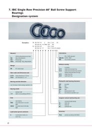
12. Designation <strong>IBC</strong> cylindrical roller bearings<br />
46-104<br />
N 10 13 . . M1<br />
AC- NU 2 10 . EA P . P52 . A15<br />
NJ 3 08 . EA . MCA . C3<br />
NUP 22 05 . EA . M1A . P6<br />
NCF 29 14 . V<br />
NJG 23 24 . VH<br />
Material<br />
Steel rollers 100Cr6<br />
AC- Rings ATCoated<br />
Design<br />
NU..<br />
NJ..<br />
NUP..<br />
N..<br />
NCF..<br />
NJG..<br />
Designation of the bearing series<br />
10.. 2..<br />
30.. 3..<br />
29.. 22..<br />
23..<br />
Designation of the bore diameter<br />
00 10 mm 02 15 mm<br />
01 12 mm 03 17 mm<br />
From number 04 x 5 [mm]<br />
Basic form<br />
EA.. EXAD<br />
V.. Full complement<br />
VH.. Full complement + self retaining<br />
of rollers<br />
Coating ATCoat<br />
A11 Inner ring and outer ring coated<br />
(IR + OR)<br />
A15 IR + OR coated, rolling elements<br />
and cage corrosion resistant<br />
A 21 Inner ring coated<br />
A 31 Outer ring coated<br />
Precision classes and radial clearance<br />
P6, P63, P52, P53 = P5 + C3<br />
Cage<br />
MC one-piece-machined-brass cage,<br />
located on rolling elements<br />
MCA one-piece-machined-brass cage,<br />
located on outer ring<br />
M1 one-piece-machined-brass cage,<br />
riveted, located on rolling elements<br />
M1A one-piece-machined-brass cage,<br />
riveted, located on outer ring<br />
P Polyamid window type cage, glassfibre<br />
inforced, located on rolling elements<br />
J<br />
K<br />
Steel sheet cage<br />
PEEK glass fibre reinforced window<br />
type cage, located on rolling elements<br />
Designation system 44-106<br />
<strong>IBC</strong> INDUSTRIAL BEARINGS AND COMPONENTS 19
46-101<br />
Basic Basic Basic load ratings Fatigue limit Minimal load Limiting Reference Weight<br />
dimensions designation stat. dyn. load factor speed speed<br />
d D B C 0 C P u (radial) k f n G n R<br />
mm N N min –1 kg<br />
15 35 11 N 202.EA 10 400 15 100 1 470 0.15 22 000 17 600 0.047<br />
15 35 11 NU 202.EA 10 400 13 800 1 220 0.15 24 000 19 800 0.050<br />
17 40 12 N 203.EA 14 600 19 000 1 730 0.15 20 000 17 200 0.070<br />
17 40 12 NU 203.EA 14 600 19 000 1 730 0.15 20 000 17 200 0.070<br />
17 40 16 NU 2203.EA 21 900 26 200 2 650 0.20 20 000 16 200 0.090<br />
17 47 14 NU 303.EA 21 200 27 300 2 550 0.15 17 000 14 400 0.120<br />
20 47 14 N 204.EA 24 700 28 800 2 750 0.15 17 500 14 500 0.130<br />
20 47 14 NU 204.EA 24 700 28 800 2 750 0.15 17 500 14 500 0.130<br />
20 47 18 NU 2204.EA 31 000 34 100 3 450 0.20 17 500 13 700 0.140<br />
20 52 15 NU 304.EA 26 000 36 000 3 250 0.15 16 000 13 500 0.160<br />
20 52 21 NU 2304.EA 38 000 48 000 4 800 0.29 16 000 11 900 0.220<br />
25 47 12 NU 1005 12 900 16 700 1 400 0.10 18 000 18 000 0.080<br />
25 52 15 N 205.EA 27 500 31 600 3 350 0.15 15 500 12 900 0.140<br />
25 52 15 NU 205.EA 27 500 31 600 3 350 0.15 15 500 12 900 0.140<br />
25 52 18 NU 2205.EA 34 500 37 800 4 250 0.20 15 500 11 900 0.170<br />
25 62 17 NU 305.EA 36 500 47 300 4 550 0.15 13 500 11 100 0.250<br />
25 62 24 NU 2305.EA 55 000 65 000 6 950 0.25 13 500 10 200 0.350<br />
30 55 13 NU 1006 19 300 22 900 1 860 0.10 15 000 14 000 0.130<br />
30 62 16 N 206.EA 36 000 44 500 4 550 0.15 13 000 11 400 0.210<br />
30 62 16 NU 206.EA 36 000 44 500 4 550 0.15 13 000 11 400 0.210<br />
30 62 20 NU 2206.EA 48 500 56 000 6 100 0.20 13 000 10 600 0.270<br />
30 72 19 NU 306.EA 48 000 59 800 6 200 0.15 11 000 10 000 0.370<br />
30 72 27 NU 2306.EA 75 000 84 500 9 650 0.25 11 000 9 100 0.530<br />
35 62 14 NU 1007 26 000 29 000 4 550 0.10 13 000 12 000 0.180<br />
35 72 17 N 207.EA 48 500 57 000 6 100 0.15 11 000 9 600 0.310<br />
35 72 17 NU 207.EA 48 500 57 000 6 100 0.15 11 000 9 600 0.310<br />
35 72 23 NU 2207.EA 64 000 70 700 8 150 0.20 11 000 9 100 0.410<br />
35 80 21 NU 307.EA 63 000 75 500 8 150 0.15 10 000 8 800 0.490<br />
35 80 31 NU 2307.EA 98 000 107 000 12 700 0.25 10 000 8 100 0.730<br />
40 68 15 NU 1008 30 500 33 500 3 000 0.10 18 000 11 000 0.230<br />
40 80 18 N 208.EA 53 000 62 500 6 700 0.15 10 000 8 500 0.380<br />
40 80 18 NU 208.EA 53 000 62 500 6 700 0.15 10 000 8 500 0.380<br />
40 80 23 NU 2208.EA 75 000 82 200 9 650 0.20 10 000 7 900 0.500<br />
40 90 23 NU 308.EA 78 000 94 000 10 200 0.15 8 500 7 600 0.660<br />
40 90 33 NU 2308.EA 119 000 130 500 15 300 0.25 8 500 7 000 0.960<br />
20 <strong>IBC</strong> WÄLZLAGER GMBH
46-101<br />
Basic Dimensions Mounting dimensions<br />
designation<br />
F E s d 1 D 1 r 12min r 34min d amin D amax D bmax r amax r bmax<br />
mm<br />
mm<br />
N 202.EA – 30.3 0.5 21.6 – 0.6 0.3 17.4 32.6 31.0 0.6 0.3<br />
NU 202.EA 19.3 – 1 22.0 28.0 0.6 0.3 17.4 30.8 23.0 0.6 0.3<br />
N 203.EA – 35.1 1 25.2 – 0.6 0.3 21.2 37.6 37.0 0.6 0.3<br />
NU 203.EA 22.1 – 1 25.2 32.5 0.6 0.3 19.4 35.8 24.0 0.6 0.3<br />
NU 2203.EA 22.1 – 1.5 25.2 32.5 0.6 0.3 19.4 35.8 24.0 0.6 0.3<br />
NU 303.EA 24.2 – 1.5 27.7 37.1 1.0 0.6 21.2 41.4 26.0 1.0 0.6<br />
N 204.EA – 41.5 1 29.9 – 1.0 0.6 25.6 42.8 43.0 1.0 0.6<br />
NU 204.EA 26.5 – 1 29.9 38.8 1.0 0.6 24.2 41.4 31.0 1.0 0.6<br />
NU 2204.EA 26.5 – 2 29.9 38.8 1.0 0.6 24.2 41.4 31.0 1.0 0.6<br />
NU 304.EA 27.5 – 0.9 31.4 42.4 1.1 0.6 24.2 45.0 29.0 1.0 0.6<br />
NU 2304.EA 27.5 – 1.9 31.8 42.4 1.1 0.6 24.2 45.0 29.0 1.0 0.6<br />
NU 1005 30.5 – 2 32.7 39.3 0.6 0.3 27.0 43.8 32.0 0.6 0.3<br />
N 205.EA – 46.5 1.3 34.9 – 1.0 0.6 30.6 46.4 33.0 1.0 0.6<br />
NU 205.EA 31.5 – 1.3 34.9 43.8 1.0 0.6 29.2 47.8 48.0 1.0 0.6<br />
NU 2205.EA 31.5 – 1.8 34.9 43.8 1.0 0.6 29.2 46.4 33.0 1.0 0.6<br />
NU 305.EA 34 – 1.3 38.3 50.7 1.1 1.1 32.0 55.0 36.0 1.0 1.0<br />
NU 2305.EA 34 – 2.3 38.3 50.7 1.1 1.1 32.0 55.0 36.0 1.0 1.0<br />
NU 1006 36.5 – 2.1 38.9 46.1 1.0 0.6 33.2 50.4 38.0 1.0 0.6<br />
N 206.EA – 55.5 1.3 41.4 – 1.0 0.6 35.6 57.8 57.0 1.0 0.6<br />
NU 206.EA 37.5 – 1.3 41.4 52.5 1.0 0.6 34.2 56.4 39.0 1.0 0.6<br />
NU 2206.EA 37.5 – 1.8 41.4 52.5 1.0 0.6 34.0 57.0 39.0 1.0 0.6<br />
NU 306.EA 40.5 – 1.4 45.1 59.2 1.1 1.1 37.0 65.0 42.0 1.0 1.0<br />
NU 2306.EA 40.5 – 2.4 45.1 59.2 1.1 1.1 37.0 65.0 42.0 1.0 1.0<br />
NU 1007 42 – 1 44.6 52.4 1.0 0.6 38.2 56.0 44.0 1.0 0.6<br />
N 207.EA – 64 1.3 48.3 – 1.1 0.6 42.0 67.8 66.0 1.0 0.6<br />
NU 207.EA 44 – 1.3 48.3 61.0 1.1 0.6 39.2 65.0 46.0 1.0 0.6<br />
NU 2207.EA 44 – 2.8 48.3 61.0 1.1 0.6 39.2 65.0 46.0 1.0 0.6<br />
NU 307.EA 46.2 – 1.2 51.2 66.6 1.5 1.1 42.0 71.0 48.0 1.5 1.0<br />
NU 2307.EA 46.2 – 2.7 51.2 66.6 1.5 1.1 42.0 71.0 48.0 1.5 1.0<br />
NU 1008 47 – 2.4 49.8 58.2 1.0 0.6 43.2 63.4 49.0 1.0 0.6<br />
N 208.EA – 71.5 1.4 54.1 – 1.1 1.1 47.0 73.0 73.0 1.0 1.0<br />
NU 208.EA 49.5 – 1.4 54.1 68.3 1.1 1.1 47.0 73.0 51.0 1.0 1.0<br />
NU 2208.EA 49.5 – 1.9 54.1 68.3 1.1 1.1 47.0 73.0 51.0 1.0 1.0<br />
NU 308.EA 52 – 1.4 57.7 75.9 1.5 1.5 49.0 81.0 54.0 1.5 1.5<br />
NU 2308.EA 52 – 2.9 57.7 75.9 1.5 1.5 49.0 81.0 54.0 1.5 1.5<br />
<strong>IBC</strong> INDUSTRIAL BEARINGS AND COMPONENTS 21
46-101<br />
Basic Basic Basic load ratings Fatigue limit Minimal load Limiting Reference Weight<br />
dimensions designation stat. dyn. load factor speed speed<br />
d D B C 0 C P u (radial) k f n G n R<br />
mm N N min –1 kg<br />
45 75 16 NU 1009 37 500 40 000 6 300 0.10 11 000 9 500 0.290<br />
45 85 19 N 209.EA 63 000 70 700 8 150 0.15 9 000 8 000 0.440<br />
45 85 19 NU 209.EA 63 000 70 700 8 150 0.15 9 000 8 000 0.440<br />
45 85 23 NU 2209.EA 82 000 86 000 10 600 0.20 9 000 7 400 0.540<br />
45 100 25 NU 309.EA 98 000 113 500 12 900 0.15 7 600 7 000 0.890<br />
45 100 36 NU 2309.EA 153 000 161 000 20 000 0.25 7 600 6 400 1.300<br />
50 80 16 NU 1010 41 500 42 500 6 700 0.10 9 500 9 000 0.310<br />
50 90 20 N 210.EA 69 000 74 000 8 800 0.15 8 500 7 600 0.490<br />
50 90 20 NU 210.EA 69 000 74 000 8 800 0.15 8 500 7 600 0.490<br />
50 90 23 NU 2210.EA 88 000 91 000 11 400 0.20 8 500 6 900 0.570<br />
50 110 27 NU 310.EA 113 000 128 500 15 000 0.15 7 100 6 400 1.150<br />
50 110 40 NU 2310.EA 187 000 189 000 24 500 0.25 7 100 5 800 1.800<br />
55 90 18 NU 1011 62 000 53 000 8 300 0.10 8 500 8 000 0.450<br />
55 100 21 N 211.EA 95 000 98 000 12 200 0.15 7 500 6 600 0.660<br />
55 100 21 NU 211.EA 95 000 98 000 12 200 0.15 7 500 6 600 0.660<br />
55 100 25 NU 2211.EA 118 000 115 500 15 300 0.20 7 500 6 100 0.790<br />
55 120 29 NU 311.EA 139 000 157 500 18 600 0.15 6 300 5 800 1.500<br />
55 120 43 NU 2311.EA 230 000 233 500 30 500 0.25 6 300 5 300 2.200<br />
60 95 18 NU 1012 55 000 52 000 5 300 0.10 11 000 8 000 0.480<br />
60 110 22 N 212.EA 102 000 110 000 13 400 0.15 6 900 6 000 0.830<br />
60 110 22 NU 212.EA 102 000 110 000 13 400 0.15 6 900 6 000 0.830<br />
60 110 28 NU 2212.EA 152 000 149 000 20 000 0.20 6 900 5 500 1.100<br />
60 130 31 NU 312.EA 157 000 175 000 20 800 0.15 5 800 5 400 1.850<br />
60 130 46 NU 2312.EA 260 000 263 000 34 500 0.25 5 800 4 900 2.800<br />
65 100 18 NU 1013 58 000 53 000 9 800 0.10 7 500 7 000 0.510<br />
65 120 23 N 213.EA 119 000 124 500 15 600 0.15 6 300 5 600 1.050<br />
65 120 23 NU 213.EA 119 000 124 500 15 600 0.15 6 300 5 600 1.050<br />
65 120 31 NU 2213.EA 181 000 173 000 24 000 0.20 6 100 5 200 1.450<br />
65 140 33 NU 313.EA 191 000 213 000 25 500 0.15 5 400 5 100 2.300<br />
65 140 48 NU 2313.EA 285 000 290 000 38 000 0.25 5 400 4 600 3.350<br />
70 110 20 NU 1014 78 000 75 000 12 000 0.10 7 000 6 300 0.700<br />
70 125 24 N 214.EA 137 000 138 500 18 000 0.15 5 800 5 300 1.150<br />
70 125 24 NU 214.EA 137 000 138 500 18 000 0.15 5 800 5 300 1.150<br />
70 125 31 NU 2214.EA 194 000 182 000 25 500 0.20 5 800 4 900 1.550<br />
70 150 35 NU 314.EA 222 000 239 000 29 000 0.15 5 000 4 600 2.800<br />
70 150 51 NU 2314.EA 325 000 320 000 41 500 0.25 5 000 4 300 4.000<br />
22 <strong>IBC</strong> WÄLZLAGER GMBH
46-101<br />
Basic Dimensions Mounting dimensions<br />
designation<br />
F E s d 1 D 1 r 12min r 34min d amin D amax D bmax r amax r bmax<br />
mm<br />
mm<br />
NU 1009 52.5 – 0.9 55.5 64.5 1.0 0.6 48.2 70.4 54.0 1.0 0.6<br />
N 209.EA – 76.5 1.2 59.1 – 1.1 1.1 52.0 78.0 78.0 1.0 1.0<br />
NU 209.EA 54.5 – 1.2 59.1 73.3 1.1 1.1 52.0 78.0 56.0 1.0 1.0<br />
NU 2209.EA 54.5 – 1.7 59.1 73.3 1.1 1.1 52.0 78.0 56.0 1.0 1.0<br />
NU 309.EA 58.5 – 1.7 64.6 84.1 1.5 1.5 54.0 91.0 61.0 1.5 1.5<br />
NU 2309.EA 58.5 – 3.2 64.6 84.1 1.5 1.5 54.0 91.0 61.0 1.5 1.5<br />
NU 1010 57.5 – 1 60.5 69.5 1.0 0.6 53.2 75.4 60.0 1.0 0,<br />
N 210.EA – 81.5 1.5 64.6 – 1.1 1.1 57.0 83.0 83.0 1.0 1.0<br />
NU 210.EA 59.5 – 1.5 64.6 78.3 1.1 1.1 57.0 83.0 62.0 1.0 1.0<br />
NU 2210.EA 59.5 – 1.5 64.6 78.3 1.1 1.1 57.0 83.0 62.0 1.0 1.0<br />
NU 310.EA 65 – 1.9 71.4 92.5 2.0 2.0 61.0 99.0 67.0 2.0 2.0<br />
NU 2310.EA 65 – 3.4 71.4 92.5 2.0 2.0 61.0 99.0 67.0 2.0 2.0<br />
NU 1011 64.5 – 0.5 67.7 79.2 1.1 1.0 59.6 84.0 67.0 1.0 1.0<br />
N 211.EA – 90 1 71.0 – 1.5 1.1 64.0 93.0 92.0 1.5 1.0<br />
NU 211.EA 66 – 1 71.0 86.6 1.5 1.1 62.0 91.0 68.0 1.5 1.0<br />
NU 2211.EA 66 – 1.5 71.0 86.6 1.5 1.1 62.0 91.0 68.0 1.5 1.0<br />
NU 311.EA 70.5 – 2 77.7 101.4 2.0 2.0 66.0 109.0 73.0 2.0 2.0<br />
NU 2311.EA 70.5 – 3.5 77.7 101.4 2.0 2.0 66.0 109.0 73.0 2.0 2.0<br />
NU 1012 69.5 – 2.9 72.7 82.3 1.1 1.0 64.6 89.0 72.0 1.0 1.0<br />
N 212.EA – 100 1.4 77.7 – 1.5 1.5 69.0 101.0 101.0 1.5 1.5<br />
NU 212.EA 72 – 1.4 77.7 96.1 1.5 1.5 69.0 101.0 74.0 1.5 1.5<br />
NU 2212.EA 72 – 1.4 77.7 96.1 1.5 1.5 69.0 101.0 74.0 1.5 1.5<br />
NU 312.EA 77 – 2.1 84.5 109.6 2.1 2.1 72.0 118.0 79.0 2.0 2.0<br />
NU 2312.EA 77 – 3.6 84.5 109.6 2.1 2.1 72.0 118.0 79.0 2.0 2.0<br />
NU 1013 74.5 – 1 77.7 87.3 1.1 1 69.6 94.0 77.0 1.0 1.0<br />
N 213.EA – 108.5 1.4 84.6 – 1.5 1.5 74.0 111.0 111.0 1.5 1.5<br />
NU 213.EA 78.5 – 1.4 84.6 104.3 1.5 1.5 74.0 111.0 81.0 1.5 1.5<br />
NU 2213.EA 78.5 – 1.9 84.6 104.3 1.5 1.5 74.0 111.0 81.0 1.5 1.5<br />
NU 313.EA 82.5 – 2.2 90.7 118.6 2.1 2.1 77.0 128.0 85.0 2.0 2.0<br />
NU 2313.EA 82.5 – 4.7 90.7 118.6 2.1 2.1 77.0 128.0 85.0 2.0 2.0<br />
NU 1014 80 – 1.3 84.0 96.0 1.1 1.0 74.6 104.0 82.0 1.0 1.0<br />
N 214.EA – 113.5 1.2 89.6 – 1.5 1.5 79.0 116.0 116.0 1.5 1.5<br />
NU 214.EA 83.5 – 1.2 89.6 109.4 1.5 1.5 79.0 116.0 86.0 1.5 1.5<br />
NU 2214.EA 83.5 – 1.7 89.6 109.4 1.5 1.5 79.0 116.0 86.0 1.5 1.5<br />
NU 314.EA 89 – 1.8 97.5 126.8 2.1 2.1 82.0 138.0 91.0 2.0 2.0<br />
NU 2314.EA 89 – 4.8 97.5 126.8 2.1 2.1 82.0 138.0 91.0 2.0 2.0<br />
<strong>IBC</strong> INDUSTRIAL BEARINGS AND COMPONENTS 23
46-101<br />
Basic Basic Basic load ratings Fatigue limit Minimal load Limiting Reference Weight<br />
dimensions designation stat. dyn. load factor speed speed<br />
d D B C 0 C P u (radial) k f n G n R<br />
mm N N min –1 kg<br />
75 115 20 NU 1015 82 000 76 000 8 500 0.10 10 000 6 700 0.740<br />
75 130 25 N 215.EA 156 000 152 000 20 400 0.15 5 600 5 000 1.300<br />
75 130 25 NU 215.EA 156 000 152 000 20 400 0.15 5 600 5 000 1.300<br />
75 130 31 NU 2215.EA 207 000 188 500 27 000 0.20 5 600 4 600 1.600<br />
75 160 37 NU 315.EA 265 000 282 500 33 500 0.15 4 600 4 300 3.400<br />
75 160 55 NU 2315.EA 395 000 385 000 50 000 0.25 4 600 4 000 5.000<br />
80 125 22 NU 1016 99 000 91 000 10 400 0.10 6 300 6 300 0.990<br />
80 140 26 N 216.EA 167 000 162 000 21 200 0.15 5 200 4 700 1.550<br />
80 140 26 NU 216.EA 167 000 162 000 21 200 0.15 5 200 4 700 1.550<br />
80 140 33 NU 2216.EA 243 000 216 000 31 000 0.20 5 200 4 300 2.100<br />
80 170 39 NU 316.EA 275 000 300 000 36 000 0.15 4 400 4 200 4.000<br />
80 170 58 NU 2316.EA 425 000 417 000 55 000 0.25 4 400 3 900 6.000<br />
85 130 22 NU 1017 103 000 93 000 10 800 0.10 9 000 6 000 1.100<br />
85 150 28 N 217.EA 194 000 192 000 24 500 0.15 4 900 4 450 1.900<br />
85 150 28 NU 217.EA 194 000 192 000 24 500 0.15 4 900 4 450 1.900<br />
85 150 36 NU 2217.EA 275 000 253 000 34 500 0.20 4 900 4 000 2.500<br />
85 180 41 NU 317.EA 300 000 320 000 34 500 0.15 4 200 4 000 5.000<br />
85 180 60 NU 2317.EA 445 000 435 000 60 000 0.25 4 200 3 600 7.000<br />
90 140 24 NU 1018 124 000 110 000 12 700 0.10 8 500 5 600 1.350<br />
90 160 30 N 218.EA 217 000 212 000 27 000 0.15 4 600 4 200 2.400<br />
90 160 30 NU 218.EA 217 000 212 000 27 000 0.15 4 600 4 200 2.400<br />
90 160 40 NU 2218.EA 315 000 282 000 39 000 0.20 4 600 3 900 3.200<br />
90 190 43 NU 318.EA 350 000 367 000 43 000 0.15 4 900 3 750 5.900<br />
90 190 64 NU 2318.EA 530 000 505 000 65 500 0.25 3 900 3 400 8.000<br />
95 145 24 NU 1019 130 000 113 000 13 200 0.10 8 000 5 300 1.400<br />
95 170 32 N 219.EA 265 000 257 000 32 500 0.15 4 300 4 000 2.900<br />
95 170 32 NU 219.EA 265 000 257 000 32 500 0.15 4 300 4 000 2.900<br />
95 170 43 NU 2219.EA 370 000 330 000 45 000 0.20 4 300 3700 3.900<br />
95 200 45 NU 319.EA 380 000 390 000 46 500 0.15 3 800 3 600 6.500<br />
95 200 67 NU 2319.EA 580 000 535 000 69 500 0.25 3 800 3 200 9.500<br />
100 150 24 NU 1020 135 000 116 000 13 700 0.10 7 500 5 000 1.500<br />
100 180 34 N 220.EA 305 000 288 000 36 500 0.15 4 100 3 750 3.500<br />
100 180 34 NU 220.EA 305 000 288 000 36 500 0.15 4 100 3 750 3.500<br />
100 180 46 NU 2220.EA 445 000 388 000 54 000 0.20 4 100 3 450 4.800<br />
100 215 47 NU 320.EA 425 000 450 000 51 000 0.15 3 500 3 200 8.000<br />
100 215 73 NU 2320.EA 720 000 675 000 85 000 0.25 3 500 2 800 12.000<br />
24 <strong>IBC</strong> WÄLZLAGER GMBH
46-101<br />
Basic Dimensions Mounting dimensions<br />
designation<br />
F E s d 1 D 1 r 12min r 34min d amin D amax D bmax r amax r bmax<br />
mm<br />
mm<br />
NU 1015 85 – 3 89.0 101.7 1.1 1.0 79.6 109.0 87.0 1.0 1.0<br />
N 215.EA – 118.5 1.2 94.5 – 1.5 1.5 84.0 121.0 121.0 1.5 1.5<br />
NU 215.EA 88.5 – 1.2 94.5 114.4 1.5 1.5 84.0 121.0 91.0 1.5 1.5<br />
NU 2215.EA 88.5 – 1.7 94.5 114.4 1.5 1.5 84.0 121.0 91.0 1.5 1.5<br />
NU 315.EA 95 – 1.8 104.3 136.2 2.1 2.1 87.0 148.0 97.0 2.0 2.0<br />
NU 2315.EA 95 – 4.8 104.3 136.2 2.1 2.1 87.0 148.0 97.0 2.0 2.0<br />
NU 1016 91.5 – 3.3 95.9 109.8 1.1 1.0 86.0 119.0 94.0 1.0 1.0<br />
N 216.EA – 127.3 1.4 101.7 – 2.0 2.0 91.0 129.0 129.0 2.0 2.0<br />
NU 216.EA 95.3 – 1.4 101.7 122.9 2.0 2.0 91.0 129.0 98.0 2.0 2.0<br />
NU 2216.EA 95.3 – 1.4 101.7 122.9 2.0 2.0 91.0 129.0 98.0 2.0 2.0<br />
NU 316.EA 101 – 2.1 110.6 143.9 2.1 2.1 92.0 158.0 104.0 2.0 2.0<br />
NU 2316.EA 101 – 5.1 110.6 143.9 2.1 2.1 92.0 158.0 104.0 2.0 2.0<br />
NU 1017 95.5 – 3.3 100.9 114.8 1.1 1.0 89.6 124.0 99.0 1.0 1.0<br />
N 217.EA – 136.5 1.5 107.6 – 2.0 2.0 96.0 139.0 139.0 2.0 2.0<br />
NU 217.EA 100.5 – 1.5 107.6 131.5 2.0 2.0 96.0 139.0 103.0 2.0 2.0<br />
NU 2217.EA 100.5 – 2 107.6 131.5 2.0 2.0 96.0 139.0 103.0 2.0 2.0<br />
NU 317.EA 108 – 2.3 118.0 152.7 3.0 3.0 99.0 166.0 111.0 2.5 2.5<br />
NU 2317.EA 108 – 5.8 118.0 152.7 3.0 3.0 99.0 166.0 111.0 2.5 2.5<br />
NU 1018 103 – 3.5 107.8 122.9 1.5 1.1 96.0 133.0 106.0 1.5 1.0<br />
N 218.EA – 145 1.8 114.5 – 2.0 2.0 101.0 149.0 148.0 2.0 2.0<br />
NU 218.EA 107 – 1.8 114.5 139.7 2.0 2.0 101.0 149.0 110.0 2.0 2.0<br />
NU 2218.EA 107 – 2.6 114.5 139.7 2.0 2.0 101.0 149.0 110.0 2.0 2.0<br />
NU 318.EA 113.5 – 2.5 124.2 161.6 3.0 3.0 104.0 176.0 116.0 2.5 2.5<br />
NU 2318.EA 113.5 – 6 124.2 161.6 3.0 3.0 104.0 176.0 116.0 2.5 2.5<br />
NU 1019 108 – 3.5 112.8 127.9 1.5 1.1 101.0 138.0 111.0 1.5 1.0<br />
N 219.EA – 154.5 1.7 120.7 – 2.1 2.1 107.0 158.0 157.0 2.0 2.0<br />
NU 219.EA 112.5 – 1.7 120.7 148.6 2.1 2.1 107.0 158.0 115.0 2.0 2.0<br />
NU 2219.EA 112.5 – 3 120.7 148.6 2.1 2.1 107.0 158.0 115.0 2.0 2.0<br />
NU 319.EA 121.5 – 2.9 132.2 169.6 3.0 3.0 109.0 186.0 124.0 2.5 2.5<br />
NU 2319.EA 121.5 – 6.9 132.2 169.6 3.0 3.0 109.0 186.0 124.0 2.5 2.5<br />
NU 1020 113 – 3.5 117.8 132.9 1.5 1.1 106.0 143.0 116.0 1.5 1.0<br />
N 220.EA – 163 1.7 127.5 – 2.1 2.1 112.0 168.0 166.0 2.0 2.0<br />
NU 220.EA 119 – 1.7 127.5 156.9 2.1 2.1 112.0 168.0 122.0 2.0 2.0<br />
NU 2220.EA 119 – 2.5 127.5 156.9 2.1 2.1 112.0 168.0 122.0 2.0 2.0<br />
NU 320.EA 127.5 – 2.9 139.6 182.0 3.0 3.0 114.0 201.0 130.0 2.5 2.5<br />
NU 2320.EA 127.5 – 5.9 139.6 182.0 3.0 3.0 114.0 201.0 130.0 2.5 2.5<br />
<strong>IBC</strong> INDUSTRIAL BEARINGS AND COMPONENTS 25
46-101<br />
Basic Basic Basic load ratings Fatigue limit Minimal load Limiting Reference Weight<br />
dimensions designation stat. dyn. load factor speed speed<br />
d D B C 0 C P u (radial) k f n G n R<br />
mm N N min –1 kg<br />
105 160 26 NU 1021 153 000 131 000 16 000 0.10 7 500 4 800 1.900<br />
105 190 36 N 221.EA 320 000 305 000 36 500 0.15 4 300 3 800 3.950<br />
105 190 36 NU 221.EA 320 000 305 000 36 500 0.15 3 900 3 600 4.000<br />
105 225 49 NU 321.EA 500 000 500 000 57 000 0.15 3 800 3 200 8.800<br />
110 170 28 NU 1022 190 000 166 000 19 300 0.10 7 000 4 500 2.300<br />
110 200 38 N 222.EA 365 000 340 000 42 500 0.15 3 700 3 400 4.900<br />
110 200 38 NU 222.EA 365 000 340 000 42 500 0.15 3 700 3 400 4.900<br />
110 200 53 NU 2222.EA 520 000 448 000 61 000 0.20 3 700 3 200 6.800<br />
110 240 50 NU 322.EA 475 000 495 000 61 000 0.15 3 200 3 050 11.500<br />
110 240 80 NU 2322.EA 800 000 750 000 102 000 0.25 3 100 2 600 17.000<br />
120 180 28 NU 1024 207 000 174 000 20 800 0.10 6 300 4 000 2.500<br />
120 215 40 N 224.EA 415 000 390 000 49 000 0.15 3 400 3 200 5.800<br />
120 215 40 NU 224.EA 415 000 390 000 49 000 0.15 3 400 3 200 5.800<br />
120 215 58 NU 2224.EA 610 000 525 000 72 000 0.20 3 400 2 900 8.400<br />
120 260 55 NU 324.EA 600 000 610 000 69 500 0.15 3 000 2 750 15.000<br />
120 260 86 NU 2324.EA 1 010 000 922 000 116 000 0.25 4 300 2 800 24.000<br />
130 200 33 NU 1026 250 000 212 000 25 000 0.10 5 600 3 800 3.800<br />
130 230 40 N 226.EA 445 000 420 000 51 000 0.15 3 200 3 000 6.500<br />
130 230 40 NU 226.EA 445 000 420 000 51 000 0.15 3 200 3 000 6.500<br />
130 230 64 NU 2226.EA 730 000 615 000 83 000 0.20 3 200 2 700 10.500<br />
130 280 58 NU 326.EA 670 000 680 000 81 500 0.15 2 800 2 430 18.500<br />
130 280 93 NU 2326.EA 1 220 000 1 070 000 137 000 0.25 3 000 2 400 30.000<br />
140 210 33 NU 1028 265 000 216 000 27 000 0.10 5 300 3 600 4.000<br />
140 250 42 N 228.EA 510 000 455 000 57 000 0.15 3 200 2 800 9.000<br />
140 250 42 NU 228.EA 510 000 455 000 57 000 0.15 3 200 2 800 9.000<br />
140 250 68 NU 2228.EA 830 000 662 000 93 000 0.20 4 800 2 800 14.700<br />
140 300 62 NU 328.EA 800 000 785 000 88 000 0.15 2 600 2 300 22.500<br />
140 300 102 NU 2328.EA 1 390 000 1 210 000 150 000 0.25 3 600 2 400 38.000<br />
150 225 35 NU 1030 310 000 248 000 30 000 0.10 5 000 3 200 4.900<br />
150 270 45 N 230.EA 590 000 520 000 64 000 0.15 2 800 2 600 11.400<br />
150 270 45 NU 230.EA 590 000 520 000 64 000 0.15 2 800 2 600 11.400<br />
150 270 73 NU 2230.EA 970 000 760 000 100 000 0.20 2 800 2 600 19.000<br />
150 320 65 NU 330.EA 930 000 900 000 100 000 0.15 2 600 2 200 27.500<br />
150 320 108 NU 2330.EA 1 600 000 1 375 000 166 000 0.25 3 400 2 200 45.000<br />
26 <strong>IBC</strong> WÄLZLAGER GMBH
46-101<br />
Basic Dimensions Mounting dimensions<br />
designation<br />
F E s d 1 D 1 r 12min r 34min d amin D amax D bmax r amax r bmax<br />
mm<br />
mm<br />
NU 1021 119.5 – 3.8 124.7 141.0 2.0 1.1 111.0 151.0 122.0 2.0 1.0<br />
N 221.EA – 173 2 134.0 – 2.1 2.1 117.0 178.0 176.0 2.0 2.0<br />
NU 221.EA 125 – 2 134.0 165.1 2.1 2.1 117.0 178.0 128.0 2.0 2.0<br />
NU 321.EA 133 – 3.4 146.5 190.0 3.0 3.0 119.0 211.0 136.0 2.5 2.5<br />
NU 1022 125 – 3.8 131.0 149.7 2.0 1.1 116.0 161.0 128.0 2.0 1.0<br />
N 222.EA – 180.5 2.1 141.8 – 2.1 2.1 122.0 188.0 183.0 2.0 2.0<br />
NU 222.EA 132.5 – 2.1 141.8 173.8 2.1 2.1 122.0 188.0 135.0 2.0 2.0<br />
NU 2222.EA 132.5 – 3.7 141.8 173.8 2.1 2.1 122.0 188.0 135.0 2.0 2.0<br />
NU 322.EA 143 – 3 155.9 200.9 3.0 3.0 124.0 226.0 146.0 2.5 2.5<br />
NU 2322.EA 143 – 7.5 155.9 200.9 3.0 3.0 124.0 226.0 146.0 2.5 2.5<br />
NU 1024 135 – 3.8 141.0 159.7 2.0 1.1 126.0 171.0 138.0 2.0 1.0<br />
N 224.EA – 195.5 1.9 153.5 – 2.1 2.1 132.0 203.0 199.0 2.0 2.0<br />
NU 224.EA 143.5 – 1.9 153.5 187.8 2.1 2.1 132.0 203.0 146.0 2.0 2.0<br />
NU 2224.EA 143.5 – 3.8 153.5 187.8 2.1 2.1 132.0 203.0 146.0 2.0 2.0<br />
NU 324.EA 154 – 3.7 168.7 218.7 3.0 3.0 134.0 246.0 157.0 2.5 2.5<br />
NU 2324.EA 154 – 7.2 168.7 218.7 3.0 3.0 134.0 246.0 157.0 2.5 2.5<br />
NU 1026 148 – 4.7 154.8 175.9 2.0 1.1 136.0 191.0 151.0 2.0 1.0<br />
N 226.EA – 209.5 2.1 164.2 – 3.0 3.0 144.0 216.0 213.0 2.5 2.5<br />
NU 226.EA 153.5 – 2.1 164.2 201.2 3.0 3.0 144.0 216.0 156.0 2.5 2.5<br />
NU 2226.EA 153.5 – 4.3 164.2 201.2 3.0 3.0 144.0 216.0 156.0 2.5 2.5<br />
NU 326.EA 167 – 3.7 182.3 235.2 4.0 4.0 147.0 263.0 170.0 3.0 3.0<br />
NU 2326.EA 167 – 8.7 182.3 235.2 4.0 4.0 147.0 263.0 170.0 3.0 3.0<br />
NU 1028 158 – 4.4 164.8 185.9 2.0 1.1 146.0 201.0 161.0 2.0 1.0<br />
N 228.EA – 225 2.5 180.0 – 3.0 3.0 154.0 236.0 172.0 2.5 2.5<br />
NU 228.EA 169 – 2.5 180.0 216.7 3.0 3.0 154.0 236.0 172.0 2.5 2.5<br />
NU 2228.EA 169 – 4.4 180.0 216.7 3.0 3.0 154.0 236.0 172.0 2.5 2.5<br />
NU 328.EA 180 – 3.7 196.0 251.7 4.0 4.0 157.0 283.0 183.0 3.0 3.0<br />
NU 2328.EA 180 – 9.7 196.0 251.7 4.0 4.0 157.0 283.0 183.0 3.0 3.0<br />
NU 1030 169.5 – 4.9 176.7 199.0 2.1 1.5 157.0 215.0 173.0 2.0 1.5<br />
N 230.EA – 242 2.5 193.7 – 3.0 3.0 163.0 256.0 185.0 2.5 2.5<br />
NU 230.EA 182 – 2.5 193.7 233.2 3.0 3.0 163.0 256.0 185.0 2.5 2.5<br />
NU 2230.EA 182 – 4.9 193.7 233.2 3.0 3.0 164.0 256.0 185.0 2.5 2.5<br />
NU 330.EA 193 – 4 210.1 269.8 4.0 4.0 167.0 303.0 196.0 3.0 3.0<br />
NU 2330.EA 193 – 10.5 210.1 269.8 4.0 4.0 167.0 303.0 196.0 3.0 3.0<br />
<strong>IBC</strong> INDUSTRIAL BEARINGS AND COMPONENTS 27
13. Single row full complement cylindrical roller bearings<br />
Beside single row cylindrical roller bearings with cage the<br />
product range is complemented by <strong>IBC</strong> single row full<br />
complement cylindrical roller bearings. These have solid<br />
inner rings and outer rings as well as rib-guided cylindrical<br />
rollers. As they are equipped with the largest possible<br />
number of rolling elements they have a high load-carrying<br />
capacity, they are very stiff and are especially suited for<br />
application in space-saving constructions. Nevertheless, it<br />
has to be considered that on account of the kinematic ratios<br />
they are not able to achieve such a high rotational<br />
speed as single row cylindrical roller bearings with cage.<br />
Dimensions<br />
The main dimensions of single row full complement <strong>IBC</strong><br />
cylindrical roller bearings are correspondent with the specifications<br />
in DIN 616:2000 or ISO 15:1998.<br />
Series<br />
Single row full complement cylindrical roller bearings are<br />
not only available as a slim series 29 but also in broader<br />
versions in the designs 30, 22 and 23.<br />
Other variations are available on request.<br />
Designs<br />
Single row full complement cylindrical roller bearings are<br />
manufactured in the designs NCF and NJG.<br />
The full complement cylindrical roller bearings are neither<br />
sealed nor greased. They can be oil lubricated or grease<br />
lubricated at the front.<br />
<strong>Bearings</strong> of the series NCF have an inner ring with two<br />
solid ribs and an outer ring with one solid rib that is able to<br />
guide the shaft axially in one direction. Besides, a snap<br />
ring on the side of the outer ring without rib holds the bearing<br />
together. They are able to take on axial loads in one direction<br />
and are manufactured in the series 29, 30 and 22.<br />
Single row full complement cylindrical roller bearings of<br />
the design NJG have a self-retaining roller set. Thus the<br />
outer ring with two solid ribs and the roller assembly can<br />
be dismantled from the inner ring with a solid rib. No special<br />
safety device is necessary for preventing the rollers<br />
against falling out which makes the installation and removal<br />
substantially easier. They are also able to take on<br />
axial loads in one direction. <strong>Bearings</strong> of the design NJG<br />
are designed for slowly turning applications with especially<br />
highly loads and are manufactured in the heavy series 23.<br />
With bearing series NCF as well as with NJG the inner<br />
ring can be displaced in one direction axially by the distance<br />
s (see table). The maximum axial movement from<br />
the central position (s) is designed in such a manner that<br />
low axial displacements can be compensated, e.g., as a<br />
result of thermal expansion of the shaft compared with the<br />
housing.<br />
Bearing materials<br />
Bearing rings and rolling elements are manufactured from<br />
bearing steel 100Cr6 (1.3505) according to SAE52100<br />
and SUJ2.<br />
Heat treatment<br />
Single row full complement <strong>IBC</strong> cylindrical roller bearings<br />
are usually dimension-stable up to an operating temperature<br />
of 120 °C. In addition and on request, higher valued<br />
heat treatment is available for higher temperatures. The<br />
bearings for high temperatures are marked with the additional<br />
figures S1, S2, and S3.<br />
Please note that the load-carrying capacities of the bearings<br />
that are constantly exposed to higher operating temperatures<br />
are reduced.<br />
Radial internal clearance<br />
<strong>IBC</strong> manufactures single row full complement cylindrical<br />
roller bearings as a standard with radial internal clearance<br />
normal (CN) or C3. Some cylindrical roller bearings are<br />
available with the smaller clearance C2 or with the larger<br />
clearance C4. <strong>Bearings</strong> with clearance C5 are available on<br />
request.<br />
The values of the radial internal clearance of single row<br />
full complement cylindrical roller bearings comply to<br />
DIN 620-4:1987 or ISO 5753:1991. They are valid for not<br />
built-in bearings with measuring load zero. In addition,<br />
these bearings are also available with „internal radial preload<br />
“ as a special design.<br />
Skewing<br />
The skewing of the inner ring towards the outer ring that is<br />
allowed without reducing the service life of single row full<br />
complement cylindrical roller bearings is dependent on the<br />
load ratio C/P and is limited to a few angular minutes.<br />
For the cylindrical roller bearings of the narrow series 29<br />
the skewing is 4 angular minutes while it is 3 angular minutes<br />
for the broader bearing series (30, 22 and 23). Please<br />
note that the listed approximate values for bearings that<br />
are not axially guided have their validity on condition of<br />
constant position of the axis of shaft and housing.<br />
Note<br />
Please note that skewing causes a certain compulsive<br />
running from which extended running noise may result and<br />
which may also limit service life. Please, contact our technical<br />
consultation teams in such cases in which skewing is<br />
expected to exceed the permitted values.<br />
Tolerances<br />
Beside the standard tolerance PN according to<br />
DIN 620-2:1988 or ISO 492-2002 single row full complement<br />
cylindrical roller bearings are also available in the<br />
higher tolerance classes P6 and P5.<br />
Equivalent dynamic bearing load<br />
The following applies for dynamically stressed full complement<br />
cylindrical roller bearings that are in use as loose fit<br />
bearings:<br />
P = F r [4.0]<br />
If the cylindrical roller bearings are also used as an axial<br />
guidance of the shaft, then the equivalent dynamic bearing<br />
load can be approximated from:<br />
28 <strong>IBC</strong> WÄLZLAGER GMBH
P = F r<br />
bei F a / F r ≤ e<br />
P = 0.92 • F r + Y • F a bei F a / F r > e [4.1]<br />
P equivalent dynamic bearing load [N]<br />
F r radial load [N]<br />
e limit value<br />
0.3 with bearings of the series 29, 30, 22 and 23<br />
Y axial load factor<br />
0.4 with bearings of the series 29, 30, 22 and 23<br />
The ratio of F a / F r shouldn’t exceed the value of 0.5 with<br />
axially loaded single row full complement cylindrical roller<br />
bearings as an optimum run is only given with radial load<br />
at the same time.<br />
Equivalent static bearing load<br />
The following applies for statically stressed single row full<br />
complement cylindrical roller bearings:<br />
P 0 = F r [4.2]<br />
P 0 equivalent static bearing load [N]<br />
Minimum load<br />
To ensure an trouble free operation, in particular with fairly<br />
quick-rotating bearings (n > 0.5 times the reference rotational<br />
speed) in which the weight forces of the rolling elements<br />
as well as the friction within the lubricant can influence<br />
the rolling characteristics in the cylindrical roller<br />
bearings negatively and in which damaging sliding between<br />
the rolling elements and the tracks can appear<br />
there ought to be a minimum load. This also applies to<br />
bearings that are subjected to quick stress cycles.<br />
Use the following formula for approximate calculation of<br />
the minimum radial load for single row full complement<br />
cylindrical roller bearings:<br />
n<br />
( )<br />
F rmin = k r • 0.6 + 0.4 • • d m<br />
2<br />
n r<br />
[4.3]<br />
F rmin minimum radial load [N]<br />
k r radial minimum load factor<br />
n service speed [min -1 ]<br />
n r reference rotational speed [min -1 ]<br />
d m mean diameter of bearing 0.5 • (d + D) [mm]<br />
With the application of high viscosity lubricants as well as<br />
with cold starting it is possible that higher minimum loads<br />
are necessary. In general, the dead weight of the supported<br />
parts and the external forces already cause the radial<br />
load to be higher than the minimum load is. However, if the<br />
ascertained limit value is under-run an additional radial<br />
load of the bearings is necessary.<br />
sipation from the bearing. Usually a viscosity ratio of κ ≥ 2<br />
can be assumed as well as a specific heat dissipation of<br />
0.5 mW/mm² • K referring to the bearing shell surface<br />
(π • D • B) as well as a difference in temperature of 60 °C<br />
between operating temperature of the bearing and temperature<br />
of the installation surroundings, so that the maximum<br />
value of the constant axial load can be determined exactly<br />
enough by using the following formula:<br />
Dynamic axial load-carrying capacity<br />
Besides taking on radial loads, bearings with ribs on the<br />
inner ring and outer ring are also able to take on axial<br />
loads. The load-carrying capacity of the axial sliding surfaces<br />
at the rib and of the rollers decisively determine the<br />
axial load capacity, so that it predominantly depends on<br />
the factors lubrication, operating temperature and heat disk<br />
1 • C o • 10 4<br />
F a max = – k 2 • F r [4.4]<br />
n • (d + D)<br />
F a max maximum axial load<br />
[kN]<br />
C o static load rating [kN]<br />
F r radial load [kN]<br />
k 1 bearing coefficient<br />
1.00 with oil lubrication<br />
0.50 with grease lubrication<br />
k 2 bearing factor<br />
0.30 with oil lubrication<br />
0.15 with grease lubrication<br />
n service speed [min -1 ]<br />
d diameter of bearing bore [mm]<br />
D outer diameter of bearing [mm]<br />
For the actual viscosity with grease lubrication the viscosity<br />
of the base oil is to be used. If there is a viscosity ratio<br />
of κ < 2 then both friction and wear increase. With low rotational<br />
speed this can be reduced by using e.g. oils with<br />
wear protection and suitable EP additives.<br />
For continuing axial loads the application of greases which<br />
are distinguished with an oil separation of at least 3% according<br />
to DIN 51817 is recommended. Besides, lubrication<br />
intervals ought to be reduced. Please notice that the<br />
shown maximum axial load value is valid under the circumstance<br />
that constant axial load is provided with sufficient<br />
lubrication of the contact surfaces. If short period active<br />
axial loads or shock impact axial loads appear, then<br />
higher limit values are permitted. Nevertheless, it should to<br />
be seen to the fact that the limit values are not exceeded<br />
with regard to the lip crack.<br />
In order to avoid lip crack the limit values concerning rib<br />
stress are necessarily to be complied with. With single row<br />
full complement cylindrical roller bearings the constant axial<br />
load shouldn’t exceed the value F a = 0.0023 • D 1.7 . With<br />
only short stresses which only appear now and then the<br />
value F a = 0.007 • D 1.7 should be kept.<br />
F a permanent or occasional axial load [kN]<br />
D outer diameter of bearing [mm]<br />
The size of the contact surfaces on the counterparts and<br />
the axial runout accuracy is also important for a constant<br />
rib load as well as for a sufficient runout accuracy of the<br />
shaft with axially highly loaded cylindrical roller bearings.<br />
<strong>IBC</strong> INDUSTRIAL BEARINGS AND COMPONENTS 29
Thus, a support of the ribs on the complete height is re -<br />
commendable. Please notice that with very strong bending<br />
of the shaft bending fatigue stress can appear, caused by<br />
the support of the ribs.<br />
Thus, e.g., the diameter of the shaft shoulder arises for the<br />
rib on the inner ring as follows:<br />
d as = 0.5 • (d 1 + F) [4.5]<br />
d as recommended diameter of shaft shoulder [mm]<br />
d 1 diameter of inner ring rib [mm]<br />
F diameter of inner ring track [mm]<br />
If skewing between inner ring and outer ring occurs for<br />
more than one angular minute, then this causes an essential<br />
change of the force introduction ratios of the ribs. This<br />
may cause loss of the included safety factor, resulting in<br />
lower axial loads than permitted. In these cases please<br />
contact our technical consultation teams.<br />
30 <strong>IBC</strong> WÄLZLAGER GMBH
Notes<br />
<strong>IBC</strong> INDUSTRIAL BEARINGS AND COMPONENTS 31
46-102<br />
Basic Basis Basic load ratings Fatigue limit Limiting Reference Weight<br />
dimensions designation stat. dyn. load speed speed<br />
d D B C 0 C P u (radial) n G n R<br />
mm N N min –1 kg<br />
20 42 16 NCF 3004 28 500 28 100 3 100 10 000 8 500 0.110<br />
20 47 18 NCF 2204 37 500 45 500 6 100 9 700 6 500 0.160<br />
25 47 16 NCF 3005 35 500 31 900 3 800 9 000 7 000 0.120<br />
25 52 18 NCF 2205 45 000 51 000 7 400 8 400 5 500 0.180<br />
25 62 24 NJG 2305 68 000 68 200 8 500 5 600 4 500 0.380<br />
30 55 19 NCF 3006 44 000 39 600 5 000 7 500 6 000 0.20<br />
30 62 20 NCF 2206 65 000 70 000 10 200 7 000 4 550 0.300<br />
30 72 27 NJG 2306 86 500 84 200 11 000 4 800 4 000 0.560<br />
35 62 20 NCF 3007 56 000 48 400 6 550 6 700 5 300 0.260<br />
35 72 23 NCF 2207 79 000 88 000 12 700 6 100 4 200 0.440<br />
35 80 31 NJG 2307 114 000 108 000 14 300 4 300 3 400 0.750<br />
40 68 21 NCF 3008 69 500 57 200 8 150 6 000 4 800 0.310<br />
40 80 23 NCF 2208 93 000 97 000 14 900 5 400 3 600 0.550<br />
40 90 33 NJG 2308 156 000 145 000 20 000 3 600 3 000 1.000<br />
45 75 23 NCF 3009 78 000 60 500 9 150 5 300 4 300 0.400<br />
45 85 23 NCF 2209 99 000 101 000 16 000 5 000 3 300 0.590<br />
45 100 36 NJG 2309 196 000 172 000 25 500 3 400 2 800 1.450<br />
50 80 23 NCF 3010 98 000 76 500 11 800 5 000 4 000 0.430<br />
50 90 23 NCF 2210 113 000 109 000 18 100 4 650 3 000 0.640<br />
50 110 40 NJG 2310 219 000 232 000 38 500 4 050 2 750 1.810<br />
55 90 26 NCF 3011 140 000 105 000 17 300 4 300 3 400 0.640<br />
55 100 25 NCF 2211 150 000 140 000 25 000 4 200 2 650 0.870<br />
55 120 43 NJG 2311 260 000 233 000 33 500 2 800 2 200 2.300<br />
60 85 16 NCF 2912 80 000 55 000 9 150 4 500 3 600 0.290<br />
60 95 26 NCF 3012 146 000 106 000 18 300 4 000 3 400 0.690<br />
60 110 28 NCF 2212 180 000 169 000 31 000 3 800 2 550 1.180<br />
60 130 46 NJG 2312 280 000 285 000 50 000 3 400 2 450 2.880<br />
65 90 16 NCF 2913 88 000 58 300 10 200 4 000 3 200 0.310<br />
65 100 26 NCF 3013 163 000 112 000 20 000 3 800 3 000 0.730<br />
65 120 31 NCF 2213 214 000 198 000 37 000 3 500 2 410 1.570<br />
65 140 48 NJG 2313 360 000 303 000 46 500 2 400 1 900 3.550<br />
32 <strong>IBC</strong> WÄLZLAGER GMBH
46-002<br />
Basic Dimensions Mounting dimensions<br />
designation<br />
F E s d 1 D 1 r 12min r 34min d amin D amax D bmax r amax r bmax<br />
mm<br />
mm<br />
NCF 3004 – 36.8 1.5 29.0 33.0 0.6 0.6 24.0 38.0 40.0 0.6 0.6<br />
NCF 2204 – 41.47 1 30.3 36.9 0.6 0.6 – – – – –<br />
NCF 3005 – 42.5 1.5 34.0 39.0 0.6 0.6 29.0 43.0 45.0 0.6 0.6<br />
NCF 2205 – 46.5 1 35.3 41.9 1.0 1.0 – – – – –<br />
NJG 2305 31.74 – 1.7 40.0 45.0 1.1 – 35.0 50.0 – 1.0 –<br />
NCF 3006 – 49.6 2 40.0 45.0 1.0 1.0 35.0 50.0 52.0 1.0 1.0<br />
NCF 2206 – 55.19 1 42.0 50.6 1.0 1.0 – – – – –<br />
NJG 2306 38.36 – 1.8 43.2 56.4 1.1 – 37.0 65.0 – 1.0 –<br />
NCF 3007 – 55.5 2 45.0 51.0 1.0 1.0 40.0 57.0 59.0 1.0 1.0<br />
NCF 2207 – 63.9 1 47.0 59.3 1.1 1.1 – – – – –<br />
NJG 2307 44.75 – 2 50.4 65.8 1.5 – 44.0 71.0 – 1.5 –<br />
NCF 3008 – 61.7 2 50.0 58.0 1.0 1.0 45.0 63.0 65.0 1.0 1.0<br />
NCF 2208 – 70.94 1 54.0 66.3 1.1 1.1 – – – – –<br />
NJG 2308 51.15 – 2.4 57.6 75.2 1.5 – 49.0 81.0 – 1.5 –<br />
NCF 3009 – 66.9 2 55.0 62.0 1.0 1.0 50.0 70.0 72.0 1.0 1.0<br />
NCF 2209 – 74.43 1 57.5 69.8 1.1 1.1 – – – – –<br />
NJG 2309 56.14 – 2.4 62.5 80.1 1.5 – 54.0 91.0 – 1.5 –<br />
NCF 3010 – 72.3 2 59.0 68.0 1.0 1.0 55.0 75.0 77.0 1.0 1.0<br />
NCF 2210 – 81.4 1 64.4 76.7 1.1 1.1 – – – – –<br />
NJG 2310 60.72 – 3 68.3 89.7 2.0 2.0 59.0 102.0 – 2.0 –<br />
NCF 3011 – 83.5 2 68.0 79.0 1.1 1.1 61.0 84.0 86.0 1.0 1.0<br />
NCF 2211 – 88.81 1 70.0 84.1 1.5 1.5 – – – – –<br />
NJG 2311 67.14 – 2.6 75.5 98.6 2.0 – 66.0 109.0 – 2.0 –<br />
NCF 2912 – 78.5 1 69.0 75.0 1.0 1.0 65.0 80.0 80.0 1.0 1.0<br />
NCF 3012 – 86.7 2 71.0 82.0 1.1 1.1 66.0 89.0 91.0 1.0 1.0<br />
NCF 2212 – 99.17 1.5 76.8 93.9 1.5 1.5 – – – – –<br />
NJG 2312 73.62 – 3 82.0 105.8 2.1 – 71.0 117.0 – 2.0 –<br />
NCF 2913 – 85 1 75 81 1 1 70 85 85 1 1<br />
NCF 3013 – 93.1 2 78 88 1.1 1.1 71 94 96 1 1<br />
NCF 2213 – 106.25 1.5 82.3 100.7 1.5 1.5 – – – – –<br />
NJG 2313 80.71 – 3 89.9 116.0 2.1 – 77.0 128.0 – 2.0 –<br />
<strong>IBC</strong> INDUSTRIAL BEARINGS AND COMPONENTS 33
46-102<br />
Basic Basis Basic load ratings Fatigue limit Limiting Reference Weight<br />
dimensions designation stat. dyn. load speed speed<br />
d D B C 0 C P u (radial) n G n R<br />
mm N N min –1 kg<br />
70 100 19 NCF 2914 116 000 76 500 13 700 3 800 3 000 0.490<br />
70 110 30 NCF 3014 173 000 128 000 22 400 3 600 2 800 1.020<br />
70 125 31 NCF 2214 184 000 227 000 32 000 3 300 2 270 1.660<br />
70 150 51 NJG 2314 400 000 336 000 50 000 2 200 1 800 4.400<br />
75 105 19 NCF 2915 125 000 79 200 14 600 3 600 2 800 0.520<br />
75 115 30 NCF 3015 190 000 134 000 24 500 3 200 2 600 1.060<br />
75 130 31 NCF 2215 241 000 190 000 33 500 3 150 2 140 1.750<br />
75 160 55 NJG 2315 480 000 396 000 60 000 2 000 1 600 5.350<br />
80 110 19 NCF 2916 132 000 80 900 15 600 3 400 2 600 0.550<br />
80 125 34 NCF 3016 228 000 165 000 29 000 3 000 2 400 1.430<br />
80 140 33 NCF 2216 285 000 226 000 38 500 2 950 2 000 2.150<br />
80 170 58 NJG 2316 570 000 457 000 71 000 1 900 1 500 6.400<br />
85 120 22 NCF 2917 166 000 102 000 20 000 3 200 2 600 0.810<br />
85 130 34 NCF 3017 236 000 172 000 30 000 3 000 2 400 1.510<br />
85 150 36 NCF 2217 325 000 255 000 44 500 2 750 1 930 2.740<br />
85 180 60 NJG 2317 620 000 484 000 76 500 1 800 1 400 7.400<br />
90 120 22 NCF 2918 176 000 106 000 20 800 3 000 2 400 0.840<br />
90 140 37 NCF 3018 280 000 198 000 35 500 2 800 2 200 1.970<br />
90 160 40 NCF 2218 370 000 290 000 51 000 2 600 1 900 3.480<br />
90 190 64 NJG 2318 670 000 528 000 81 500 1 800 1 400 8.750<br />
95 170 43 NCF 2219 435 000 340 000 58 000 2 450 1 800 4.170<br />
95 200 67 NJG 2319 720 000 650 000 120 000 2 200 1 560 10.200<br />
100 140 24 NCF 2920 200 000 128 000 24 500 2 600 2 200 1.140<br />
100 150 37 NCF 3020 310 000 209 000 37 500 2 600 2 000 2.150<br />
100 180 46 NCF 2220 520 000 395 000 70 000 2 310 1 700 5.130<br />
100 215 73 NJG 2320 865 000 682 000 104 000 1 500 1 200 13.000<br />
110 150 24 NCF 2922 220 000 134 000 26 000 2 400 1 900 1.230<br />
110 170 45 NCF 3022 400 000 275 000 47 500 2 200 1 800 3.500<br />
110 200 53 NCF 2222 590 000 455 000 78 000 2 090 1 660 7.240<br />
110 240 80 NJG 2322 1 060 000 858 000 122 000 1 300 1 100 17.500<br />
34 <strong>IBC</strong> WÄLZLAGER GMBH
46-002<br />
Basic Dimensions Mounting dimensions<br />
designation<br />
F E s d 1 D 1 r 12min r 34min d amin D amax D bmax r amax r bmax<br />
mm<br />
mm<br />
NCF 2914 – 92.3 1 81.0 88.0 1.0 1.0 75.0 95.0 95.0 1.0 1.0<br />
NCF 3014 – 100.3 3 81.0 95.0 1.0 1.0 76.0 104.0 106.0 1.0 1.0<br />
NCF 2214 – 111.45 1.5 87.0 105.2 1.5 1.5 – – – – –<br />
NJG 2314 84.22 – 3 93.8 121.0 2.1 – 82.0 138.0 – 2.0 –<br />
NCF 2915 – 97.5 1 86.0 93.0 1.0 1.0 80.0 100.0 100.0 1.0 1.0<br />
NCF 3015 – 107.9 3 89.0 103.0 1.1 1.1 81.0 109.0 111.0 1.0 1.0<br />
NCF 2215 – 116.2 1.5 91.8 110.0 1.5 1.5 – – – – –<br />
NJG 2315 91.24 – 3 101.0 131.0 2.1 – 87.0 148.0 – 2.0 –<br />
NCF 2916 – 102.5 1 91.0 98.0 1.0 1.0 85.0 105.0 105.0 1.0 1.0<br />
NCF 3016 – 117 4 95.0 111.0 1.1 1.1 86.0 119.0 121.0 1.0 1.0<br />
NCF 2216 – 126.3 1.5 98.6 119.3 2.0 2.0 – – – – –<br />
NJG 2316 98.26 – 4 109.0 141.0 4.0 – 92.0 158.0 – 2.0 –<br />
NCF 2917 – 109.5 1 96.0 105.0 1.1 1.1 91.0 114.0 114.0 1.0 1.0<br />
NCF 3017 – 121.4 4 99.0 116.0 1.1 1.1 91.0 124.0 126.0 1.0 1.0<br />
NCF 2217 – 133.75 1.5 104.4 126.3 2.0 2.0 – – – – –<br />
NJG 2317 107 – 4 118.0 149.0 3.0 – 99.0 166.0 – 2.5 –<br />
NCF 2918 – 115.3 1 102.0 111.0 1.1 1.1 96.0 119.0 119.0 1.0 1.0<br />
NCF 3018 – 130.1 4 106.0 124.0 1.5 1.5 97.0 133.0 135.0 1.5 1.5<br />
NCF 2218 – 141.15 2.5 110.2 133.3 2.0 2.0 – – – – –<br />
NJG 2318 105.3 – 4 117.0 152.0 3.0 – 104.0 176.0 – 2.5 –<br />
NCF 2219 – 155.95 2.5 122.0 147.3 2.1 2.1 – – – – –<br />
NJG 2319 114.65 – 4 126.6 161.9 3.0 3.0 110.0 187.5 – 2.5 –<br />
NCF 2920 – 130.5 1.5 114.0 126.0 1.1 1.1 106.0 134.0 134.0 1.0 1.0<br />
NCF 3020 – 139.7 4 115.0 134.0 1.5 1.5 107.0 143.0 145.0 1.5 1.5<br />
NCF 2220 – 163.35 2.5 127.5 154.3 2.1 2.1 – – – – –<br />
NJG 2320 119.3 – 4 133.0 173.0 3.0 – 114.0 201.0 – 2.5 –<br />
NCF 2922 – 141 1.5 124.0 136.0 1.1 1.1 116.0 144.0 144.0 1.0 1.0<br />
NCF 3022 – 156.1 5.5 127.0 149.0 2.0 2.0 120.0 160.0 165.0 2.0 2.0<br />
NCF 2222 – 177.6 4 137.0 168.0 2.1 2.1 – – – – –<br />
NJG 2322 134.3 – 5 151.0 198.0 3.0 – 124.0 226.0 – 2.5 –<br />
<strong>IBC</strong> INDUSTRIAL BEARINGS AND COMPONENTS 35
46-102<br />
Basic Basis Basic load ratings Fatigue limit Limiting Reference Weight<br />
dimensions designation stat. dyn. load speed speed<br />
d D B C 0 C P u (radial) n G n R<br />
mm N N min –1 kg<br />
120 165 27 NCF 2924 290 000 172 000 34 500 2 200 1 800 1.730<br />
120 180 46 NCF 3024 440 000 292 000 52 000 2 000 1 700 3.800<br />
120 215 58 NCF 2224 735 000 512 000 85 000 1 700 1 400 9.050<br />
120 260 86 NJG 2324 1 250 000 952 000 140 000 1 200 1 000 22.500<br />
130 180 30 NCF 2926 360 000 205 000 40 500 2 000 1 600 2.330<br />
130 200 52 NCF 3026 620 000 413 000 72 000 1 900 1 500 5.800<br />
130 230 64 NCF 2226 630 000 860 000 110 000 1 960 1 590 11.250<br />
130 280 93 NJG 2326 1 430 000 1 080 000 156 000 1 200 950 28.000<br />
140 190 30 NCF 2928 390 000 220 000 43 000 1 900 1 500 2.420<br />
140 210 53 NCF 3028 680 000 440 000 78 000 1 800 1 400 6.100<br />
140 250 68 NCF 2228 1 020 000 693 000 114 000 1 500 1 200 14.500<br />
140 300 102 NJG 2328 1 600 000 1 210 000 173 000 1 100 850 35.500<br />
150 210 36 NCF 2930 490 000 292 000 55 000 1 700 1 400 3.770<br />
150 225 56 NCF 3030 710 000 457 000 80 000 1 600 1 300 7.500<br />
150 270 73 NCF 2230 1 180 000 792 000 132 000 1 400 1 100 18.400<br />
150 320 108 NJG 2330 1 930 000 1 450 000 196 000 1 000 800 42.500<br />
36 <strong>IBC</strong> WÄLZLAGER GMBH
46-002<br />
Basic Dimensions Mounting dimensions<br />
designation<br />
F E s d 1 D 1 r 12min r 34min d amin D amax D bmax r amax r bmax<br />
mm<br />
mm<br />
NCF 2924 – 153.8 1.5 135.0 149.0 1.1 1.1 126.0 159.0 159.0 1.0 1.0<br />
NCF 3024 – 167.6 5.5 139.0 160.0 2.0 2.0 130.0 170.0 175.0 2.0 2.0<br />
NCF 2224 – 192.32 4 150.0 184.0 2.1 2.1 131.0 204.0 204.0 2.0 2.0<br />
NJG 2324 147.4 – 5 164.0 213.0 3.0 – 134.0 246.0 – 2.5 –<br />
NCF 2926 – 166.5 2 146.0 151.0 1.5 1.5 137.0 173.0 173.0 1.5 1.5<br />
NCF 3026 – 183 5.5 149.0 175.0 2.0 1.0 140.0 190.0 195.0 2.0 1.0<br />
NCF 2226 – 207.25 5 162.3 197.0 2.1 2.1 141.0 218.0 220.0 2.5 2.5<br />
NJG 2326 157.9 – 6 175.0 226.0 4.0 – 147.0 263.0 – 3.0 –<br />
NCF 2928 – 179.3 2 157.0 174.0 1.5 1.5 147.0 183.0 1830.0 1.5 1.5<br />
NCF 3028 – 197 5.5 163.0 189.0 2.0 1.0 150.0 200.0 205.0 2.0 1.0<br />
NCF 2228 – 221.9 5 173.0 212.0 3.0 3.0 143.0 127.0 127.0 2.5 2.5<br />
NJG 2328 168.5 – 6.5 187.0 245.0 4.0 – 157.0 283.0 – 3.0 –<br />
NCF 2930 – 196 2.5 169.0 189.0 2.0 2.0 160.0 200.0 200.0 2.0 2.0<br />
NCF 3030 – 206 7 170.0 198.0 2.1 1.1 161.0 214.0 234.0 2.0 1.0<br />
NCF 2230 – 236.7 6 184.0 227.0 3.0 3.0 153.0 137.0 137.0 2.5 2.5<br />
NJG 2330 182.5 – 6.5 202.0 261.0 4.0 – 167.0 303.0 – 3.0 –<br />
<strong>IBC</strong> INDUSTRIAL BEARINGS AND COMPONENTS 37
Notes<br />
38 <strong>IBC</strong> WÄLZLAGER GMBH
More of <strong>IBC</strong> . . .<br />
<strong>IBC</strong>. Präzision mit Zukunft.<br />
Lieferprogramm<br />
Hochgenauigkeits-Wälzlager<br />
Präzisionslagereinheiten · Präzisionsspannmuttern<br />
Zylinderrollenlager<br />
TI-I-4010.0 / D<br />
TI-I-5000.0 / D<br />
Company Profile<br />
Product Range<br />
Super Precision <strong>Bearings</strong><br />
T1-I-5000.0 / D (German)<br />
T1-I-5000.0 / E (English)<br />
T1-I-5000.0 / I (Italian)<br />
Product Range<br />
Price List<br />
<strong>Cylindrical</strong> <strong>Roller</strong><br />
<strong>Bearings</strong><br />
T1-1-4010.0 / D (German)<br />
T1-1-4010.0 / E (English)<br />
Schrägkugellager 40°<br />
Präzisions-Spannmuttern<br />
TI-I-4044.0 / D<br />
Labyrinth-Spannmuttern<br />
Labyrinth-Dichtungen<br />
TI-I-5020.0 / D<br />
Wälzlager für Kugelgewindetriebe<br />
Axial-Schrägkugellager 60°<br />
Präzisionslagereinheiten · Präzisionsspannmuttern<br />
TI-I-5010.2 / D<br />
Angular Contact Ball<br />
<strong>Bearings</strong> 40°<br />
T1-1-4044.0 / D (German)<br />
T1-1-4044.0 / E (English)<br />
Precision Locknuts<br />
T1-I-5020.0 / D (German)<br />
T1-I-5020.0 / E (English)<br />
Ball Screw Support<br />
<strong>Bearings</strong><br />
TI-I-5010.2 / D (German)<br />
TI-I-5010.2 / E (English)<br />
Super Precision <strong>Bearings</strong><br />
Service Catalog<br />
T1-1-5003.1 / D (German)<br />
T1-1-5003.2 / E (English)<br />
Linearwälzlagerprogramm<br />
TI-I-7010.0 / D<br />
Linearwälzlager<br />
TI-I-7001.3 / D<br />
<strong>IBC</strong> Wälzlager<br />
mit ATCoat<br />
Beschichtung<br />
TI-1-5010.2/D<br />
Product Range<br />
Linear Motion <strong>Bearings</strong><br />
T1-1-7010.0 / D (German)<br />
T1-1-7010.0 / E (English)<br />
Telescopic-Rails<br />
T1-1-7005.1 / D (German)<br />
Linear Motion <strong>Bearings</strong><br />
TI-1-7001.3 / D (German)<br />
TI-1-7001.3 / E (English)<br />
ATCoated <strong>Bearings</strong><br />
TI-1-5010.2 / D (German)<br />
Note<br />
Copying, even in extracts, is only permitted with our authorisation. The specifications of this issue have been put<br />
together with the biggest care. For possible nonconformities or incompleteness as well as for any appearing damage<br />
arising indirectly or immediately from the use of the information contained here no responsibility can be taken over.<br />
Amendments which serve the progress (advancement) may appear before appearance of a new catalogue.<br />
© Copyright 2007 <strong>IBC</strong>
<strong>IBC</strong> WÄLZLAGER GMBH<br />
INDUSTRIAL BEARINGS AND COMPONENTS<br />
POST OFFICE BOX 1825 · D-35528 WETZLAR (GERMANY)<br />
Tel: +49/64 41/95 53-02<br />
Fax: +49/64 41/5 30 15<br />
Corporate office<br />
Industriegebiet Oberbiel<br />
D-35606 Solms-Oberbiel<br />
e-mail: ibc@ibc-waelzlager.com<br />
http://www.ibc-waelzlager.com<br />
<strong>IBC</strong> INDUSTRIAL BEARINGS<br />
AND COMPONENTS AG<br />
Tel: +41/32/6 52 83 53<br />
Corporate office<br />
Fax: +41/32/6 52 83 58 Kapellstrasse 26<br />
CH-2540 Grenchen<br />
e-mail: ibc@ibcag.ch<br />
http://www.ibc-waelzlager.com