IBC Cylindrical Roller Bearings - Spekuma Kullager AB
IBC Cylindrical Roller Bearings - Spekuma Kullager AB
IBC Cylindrical Roller Bearings - Spekuma Kullager AB
Create successful ePaper yourself
Turn your PDF publications into a flip-book with our unique Google optimized e-Paper software.
5. Interference fits and rotational conditions<br />
Skewing<br />
The skewing of the inner ring in comparison to the outer<br />
ring that is acceptable without leading to service life reduction<br />
is dependent on the load ratio C/P and is limited to a<br />
few angular minutes. With a ratio of C/P ≥ 5 (P/C ≤ 0.2) the<br />
adjustment angle for the bearings of the series 10, 2, 3<br />
may only be max. 4 angular minutes. For cylindrical roller<br />
bearings of the series 22 as well as 23 the skewing may<br />
be only maximum 3 angular minutes. Please note that the<br />
listed approximate values for bearings that are not axially<br />
guided have their validity on condition of constant position<br />
of the axis of shaft and housing. With cylindrical roller<br />
bearings of the series 2 and 3, for example, this approximately<br />
fulfils the radial internal clearance and with series<br />
22 and 23 approximately 2 / 3 of the radial internal clearance<br />
is reached.<br />
Because the ribs are loaded irregularly, given values for<br />
skewing may not be used to a full extent with axially guiding<br />
bearings, as this results in extended wear. In some<br />
cases this may even lead to lip crack. With bearings of the<br />
design NUP or NJ with L-section ring HJ, it is possible that<br />
internal axial tension occurs, because of the fairly small<br />
axial clearance, so that listed maximum skewing values<br />
have no validity.<br />
Note<br />
Please note that skewing causes a certain compulsive run<br />
from which extended running noise may result and which<br />
may also limit service life. Please, contact our technical<br />
consultation teams in such cases in which skewing is expected<br />
to exceed maximum values.<br />
Axial displacement<br />
In general, the guidance of a shaft consists of a locating<br />
bearing and a loose fit bearing. <strong>Cylindrical</strong> roller bearings<br />
of the design NU and N have a loose fit bearing function.<br />
These bearing types are displaceable along the axis and<br />
prevent mutual seizure of the bearings. They permit axial<br />
displacements within the bearing as a result of thermal expansions<br />
between shaft and housing in both directions up<br />
to a certain degree. Because the axial displacement takes<br />
place within the bearing, it takes place within the rotating<br />
bearing virtually without friction. <strong>Cylindrical</strong> roller bearings<br />
of the design NJ allow axial displacements between the<br />
rolling elements and one of the tracks in one direction. In<br />
this case the installation of inner ring and outer ring is possible<br />
with tight fit.<br />
Interference fits and rotational conditions<br />
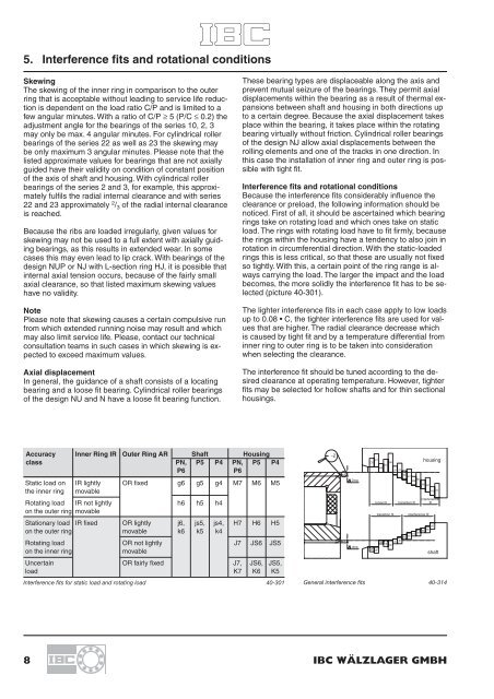
Because the interference fits considerably influence the<br />
clearance or preload, the following information should be<br />
noticed. First of all, it should be ascertained which bearing<br />
rings take on rotating load and which ones take on static<br />
load. The rings with rotating load have to fit firmly, because<br />
the rings within the housing have a tendency to also join in<br />
rotation in circumferential direction. With the static-loaded<br />
rings this is less critical, so that these are usually not fixed<br />
so tightly. With this, a certain point of the ring range is always<br />
carrying the load. The larger the impact and the load<br />
becomes, the more solidly the interference fit has to be selected<br />
(picture 40-301).<br />
The lighter interference fits in each case apply to low loads<br />
up to 0.08 • C, the tighter interference fits are used for values<br />
that are higher. The radial clearance decrease which<br />
is caused by tight fit and by a temperature differential from<br />
inner ring to outer ring is to be taken into consideration<br />
when selecting the clearance.<br />
The interference fit should be tuned according to the desired<br />
clearance at operating temperature. However, tighter<br />
fits may be selected for hollow shafts and for thin sectional<br />
housings.<br />
Accuracy Inner Ring IR Outer Ring AR Shaft Housing<br />
class PN, P5 P4 PN, P5 P4<br />
housing<br />
P6<br />
P6<br />
Static load on IR lightly OR fixed g6 g5 g4 M7 M6 M5<br />
the inner ring movable<br />
interference<br />
Rotating load IR not lightly h6 h5 h4<br />
loose fit transition fit fit<br />
on the outer ring movable<br />
transition fit interference fit<br />
Stationary load IR fixed OR lightly j6, js5, js4, H7 H6 H5<br />
on the outer ring movable k6 k5 k4<br />
Rotating load OR not lightly J7 JS6 JS5<br />
on the inner ring<br />
movable<br />
shaft<br />
Uncertain OR fairly fixed J7, JS6, JS5,<br />
load K7 K6 K5<br />
Interference fits for static load and rotating load 40-301 General interference fits 40-314<br />
8 <strong>IBC</strong> WÄLZLAGER GMBH


