IBC Cylindrical Roller Bearings - Spekuma Kullager AB
IBC Cylindrical Roller Bearings - Spekuma Kullager AB
IBC Cylindrical Roller Bearings - Spekuma Kullager AB
Create successful ePaper yourself
Turn your PDF publications into a flip-book with our unique Google optimized e-Paper software.
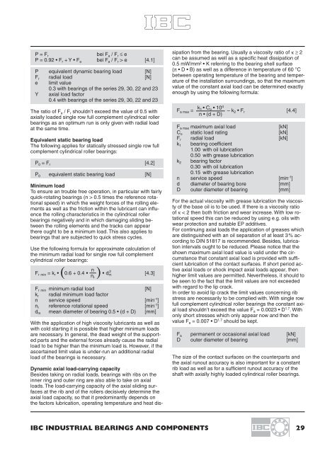
P = F r<br />
bei F a / F r ≤ e<br />
P = 0.92 • F r + Y • F a bei F a / F r > e [4.1]<br />
P equivalent dynamic bearing load [N]<br />
F r radial load [N]<br />
e limit value<br />
0.3 with bearings of the series 29, 30, 22 and 23<br />
Y axial load factor<br />
0.4 with bearings of the series 29, 30, 22 and 23<br />
The ratio of F a / F r shouldn’t exceed the value of 0.5 with<br />
axially loaded single row full complement cylindrical roller<br />
bearings as an optimum run is only given with radial load<br />
at the same time.<br />
Equivalent static bearing load<br />
The following applies for statically stressed single row full<br />
complement cylindrical roller bearings:<br />
P 0 = F r [4.2]<br />
P 0 equivalent static bearing load [N]<br />
Minimum load<br />
To ensure an trouble free operation, in particular with fairly<br />
quick-rotating bearings (n > 0.5 times the reference rotational<br />
speed) in which the weight forces of the rolling elements<br />
as well as the friction within the lubricant can influence<br />
the rolling characteristics in the cylindrical roller<br />
bearings negatively and in which damaging sliding between<br />
the rolling elements and the tracks can appear<br />
there ought to be a minimum load. This also applies to<br />
bearings that are subjected to quick stress cycles.<br />
Use the following formula for approximate calculation of<br />
the minimum radial load for single row full complement<br />
cylindrical roller bearings:<br />
n<br />
( )<br />
F rmin = k r • 0.6 + 0.4 • • d m<br />
2<br />
n r<br />
[4.3]<br />
F rmin minimum radial load [N]<br />
k r radial minimum load factor<br />
n service speed [min -1 ]<br />
n r reference rotational speed [min -1 ]<br />
d m mean diameter of bearing 0.5 • (d + D) [mm]<br />
With the application of high viscosity lubricants as well as<br />
with cold starting it is possible that higher minimum loads<br />
are necessary. In general, the dead weight of the supported<br />
parts and the external forces already cause the radial<br />
load to be higher than the minimum load is. However, if the<br />
ascertained limit value is under-run an additional radial<br />
load of the bearings is necessary.<br />
sipation from the bearing. Usually a viscosity ratio of κ ≥ 2<br />
can be assumed as well as a specific heat dissipation of<br />
0.5 mW/mm² • K referring to the bearing shell surface<br />
(π • D • B) as well as a difference in temperature of 60 °C<br />
between operating temperature of the bearing and temperature<br />
of the installation surroundings, so that the maximum<br />
value of the constant axial load can be determined exactly<br />
enough by using the following formula:<br />
Dynamic axial load-carrying capacity<br />
Besides taking on radial loads, bearings with ribs on the<br />
inner ring and outer ring are also able to take on axial<br />
loads. The load-carrying capacity of the axial sliding surfaces<br />
at the rib and of the rollers decisively determine the<br />
axial load capacity, so that it predominantly depends on<br />
the factors lubrication, operating temperature and heat disk<br />
1 • C o • 10 4<br />
F a max = – k 2 • F r [4.4]<br />
n • (d + D)<br />
F a max maximum axial load<br />
[kN]<br />
C o static load rating [kN]<br />
F r radial load [kN]<br />
k 1 bearing coefficient<br />
1.00 with oil lubrication<br />
0.50 with grease lubrication<br />
k 2 bearing factor<br />
0.30 with oil lubrication<br />
0.15 with grease lubrication<br />
n service speed [min -1 ]<br />
d diameter of bearing bore [mm]<br />
D outer diameter of bearing [mm]<br />
For the actual viscosity with grease lubrication the viscosity<br />
of the base oil is to be used. If there is a viscosity ratio<br />
of κ < 2 then both friction and wear increase. With low rotational<br />
speed this can be reduced by using e.g. oils with<br />
wear protection and suitable EP additives.<br />
For continuing axial loads the application of greases which<br />
are distinguished with an oil separation of at least 3% according<br />
to DIN 51817 is recommended. Besides, lubrication<br />
intervals ought to be reduced. Please notice that the<br />
shown maximum axial load value is valid under the circumstance<br />
that constant axial load is provided with sufficient<br />
lubrication of the contact surfaces. If short period active<br />
axial loads or shock impact axial loads appear, then<br />
higher limit values are permitted. Nevertheless, it should to<br />
be seen to the fact that the limit values are not exceeded<br />
with regard to the lip crack.<br />
In order to avoid lip crack the limit values concerning rib<br />
stress are necessarily to be complied with. With single row<br />
full complement cylindrical roller bearings the constant axial<br />
load shouldn’t exceed the value F a = 0.0023 • D 1.7 . With<br />
only short stresses which only appear now and then the<br />
value F a = 0.007 • D 1.7 should be kept.<br />
F a permanent or occasional axial load [kN]<br />
D outer diameter of bearing [mm]<br />
The size of the contact surfaces on the counterparts and<br />
the axial runout accuracy is also important for a constant<br />
rib load as well as for a sufficient runout accuracy of the<br />
shaft with axially highly loaded cylindrical roller bearings.<br />
<strong>IBC</strong> INDUSTRIAL BEARINGS AND COMPONENTS 29


