IBC Cylindrical Roller Bearings - Spekuma Kullager AB
IBC Cylindrical Roller Bearings - Spekuma Kullager AB
IBC Cylindrical Roller Bearings - Spekuma Kullager AB

Create successful ePaper yourself
Turn your PDF publications into a flip-book with our unique Google optimized e-Paper software.
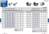
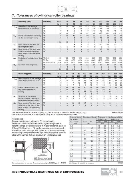
7. Tolerances of cylindrical roller bearings<br />
Inner ring [mm] Accuracy Ø 2.5 10 18 30 50 80 120 150 180 250<br />
to 10 18 30 50 80 120 150 180 250 315<br />
Δ dmp Deviation of the average PN –8 –8 –10 –12 –15 –20 –25 –25 –30 –35<br />
bore diameter on one level P6 –7 –7 –8 –10 –12 –15 –18 –18 –22 –25<br />
P5 –5 –5 –6 –8 –9 –10 –13 –13 –15 –18<br />
P4 –4 –4 –5 –6 –7 –8 –10 –11 –12 –15<br />
K ia Radial runout of the inner ring PN 10 10 13 15 20 25 30 30 40 50<br />
on the assembled bearing P6 6 7 8 10 10 13 18 18 20 25<br />
P5 4 4 4 5 5 6 8 8 10 13<br />
P4 2.5 2.5 3 4 4 5 6 6 8 –<br />
S d Face runout of the front side, P5 7 7 8 8 8 9 10 10 11 13<br />
referring to the bore P4 3 3 4 4 5 5 6 6 7 –<br />
S ia Face runout of the front side, P5 7 7 8 8 8 9 10 10 13 15<br />
referring to the track of the P4 3 3 4 4 5 5 7 7 8 –<br />
inner ring on the assembled<br />
bearing<br />
Δ Bs Deviation of a single inner ring PN, P6 –120 –120 –120 –120 –150 –200 –250 –250 –300 350<br />
width P5, P4 –40 –80 –100 –120 –150 –200 –250 –250 –300 350<br />
PN, P6, P5, P4 –250 –250 –250 –250 –250 –380 –380 –380 –500 –500<br />
V Bs Variation inner ring width P6 15 20 20 20 25 25 30 30 30 35<br />
P5 5 5 5 5 6 7 8 8 10 13<br />
P4 2.5 2.5 2.5 3 4 4 5 5 6 –<br />
Outer ring [mm] Accuracy Ø 18 30 50 80 120 150 180 250 315 400 500<br />
to 30 50 80 120 150 180 250 315 400 500 630<br />
Δ Dmp Max. deviation of the average PN –9 –11 –13 –15 –18 –25 –30 –35 –40 –45 –50<br />
outer diameter on one level P6 –8 –9 –11 –13 –15 –18 –20 –25 –28 –33 –38<br />
P5 –6 –7 –9 –10 –11 –13 –15 –18 –20 –23 –28<br />
P4 –5 –6 –7 –8 –9 –10 –11 –13 –15 –18 –22<br />
K ea Radial runout of the outer PN 15 20 25 35 40 45 50 60 70 80 100<br />
ring on the assembled P6 9 10 13 18 20 23 25 30 35 – –<br />
bearing P5 6 7 8 10 11 13 15 18 20 – –<br />
P4 4 5 5 6 7 8 10 11 13 – –<br />
S D Variation of the surface P5 8 8 8 9 10 10 11 13 13 – –<br />
outline’s incline, referring to P4 4 4 4 5 5 5 7 8 10 – –<br />
the referential side surface<br />
S ea Face runout of the front side P5 8 8 10 11 13 14 15 18 20 – –<br />
referrring to the track of the P4 5 5 5 6 7 8 10 10 13 – –<br />
outer ring on the assembled<br />
bearing<br />
The width tolerances of the outer ring (Δ Cs , V Cs ) are according to those of the inner ring (Δ Bs , V Bs ).<br />
Values in μm<br />
The total width tolerance of a bearing set adds up out of the sum of single tolerances.<br />
Tolerances<br />
Beside the standard tolerance PN according to<br />
DIN 620-2:1988 or ISO 492-2002 single row cylindrical<br />
roller bearings are also available in higher tolerance classes<br />
P6 and P5. <strong>Bearings</strong> in P4 can be manufactured on request.<br />
<strong>Cylindrical</strong> roller bearings with higher accuracy are necessary<br />
for bearing arrangements with high runout accuracy or often<br />
also with bearings that run at very high rotational speed.<br />
Circular arc<br />
(Radius with nominal chamfer radius)<br />
over which no material may protrude<br />
Permissible values for chamfer dimensions according to DIN 620, part 6 40-315<br />
Nominal cham- Diameter of bore Tolerance of the chamfer widths<br />
fer radius d Radial r 1 , r 3 Axial r 2 , r 4<br />
r min , r 12 , r 34 from to min. max. min. max.<br />
mm mm mm mm<br />
0.2 – – 0.2 0.5 0.2 0.8<br />
0.3 – 40 0.3 0.6 0.3 1.0<br />
40 – 0.3 0.8 0.3 1.0<br />
0.6 – 40 0.6 1.0 0.6 2.0<br />
40 – 0.6 1.3 0.6 2.0<br />
1.0 – 50 1.0 1.5 1.0 3.0<br />
50 – 1.0 1.9 1.0 3.0<br />
1.1 – 120 1.1 2.0 1.1 3.5<br />
120 – 1.1 2.5 1.1 4.0<br />
1.5 – 120 1.5 2.3 1.5 4.0<br />
120 – 1.5 3.0 1.5 5.0<br />
2.0 – 80 2.0 3.0 2.0 4.5<br />
80 220 2.0 3.5 2.0 5.0<br />
2.1 – 280 2.1 4.0 2.1 6.5<br />
2.5 – 100 2.5 3.8 2.5 6.0<br />
100 280 2.5 4.5 2.5 6.0<br />
3.0 – 280 3.0 5.0 3.0 8.0<br />
Limit values for chamfer dimensions 40-304<br />
<strong>IBC</strong> INDUSTRIAL BEARINGS AND COMPONENTS 11