IBC Cylindrical Roller Bearings - Spekuma Kullager AB
IBC Cylindrical Roller Bearings - Spekuma Kullager AB
IBC Cylindrical Roller Bearings - Spekuma Kullager AB

Create successful ePaper yourself
Turn your PDF publications into a flip-book with our unique Google optimized e-Paper software.
8. Determination of the bearing size<br />
Equivalent dynamic bearing load<br />
The following applies for dynamically stressed cylindrical<br />
roller bearings that are in use as loose fit bearings:<br />
P = F r [2.0]<br />
If cylindrical roller bearings with ribs on the inner ring and<br />
outer ring are used for axial guiding of the shaft in one or<br />
in both directions, then the equivalent dynamic bearing<br />
load can be approximated from:<br />
P = F r<br />
with F a / F r ≤ e<br />
P = 0.92 • F r + Y • F a with F a / F r > e [2.1]<br />
P equivalent dynamic bearing load [N]<br />
F r radial load [N]<br />
e limit value<br />
0.2 with bearings of the series 10, 2 and 3<br />
0.3 with bearings of the series 22 and 23<br />
Y axial load factor<br />
0.4 with bearings of the series 22 and 23<br />
0.6 with bearings of the series 10, 2 and 3<br />
The ratio of F a /F r shouldn’t exceed the value of 0.5 with<br />
axially loaded single row cylindrical roller bearings as an<br />
optimum run is only given with radial load at the same time.<br />
Equivalent static bearing load<br />
The following applies for statically stressed single row<br />
cylindrical roller bearings:<br />
P 0 = F r [2.2]<br />
P 0 equivalent static bearing load [N]<br />
Minimum load<br />
A minimum load is needed to ensure an undisturbed operation,<br />
in particular with quick-running bearings and bearings<br />
that are used with strong accelerations as well as with<br />
quick changing loads. Should the weight of the supported<br />
parts not be sufficient, then it is possible to achieve more<br />
force by spring preload, therefore avoiding destructive sliding<br />
between the rolling elements and the tracks. Use the<br />
following formula for approximate calculation of the minimum<br />
radial load for single row cylindrical roller bearings:<br />
n<br />
( )<br />
F rmin = k r • 0.6 + 0.4 • • d m<br />
2<br />
n r<br />
[2.3]<br />
F rmin minimum radial load [N]<br />
k r radial minimum load factor<br />
n service speed [min -1 ]<br />
n r reference rotational speed [min -1 ]<br />
d m mean diameter of bearing 0.5 • (d + D) [mm]<br />
With the application of high viscosity lubricants as well as<br />
by cold starting it is possible that higher minimum loads<br />
are necessary. In general, the deadweight of the supported<br />
parts and the external forces already cause the radial<br />
load to be higher than the minimum load is. However, if the<br />
ascertained limit value is under-run an additional radial<br />
load of the bearings is necessary.<br />
Determination of the bearing’s dimensions<br />
While specifying the correct bearing size, it is of great<br />
importance to know the service life appropriate to the<br />
respective application case. This service life is dependent<br />
on different factors, such as type of machine, daily operating<br />
hours as well as on the requirements for the operational<br />
safety.<br />
According to DIN ISO 281:1993 the nominal service life<br />
L 10 arises from the ratio of the equivalent dynamic bearing<br />
load P to the dynamic load rating C.<br />
C 10<br />
L 6<br />
10 = • [h] [2.4]<br />
P 60 • n<br />
L 10<br />
nominal service life (90% of the bearings<br />
reach this period; 10% may fail)<br />
C dynamic load rating [kN]<br />
P equivalent dynamic bearing load [kN]<br />
n service speed [min –1 ]<br />
Extended service life calculation L na<br />
In the so-called extended service life calculation according<br />
to DIN ISO 281/A2:2001 other factors of influence are additionally<br />
taken into consideration such as safety needs,<br />
special lubrication ratios and in particular the degree of the<br />
contamination as well as modified working conditions by<br />
mutated materials.<br />
L na = a 1 • a 2 • a 3 • L 10 [h] [2.5]<br />
L na<br />
a 1<br />
a 2<br />
a 3<br />
3<br />
( )<br />
extended service life, hours of operation<br />
lifetime expectation<br />
material dependent coefficient a 2 = a 2b • a 2s • a 2w<br />
operating conditions<br />
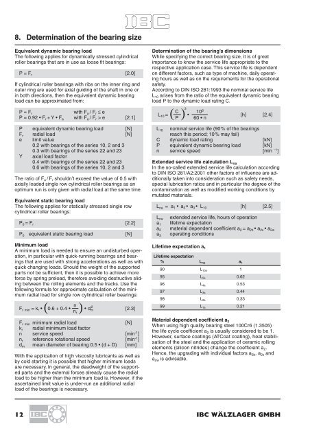
Lifetime expectation a 1<br />
Lifetime expectation<br />
% L na a 1<br />
90 L 10a 1<br />
95 L 5a 0.62<br />
96 L 4a 0.53<br />
97 L 3a 0.44<br />
98 L 2a 0.33<br />
99 L 1a 0.21<br />
Material dependent coefficient a 2<br />
When using high quality bearing steel 100Cr6 (1.3505)<br />
the life cycle coefficient a 2 is usually considered to be 1.<br />
However, surface coatings (ATCoat coating), heat stabilisation<br />
of the steel and the application of ceramic rolling<br />
elements (silicon nitrides) change the coefficient a 2 .<br />
Hence, the upgrading with individual factors a 2b , a 2s and<br />
a 2w is advisable.<br />
12 <strong>IBC</strong> WÄLZLAGER GMBH