where would we be without them? - Electrical Business Magazine
where would we be without them? - Electrical Business Magazine
where would we be without them? - Electrical Business Magazine

Create successful ePaper yourself
Turn your PDF publications into a flip-book with our unique Google optimized e-Paper software.
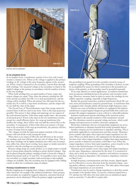
PHOTO 2<br />
PHOTO 1<br />
PHOTOS JUDITH HOWCROFT.<br />
In its simplest form<br />
In its simplest form, a transformer consists of two wire coils wound<br />
around a common core. When an AC voltage is applied to the primary<br />
winding, an AC voltage of the same frequency appears at the secondary.<br />
When a load is connected to the secondary, current flows through<br />
both windings. The measured voltage at the secondary is related to the<br />
applied voltage at the primary in accordance with the num<strong>be</strong>r of turns<br />
in the two windings.<br />
When both windings have an equal num<strong>be</strong>r of turns, input and<br />
output voltages are equal. Thus, when the primary winding has 100<br />
turns and the secondary has 200, it is a step-up transformer, and the<br />
voltage will <strong>be</strong> doubled. When the primary has 100 turns but the secondary<br />
has 50, it will <strong>be</strong> a step-down transformer, and the output will<br />
<strong>be</strong> one-half the value of the input.<br />
The Second Law of Thermodynamics states that energy cannot <strong>be</strong><br />
created <strong>where</strong> it did not exist in any form. How is this step-up process<br />
possible? The ans<strong>we</strong>r is that voltage and amperage are two aspects of<br />
the total electrical picture. Volts times amps equals watts—the measure<br />
of electrical po<strong>we</strong>r. Po<strong>we</strong>r is the same in the two transformer circuits,<br />
except for a small efficiency factor. In a step-up transformer that<br />
doubles the voltage, there will <strong>be</strong> only one-half the current flow in the<br />
secondary. A consequence of this is that when you connect a 10-amp<br />
load to the secondary of the step-up transformer, the primary will have<br />
to draw 20 amps from its supply.<br />
The voltages on both the input and output terminals of the transformer<br />
will each divide evenly among the turns.<br />
When there is an output of 100 volts and 100 turns in the secondary<br />
winding, each turn will have only one volt of voltage drop. This is<br />
why these windings can <strong>be</strong> lightly insulated; just a thin coat of enamel<br />
may suffice but, <strong>where</strong> layers overlap, heavy paper or similar material is<br />
needed so that the windings are not shorted out.<br />
Because voltage drops are evenly divided, it is a simple matter to install<br />
taps at various points along the winding to extract desired voltages. Taps<br />
can <strong>be</strong> placed along the primary winding to buck or boost the voltage in<br />
desired increments such as 5% and 10%. It is possible to have more than<br />
one secondary or a single secondary with several taps so that multiple<br />
voltages are available. Also, the secondary may <strong>be</strong> equipped with a sliding<br />
contact to allow for a continuous range of outputs.<br />
Putting transformers to work<br />
Besides stepping up or stepping down voltages, transformers perform<br />
other functions. An example is the isolation transformer. Since primary<br />
and secondary are coupled by magnetic induction, unwanted electrical<br />
parameters can <strong>be</strong> eliminated. When the primary supply is grounded,<br />
this grounding is not passed on to the secondary circuit by means of<br />
magnetic coupling. When grounding of the secondary is desired, it must<br />
<strong>be</strong> accomplished by means of a direct connection to the grounded conductor<br />
of the primary, or the secondary must <strong>be</strong> grounded separately.<br />
To <strong>be</strong> truly effective in critical applications, an isolation transformer<br />
must incorporate shielding <strong>be</strong>t<strong>we</strong>en the primary and secondary windings.<br />
Moreover, measures must <strong>be</strong> taken to ensure the windings do not<br />
exhibit capacitive coupling, especially at high frequencies.<br />
Besides the ground connection, isolation transformers block DC current,<br />
noise and interference caused by ground loops. A transformer that<br />
is equipped with a Faraday shield will attenuate high-frequency noise.<br />
Patient care areas of healthcare facilities are equipped with isolation<br />
transformers to guard against dangerous ground faults that could compromise<br />
life-support equipment or pose a threat to vulnerable patients.<br />
Isolation transformers permit rebonding of the electrical system<br />
safety ground to the neutral conductor of the transformer secondary.<br />
This eliminates neutral-to-ground voltage and noise, which could<br />
damage microprocessors in sensitive electronic equipment.<br />
Electronics technicians who are servicing faulty equipment use an isolation<br />
transformer to eliminate hazards from nearby grounded objects.<br />
Another common use for transformers is impedance matching. This is<br />
particularly applicable in communication and data circuits. Maximum<br />
po<strong>we</strong>r transfer takes place when input and output impedances are the<br />
same. When you think about it, the explanation for this phenomenon<br />
<strong>be</strong>comes clear; when output impedance is higher than input impedance,<br />
po<strong>we</strong>r transfer is limited in accordance with Ohm’s Law. When the<br />
output impedance is lo<strong>we</strong>r than input impedance, po<strong>we</strong>r transfer in the<br />
circuit is also limited <strong>be</strong>cause of excessive voltage drop.<br />
Maximum po<strong>we</strong>r transfer occurs when input and output impedances<br />
are the same. (Impedance, represented by the letter Z, is measured in<br />
ohms and is made up of resistance, capacitive and inductive reactances,<br />
which are frequency dependent. Like resistance, impedance conforms<br />
to Ohm’s Law.)<br />
In high-frequency communications and data circuits, digital signals<br />
can <strong>be</strong> reflected in a reverse direction from the intended output, causing<br />
packet collision, corruption and errors. This takes place when input<br />
and output impedances are not matched.<br />
Transformers may <strong>be</strong> used to change impedances so that they match.<br />
An example is the familiar balun. It converts a balanced signal from a<br />
TV antenna (on 300-ohm twin-lead cable) into an unbalanced signal<br />
such as carried by 75-ohm RG 6 coaxial cable.<br />
14 • March 2012 • www.EBMag.com