TAG-IN-A-BAG - Visonic Technologies
TAG-IN-A-BAG - Visonic Technologies
TAG-IN-A-BAG - Visonic Technologies

Create successful ePaper yourself
Turn your PDF publications into a flip-book with our unique Google optimized e-Paper software.
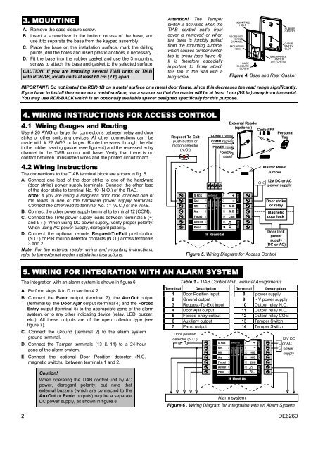
3. MOUNT<strong>IN</strong>G<br />
A. Remove the case closure screw.<br />
B. Insert a screwdriver in the bottom recess of the base, and<br />
use it to separate the base from the keypad assembly.<br />
C. Place the base on the installation surface, mark the drilling<br />
points, drill the holes and insert plastic anchors, if necessary.<br />
D. Fit the base into the rubber gasket and use the 3 mounting<br />
screws to attach the base and gasket to the selected surface<br />
CAUTION! If you are installing several TIAB units or TIAB<br />
with RDR-1B, locate units at least 60 cm (2 ft) apart.<br />
Attention! The Tamper<br />
switch is activated when the<br />
TIAB control unit’s front<br />
cover is removed or when<br />
the base is forcibly pulled<br />
from the mounting surface,<br />
which causes tamper switch<br />
tab to break (see figure 4).<br />
It is therefore especially<br />
important to firmly attach<br />
this tab to the wall with a<br />
long screw.<br />
Figure 4. Base and Rear Gasket<br />
IMPORTANT! Do not install the RDR-1B on a metal surface or a metal door frame, since this decreases the read range significantly.<br />
If you have to install the reader on a metal surface, use a spacer so that the reader will be at least 1 cm (3/8 in.) away from the metal.<br />
You may use RDR-BACK which is an optionally available spacer designed specifically for this purpose.<br />
4. WIR<strong>IN</strong>G <strong>IN</strong>STRUCTIONS FOR ACCESS CONTROL<br />
4.1 Wiring Gauges and Routing<br />
Use # 20 AWG or larger for connections between relay and door<br />
strike or other switching devices. All other connections can be<br />
made with # 22 AWG or larger. Route the wires through the slot<br />
in the rubber sealing gasket (see figure 4) and the recessed entry<br />
channel in the TIAB control unit base. Verify that there is no<br />
contact between uninsulated wires and the printed circuit board.<br />
4.2 Wiring Instructions<br />
The connections to the TIAB terminal block are shown in fig. 5.<br />
A. Connect one lead of the door strike to one of the hardware<br />
(door strike) power supply terminals. Connect the other lead<br />
of the door strike to terminal No. 10 (N.O.) of the TIAB.<br />
Note: If you are using a magnetic door lock, connect one of<br />
the leads to one of the hardware power supply terminals.<br />
Connect the other lead to terminal No. 11 (N.C.) of the TIAB.<br />
B. Connect the other power supply terminal to terminal 12 (COM).<br />
C. Connect the TIAB power supply leads between terminals 8 (+)<br />
and 9 (-). When using DC power supply, verify proper polarity.<br />
When using AC power supply, disregard polarity.<br />
D. Connect the optional remote Request-To-Exit push-button<br />
(N.O.) or PIR motion detector contacts (N.O.) across terminals<br />
3 and 2.<br />
Note: For the external reader wiring and mounting instructions,<br />
refer to the external reader installation instructions.<br />
Figure 5. Wiring Diagram for Access Control<br />
5. WIR<strong>IN</strong>G FOR <strong>IN</strong>TEGRATION WITH AN ALARM SYSTEM<br />
The integration with an alarm system is shown in figure 6.<br />
A. Perform steps A to D in section 4.2.<br />
B. Connect the Panic output (terminal 7), the AuxOut output<br />
(terminal 6), the Door Ajar output (terminal 4) and the Forced<br />
Entry output (terminal 5) to the appropriate zone of the alarm<br />
system, or to any other indicating device (relay, LED, buzzer,<br />
etc.). All these outputs are of the open collector type (see<br />
figure 7).<br />
C. Connect the Ground (terminal 2) to the alarm system<br />
ground terminal.<br />
D. Connect the Tamper terminals (13 & 14) to a 24-hour<br />
zone of the alarm system.<br />
E. Connect the optional Door Position detector (N.C.<br />
magnetic switch), between terminals 1 and 2.<br />
Request To Exit<br />
push-button or<br />
motion detector<br />
(N.O.)<br />
Table 1 - TIAB Control Unit Terminal Assignments<br />
Terminal Description Terminal Description<br />
1 Door Position input 8 V power supply<br />
2 Ground output 9 - V power supply<br />
3 Request-To-Exit input 10 Output relay N.O.<br />
4 Door Ajar output 11 Output relay N.C.<br />
5 Forced Entry output 12 Output relay COM<br />
6 Auxiliary output 13 Tamper Switch<br />
7 Panic output 14 Tamper Switch<br />
Door position<br />
detector (N.C.)<br />
◦ ◦<br />
External Reader<br />
(optional)<br />
Coded RF<br />
COMM 1 (white)<br />
COMM 2 (green)<br />
POWER + (red)<br />
POWER –<br />
(black)<br />
Personal<br />
Tag<br />
Master Reset<br />
Jumper<br />
12V DC or AC<br />
◦ ◦<br />
power supply<br />
Door strike<br />
or relay<br />
Magnetic<br />
door lock<br />
Door lock<br />
power<br />
supply<br />
(DC or AC)<br />
12V DC<br />
◦ or AC<br />
◦ power<br />
supply<br />
Caution!<br />
When operating the TIAB control unit by AC<br />
power, disregard polarity, but note that<br />
external buzzers (which are connected to the<br />
AuxOut or Panic outputs) require a separate<br />
DC power supply, as shown in figure 8.<br />
Alarm system<br />
Figure 6 . Wiring Diagram for Integration with an Alarm System<br />
2 DE6260