TAG-IN-A-BAG - Visonic Technologies
TAG-IN-A-BAG - Visonic Technologies
TAG-IN-A-BAG - Visonic Technologies

You also want an ePaper? Increase the reach of your titles
YUMPU automatically turns print PDFs into web optimized ePapers that Google loves.
<strong>TAG</strong>-<strong>IN</strong>-A-BAG <br />
Single door RF/ID Proximity Access Control Unit<br />
Installation and Programming<br />
1. <strong>IN</strong>TRODUCTION<br />
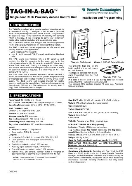
The TIAB (Tag-in-a-Bag) is a versatile weather-resistant proximity<br />
access control unit (fig. 1), designed to limit access to restricted<br />
areas, while permitting authorized people to enter. This product is<br />
the best in its class - using state-of-the-art proximity (non-contact)<br />
RF/ID technology. It was designed to serve your customers’<br />
needs, while making installation and use simple and easy.<br />
The TIAB control unit includes a keypad with an internal proximity<br />
reader and a display that provide full access control operation.<br />
The TIAB control unit can be programmed to offer one of two<br />
security levels for opening the door:<br />
• Level 1 (default): Valid tag only.<br />
• Level 2: Valid tag and P<strong>IN</strong> (Personal Identification Number)<br />
code.<br />
The TIAB control unit transmits 125 kHz RF signal. A valid<br />
proximity tag (fig. 3), presented to the control unit or to the<br />
optional external reader (fig. 2), transmits a coded RF signal back<br />
to the TIAB control unit, causing it to energize an output relay.<br />
The optional external reader is designed for installations in which<br />
an additional reader is required. It is connected to the TIAB<br />
control unit via 4 wires.<br />
The TIAB control unit is installed adjacent to the secured door’s<br />
frame. It is connected to the door’s EMS (Electro-Magnetic Strike)<br />
or magnetic lock and operates by either a 12V DC or AC power<br />
supply. The TIAB control unit includes internal non-volatile<br />
memory, unaffected by power failure. The internal memory stores<br />
data of up to 250 tags and P<strong>IN</strong> codes (used for security level 2<br />
only). Each P<strong>IN</strong> is composed of 4 digits.<br />
Figure 1. TIAB Keypad<br />
Figure 2. RDR-1B External Reader<br />
The proximity tags (fig. 3) are<br />
totally sealed and do not require<br />
any maintenance.<br />
The tags are powered from the RF<br />
signal transmitted from the TIAB<br />
control unit.<br />
Figure 3. <strong>TAG</strong>-1 Key<br />
In a case of loss or theft of a tag, the tag data can be easily<br />
deleted from the TIAB control unit memory list.<br />
The standard TIAB package includes 10 user tags. Additional<br />
tags are available.<br />
2. SPECIFICATIONS<br />
Power input: 12-16V DC or 9-12V AC<br />
Max. Current Consumption: 200 mA (excluding EMS current).<br />
Operating temperature: -20°C to 50°C (-4°F to 122°F).<br />
TIAB CONTROL UNIT<br />
Display: 2 x 7 segments and 3 LEDs.<br />
Buttons: 12 (numeric keypad).<br />
Memory capacity: 250 tag codes.<br />
Tag reading range: 50 - 100 mm (2 -4 in.)<br />
Internal tag reader frequency: 125 kHz.<br />
Tag codes possibilities: 10 12 possible combinations.<br />
Inputs:<br />
• Request-to-exit (N.O.), dry contact<br />
• Door position (N.C.), dry contact<br />
Outputs:<br />
• Lock relay N.O. / N.C. dry contact, 10A / 28V AC or DC<br />
• Door ajar / door held open (open collector output),<br />
100 mA max.<br />
• Panic (open collector output), 100 mA max.<br />
• Auxiliary (open collector output), 100 mA max.<br />
• Forced Entry (open collector output), 100 mA max.<br />
• Tamper (N.C. dry contact). Tamper switch is designed to<br />
detects attempts to open the unit, or remove it from the wall.<br />
NOTE: The total currents of all active open collector<br />
outputs should not exceed 200 mA.<br />
Size (H x W x D): 122 x 82 x 31 mm (4-13/16 x 3-1/2 x 1-1/4 in.)<br />
Weight: 170 g (6 oz) without the rubber gasket<br />
Color: Metallic brown<br />
<strong>TAG</strong>-1 PROXIMITY <strong>TAG</strong><br />
Size (L x W x D): 53 x 35 x 7 mm (2-1/8 x 1 3/8 x 9/32 in.)<br />
Weight: 5.5 g (0.2 oz).<br />
Color: Black<br />
<strong>TAG</strong>-10: Package of ten <strong>TAG</strong>-1 proximity tags<br />
RDR-1B EXTERNAL READER (optional)<br />
Indicators: Tri-color LED (green, red, amber).<br />
Tag reading range, tag reader frequency and tag codes<br />
possibilities: identical to Control Unit specification.<br />
Size: (L x W x D): 116 x 70 x 16.8 mm (2 3/4 x 4 1/2 x 5/8 in.)<br />
Weight: 121.5 g (4.3 oz)<br />
Cable (to TIAB control unit) maximum length: 10 m (32 ft.)<br />
TIAB-to-TIAB, RDR-1B-to-TIAB and RDR-1B-to-RDR-1B<br />
Minimum Distance: 60 cm (2 ft.).<br />
Color: Dark gray<br />
Compliance with standards: Complies with Part 15 of the FCC<br />
Rules and RSS-210 of Industry and Science Canada. Operation<br />
is subject to the following two conditions: (1) This device may not<br />
cause harmful interference, and (2) this device must accept any<br />
interference received, including interference that may cause<br />
undesired operation.<br />
DE6260 1
3. MOUNT<strong>IN</strong>G<br />
A. Remove the case closure screw.<br />
B. Insert a screwdriver in the bottom recess of the base, and<br />
use it to separate the base from the keypad assembly.<br />
C. Place the base on the installation surface, mark the drilling<br />
points, drill the holes and insert plastic anchors, if necessary.<br />
D. Fit the base into the rubber gasket and use the 3 mounting<br />
screws to attach the base and gasket to the selected surface<br />
CAUTION! If you are installing several TIAB units or TIAB<br />
with RDR-1B, locate units at least 60 cm (2 ft) apart.<br />
Attention! The Tamper<br />
switch is activated when the<br />
TIAB control unit’s front<br />
cover is removed or when<br />
the base is forcibly pulled<br />
from the mounting surface,<br />
which causes tamper switch<br />
tab to break (see figure 4).<br />
It is therefore especially<br />
important to firmly attach<br />
this tab to the wall with a<br />
long screw.<br />
Figure 4. Base and Rear Gasket<br />
IMPORTANT! Do not install the RDR-1B on a metal surface or a metal door frame, since this decreases the read range significantly.<br />
If you have to install the reader on a metal surface, use a spacer so that the reader will be at least 1 cm (3/8 in.) away from the metal.<br />
You may use RDR-BACK which is an optionally available spacer designed specifically for this purpose.<br />
4. WIR<strong>IN</strong>G <strong>IN</strong>STRUCTIONS FOR ACCESS CONTROL<br />
4.1 Wiring Gauges and Routing<br />
Use # 20 AWG or larger for connections between relay and door<br />
strike or other switching devices. All other connections can be<br />
made with # 22 AWG or larger. Route the wires through the slot<br />
in the rubber sealing gasket (see figure 4) and the recessed entry<br />
channel in the TIAB control unit base. Verify that there is no<br />
contact between uninsulated wires and the printed circuit board.<br />
4.2 Wiring Instructions<br />
The connections to the TIAB terminal block are shown in fig. 5.<br />
A. Connect one lead of the door strike to one of the hardware<br />
(door strike) power supply terminals. Connect the other lead<br />
of the door strike to terminal No. 10 (N.O.) of the TIAB.<br />
Note: If you are using a magnetic door lock, connect one of<br />
the leads to one of the hardware power supply terminals.<br />
Connect the other lead to terminal No. 11 (N.C.) of the TIAB.<br />
B. Connect the other power supply terminal to terminal 12 (COM).<br />
C. Connect the TIAB power supply leads between terminals 8 (+)<br />
and 9 (-). When using DC power supply, verify proper polarity.<br />
When using AC power supply, disregard polarity.<br />
D. Connect the optional remote Request-To-Exit push-button<br />
(N.O.) or PIR motion detector contacts (N.O.) across terminals<br />
3 and 2.<br />
Note: For the external reader wiring and mounting instructions,<br />
refer to the external reader installation instructions.<br />
Figure 5. Wiring Diagram for Access Control<br />
5. WIR<strong>IN</strong>G FOR <strong>IN</strong>TEGRATION WITH AN ALARM SYSTEM<br />
The integration with an alarm system is shown in figure 6.<br />
A. Perform steps A to D in section 4.2.<br />
B. Connect the Panic output (terminal 7), the AuxOut output<br />
(terminal 6), the Door Ajar output (terminal 4) and the Forced<br />
Entry output (terminal 5) to the appropriate zone of the alarm<br />
system, or to any other indicating device (relay, LED, buzzer,<br />
etc.). All these outputs are of the open collector type (see<br />
figure 7).<br />
C. Connect the Ground (terminal 2) to the alarm system<br />
ground terminal.<br />
D. Connect the Tamper terminals (13 & 14) to a 24-hour<br />
zone of the alarm system.<br />
E. Connect the optional Door Position detector (N.C.<br />
magnetic switch), between terminals 1 and 2.<br />
Request To Exit<br />
push-button or<br />
motion detector<br />
(N.O.)<br />
Table 1 - TIAB Control Unit Terminal Assignments<br />
Terminal Description Terminal Description<br />
1 Door Position input 8 V power supply<br />
2 Ground output 9 - V power supply<br />
3 Request-To-Exit input 10 Output relay N.O.<br />
4 Door Ajar output 11 Output relay N.C.<br />
5 Forced Entry output 12 Output relay COM<br />
6 Auxiliary output 13 Tamper Switch<br />
7 Panic output 14 Tamper Switch<br />
Door position<br />
detector (N.C.)<br />
◦ ◦<br />
External Reader<br />
(optional)<br />
Coded RF<br />
COMM 1 (white)<br />
COMM 2 (green)<br />
POWER + (red)<br />
POWER –<br />
(black)<br />
Personal<br />
Tag<br />
Master Reset<br />
Jumper<br />
12V DC or AC<br />
◦ ◦<br />
power supply<br />
Door strike<br />
or relay<br />
Magnetic<br />
door lock<br />
Door lock<br />
power<br />
supply<br />
(DC or AC)<br />
12V DC<br />
◦ or AC<br />
◦ power<br />
supply<br />
Caution!<br />
When operating the TIAB control unit by AC<br />
power, disregard polarity, but note that<br />
external buzzers (which are connected to the<br />
AuxOut or Panic outputs) require a separate<br />
DC power supply, as shown in figure 8.<br />
Alarm system<br />
Figure 6 . Wiring Diagram for Integration with an Alarm System<br />
2 DE6260
Figure 7 - “Open collector” Output Connection to an Alarm System<br />
6. PROGRAMM<strong>IN</strong>G<br />
6.1 General Description<br />
The TIAB control unit recognizes a single 4-digit master code<br />
which is used for all programming modes. This code<br />
accompanies a tag which is defined as the master tag.<br />
When first powering-up the Tag-in-a-Bag system:<br />
If the display blinks “00” and the green LED flashes, present a<br />
tag close to the keypad. When the display shows “Cd”, enter a<br />
4-digit P<strong>IN</strong> code and press “#”. This defines the presented tag<br />
as a Master-tag, used for programming. Then proceed to<br />
program the system (Section 6.3).<br />
Reprogramming can be done as many times as necessary, but<br />
for security reasons it is restricted to the master tag holder.<br />
Important:<br />
1. The person in charge must have an updated list which<br />
includes up to 250 tags holders names and the P<strong>IN</strong> code<br />
assigned to each of the tags. The table attached to the<br />
TIAB User Guide may be used.<br />
2. The master tag should be used for programming only and<br />
must be kept in a safe place!<br />
An existing code must be deleted first if a new code is to be<br />
saved in the same memory address.<br />
Note: The TIAB control unit reverts to normal mode after a 30<br />
second non-activity timeout, or if “” is pressed.<br />
While waiting for the programmer’s selection, the internal buzzer<br />
continuously sounds short beeps.<br />
6.2 Master Tag Programming<br />
Remove jumper → Buzzer beeps and stops<br />
Reinstall jumper 8422<br />
# <br />
P<strong>IN</strong> code #<br />
Important! The TIAB control unit does NOT operate unless a<br />
valid master tag and master code have been programmed.<br />
A. Remove the Master Reset Jumper (fig. 5). The TIAB buzzer<br />
will start beeping.<br />
B. Once the buzzer stops beeping, re-install the jumper and,<br />
within 10 seconds, key in the master code “8422” followed<br />
by “#”. As a result, the TIAB control unit will go into the<br />
ADD mode (blinking green LED) and and will display the<br />
master code memory address - flashing “00”.<br />
C. Place the tag, assigned as the master tag, within range of<br />
the keypad. The buzzer will beep twice and the display will<br />
show “Cd” (Code).<br />
D. Key in the desired master P<strong>IN</strong> code (4 digits) and then<br />
press “#”. The programming of the master tag code is<br />
completed and the unit returns to normal position.<br />
6.3 Entering/Quitting the Programming<br />
Mode<br />
Note: For programming, the master tag and P<strong>IN</strong> code are<br />
always required, regardless of security level setting.<br />
Entering the Programming Mode<br />
Hold the master tag near the TIAB for at least<br />
10 seconds. After the yellow LED blinks and<br />
the buzzer sounds, key the master tag’s 4-digit<br />
P<strong>IN</strong> code. “Pr” (Programming) will blink in the display.<br />
Notes:<br />
1. The TIAB and the Control Panel must have a common ground.<br />
2. The Control Panel must be a common negative panel - the<br />
common / shared terminals between zones are 0V (-).<br />
9 (-)<br />
AUX (6) or PANIC (7)<br />
TIAB<br />
External<br />
buzzer<br />
Figure 8 - External Buzzer Connections to AuxOut or Panic<br />
Output When TIAB is Powered by AC Power Supply<br />
Quitting the Programming Mode<br />
Press “” to exit any of the programming mode options into<br />
the main programming mode. Press “” again to quit the main<br />
programming mode and revert to normal operation.<br />
TIAB’s Programming Modes Description<br />
Mode Mode Name Functions Indicator<br />
1 ADD (tags) Adding user tag Green<br />
2 REVIEW (codes) Viewing users codes Red<br />
3 DELETE (tags) Deleting user tags Yellow<br />
4 SETUP Modifying system parameters All LEDs<br />
6.4 Adding User Tags<br />
Security level 1: “Pr” mode<br />
<br />
<br />
Security level 2: “Pr” mode 1 P<strong>IN</strong> code #<br />
For detailed description, refer to the user’s guide, section 3.1.<br />
6.5 Reviewing User Tags<br />
1<br />
#<br />
<br />
“Pr” mode<br />
2<br />
For detailed description, refer to the user’s guide section 3.2.<br />
6.6 Deleting an Existing User Tag<br />
12VDC<br />
power<br />
supply<br />
“Pr” mode<br />
3 <br />
# #<br />
or<br />
“Pr” mode<br />
<br />
3 <strong>TAG</strong> Address # # #<br />
For detailed description, refer to the user’s guide section 3.3.<br />
Note: Deleting information in address 000 invalidates the master<br />
tag. For re-programming the master tag, refer to section 6.2.<br />
6.7 Setup Mode<br />
Setup mode enables to determine how the TIAB reacts in various<br />
situations. In programming mode (“Pr” is displayed) press “4” to<br />
select the functions setup mode. All the 3 LED’s continuously<br />
blink and the display is blank. In this state, the installer can select<br />
one of seven functions to modify the setup, as detailed in the<br />
function setup table.<br />
Programming steps in the SETUP mode:<br />
“Pr” mode<br />
<br />
Function 1-7 #<br />
A. Press the number that corresponds to the desired function (1-7).<br />
B. The TIAB control unit displays the two letters corresponding to<br />
the function (see functions setup table).<br />
C. Press “#” to enter the functions selection mode.<br />
D. The TIAB control unit displays the current value for the<br />
selected function.<br />
E. To accept the existing value, press “#”. To return to the<br />
function setup selection, press “”. To change the existing<br />
value, enter the new value followed by pressing “#”.<br />
+−<br />
4 New value #<br />
DE6260 3
Table 2 - Function Setup Table<br />
Func. Description Enter Default Display<br />
1 Door unlock duration or toggle<br />
mode (see note 3).<br />
01-98 sec.<br />
99 = toggle<br />
mode<br />
05<br />
sec.<br />
2 Door Position input. Set Door 01-99 00<br />
Ajar alarm timeout of opened seconds<br />
door to 01-99 seconds or 00 = disable<br />
disable (00) - see note 6. door input<br />
3 Auxiliary Output.<br />
(see notes 1, 6 and table 3).<br />
0 - 7 0<br />
4 Ambush Digit - Fifth digit<br />
entered after P<strong>IN</strong> code for<br />
signaling a duress situation.<br />
(see notes 2, 6)<br />
5 Security Level (see notes 4, 5)<br />
1 = No P<strong>IN</strong> code required.<br />
2 = P<strong>IN</strong> code is required.<br />
6 Buzzer feedback control.<br />
0= No buzzer feedback.<br />
1= Buzzer beeps when button<br />
is pressed.<br />
7 Buzzer's Indication that the<br />
door is left open.<br />
0 = No buzzer operation.<br />
1 = Buzzer beeps if door is left<br />
open longer than defined in<br />
function 2.<br />
0-9<br />
00 = disable<br />
00<br />
1 or 2 1<br />
0 or 1 1<br />
0 or 1 0<br />
Notes:<br />
1. If the Auxiliary output is enabled, it operates for all tags.<br />
2. Ambush Digit is applicable for security level 2: Ambush Digit is<br />
the fifth digit added to the user P<strong>IN</strong> code. If the user is forced<br />
to enter under threat, pressing the Ambush digit after the last<br />
digit of the P<strong>IN</strong> code activates the Panic output.<br />
3. In the Toggle mode, presenting a valid tag/code turns the<br />
output on and presenting it again turns the output off.<br />
4. When selecting security level 1 (no P<strong>IN</strong> code required) it is still<br />
possible to enter a P<strong>IN</strong> code for each tag, during<br />
programming. However, in normal operation the TIAB will not<br />
prompt the user for the P<strong>IN</strong> code.<br />
5. Selecting security level 1 does not affect the master tag. The<br />
master tag always requires a P<strong>IN</strong> code.<br />
6. Disabling a function by 00, will show − − on the display.<br />
IMPORTANT! If you are not using a door position detection<br />
switch, be sure to set “dP’ to “00” and “Ob” to 0. This will<br />
prevent a continuous “Door Ajar” alert.<br />
Table 3 - Auxiliary Output Modes<br />
Setting<br />
Auxiliary Output Description<br />
0 Disabled.<br />
1 Triggered for 1 second.<br />
2 Toggled (latch/unlatch).<br />
3 Operated together with relay timer (function 1), but<br />
stays on for 5 seconds more. If toggle mode has been<br />
selected (function 1 - see table 2), the auxiliary output<br />
does not change state each time the relay is toggled.<br />
4 Latches when a valid tag is presented and resets by<br />
pressing “”.<br />
5 Turns on for 10 seconds, by pressing any button.<br />
6 Triggered after 3 consecutive invalid keys are<br />
presented or 3 consecutive invalid P<strong>IN</strong>s are entered.<br />
The output is triggered once a second for 10 minutes<br />
and may be reset only by entering a user code no<br />
sooner than 30 seconds after being tripped.<br />
7 Turned on by pressing “1” and “3” simultaneously.<br />
7. SYSTEM NORMAL OPERATION AND FUNCTIONAL TEST<br />
7.1 Normal Operation<br />
Normal operation is the mode in which the door lock is opened<br />
when a valid tag is presented to the reader (in security level 2,<br />
followed by valid user P<strong>IN</strong>).<br />
The TIAB control unit can use the internal reader or an optional<br />
external reader to read proximity tags.<br />
Pressing “” and “#” simultaneously activates the Panic output<br />
for 5 seconds. In this case, the buzzer does not beep.<br />
The LEDs functions in normal operation are summarized in the<br />
next table.<br />
LEDs functions in normal operation<br />
LED<br />
Function<br />
GREEN Indicates that the door is opened.<br />
◦<br />
RED Indicates that an invalid tag was presented or an invalid P<strong>IN</strong><br />
◦<br />
was entered.<br />
YELLOW Remains lit to indicate that the power is on. In security level<br />
◦<br />
2, blinks after a tag is accepted, to prompt the user for P<strong>IN</strong>.<br />
Time Out<br />
A delay of more than 5 seconds, between presenting a tag and<br />
starting to key user P<strong>IN</strong> code, or between any two digits, cancels<br />
the operation.<br />
If you enter three consecutive wrong codes, the TIAB control unit<br />
will be disabled for 30 seconds and the buzzer will beep rapidly.<br />
7.2 System Functional Test<br />
A. Supply power to the TIAB control unit and verify that the<br />
yellow LED lights steadily, to indicate that the power is ON.<br />
B. Enter the TEST mode (see section 4 of user’s guide) and<br />
verify proper function of the TIAB keypad, display and buzzer.<br />
For security level 1 only<br />
C. Present a valid tag at a distance of 50 - 100 mm (2 - 4 in.)<br />
from the keypad (or external reader) and verify that all the<br />
functions are performed as programmed. Verify also that<br />
when the door is opened the green LED is illuminated.<br />
D. Verify that when an invalid tag is presented the buzzer<br />
sounds and the red LED illuminates.<br />
For security level 2 only<br />
E. Present valid tag at distance of 50 - 100 mm (2 - 4 in.) from<br />
the keypad (or external reader).<br />
F. Verify that the yellow LED light starts blinking after tag<br />
presentation, to prompt the user to enter P<strong>IN</strong> code.<br />
G. Enter the user code followed by the ambush digit. The PANIC<br />
output should be activated, if ambush option is enabled.<br />
H. Verify that when presenting an invalid tag, entering an invalid<br />
code, or both, the red LED illuminates and the buzzer sounds.<br />
For both security levels<br />
I. Verify that all the user tags enable the opening of the door.<br />
J. Verify that pressing “” and “#” simultaneously activates the<br />
panic output for 5 seconds.<br />
This device complies with the essential requirements and provisions of Directive 1999/5/EC of the European Parliament and of the Council of 9 March 1999 on radio and<br />
telecommunications terminal equipment..<br />
VISONIC TECHNOLOGIES. (ISRAEL): 30 Habarzel St. Tel Aviv 69710 ISRAEL Tel 972-3-7681400 Fax: 972-3-7681415 E-MAIL: support@visonictech.com<br />
VTA (VISONIC TECHNOLOGIES AMERICAS): 65 West Dudley Town Road, Bloomfield CT. 06002-1911 USA. TEL.: (860) 243 0833, (800) 223 0020<br />
FAX: (860) 242-8094.<br />
E-MAIL: usa_support@visonic.com<br />
VT UK (VISONIC TECHNOLOGIES UK): Fraser Road, Priory Business Park, Bedford MK44 3WH ENGLAND. TEL.: 44-870-730-0840; FAX: 44-870-730-0839<br />
<strong>IN</strong>TERNET: www.visonictech.com<br />
4 DE6260
©VISONIC TECHNOLOGIES LTD. 2004 <strong>TAG</strong>-<strong>IN</strong>-A-BAG DE6260- (REV. 3, 10/04) Refer to warranty statement in the User Guide.<br />
DE6260 5