ST-12 Manual - Innovate Motorsports
ST-12 Manual - Innovate Motorsports
ST-12 Manual - Innovate Motorsports

You also want an ePaper? Increase the reach of your titles
YUMPU automatically turns print PDFs into web optimized ePapers that Google loves.
<strong>ST</strong>-<strong>12</strong><br />
SuperTune <strong>12</strong> Engine Data Acquisition System<br />
Warning!<br />
The Oxygen Sensor used in this device gets very hot in operation. Do not touch the hot sensor.<br />
Do not let a hot sensor touch a combustible surface. Do not use the sensor with or near<br />
flammable liquids or gases. Failure to heed these warnings may result in severe burns,<br />
explosions or fires.<br />
When installed in the exhaust, the oxygen sensor MU<strong>ST</strong> be connected and operating with the <strong>ST</strong>-<br />
<strong>12</strong> whenever the car is running. An un-powered oxygen sensor will be quickly damaged when<br />
exposed to hot exhaust gases.<br />
<strong>ST</strong><strong>12</strong>_<strong>Manual</strong>_1.1.doc
1 Overview ...............................................................................................................................................................3<br />
2 The SuperTune-<strong>12</strong> (<strong>ST</strong>-<strong>12</strong>)...................................................................................................................................4<br />
3 First Time Use.......................................................................................................................................................5<br />
3.1 Launching and connecting LogWorks..........................................................................................................5<br />
3.2 Connecting the LC-1<strong>ST</strong> to the <strong>ST</strong>-<strong>12</strong> and Calibration .................................................................................6<br />
3.3 Selecting internal sensors. ...........................................................................................................................7<br />
4 LC-1<strong>ST</strong>..................................................................................................................................................................8<br />
4.1 Calibration ....................................................................................................................................................8<br />
4.2 Free air calibration........................................................................................................................................8<br />
4.3 Sensor heater calibration .............................................................................................................................9<br />
4.4 Sensor Location ...........................................................................................................................................9<br />
4.5 HBX-1.........................................................................................................................................................11<br />
4.6 Programming the LC-1<strong>ST</strong> ..........................................................................................................................11<br />
4.6.1 Resetting the calibration data ................................................................................................................<strong>12</strong><br />
4.6.2 Updating the Firmware...........................................................................................................................<strong>12</strong><br />
4.6.3 Programming the analog outputs...........................................................................................................<strong>12</strong><br />
4.6.4 Advanced output programming..............................................................................................................13<br />
5 Internal Sensors..................................................................................................................................................14<br />
5.1 Connecting Type K Thermocouples...........................................................................................................14<br />
5.2 Connecting an RPM signal.........................................................................................................................15<br />
5.2.1 Using the Variable Potentiometer ..........................................................................................................15<br />
5.2.2 RPM Measurement basics.....................................................................................................................15<br />
5.2.3 Four-Stroke Engines ..............................................................................................................................16<br />
5.2.4 Two-Stroke Engines...............................................................................................................................16<br />
5.2.5 Rotary Engines (Wankel Engine)...........................................................................................................16<br />
5.2.6 How the <strong>ST</strong>-<strong>12</strong> determines RPM ...........................................................................................................16<br />
5.2.7 Programming the RPM input..................................................................................................................17<br />
5.2.8 Using the <strong>ST</strong>-<strong>12</strong> with the Inductive Clamp.............................................................................................18<br />
5.2.9 Inductive Clamp Usage..........................................................................................................................18<br />
5.2.10 Using the RPM-Converter with pulsed RPM input (Tach) signals.....................................................19<br />
5.3 Measuring Pressures .................................................................................................................................19<br />
5.3.1 Measuring MAP .....................................................................................................................................19<br />
5.3.2 Measuring boost/vacuum.......................................................................................................................19<br />
5.4 Measuring Ignition Advance.......................................................................................................................20<br />
5.4.1 Making your own optical reference pulse sensor ..................................................................................22<br />
5.5 Measuring Frequencies, custom RPM, or speed.......................................................................................23<br />
5.6 Measuring duty cycle..................................................................................................................................24<br />
6 Programming the <strong>ST</strong>-<strong>12</strong>......................................................................................................................................24<br />
6.1 Changing the device name ........................................................................................................................25<br />
6.2 Updating the firmware ................................................................................................................................25<br />
6.3 Input 1 Configuration..................................................................................................................................25<br />
6.3.1 Measuring RPM .....................................................................................................................................26<br />
6.3.2 Measuring Frequency ............................................................................................................................27<br />
6.3.3 Measuring Speed...................................................................................................................................27<br />
6.3.4 Duty cycle ..............................................................................................................................................28<br />
6.4 Input 2 Configuration..................................................................................................................................28<br />
6.5 Input 3 configuration...................................................................................................................................28<br />
6.6 Input 4 configuration...................................................................................................................................29<br />
6.7 Input 5 configuration...................................................................................................................................29<br />
7 Appendix .............................................................................................................................................................30<br />
7.1 Error Codes ................................................................................................................................................30<br />
7.2 LED Blinking Codes ...................................................................................................................................31<br />
7.3 <strong>ST</strong>-<strong>12</strong> Do’s and Don’ts ...............................................................................................................................32<br />
8 Revision History ..................................................................................................................................................33<br />
2
1 Overview<br />
The SuperTune-<strong>12</strong> is a complete data acquisition system for advanced engine tuning. The system is<br />
capable of logging up to <strong>12</strong> Air/Fuel channels and also includes flexible sensors for RPM, MAP,<br />
Temperature, Duty Cycle, and analog inputs.<br />
The <strong>ST</strong>-<strong>12</strong> can power, manage, and consolidate data from up to <strong>12</strong> specialized LC-1<strong>ST</strong>s (Lambda<br />
Cable) wideband oxygen sensor controller cables. The specialized cables are functionally identical to the<br />
standard LC-1<strong>ST</strong> cables, except they are 18 ft. long, terminated with a single <strong>ST</strong>-<strong>12</strong> (DB-15) connector,<br />
and sleeved in a rugged thermal insulator.<br />
The <strong>ST</strong>-<strong>12</strong>’s LC-1<strong>ST</strong> is a Wideband Controller used to measure the Air/Fuel Ratio (AFR) or Lambda for<br />
an engine. For gasoline-driven engines, the theoretically optimal air fuel ratio is 14.7 pounds of air for<br />
every pound of fuel. At this ratio, theoretically, all available oxygen in the air combines with all available<br />
fuel. This ratio is called the stoichiometric ratio. Stoichiometric for different fuels are as follows:<br />
Gasoline 14.7<br />
LPG (Propane) 15.5<br />
Methanol 6.4<br />
Ethanol 9.0<br />
CNG 17.2<br />
Diesel 14.6<br />
The measurement Lambda is the actual air fuel ratio over the stoichiometric ratio. A Lambda<br />
measurement of “1” equates to the air fuel ratio of 14.7 (for gasoline engines). When Lambda is less<br />
than 1 the engine runs “rich”, i.e., unburned fuel exists in the exhaust stream. If lambda is greater than 1<br />
the engine runs lean, i.e., free oxygen (0 2 ) is present in the exhaust. Depending on the engine, maximum<br />
power is typically delivered when the engine runs slightly rich (for example at lambda values of 0.8 to 0.9<br />
for most engines). This instrument provides a means to measure the actual air fuel ratio or lambda in the<br />
engine in operation directly from the exhaust. For this a special wide-band oxygen sensor is used to<br />
measure the lambda value derived from the oxygen content (or lack thereof) of the exhaust gases.<br />
3
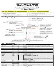
2 The SuperTune-<strong>12</strong> (<strong>ST</strong>-<strong>12</strong>)<br />
Front<br />
View<br />
ON/OFF<br />
switch<br />
Program functions such as RPM, MAP,<br />
Temperature, Duty Cycle, and analog inputs.<br />
RPM calibration number can also be<br />
programmed here.<br />
LED indicates LC-1<strong>ST</strong> conditions<br />
such as warming up, normal<br />
operation, or error codes.<br />
Push buttons trigger a Free Air<br />
Calibration on the LC-1<strong>ST</strong>s.<br />
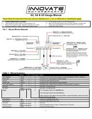
Rear View<br />
Digital connection from<br />
each individual LC-1<strong>ST</strong><br />
(wideband controller) to<br />
the DB-15 connector<br />
Inductive<br />
Clamp input<br />
Analog Inputs<br />
Power Supply<br />
On/Off switch<br />
Variable<br />
Potentiometer to<br />
adjust the RPM signal<br />
Serial In/Out<br />
Analog<br />
Outputs<br />
4
3 First Time Use<br />
Put the included CD in your CD-drive on your computer and follow the instructions on screen. The<br />
Software will be installed including pre-set directories for log-data and downloaded software. The LM<br />
Installer also puts entries for the LM Software in the Start-Menu of your computer under the heading<br />
‘<strong>Innovate</strong>!’.<br />
The following items will be installed on your hard-drive<br />
1. LM Programmer<br />
This is used to program the analog outputs of the LC-1<strong>ST</strong>, the fuel type used, the sensor type<br />
used, and also allows to ‘reflash’ the firmware of the LC-1<strong>ST</strong>.<br />
2. LogWorks<br />
This is a comprehensive data logging and analysis package. It also allows real-time logging and<br />
display.<br />
3.1 Launching and connecting LogWorks<br />
Connect the Serial OUT port of the <strong>ST</strong>-<strong>12</strong> to a free serial port on your computer and start the LogWorks<br />
program.<br />
The following dialog box will appear:<br />
Select the serial port (COM Port) to which the Log-Chain is connected. Then press the Connect button.<br />
To quit here and don’t start LogWorks press the Quit button.<br />
If you do not wish to connect to the chain of sensors (or don’t have it connected), Press the “Don’t<br />
connect” button.<br />
Check the “Connect on this port in the future” checkbox if you want to auto-connect on the selected port<br />
always in the future (you can change that later on if you wish).<br />
LogWorks can also be started by dragging one or more log files on the LogWorks icon (if you installed<br />
one on the desktop). In this case the log files will be opened automatically.<br />
Make sure no other program (including LM Programmer) is using the selected serial port.<br />
5
3.2 Connecting the LC-1<strong>ST</strong> to the <strong>ST</strong>-<strong>12</strong> and Calibration<br />
Note: The calibration process can be done with multiple LC-1<strong>ST</strong>s<br />
at one time<br />
Connect the DB-15 connector from the LC-1<strong>ST</strong> to the <strong>ST</strong>-<strong>12</strong>.<br />
1 Do not connect the sensor to the LC-1<strong>ST</strong> yet.<br />
2 Switch ON the power supply on the <strong>ST</strong>-<strong>12</strong>. You should see the following<br />
screen in LogWorks:<br />
3 Switch off the power supply after 10 seconds.<br />
4 Connect the sensor to the sensor interface connector on the LC-1<strong>ST</strong>. The<br />
sensor must be exposed to free air (outside of the exhaust) for the<br />
first time calibration.<br />
5 Switch ON the power supply on the <strong>ST</strong>-<strong>12</strong>. After the sensor is warmed<br />
up, the LC-1<strong>ST</strong> automatically calibrates the sensor heater controller to<br />
the particular sensor. During this 20-second period the LC-1<strong>ST</strong> collects<br />
and calculates sensor specific data required to quickly reach operating temperature in the future.<br />
During the heater calibration the screen will show a “Htr Cal” count down<br />
from 9 to 0.<br />
6 Press the Calibration button for the LC-1<strong>ST</strong> on the front of the <strong>ST</strong>-<strong>12</strong>. The<br />
LC-1<strong>ST</strong> will now calibrate itself by using air as a reference gas with<br />
known oxygen content. After the calibration period is over (2-3 seconds),<br />
the instrument is ready to operate.<br />
In general, it’s only necessary to calibrate the sensor heater the first time you<br />
use a new sensor, while the free air calibration is required more frequently.<br />
Free air calibration will correct for: 1) A change in atmospheric pressure (i.e.<br />
going from sea level to 6,000 ft. above for a race); or 2) Sensor wear (i.e.<br />
regular use for hundreds of hours).<br />
Heater calibration detects and stores the impedance characteristics of a new sensor. Generally these<br />
characteristics don’t change with wear, however some forms of carbonization can impact the impedance<br />
of the sensor. The most common problematic carbonization comes from the use of leaded gas. If you see<br />
an error #4 (Pump cell circuit open) after using the sensor with leaded gas, you probably need to perform<br />
a heater recalibration. If you use sensor regularly with race gas, we recommend keeping a backup<br />
sensor, and performing heater recalibrations more frequently.<br />
6
The Heater Calibration and Free Air Calibration are unique to each sensor. If you use a<br />
different sensor on a LC-1<strong>ST</strong> you will need to run through the whole Calibration procedure again<br />
(section 3.2)!<br />
3.3 Selecting internal sensors.<br />
Table 1:<br />
Input<br />
Functio<br />
ns<br />
Input 1 Functions<br />
Function<br />
Indicator<br />
Functionality<br />
1 2 F d =<br />
RPM<br />
(0..10230)<br />
RPM<br />
(0..20460)<br />
Frequency<br />
(straight<br />
frequency,<br />
Speed<br />
sensor,<br />
Custom<br />
RPM range<br />
Duty Cycle<br />
External<br />
0..5V<br />
sensors<br />
Input 2 Functions<br />
Function 1 2 =<br />
Indicator<br />
Functionality Thermocouple<br />
EGT range<br />
(0..1093<br />
degC,<br />
32..1999<br />
degF)<br />
Thermocouple<br />
CHT range<br />
(0..300 degC,<br />
32..572 degF)<br />
External<br />
0..5V<br />
sensors<br />
Input 3 Functions<br />
Function 1 2 F =<br />
Indicator<br />
Functionality Duty Cycle Ignition<br />
Timing<br />
Frequency<br />
(straight<br />
frequency,<br />
Speed<br />
sensor,<br />
Custom<br />
RPM range<br />
External<br />
0..5V<br />
sensors<br />
7
Input 4 Functions<br />
Function 1 2 3 4 F d =<br />
Indicator<br />
Functionality MAP (1<br />
bar)<br />
(0..101.3<br />
kPa)<br />
MAP (3<br />
bar)<br />
(0..304.1<br />
kPa)<br />
Vacuum<br />
(0..30<br />
inHg<br />
Vacc)<br />
Vacuum/Boost<br />
(-14.7PSI…<br />
29.4 PSI)<br />
Frequency<br />
(straight<br />
frequency,<br />
Speed<br />
sensor,<br />
Custom<br />
RPM<br />
range<br />
Duty<br />
Cycle<br />
External<br />
0..5V<br />
sensors<br />
Input 5 Functions<br />
Function<br />
Indicator<br />
Functionality<br />
F d =<br />
Frequency<br />
(straight<br />
frequency,<br />
Speed<br />
sensor,<br />
Custom<br />
RPM<br />
range<br />
Duty<br />
Cycle<br />
External<br />
0..5V<br />
sensors<br />
To program an input channel, repeatedly press the ‘Channel’ button until the channel number to program<br />
appears on the <strong>ST</strong>-<strong>12</strong> digit display. Then repeatedly press the ‘Function’ button until the digit display<br />
shows the intended function. The digit display will switch rapidly between indicating the input channel<br />
number and the set function. The LEDs next to the channel and function buttons will indicate which value<br />
is being displayed.<br />
If the function selected is External input, the digit display shows a ‘=’.<br />
4 LC-1<strong>ST</strong><br />
4.1 Calibration<br />
There are two types of calibration for the LC-1<strong>ST</strong>: free air calibration and sensor heater calibration.<br />
Sensor heater calibration is automatically performed the first time a new sensor is used and the free air<br />
calibration can be triggered from the “calibrate” button in from of the <strong>ST</strong>-<strong>12</strong>.<br />
4.2 Free air calibration<br />
To achieve maximum precision, the LC-1<strong>ST</strong> and its sensor needs to be recalibrated frequently with the<br />
sensor outside of the exhaust.<br />
8
The sensor MU<strong>ST</strong> be operated in free air for calibration.<br />
Remove the oxygen sensor and expose the sensor to air (away from the exhaust) for calibration<br />
purposes:<br />
1 Connect the LC-1<strong>ST</strong> to the <strong>ST</strong>-<strong>12</strong> and switch it on.<br />
2 After the sensor has warmed up, press the pushbutton.<br />
If a LED indicator on the face of the <strong>ST</strong>-<strong>12</strong> will be off during the free air calibration.<br />
4.3 Sensor heater calibration<br />
If you change the sensor – either with a replacement sensor or a new type of sensor --, the heater circuit<br />
of the LC-1<strong>ST</strong> needs to be recalibrated as well. (See steps in chapter 3 'First Time Use'). The heater<br />
calibration data in the LC-1<strong>ST</strong> will be reset when the device is operated from <strong>ST</strong>-<strong>12</strong> without a sensor<br />
connected for at least 5 seconds. You can force a reset by doing this, and then recalibrate by turning the<br />
unit off, reconnecting the sensor, and turning the <strong>ST</strong>-<strong>12</strong> on.<br />
After the sensor is warmed up the <strong>ST</strong>-<strong>12</strong> automatically calibrates the sensor heater controller to the<br />
particular sensor. During this 20-second period the LC-1<strong>ST</strong> collects and calculates sensor-specific data<br />
required to quickly reach operating temperature in the future.<br />
Note: When using the Bosch Sensors the LC-1<strong>ST</strong> may perform multiple calibration passes. This is<br />
normal and need not cause concern. When it completes, the LC-1<strong>ST</strong> also will perform a free air<br />
calibration. Make sure the sensor is operating in free air for the heater and free air calibration.<br />
4.4 Sensor Location<br />
Using a bung is the preferred method for mounting the O 2 sensor for both catalytic and noncatalytic<br />
cars.<br />
On CATALYTIC CONVERTER equipped vehicles:<br />
Install the oxygen sensor’s bung upstream from the catalytic converter (a bung and plug is included in<br />
the LC-1<strong>ST</strong> kit). Any decent muffler or exhaust shop can do this for you. The wide-band oxygen<br />
sensor is then installed into the bung to take a reading. (Insert the plug into the bung when not in<br />
use). The bung must be installed in the exhaust pipe at the side or on top, NOT on the bottom<br />
of the exhaust pipe. Best position is between 10:00 and 2:00 position.<br />
On NON-CATALYTIC converter vehicles:<br />
You have the option with non-catalytic cars to also use a Bung as described above. Use of a bung is<br />
the preferred method for mounting the 0 2 sensor for both catalytic and non-catalytic cars.<br />
On TURBO CHARGED vehicles:<br />
9
Install the bung downstream from the turbo before the catalytic converter. The high exhaust pressure<br />
before the turbo interferes with the lambda measurement and the high exhaust temperatures<br />
encountered there can damage the sensor.<br />
Sensor placement before the turbo is not recommend because of negative effects caused<br />
by back pressure and high temperatures.<br />
Do NOT install the Bung below the 3 o'clock or 9 o'clock position. Condensation can form<br />
in the exhaust pipe and permanently damage the sensor. 6 o’clock is the absolute worst position<br />
to mount the sensor.<br />
Wide band oxygen sensors – like the one shipped optionally with the LC-1<strong>ST</strong> – are<br />
designed to work with unleaded gasoline. Using them with leaded gasoline will significantly<br />
reduce the lifespan of the sensor. The reduction is directly proportional to the metal content of<br />
the fuel. In most cases, a wide band sensor will provide accurate measurements somewhere<br />
between 50 hours and 500 hours with leaded fuel.<br />
WHEN IN<strong>ST</strong>ALLED IN THE EXHAU<strong>ST</strong>, THE OXYGEN SENSOR MU<strong>ST</strong> BE CONNECTED AND<br />
OPERATING WITH THE LC-1<strong>ST</strong> WHENEVER THE ENGINE IS RUNNING. AN UN-POWERED<br />
OXYGEN SENSOR WILL BE DAMAGED WHEN EXPOSED TO EXHAU<strong>ST</strong> GAS.<br />
The maximum temperature of the sensor at the bung (the sensor hexagon) should not<br />
exceed 500 o C or 900 o F. If these temperatures are exceeded in your application install the<br />
<strong>Innovate</strong> <strong>Motorsports</strong>’ Heat-Sink Bung extender (HBX-1).<br />
The bung extender is recommended for situations where airflow is restricted or the encountered<br />
heat is higher than a heat sink can handle.<br />
Depending on the climate and the sensor position in the exhaust, condensation water can<br />
form in the exhaust pipes. This condensation water could then be blown by the exhaust stream<br />
against the hot sensor when the car is started. The resulting heat shock can permanently damage<br />
the sensor.<br />
10
4.5 HBX-1<br />
It is highly recommended that on high output engines, or engines<br />
running on race gas (leaded fuel) use the HBX-1 accessory on each<br />
sensor.<br />
4.6 Programming the LC-1<strong>ST</strong><br />
You must program each LC-1<strong>ST</strong> individually. You can accomplish this by plugging in each LC-1<strong>ST</strong> to the<br />
DB-15 connector in a backwards order. For example, if you need to program eight LC-1<strong>ST</strong>s you would<br />
connect the LC-1<strong>ST</strong> going into cylinder #8 into the 8 connector and program it first. Once you finish<br />
programming the LC-1<strong>ST</strong> you will need to cycle power (turn off the <strong>ST</strong>-<strong>12</strong> then turn it back on) and move<br />
on to the LC-1<strong>ST</strong> in cylinder # 7 so on an so forth until you reach the last LC-1<strong>ST</strong> in cylinder # 1.<br />
Make sure no other program (including LM Programmer or LM-1 Manager) is using the<br />
selected serial port.<br />
Start the LM-Programmer software. The screen should look like this:<br />
On this page you can see the software version of the LC-1<strong>ST</strong> and you can change the multiplier to<br />
calculate AFR from Lambda. A number of different multipliers are already pre-selectable but you can<br />
change it to a custom one for the particular fuel you are using.<br />
11
If you plan to use multiple LC-1<strong>ST</strong>’s, change the device name to something identifying which LC-1<strong>ST</strong> is<br />
connected where. For example LC1-Cyl1 for a LC1 connected to Cylinder 1. The device name can be up<br />
to 8 characters long.<br />
4.6.1 Resetting the calibration data<br />
Press the Reset Calibration button if you want to reset all calibration data in the LC-1<strong>ST</strong>.<br />
This will clear all calibration data of the LC-1<strong>ST</strong>.<br />
4.6.2 Updating the Firmware<br />
Click the 'Update Firmware' in the main page to upgrade to the latest firmware for the LC-1<strong>ST</strong>. Firmware<br />
for the LC-1<strong>ST</strong> has the extension dld. You can also download the latest firmware and software (LM<br />
Programmer and Demo) from the <strong>Innovate</strong>! <strong>Motorsports</strong> web-site at<br />
http://www.tuneyourengine.com<br />
If your computer crashes during a firmware upgrade, the LC-1<strong>ST</strong> has a recovery mechanism where it will<br />
be able to retry the download again and not be disabled by half loaded firmware. Switch the LC-1<strong>ST</strong> off<br />
and on again and then try to restart the LC1 Manager software. The recovery mechanism is designed to<br />
be able to recover 99.9% of the time. While we don’t anticipate this occurring, it is possible that the LC-<br />
1<strong>ST</strong> will not recover correctly and may need to be serviced at our factory. If you suspect this is the case,<br />
contact <strong>Innovate</strong> support.<br />
4.6.3 Programming the analog outputs<br />
Select one of the Analog output tabs. The Analog output page looks like this:<br />
<strong>12</strong>
This shows the analog output voltages versus Lambda for one of the two analog outputs. The graph<br />
display is automatically scaled to the selected voltages. For each output you can specify a minimum and<br />
maximum lambda value and the associated voltages. Below the minimum and above the maximum<br />
lambda values the output voltages stay constant at the associated programmed voltage.<br />
By selecting the ‘use Air-Fuel-Ratio’ button you can program the curve by AFR instead of<br />
Lambda. This does not change the programming, only the representation of the data. When<br />
programming by AFR the LM Programmer converts the number to Lambda before programming<br />
the LC-1<strong>ST</strong>.<br />
Click the Program button to download the new data into the LC-1<strong>ST</strong>.<br />
As factory programmed the first output simulates a typical narrow band oxygen sensor. The second<br />
output is programmed to output between 0 V for an AFR of 7.35 (gasoline) and 5.0V for an AFR of 22.39.<br />
Other curves of course are easily programmable<br />
4.6.4 Advanced output programming<br />
The normal state of the analog outputs is to update the outputs every time the LC-1<strong>ST</strong> takes a new<br />
measurement. The LC-1<strong>ST</strong> is fast enough to distinguish individual pockets of exhaust gas. For many<br />
applications this will be too fast. The advanced programming allows to set the analog out update speed.<br />
Press the “Advanced button” to set the advanced analog out settings. The following dialog box will<br />
appear:<br />
When setting the LC-1<strong>ST</strong> to the slower response speed settings the measured mixture data will be<br />
averaged over the response time setting before being output.<br />
You can also specify what output voltage is visible on the analog outputs during warm-up of the sensor<br />
and during error conditions.<br />
The ‘High Impedance’ setting allows to specify that the analog outputs do not drive the output during<br />
warm-up or error condition. They will be free floating. This is important for more closely simulating a<br />
narrow band sensor. Many EFI systems monitor the impedance of a narrow band sensor during engine<br />
warm-up to determine sensor readiness. A narrow band sensor that’s too cold will have a high<br />
impedance.<br />
13
5 Internal Sensors<br />
The <strong>ST</strong>-<strong>12</strong> can be programmed directly through the setup buttons on the <strong>ST</strong>-<strong>12</strong>. LM Programmer<br />
software version 3.05 (or later) allows you to program the <strong>ST</strong>-<strong>12</strong> via the LM Programmer software. This<br />
is necessary for some of the more advanced functionality of the <strong>ST</strong>-<strong>12</strong>. Some of these advanced<br />
functions like speed sensing, frequency sensing, custom RPM, ignition advance and so on require more<br />
user input data that cannot be supplied by the simple 3-button interface of the <strong>ST</strong>-<strong>12</strong>.<br />
5.1 Connecting Type K Thermocouples<br />
Thermocouples are used to measure temperatures by relying on the phenomena where a junction of any<br />
two different metals ( Copper and Iron, for example ) will generate a small voltage. This voltage is<br />
dependant upon which two metal are used, and the temperature of the junction. This phenomena is<br />
known, formally, as the "Seebeck Effect". Because every junction of different metals contributes its own<br />
voltage into the measurement, it is important to have as few junctions between dissimilar metals as<br />
possible in order to record an accurate measurement. This is why thermocouple wire is made completely<br />
of two different metals. The "Type K" thermocouple included in the <strong>ST</strong>-<strong>12</strong> kit is composed of Cromel and<br />
Alumel; one lead being made of each ( the red and yellow leads ). Do not look in the box for a<br />
thermocouple sensor to put onto the end of the thermocouple wire. You can use the wire AS the<br />
sensor or use the wires to attach to a Type K thermocouple.<br />
To make a thermocouple, strip approximately 3/4" of insulation form one end of the thermocouple wire.<br />
Twist the two exposed metal ends together. You may optionally solder them, also. But twist them<br />
first. Do not solder them in parallel. This will form what is called the "Hot junction". This "Hot junction" is<br />
what you will connect to the surface that you want to measure. This is usually either: a) under the copper<br />
gasket of a sparkplug for cylinder head temperature (CHT) or, b) clamped to a primary header tube for<br />
exhaust gas temperature (EGT).<br />
There is also the "Cold junction." This is where the 2 leads of the thermocouple come together again at<br />
the <strong>ST</strong>-<strong>12</strong> terminals. The <strong>ST</strong>-<strong>12</strong> has an internal temperature sensor at the T/C input terminals. It uses<br />
this sensor to "offset" the effect of the "Cold junction" in the measurement. This is called "Cold junction<br />
compensation". Once the effects of the cold junction are neutralized, the <strong>ST</strong>-<strong>12</strong> can accurately read the<br />
temperature of the "Hot junction" which is the twisted lead pair at the opposite end of the thermocouple<br />
wire.<br />
One thing that is confusing for many people is that the negative side of a thermocouple wire is always<br />
red. There are many different types of thermocouple wire; types K, J and T being the most popular. All<br />
have a red negative lead and a yellow, black, or blue positive lead respectively. When connection the<br />
thermocouple to the TC terminals on the <strong>ST</strong>-<strong>12</strong>, be sure to connect the yellow lead to the + and<br />
red lead to the - terminals.<br />
Several manufacturers offer EGT "thermocouple probes" which are actually inserted into the exhaust gas<br />
stream through a hole in the headers or exhaust manifold. These provide a more accurate measurement<br />
of exhaust gas temperature. They are commonly available in types K and J. Only type K will currently<br />
work with the <strong>ST</strong>-<strong>12</strong>. To use a thermocouple probe, connect the red and yellow leads of the<br />
thermocouple wire to the yellow and red leads of the thermocouple probe. The junction is inside the<br />
probe. You can not use normal copper wire to connect the thermocouple probe to the <strong>ST</strong>-<strong>12</strong>. You<br />
14
must use thermocouple wire to connect the probe. If you do not, there will be an extra two-metal junction<br />
where the Copper wire meets the Constantan wire of the probe. This extra junction will cause a large<br />
error in the temperature readings.<br />
Most Thermocouple probes are of the “grounded junction” type. This means that the “hot junction” is also<br />
connected to the probe’s body. As this body is connected for example to the exhaust manifold, the<br />
sensor wires are essentially grounded through that. The same is true if a home-made thermocouple<br />
junction is used as described above by twisting the wires and if that wire-twist is connected to some<br />
grounded engine part.<br />
You can check if you have a grounded junction type by measuring between the probe body and one of<br />
the Thermocouple wires. If you have continuity, you have a grounded junction.<br />
5.2 Connecting an RPM signal<br />
For RPM measurement you can either connect a tach signal to the CH1+ input or plug an inductive clamp<br />
into the 3.5 mm stereo socket marked RPM. See chapter 6 for RPM measurement details.<br />
5.2.1 Using the Variable Potentiometer<br />
1. Turn the potentiometer all the way to the right. (until RPM light goes out, which is on the lower righthand<br />
side of the 7-segment)<br />
2. Slowly turn the potentiometer to the left until the RPM light starts to flicker<br />
3. Keep turning until the RPM light goes solidly on.<br />
4. Turn the potentiometer an additional amount roughly equal to the distance between where the light 1st<br />
came on and where it went solidly on.<br />
5.2.2 RPM Measurement basics<br />
Most RPM measurement methods use the ignition system of the car as a convenient source of RPM<br />
dependent pulses. Other methods use a TDC sensor (one pulse per rotation), cam sensor, or fuel<br />
injection pulses (number of pulses/rotation is dependent on the fuel-injection system). Some actually<br />
measure the AC frequency created by the car's alternator.<br />
Because the number of pulses per crank rotation is dependent on the ignition system and engine type, a<br />
universal RPM measurement method must be adaptable to the different environments encountered. The<br />
typical ignition system consists of an ignition coil, a coil driver that switches current to the coil on and off,<br />
and a distributor. When current is switched on to the coil, the coil stores energy in its magnetic field.<br />
When the current is switched off, that energy gets discharged at a very high voltage pulse on the coil’s<br />
secondary winding, creating a spark.<br />
A capacitive discharge ignition system (CDI) uses a capacitor to store the spark energy. The capacitor is<br />
charged to about 400V and then rapidly discharged over the ignition coil's primary winding. The coil thus<br />
only acts as transformer and does not store energy (and can therefore be smaller). The advantage of a<br />
CDI system is a very high and fast rising spark voltage (less susceptible to spark fouling). The weakness<br />
of the CDI system is the very short duration spark, which might not be long enough to ignite the mixture.<br />
Multispark ignition systems try to overcome the inherent weakness by creating multiple spark pulses over<br />
some degrees of crank rotation to increase the likelihood of igniting the mixture. The distributor switches<br />
the spark voltage to the appropriate spark plug.<br />
15
5.2.3 Four-Stroke Engines<br />
On a typical 4-stroke engine each spark plug fires once for every two crank rotations. The coil on a<br />
distributor-equipped 4-stroke has to create sparks for every cylinder. The number of ignition pulses per<br />
crank rotation in this case is the number of cylinders divided by 2.<br />
Some engines have one coil for every 2 cylinders instead of a distributor. The coil fires two spark plugs at<br />
the same time. One spark is wasted because it fires one cylinder at the end of its exhaust stroke.<br />
Therefore, this system is called a Waste Spark System. Each coil of a Waste Spark System fires once for<br />
every crank revolution.<br />
Other distributor-less 4-stroke engines use one ignition coil for every spark plug. This ignition system fires<br />
each coil once for every 2 crank revolutions.<br />
Coil-on-Plug ignition systems actually incorporate the ignition coil in a module that plugs directly onto a<br />
spark plug and do not have a spark plug wire.<br />
5.2.4 Two-Stroke Engines<br />
On a 2-stroke engine there is a spark for every crank rotation, so the spark frequency doubles compared<br />
to a 4-stroke.Very few multi-cylinder 2-strokes have distributors. For those that do, the number of ignition<br />
pulses per crank rotation is equal to the number of cylinders. Most two-stroke engines have one coil for<br />
every cylinder. The coil fires once for every crank revolution, the same as on a 4-Stroke Waste Spark<br />
system.<br />
5.2.5 Rotary Engines (Wankel Engine)<br />
A rotary engine consists of a roughly triangle shaped rotor rotating in a roughly elliptical chamber. The<br />
three spaces left between the chamber and the rotor go through the four cycles of a four-stroke engine<br />
for each rotation of the rotor. A single (or dual) spark plug at a fixed position in the chamber ignites the<br />
mixture of each space in sequence. Therefore, a rotary engine requires 3 sparks for every rotation of the<br />
rotor. The mechanical power from the rotor is coupled to an eccentric gear to the output shaft. This gear<br />
has a 3:1 gear ratio and the output shaft therefore rotates 3 times faster than the rotor. The output shaft<br />
is the equivalent of the crankshaft on a piston engine. Because RPMs are measured conventionally as<br />
the rotations of the crankshaft, the rotary engine requires one spark for every 'crankshaft' rotation, the<br />
same as a two-stroke engine.<br />
5.2.6 How the <strong>ST</strong>-<strong>12</strong> determines RPM<br />
The <strong>ST</strong>-<strong>12</strong> measures RPM not by measuring the number of pulses over a time period, as a tachometer<br />
does. That measurement would be too slow to provide adequate correlation between input channels.<br />
Instead the <strong>ST</strong>-<strong>12</strong> measures the time between input pulses and from that calculates RPM for each pulse<br />
measurement.<br />
This measurement method has a few caveats though:<br />
1. If the RPM pulse signal is derived from the ignition signal, a multi-spark ignition system will trigger<br />
the measurement multiple times for each pulse. This throws the measurement off because the<br />
<strong>ST</strong>-<strong>12</strong> does not know if the pulses are for each ignition event (one per cylinder cycle) or because<br />
of multispark. This is especially problematic because the number of multispark pulses also varies<br />
with RPM in a lot of ignition systems. Fortunately many multispark ignition systems output a tach<br />
signal with only one pulse per engine cycle. But some, notably Ford EDIS systems, output all<br />
pulses and therefore require a special tach adapter.<br />
16
2. Odd fire engines, like V-Twin motorcycle engines and odd-fire V6 engines have ignition pulses<br />
that are not evenly spaced. For example a 60 degree V-Twin running at 10 degrees ignition<br />
advance will fire cyl. 1 at 10 degrees BTDC. Then fire cyl. Two 420 degrees later at 410 degrees.<br />
Then fire cyl 1 300 degrees later at 710 degrees. This means the ignition pulses sent to the <strong>ST</strong>-<strong>12</strong><br />
are alternating between 420 and 300 degrees apart and therefore the time between pulses<br />
alternates. The <strong>ST</strong>-<strong>12</strong> therefore measures the times between ALL pulses for a complete engine<br />
cycle (2 rotations) and averages the times between them.<br />
5.2.7 Programming the RPM input<br />
- Determine the number of ignition pulses per crank rotation. Refer to Table 2 or 3 for guidance.<br />
- Press the ‘Channel’ button until it shows channel 1.<br />
- Press the ‘Function’ button until it shows 1 or 2. Use 1 if your engine’s redline is below 10000<br />
RPM. Otherwise use 2.<br />
- Press the ‘Calibrate’ button until the selected Cyl. Number appears<br />
Table 2: Cylinder number and RPM calibrate number 4-stroke engine<br />
Number<br />
of<br />
Cylinders<br />
4-Stroke<br />
pulses/Crank-<br />
Rotation<br />
Calibrate<br />
Number<br />
Comment<br />
1 1/2 1 Use also when using inductive<br />
clamp on spark wire or power wire<br />
of COP system of 1 cylinder only<br />
for all cylinder numbers<br />
2 1 2 Use also when using inductive<br />
clamp on spark wire or power wire<br />
of Waste spark coil of 1 cylinder<br />
only.<br />
Waste spark system:<br />
1 coil for every 2 cylinders.<br />
3 1-1/2 3<br />
4 2 4<br />
5 2-1/2 5<br />
6 3 6<br />
8 4 8<br />
10 10 A<br />
<strong>12</strong> <strong>12</strong> C<br />
Table 3:: Cylinder number and RPM calibrate number 2-stroke and Rotary Engine<br />
Number<br />
of<br />
Cylinders<br />
2-Stroke<br />
pulses/Crank-<br />
Rotation<br />
Calibrate<br />
Number<br />
Comment<br />
1 1 2 Use also when using inductive<br />
clamp on spark wire or power wire<br />
of COP system of 1 cylinder only<br />
for all cylinder numbers<br />
Also use for rotary engine.<br />
17
2 2 4 Use also when using inductive<br />
clamp on spark wire or power wire<br />
of Waste spark coil of 1 cylinder<br />
only.<br />
Waste spark system:<br />
1 coil for every 2 cylinders.<br />
3 3 6<br />
4 4 8<br />
5 5 A<br />
6 6 C<br />
5.2.8 Using the <strong>ST</strong>-<strong>12</strong> with the Inductive Clamp<br />
The inductive clamp measures the magnetic field created around a spark plug wire when spark current<br />
flows. If a metallic shield covers the spark plug wire, the inductive clamp may not work because the shield<br />
would short out the magnetic field. Like all inductive clamp rpm pickup devices, some ignition systems<br />
like Capacitive Discharge Ignition (CDI) or multi-spark ignition systems may not work properly with the<br />
inductive clamp pickup because the pulses created may be too short in duration. Multi-spark systems<br />
confuse the ignition timing measurement because the RPM converter cannot distinguish which ignition<br />
pulse belongs to which crank rotation. The <strong>ST</strong>-<strong>12</strong> will work only on the tach output of the ignition<br />
system in this case.<br />
The inductive clamp must be clamped around ONE lead only. Clamping it (for example) around all<br />
wires of a coil-on-plug pack does not allow it to work because the magnetic fields of the wires<br />
most likely cancel each other out.<br />
5.2.9 Inductive Clamp Usage<br />
- Plug the inductive clamp's 3.5mm audio plug into the RPM socket of the <strong>ST</strong>-<strong>12</strong>.<br />
- Clamp the Inductive Clamp on the spark plug wire of one cylinder so the wire is completely surrounded<br />
by the clamp.<br />
- Make sure the clamp is completely closed.<br />
- Start the engine.<br />
The decimal point of the digit display of the <strong>ST</strong>-<strong>12</strong> should light up steadily. This indicates when a valid<br />
RPM signal is detected. If it does not light up, or lights up intermittently, reposition or reverse the clamp<br />
(try clamping it upside down). If the decimal point out only occasionally, that is OK. The RPM converter<br />
will still convert, though its output might be noisy. A noisy output has spikes or lengthy flat areas in the<br />
data log. [Note: to work properly with the inductive clamp pickup the <strong>ST</strong>-<strong>12</strong> must be set up for the<br />
appropriate number of pulses per crank rotation.]<br />
• For a 4 stroke engine without waste spark ignition, this would be 1 pulse per 2 crank rotations. This is<br />
the factory setting.<br />
• For a 4 stroke engine with waste spark ignition, or a 2 stroke engine, this would be 1 pulse per crank<br />
rotation.<br />
• For a rotary engine, this would be 1 pulse per rotation. This is the same as for a 1-cyl 2-stroke motor.<br />
Note: On any distributor-less ignition system you can alternately clamp the inductive clamp<br />
around one of the power wires on the primary side of the ignition coil or coil-on-plug module.<br />
18
5.2.10 Using the RPM-Converter with pulsed RPM input (Tach) signals<br />
- Unplug the inductive clamp from the <strong>ST</strong>-<strong>12</strong> if connected.<br />
- Connect the RPM signal to the CH1+ input screw terminal.<br />
The decimal point of the digit display of the <strong>ST</strong>-<strong>12</strong> should light up steadily. This indicates when a valid<br />
rpm signal is detected. If it does not light up, check your connections.<br />
DO NOT CONNECT A PULSED RPM SIGNAL TO THE INDUCTIVE CLAMP INPUT. THIS MIGHT<br />
DAMAGE THE <strong>ST</strong>-<strong>12</strong> OR LM-1. Again, this should just result in an error code, not mechanical<br />
damage.<br />
5.3 Measuring Pressures<br />
The <strong>ST</strong>-<strong>12</strong> has a built in MAP sensor. To use it, connect a small ¼” hose between a vacuum/boost<br />
connection AFTER the throttle body and the <strong>ST</strong>-<strong>12</strong> MAP input port.<br />
It should be connected after the throttle body because the lowest pressure that can be measured before<br />
the throttle body is atmospheric pressure (discounting some pressure losses from the intake tract before<br />
the throttle body).<br />
MAP stands for Manifold Absolute Pressure. This means that the sensor measures pressure referenced<br />
to absolute vacuum, not atmospheric pressure like many vacuum and boost gauges.<br />
Engine parameters like fueling, ignition timing, compressor efficiency and so on are dependent on the<br />
MASS of air (in pounds per cubic foot or kg per cubic meter) entering the engine. As air is a gas, it’s<br />
mass is dependent on it’s ABSOLUTE pressure, referenced to absolute vacuum and it’s temperature.<br />
Most vacuum and boost gauges are gauge pressure sensors. A gauge pressure sensor measures the<br />
difference to atmospheric pressure, not the absolute pressure. So, without knowing atmospheric pressure<br />
at the point where the sensor gets it from, the actual air-mass entering the engine can’t be measured.<br />
Because the atmospheric pressure changes with altitude and weather, the gauge pressures are not a<br />
precise metric. This is specially problematic for boost pressure sensors, because their atmospheric<br />
reference source comes typically from inside the cabin or engine compartment. The atmospheric<br />
pressure there can change with speed from aerodynamic effects (ram pressure).<br />
5.3.1 Measuring MAP<br />
Function 1 of input 4 of the <strong>ST</strong>-<strong>12</strong> measures absolute pressure with a range of 0..1 bar (0..14.7 PSIa).<br />
This is the range intended for normally aspirated engines where the maximum intake pressure can be<br />
atmospheric pressure.<br />
Function 2 of input 4 of the <strong>ST</strong>-<strong>12</strong> measures absolute pressure with a range of 0..3 bar (0..44.1 PSIa).<br />
This is the range intended for boosted engines where the maximum intake pressure can be up to 29.4<br />
PSI above atmospheric pressure.<br />
5.3.2 Measuring boost/vacuum<br />
The <strong>ST</strong>-<strong>12</strong> can use it’s MAP sensor also as gauge pressure sensor if so desired. As stated above, this is<br />
NOT the preferred way of measuring pressures, but it is possible. The <strong>ST</strong>-<strong>12</strong> will measure the current<br />
atmospheric pressure in the intake tract when it starts up and stores this value internally until it is started<br />
19
the next time. In vacuum/boost measurement mode the <strong>ST</strong>-<strong>12</strong> will then subtract the measured value from<br />
the MAP value internally.<br />
Function 3 of input 4 of the <strong>ST</strong>-<strong>12</strong> measures vacuum with a range of 0..30 inHg (gauge) This is the range<br />
intended for normally aspirated engines where the maximum intake pressure can be atmospheric<br />
pressure.<br />
Function 4 of input 4 of the <strong>ST</strong>-<strong>12</strong> measures vacuum and boost pressure with a range -14.7 to 29.4 PSIg<br />
This is the range intended for boosted engines where the maximum intake pressure can be up to 29.4<br />
PSI above atmospheric pressure. Vacuum is typically measured here as negative PSI. But you can set<br />
up any metric you want with LogWorks 2.<br />
5.4 Measuring Ignition Advance<br />
Warning:<br />
Measuring ignition advance is NOT a simple plug-and-play process. The variables are many and<br />
you need to know what you are doing to do it right. Read this chapter multiple times before<br />
attempting this and try to understand what you are measuring.<br />
The <strong>ST</strong>-<strong>12</strong> expects the spark reference pulse on input 1 and the crank reference pulse on input 3.<br />
Input 1 is simultaneously still used to measure RPM, but MU<strong>ST</strong> be set to measure RPM.<br />
The <strong>ST</strong>-<strong>12</strong> can measure ignition advance between 10 degrees ATDC to 50 degrees BTDC. ADTC<br />
numbers will be negative, BTDC numbers will be positive. The LogWorks equivalents are 0V = -10<br />
degrees, 5V = 50 degrees.<br />
Ignition advance is typically measured in degrees. This is the number of degrees before Top-dead-center<br />
of a piston where the spark fires.<br />
When the spark in an engine fires the mixture in the combustion chamber starts the burn process.<br />
Because it takes time for the fire to consume the mixture, it has to be lighted before the piston hits top<br />
dead center. During that burning process the pressure and temperature rises. The pressure and<br />
temperature rise results not only from the energy released by the burning mixture, but also the piston is<br />
still moving up, compressing the burning gas. At some point in this process the pressure in the cylinder<br />
peaks and then falls off. The position of this pressure peak (in crank angles) depends on the engine<br />
geometry (bore-stroke ratio, stroke-rod length ratio and so on), but NOT on engine load or RPM. For<br />
many engines the ideal peak pressure position to extract the maximum energy is between 14 and 20<br />
degrees ATDC.<br />
The time the mixture takes to burn is dependent on many variables. AFR, mixture density, temperature<br />
and so on are some of the variables. The point of ignition advance is to time the spark such, that the<br />
peak pressure point is reached at the ideal position. Earlier or later looses power.<br />
An engine typically does not have a “crank degree” sensor output of sufficient resolution. Therefore<br />
ignition advance must be measured as a time measurement. An engine crankshaft rotates at 360<br />
degrees per revolution. So, by measuring the time between the spark pulse and a reference pulse, the<br />
ignition advance time can be calculated.<br />
For example if the reference pulse is at a 90 degree crank angle and the spark happens at 20 degrees<br />
BTDC at 6000 RPM, the engine rotates at 36000 degrees per second. So, the time difference between<br />
spark pulse and reference pulse is 0.003055 seconds.<br />
20
Most modern EFI systems have trigger wheels that create reference pulses through a hall effect or<br />
variable reluctance sensor. These trigger wheels look like toothed gears with one or two teeth missing<br />
(some instead have extra teeth).<br />
Some systems also have only a single magnetic trigger reference from the flywheel or balancer and use<br />
the starter ring gear to provide extra pulses. The extra pulses are needed by the ECU to determine the<br />
exact crank angle when to fire the sparks for the different cylinders.<br />
The <strong>ST</strong>-<strong>12</strong> is not concerned with firing multiple cylinders, but only with the timing of one cylinder (typically<br />
cylinder 1). Therefore it does not need the additional pulses, but can identify the reference trigger from<br />
each.<br />
Another concern is the “phase” of the pulses. The timing can be measured either from the rising or falling<br />
edges of the spark pulse to the rising or falling edges of the reference pulse. Which pulse edge for each<br />
has to be known to allow accurate measurement. Very often this can be only determined by trial and<br />
error. This means you have to go through all four possible combinations until you measure the correct<br />
advance, verified with a timing light.<br />
For this reason the use of the inductive clamp as RPM source is NOT recommended for spark advance<br />
measurement, because it’s phase is indetermined can changes depending on which way around you use<br />
the clamp.<br />
For example if the source for the spark pulse is the negative side of the ignition coil (inductive ignition),<br />
the negative side of the coil goes to ground (negative edge of pulse) to charge the coil. When the coil<br />
discharges (spark happens) the voltage rises to several hundred volts and then returns to <strong>12</strong>V. In this<br />
case the spark pulse would use the rising edge.<br />
The same is true for the trigger pulse from the trigger wheel. Depending on the sensor used, the output<br />
pulses can be negative or positive. This can either be found out with an oscilloscope or by programming<br />
the <strong>ST</strong>-<strong>12</strong> for one way or the other and finding out which is the correct one.<br />
The tryout should be done at different RPMs, because under some circumstances you could get a correct<br />
reading at idle, but a shift at a different RPM.<br />
NOTE:<br />
Variable reluctance sensors cannot be read by the <strong>ST</strong>-<strong>12</strong>. VR sensors do not output a clean pulse,<br />
but a short wave, whose 0 Volt crossover is measured. The wave amplitude is dependent on RPM<br />
and sensor. For these applications a special VR amplifier like the LM1815 needs to be used.<br />
Example voltage trace of a VR sensor output:<br />
Example output of a VR sensor amplifier:<br />
21
As one can see, the reference pulse created would have a positive edge.<br />
5.4.1 Making your own optical reference pulse sensor<br />
The device to be used is a Fairchild reflective optical sensor type QRC1133. This device contains a<br />
infrared LED to shine an infrared light beam on a mark on the balancer or flywheel and also contains a<br />
photodiode to detect the reflected light. The device can be ordered from:<br />
www.digikey.com Part Number QRC-1133-ND.<br />
This device looks like this:<br />
To use it you also need two resistors (1/4W). One resistor is 330 Ohm, the other 3.3 kOhm. The hookup<br />
schematic to be used is this:<br />
22
Paint the balancer or flywheel surface flat black so as not to reflect any light. Then paint a ¼” (6 mm)<br />
white stripe on the balancer or flywheel at 90 degrees after TDC. The edge of the stripe in rotation<br />
direction should be at the 90 degree mark. The sensor should be mounted at TDC where the TDC mark<br />
is when the engine is at TDC.<br />
The device will output a pulse with the NEGATIVE edge at the 90 degree mark.<br />
Mount the device so that it’s front edge is about 0.15” (3.8 mm) from the flywheel/balancer.<br />
The LED shines infrared light on the flywheel balancer, but the light is absorbed by the black surface. So<br />
the photodetector in the device is off and the CH3+ connection should be between 3 and 5V. If the<br />
voltage is lower, replace the 3.3 kOhm resistor with a lower value, but don’t go below 1 kOhm.<br />
When the LED shines on the white stripe, light is reflected and the photodetector is on, drawing current<br />
through the 3.3 kOhm resistor. The voltage at the CH3+ connection should be less than 1 Volt. If the<br />
voltage is higher, replace the 3.3 kOhm resistor with a higher value.<br />
5.5 Measuring Frequencies, custom RPM, or speed<br />
The <strong>ST</strong>-<strong>12</strong> has the capability to measure frequencies on any input except input 2. It converts a frequency<br />
signal (pulses per second) into a voltage (0..5V) to be logged in the LM-1 or a number between 0 and<br />
1023 to be logged directly by LogWorks. This is useful for measuring custom RPM ranges, signals from<br />
speed sensors or the frequency of MAF sensors with frequency output (as opposed to voltage output<br />
MAF sensors).<br />
23
The range of frequencies that the <strong>ST</strong>-<strong>12</strong> can measure can be programmed by with LM Programmer. The<br />
<strong>ST</strong>-<strong>12</strong> can be set to any frequency range between 0 and 10 Hz for the full 0..5V range to 0..15 kHz for<br />
the full 0..5V output (logging) range.<br />
Also, LM Programmer has convenient conversions built in, so you don’t have to calculate the resulting<br />
frequency ranges for speed sensing or RPM sensing yourself. See chapter 10.x for details.<br />
A frequency input signal must have an amplitude (voltage range of pulse) between 0.5V at the low pulse<br />
point to minimum of 3V and maximum of 40 V at the high pulse range.<br />
NOTE:<br />
The custom RPM feature will work only for even fire tach signals, not for tach signals that vary<br />
their time between pulses during an engine cycle. Use the input 1 RPM functions instead.<br />
5.6 Measuring duty cycle<br />
To measure the duty cycle of a signal (on any channel except channel 2), the input signal must cover the<br />
same voltage range as for a frequency signal. Duty cycle is defined as the ratio between the time a signal<br />
is active and the total time of the active and inactive time. A signal can be either active high ( the event,<br />
like injector open, happens when there is a high voltage) or active low (the event happens when the<br />
measured signal is at ground or close to it).<br />
Very often the injector duty cycle is to be measured by the <strong>ST</strong>-<strong>12</strong>. A typical fuel injector is connected to<br />
<strong>12</strong>V on one side, while the other side is connected to ground when the ECU opens the injector. Because<br />
the pulse is therefore active when the voltage on the pin is at ground, negative duty cycle is measured.<br />
So called peak-hold injectors (as opposed to saturated injectors), work differently. Their drive signal first<br />
goes to ground for a high current opening pulse, then rises to 8-10 Volts for the hold period. Because the<br />
<strong>ST</strong>-<strong>12</strong> sees everything above 2.5V as “high”, it will be able to see only the peak period. On some peakhold<br />
systems it is possible to connect the CHx+ input of the <strong>ST</strong>-<strong>12</strong> to <strong>12</strong>V at the injector and connect the<br />
CHx- input to the injector signal to still measure correctly. But that is not always the case. The LogWorks<br />
2.0 <strong>Manual</strong> shows an alternative method. If the above method works, it actually measures positive duty<br />
cycle.<br />
6 Programming the <strong>ST</strong>-<strong>12</strong><br />
To connect the <strong>ST</strong>-<strong>12</strong> for programming follow these steps:<br />
1. Disconnect all LC-1<strong>ST</strong>s.<br />
2. Connect the 2.5mm to DB 2 computer interface cable into the Serial OUT port. Your computer<br />
needs a serial port. If it does not have one, you will need a USB to serial adapter.<br />
3. Switch the power on the <strong>ST</strong>-<strong>12</strong><br />
4. Start the LM Programmer application<br />
The following screen will show up:<br />
24
The LM Programmer software then shows in its first page the type and version number of the firmware of<br />
the device.<br />
6.1 Changing the device name<br />
If multiple <strong>ST</strong>-<strong>12</strong>’s are used in a Log-Chain, each MU<strong>ST</strong> be given a unique name so that LogWorks can<br />
identify each <strong>ST</strong>-<strong>12</strong>. Just enter a name in the edit box in this page.<br />
6.2 Updating the firmware<br />
Click on the ‘Update Firmware’ button. You will be presented with a file dialog box that allows you to<br />
select a firmware file. Firmware files end with the file extension .dld.<br />
<strong>ST</strong>-<strong>12</strong> firmware file names start with: AUXB1 for AuxBox 1. The first part is followed by a dash, then a V,<br />
then the version number without dots.<br />
Example: <strong>ST</strong>-<strong>12</strong> firmware version 1.00 alpha release would have the file name AUXB1-V100A.dld LAM-<br />
3 firmware version 1.00 would have the file name AUXB1-V100.dld<br />
After you opened the firmware file, this new firmware will be downloaded in the <strong>ST</strong>-<strong>12</strong> device.<br />
6.3 Input 1 Configuration<br />
Click on the Input 1 tab in the top of the window.<br />
25
6.3.1 Measuring RPM<br />
The drop-down list at the top of the window allows you to select the different functionality for that input. If<br />
RPM is selected, the area below the functionality selection shows as above.<br />
The positive edge/negative edge selection is ONLY important if this input is also used as spark reference<br />
signal for ignition advance measurement.<br />
Select the cylinder count in the appropriate drop-down list.<br />
When using the custom RPM feature the center area looks like this:<br />
On the left edit box you can specify the max RPM for this measurement channel. In the example case the<br />
max RPM is 6000. This means that in LogWorks 6000 RPM is equivalent to 5Volt. This allows LogWorks<br />
to have a higher RPM resolution (~ 6 RPM per step instead of 10 RPM when the range is 0..10230<br />
RPM). This functionality is also available for Inputs 3,4 and 5.<br />
26
6.3.2 Measuring Frequency<br />
The center section of the window changes to this:<br />
You can enter any frequency between 10 Hz and 15000 Hz as full scale frequency. <strong>ST</strong>-<strong>12</strong> measures the<br />
frequency with a resolution of 0.1 % of the full scale frequency specified. So in LogWorks 0 Hz is always<br />
0 Volt, and the full-scale frequency is equivalent to 5 Volt.<br />
This functionality is also available for Inputs 3,4 and 5.<br />
6.3.3 Measuring Speed<br />
Select the Speed sensing function in the topmost drop-down list. The center section of the window<br />
changes to:<br />
With the radio buttons you can select to use metric (km/h) or US (mph) units. In the left drop-down list<br />
you select the max speed to be measured. The <strong>ST</strong>-<strong>12</strong> measures the speed with a resolution of 0.1 % of<br />
the selected max speed.<br />
In the right edit box you enter the pulses per mile the speed sensor produces. Speed sensors are<br />
typically pulse sensors mounted either on the drive-shaft or wheel. To calculate the pulses per mile (or<br />
km/h) click on the calculate button:<br />
27
Select if you use a drive-shaft sensor or a wheel sensor. Enter the pulses per rotation created by the<br />
sensor either as driveshaft rotation or wheel rotation. You also need to enter the wheel diameter, and in<br />
case of a drive-shaft sensor, the final drive (differential) ratio.<br />
The LM-Programmer will calculate the pulses per mile (km) for you.<br />
This functionality is also available for Inputs 3,4 and 5.<br />
6.3.4 Duty cycle<br />
See section 5.6 for details.<br />
6.4 Input 2 Configuration<br />
Function 1 and 2 of Input 2 use the TK+ and TK- inputs.<br />
The CH2+ and CH2- inputs are used ONLY of this input is set for “external 0..5V sensor”<br />
6.5 Input 3 configuration<br />
Input 3 has by default duty cycle measurement as function 1. See section 5.6 for details.<br />
For Custom Frequency, Custom RPM, speed sensing and duty cycle inputs on Input 3, see chapter 11.3<br />
When selecting ignition timing (See chapter 9 for details) for input 3, the center of the window changes to<br />
this:<br />
28
Select the trigger wheel characteristics. The trigger tooth is the tooth after the last missing tooth (if<br />
missing teeth), or the extra tooth when the wheel has extra teeth. If only one pulse is used, the missing<br />
teeth/extra teeth input is ignored.<br />
To enter the offset in degrees, measure the offset (in degrees) after TDC after the last missing tooth. Also<br />
measure the offset of the sensor from TDC. Subtract the sensor offset from the tooth offset to get the real<br />
offset of the Trigger tooth to be entered. The following picture shows an example:<br />
In this case the offset of the Trigger Tooth is 100 degrees (after TDC in rotation direction). The sensor is<br />
mounted at 45 degrees after TDC. So the complete real offset from TDC is 55 (100 – 45) degrees after<br />
TDC.<br />
To measure ignition advance, Input 1 MU<strong>ST</strong> be configured for RPM measurement.<br />
6.6 Input 4 configuration<br />
Function 1,2,3 and 4 on this input are used for pressure measurement. See section 5.3 for details.<br />
For Custom Frequency, Custom RPM, speed sensing and duty cycle inputs on Input 3, see chapter 6.3<br />
6.7 Input 5 configuration<br />
For Custom Frequency, Custom RPM, speed sensing and duty cycle inputs on Input 3, see chapter 11.3<br />
29
7 Appendix<br />
7.1 Error Codes<br />
Error Error Message Likely Root Cause Fix<br />
Code<br />
Error 1 Heater circuit<br />
shorted<br />
1. Short in cable<br />
2. Short in sensor<br />
1. Repair/replace cable.<br />
2. Replace sensor.<br />
Error 2 Heater circuit open 1. Damaged sensor cable<br />
2. Cable connector not fully<br />
seated<br />
1. Verify Sensor connector is fully seated<br />
into unit.<br />
2. Repair/replace Sensor or cable.<br />
Error 3<br />
Error 4<br />
Pump cell circuit<br />
shorted<br />
Pump cell circuit<br />
open<br />
1. Short in sensor cable<br />
2. Short in sensor<br />
3. Sensor heater calibration<br />
incorrect<br />
4. Sensor overheating<br />
EGT >1700º F<br />
1. Damaged sensor cable or<br />
sensor connector not fully<br />
seated<br />
2. Sensor heater calibration<br />
incorrect<br />
1. Repair sensor cable.<br />
2. Replace sensor.<br />
3. Perform sensor heater recalibration.<br />
4. Move your sensor bung as far<br />
downstream as possible OR add a heatsink<br />
to isolate the sensor from the pipe.<br />
1. Verify sensor connector is fully seated<br />
into unit.<br />
2.Repair/replace cable.<br />
3. Perform complete heater calibration (not<br />
just free air calibration). See section 4<br />
Error 5<br />
Error 6<br />
Reference cell<br />
circuit shorted<br />
Reference cell<br />
circuit open<br />
1. Short in sensor cable<br />
2. Short in sensor<br />
1. Damaged sensor cable or<br />
sensor connector not fully<br />
seated<br />
2. Damaged Sensor<br />
1. Repair sensor cable.<br />
2. Replace sensor.<br />
1. Verify sensor connector is fully seated<br />
into unit.<br />
2. Replace sensor<br />
Error 7<br />
Error 8<br />
Error 9<br />
General System<br />
error (typically a<br />
software error).<br />
Sensor Timing error<br />
(typically a<br />
damaged sensor).<br />
Supply Voltage too<br />
low<br />
1. Typically a software error 1. Reboot LC-1 by cycling power. Re-flash<br />
unit if necessary.<br />
1. Sensor overheating.<br />
(The Bosch LSU4.2 is rated to<br />
operate at a sensor housing<br />
temperature of < 900 degrees<br />
(measured at the bung) for<br />
maximum accuracy and control.<br />
When this operating temperature<br />
range is exceeded, the sensor<br />
can no longer be accurately<br />
controlled. )<br />
Sensor is damaged<br />
Supply voltage too low for<br />
sensor regulation<br />
1a. Perform sensor heater recalibration;<br />
1b. Move your sensor bung as far<br />
downstream as possible. Right before the<br />
cat, or 2-3 feet from the end of the tailpipe<br />
are good locations; c. Add a heatsink to<br />
isolate the sensor from the pipe. The HBX-<br />
1 is an available accessory.<br />
2. Replace sensor.<br />
Check your <strong>12</strong>V connection for corrosion.<br />
30
7.2 LED Blinking Codes<br />
1. LED blinking codes<br />
a. Blinking (about) 2 times per second: Heater Warm up<br />
b. Blinking (about) 4 times per second: Heater Calibration<br />
c. LED off: No Power or free air calibration<br />
d. Steady on: Normal Operation Indication<br />
e. Blink in sequence with 2 second pause: Error indication (see error indication detail below)<br />
2. Error indications<br />
a. Count the number of fast flashes between the 2 second pauses. The number of flashes<br />
indicates the error code:<br />
i. 1 flash = Error 1<br />
ii. 2 flashes = Error 2<br />
iii. And so on, See Appendix C of the LC-1 <strong>Manual</strong> for further error code details.<br />
NOTE: You may also use most any Normally Open (N.O.) LED-illuminated momentary push button with a<br />
1.2 - 2.2V LED for the above process.<br />
31
7.3 <strong>ST</strong>-<strong>12</strong> Do’s and Don’ts<br />
Installation Tips<br />
• Mount Sensor Bungs 8” or more away from the cylinder heads.<br />
• Use double length Bungs.<br />
• If needed use new style open hole HBX’s. Mainly on high horsepower or high output engines.<br />
• Make sure that the <strong>ST</strong>-<strong>12</strong> box is plugged into a Grounded outlet. That includes a grounded<br />
extension cord if used.<br />
Operational Tips<br />
• Perform Free Air Calibration when changing engines on your Dyno. Especially when Sensors are<br />
new.<br />
• Warm up sensors 5 to 10 minutes before making a pull.<br />
• Avoid flooding the engine with the Sensors mounted in the exhaust.<br />
• Extremely rich air/fuel ratios with leaded race fuel may lead to premature Sensor failure. Try to<br />
make sure the engine is close to reasonable air/fuel ratios before installing Sensors into the<br />
exhaust.<br />
• If inputting external sensors into the <strong>ST</strong>-<strong>12</strong> box make sure, you run individual grounds to the<br />
Negative terminal of that sensor input.<br />
• In addition, it is a good idea to run a ground from the engine/ignition ground to the negative<br />
terminal on the <strong>ST</strong>-<strong>12</strong> marked <strong>12</strong>-volt ground.<br />
• If you need to extend the Serial output of the <strong>ST</strong>-<strong>12</strong> to reach your computer. Purchase a serial<br />
cable extension. If using a USB to Serial adapter, do not use a USB cable extension over 10 feet<br />
long.<br />
• If you use your computer for several of our <strong>Innovate</strong> devices (LM-1, DL-32 & or <strong>ST</strong>-<strong>12</strong>) you should<br />
save your input descriptions for each device after you have successfully programmed that device.<br />
This also holds true if you do tuning on customers cars or engines that have different <strong>Innovate</strong><br />
hardware installed. This will save you the time of reprogramming these devices as you switch<br />
back & forth between installed applications.<br />
• All of <strong>Innovate</strong>’s User <strong>Manual</strong>s are located under Start/All Programs: LogWorks2. Or they can be<br />
accessed on our web site at www.tuneyourengine.com<br />
Troubleshooting<br />
• Do a Heater Calibration & Free Air Calibration if the Sensors seem to be acting unusual or after<br />
installing New Sensors.<br />
32
• A Sensor that performs normally at idle then constantly errors out, under power. Most likely has a<br />
crack in the internal ceramic section & needs to be replaced. This most commonly happens when<br />
a hot Sensor is splashed with cold fuel (flooding) or by rough handing or dropping the Sensor on<br />
the floor.<br />
8 Revision History<br />
1.0 – 9/01/05<br />
Initial release<br />
1.1- 5/14/03<br />
Corrected misc. errata.<br />
Added 7.3<br />
33