LC-1 Manual - Innovate Motorsports
LC-1 Manual - Innovate Motorsports
LC-1 Manual - Innovate Motorsports

You also want an ePaper? Increase the reach of your titles
YUMPU automatically turns print PDFs into web optimized ePapers that Google loves.
<strong>LC</strong>-1 Digital Air/Fuel Ratio (Lambda)Sensor Controller <strong>Manual</strong>Warning!The Oxygen Sensor used in this device gets very hot in operation.Do not touch the hot sensor. Do not let a hot sensor touch acombustible surface. Do not use the sensor with or near flammableliquids or gases. Failure to heed these warnings may result in severeburns, explosions or fires.When installed in the exhaust, the oxygen sensor MUST beconnected and operating with the <strong>LC</strong>-1 whenever the car is running.An un-powered oxygen sensor will be quickly damaged whenexposed to hot exhaust gases.Document # 11-0053 11-0053 <strong>LC</strong>-1_<strong>Manual</strong>_1.9.doc
1 Overview................................................................................................................................... 32 Mounting and Wiring the <strong>LC</strong>-1 ................................................................................................. 42.1 Indicator LED and Calibration button hookup:.................................................................. 52.2 Connecting the <strong>LC</strong>-1 to an ECU or data logger................................................................ 62.3 Electrical Grounding Concerns ..................................................................................... 62.4 Mounting the sensor using a Bung. .................................................................................. 62.5 How to fabricate a copper heat sink ................................................................................. 83 First Time Use......................................................................................................................... 84 Calibration ................................................................................................................................ 94.1 Free air calibration.......................................................................................................... 94.2 Sensor heater calibration............................................................................................... 94.3 Calibration Schedule .................................................................................................... 105 Remote display and recording of Lambda and/or AFR.......................................................... 105.1 Analog Lambda/AFR instrument..................................................................................... 105.2 Digital XD-16 Instrument................................................................................................. 115.3 Laptop recording of AFR or Lambda .............................................................................. 115.4 Multi channel AFR recording with multiple <strong>LC</strong>-1’s and/or LM-1...................................... 116 Programming the <strong>LC</strong>-1........................................................................................................... 126.1 Installing the LM Programmer Software ......................................................................... 126.2 Hooking up the <strong>LC</strong>-1 device to the computer ................................................................. 126.3 Resetting the calibration data ......................................................................................... 136.4 Updating the Firmware.................................................................................................... 136.5 Programming the analog outputs.................................................................................... 146.5.1 Advanced output programming................................................................................ 147 Tips, Tricks and Troubleshooting........................................................................................... 167.1 General measurement requirements .............................................................................. 167.2 Vehicles with ‘smog-pumps’............................................................................................ 167.3 Measuring at the tail-pipe................................................................................................ 167.4 Single Cylinder Engines.................................................................................................. 167.5 Diesel Engines ................................................................................................................ 167.6 Reference cell or Pump cell circuit open or shorted errors............................................. 167.7 Sensor Timing Errors ...................................................................................................... 177.8 Analog Output tricks/hints ............................................................................................... 178 Advanced Topics.................................................................................................................... 178.1 Connecting the <strong>LC</strong>-1 to simulate a narrow band oxygen sensor.................................... 17Appendix A: <strong>LC</strong>-1 Cable Pinouts.................................................................................................. 19Appendix B: LED blinking codes .................................................................................................. 20Appendix C: <strong>LC</strong>-1 Error Codes and Troubleshooting Tips........................................................... 21Appendix D: Limited Warranty...................................................................................................... 22Appendix E: Kit Contents.............................................................................................................. 23Revision History............................................................................................................................. 24- 2 -
1 OverviewThe <strong>LC</strong>-1 is a stand-alone Wideband Controller used to measure the Air/Fuel Ratio (AFR) orLambda for an engine. For gasoline-driven engines, the theoretically optimal air fuel ratio is 14.7pounds of air for every pound of fuel. At this ratio, theoretically, all available oxygen in the aircombines with all available fuel. This ratio is called the stoichiometric ratio. Stoichiometric fordifferent fuels are as follows:Gasoline 14.7LPG (Propane) 15.5Methanol 6.4Ethanol 9.0CNG 17.2Diesel 14.6The measurement Lambda is the actual air fuel ratio over the stoichiometric ratio. A Lambdameasurement of “1” equates to the air fuel ratio of 14.7 (for gasoline engines). When Lambda isless than 1 the engine runs “rich”, i.e., unburned fuel exists in the exhaust stream. If lambda isgreater than 1 the engine runs lean, i.e., free oxygen (0 2 ) is present in the exhaust. Depending onthe engine, maximum power is typically delivered when the engine runs slightly rich (for exampleat lambda values of 0.8 to 0.9 for most engines). This instrument provides a means to measurethe actual air fuel ratio or lambda in the engine in operation directly from the exhaust. For this aspecial wide-band oxygen sensor is used to measure the lambda value derived from the oxygencontent (or lack thereof) of the exhaust gases.- 3 -
2 Mounting and Wiring the <strong>LC</strong>-11. Find a suitable location under your vehicle where the <strong>LC</strong>-1 body can be mounted. Usingzip ties or other suitable method, fasten the body of the <strong>LC</strong>-1 device securely to the framerailsor other mounting points as far away from the heat of the exhaust system as the sensorcable allows. DO NOT zip-tie the <strong>LC</strong>-1 by the cables.2. Route the cables from the <strong>LC</strong>-1 (except sensor cable) into the car interior under the dash.3. <strong>LC</strong>-1 Cable connections:A. Interface and power cables with 6 stripped ends*:a. Red 12V supplyb. Blue Heater Groundc. White System Groundd. Yellow Analog out 1e. Brown Analog out 2f. Black Calibration wireB. Serial In connection, 2.5mm stereo (female) marked as INC. Serial Out connection, 2.5 mm stereo (female) marked as OUT.* 3.1 If you have an <strong>LC</strong>-1 with only 7 stripped ends the wiring is as follows:a. Red 12V supplyb. Blue Heater Groundc. White System Groundd. Yellow Analog out 1e. Brown Analog out 2f. Green Analog Groundg. Black Calibration wire4. Connect the RED wire to a switched 12V source in your car. A switched 12V sourcegoes on as soon as the ignition on the car is on. Make sure the connection is fused with aminimum fuse size of 5A.5. The BLUE and WHITE wires should all be grounded to the same ground source.Optimally, these (and any other MTS device ground) will be soldered to the same lug, andconnected to a single point. When this isn’t possible, connect each one to a separate lug,and attach in close proximity. Multiple lugs on the same bolt is not optimal, and can result inunwanted signal “noise.” When possible, soldering is always better than crimping. Pleasesee chapter 2.3 for more information on Electrical Grounding Concerns.6. Optionally, the YELLOW (Analog out 1) and/or BROWN (Analog out 2) can be connectedto the analog inputs of other devices such as data loggers, ECUs, or gauges. If either one orboth of these wires are not being used isolate and tape the wire(s) out of the way. The defaultanalog outputs are as follows: Analog output one is 1.1V = 14 AFR and .1V = 15 AFR. This isa simulated narrowband signal. Analog output two is setup as 0V = 7.35 AFR and 5V = 22.39AFR. Note: The <strong>LC</strong>-1’s heater ground and system ground wires should share the samegrounding location of the analog input’s ground. Refer to chapter 2.2 for recommendedwiring schematics.7. Optionally connect a momentary push-button switch between ground and the BLACKcalibration wire. Please refer to section 2.1.Note: The use of the calibration wire is not necessary if the <strong>LC</strong>-1 is connected to <strong>Innovate</strong><strong>Motorsports</strong>’ XD-16 digital gauge. If the wire is not are not being used, isolate and tape thewire out of the way.- 4 -
8. Optionally connect a indication LED (1.2-2.2V, 1-30mA is recommended) between thecalibration wire and ground. Please refer to section 2.12.1 Indicator LED and Calibration button hookup:The LED will communicate the <strong>LC</strong>-1’s status. To monitor <strong>LC</strong>-1 status, connect the red wire(Anode) of the included LED to the calibration wire (black) of the <strong>LC</strong>-1 and connect the black wire(Cathode) of the LED to the ground wire of the momentary switch. The grounds to both thecathode side of the LED and the Push button should be connected with the Heater ground.a. Note: The included LED will fit the following hole size and panel thickness: a 5/32”(0.155” - 0.158”) hole size and a panel thickness of 28–16gauge (0.031” - 0.062”).b. Optionally, any 1.2V - 2.2V (1mA- 30mA) LED may be used. A typical LED has 2wires called Anode and Cathode. The Cathode side is typically the shorter of the 2wires or the black wire.Pressing the push-button or connecting the black wire to ground (a three second press isrequired with firmware version 1.10) starts a free air calibration process in the <strong>LC</strong>-1. MAKE SURETHE SENSOR IS IN FREE AIR FOR THAT. See chapter 4 for details.See Appendix B for LED status codes.- 5 -
2.2 Connecting the <strong>LC</strong>-1 to an ECU or data loggerAll <strong>Innovate</strong> MTS devices like the <strong>LC</strong>-1 with dual serial ports should have their system groundsconnected together to a common ground point. If an external data logger or ECU is to be fed byan MTS device, the MTS ground should be located at or near the ECU or data logger’s inputsignal ground. Some ECU’s or data loggers have differential inputs. A differential input has aseparate ground INPUT for each sensor input. This ground input MUST be connected also toground as shown in these diagrams. If one analog output of the <strong>LC</strong>-1 is used to drive an AFRdisplay and the other output is used to connect to an ECU, the AFR display ground should beconnected to the ECU ground. The schematics below can also adapted for 7-wire <strong>LC</strong>-1s.Simply wire the Green analog ground wire with the System ground.2.3 Electrical Grounding ConcernsThe electrical environment inside a car provides unique challenges, combining high voltages andcurrents, low-voltage signals, convoluted signal paths, and variable conditions (i.e., fans turningon and off, or starter cranking).When using precision electronics, it is important for ALL electronics to share a common ground.Remember that “Ground” is more than just the return path for any circuit- it is also the referenceagainst which any voltage is measured.Since it is not always practical to ground every device to the exact same location, here are sometips on grounding:1. The BEST grounding scheme is all grounds (i.e., ECU, Gauges, <strong>LC</strong>1 heater, <strong>LC</strong>1system, etc.) SOLDERED into a single lug and bolted to the engine block.2. The next best is all grounds attached to the same source, as close as possible, but onseparate lugs. This is because even the corrosion between lugs can create groundoffset and noise. Incidentally, this is why many ECUs have separate ground wires forinjectors vs. ECU system ground- separating high voltages and low voltages reducesnoise.3. Grounding to the engine block is usually better than grounding to the frame.4. Grounding a gauge to the radio is usually bad- ground offset can vary with volume.5. Grounding to an ECU housing is generally not optimal- housings are strapped to theframe for shielding, but not necessarily grounded.6. One of the WORST things to do is to ground most of your electronics to one place (i.e.the engine block), but ground one device somewhere else (i.e., the frame). Not only canthis result in ground offsets, it can also create a “path of least resistance” for highcurrents THROUGH a low-current device. This can result in melted wires and vaporizeddiodes, when, for example, starter currents flow through gauges.2.4 Mounting the sensor using a Bung.- 6 -
Using a bung is the preferred method for mounting the O 2 sensor for both catalytic andnon-catalytic cars.On CATALYTIC CONVERTER equipped vehicles:Install the oxygen sensor’s bung upstream from the catalytic converter (a bung and plug isincluded in the <strong>LC</strong>-1 kit). Any decent muffler or exhaust shop can do this for you. The widebandoxygen sensor is then installed into the bung to take a reading. (Insert the plug into thebung when not in use). The bung must be installed in the exhaust pipe at the side or ontop, NOT on the bottom of the exhaust pipe. Best position is between 10:00 and 2:00position.On NON-CATALYTIC converter vehicles:You have the option with non-catalytic cars to also use a Bung as described above. Use of abung is the preferred method for mounting the 0 2 sensor for both catalytic and non-catalyticcars.On TURBO CHARGED vehicles:Install the bung downstream from the turbo before the catalytic converter. The high exhaustpressure before the turbo interferes with the lambda measurement and the high exhausttemperatures encountered there can damage the sensor.Do NOT install the Bung below the 3 o'clock or 9 o'clock position.Condensation can form in the exhaust pipe and permanently damage the sensor.6 o’clock is the absolute worst position to mount the sensor.Wide band oxygen sensors – like the one shipped optionally with the <strong>LC</strong>-1– are designed to work with unleaded gasoline. Using them with leaded gasolinewill significantly reduce the lifespan of the sensor. The reduction is directlyproportional to the metal content of the fuel. In most cases, a wide band sensorwill provide accurate measurements somewhere between 50 hours and 500 hourswith leaded fuel.WHEN INSTALLED IN THE EXHAUST, THE OXYGEN SENSORMUST BE CONNECTED AND OPERATING WITH THE <strong>LC</strong>-1WHENEVER THE CAR IS RUNNING. AN UN-POWERED OXYGENSENSOR WILL BE DAMAGED WHEN EXPOSED TO EXHAUST GAS.- 7 -
The maximum temperature of the sensor at the bung (the sensor hexagon)should not exceed 500 o C or 900 o F. If these temperatures are exceeded in yourapplication you should either install a copper heat sink (instructions below) or the<strong>Innovate</strong> <strong>Motorsports</strong> Heat-Sink Bung extender (HBX-1).The bung extender is recommended for situations where airflow is restricted orthe encountered heat is higher than a heat sink can handle.It is NOT a good idea to connect the <strong>LC</strong>-1 permanently to 12V and switch iton with a separate switch before the vehicle is started. Depending on the climateand the sensor position in the exhaust, condensation water can form in theexhaust pipes. This condensation water could then be blown by the exhauststream against the hot sensor when the car is started. The resulting heat shockcan permanently damage the sensor.2.5 How to fabricate a copper heat sinkUse a 4” x 4” (10cm x 10 cm) sheet of copper sheet metal 14ga (1.5mm) thick. Drill a hole in thecenter with the same diameter of the oxygen sensor threads ~3/4” (19mm).Fold the sides up 45 deg and mount it between the sensor and the bung like you would a bigwasher. Orient it such that the sides are exposed to good airflow.3 First Time Use1. Do not connect the sensor yet.2. Switch 12V supply to the <strong>LC</strong>-1 on and wait for 10 seconds.3. Switch the 12V supply off after 10 seconds.4. Connect the sensor to the sensor interface connector. The sensor must be exposed to airfor the first time calibration.- 8 -
5. Switch the <strong>LC</strong>-1 on and wait for 2 minutes.If you connected a LED to the calibration button, you will at first see the LED blink slowly andsteadily. If it blinks for a fixed number of pulses, then switches off for 2 seconds and then repeats,you have an error code. See Appendix for details.Slow and steady blinking indicates that the sensor is warming up to its optimum operatingtemperature. The warm-up period will last for about 30 seconds for a cold sensor, depending onthe sensor type used.After the sensor is warmed up the meter automatically calibrates the sensor heater controller tothe particular sensor. During this 20-second period the <strong>LC</strong>-1 collects and calculates sensorspecific data required to quickly reach operating temperature in the future. After the first time usethe meter will use these values to regulate the sensor's temperature. During the heater calibrationthe optional LED will blink fast and steady.After the heater calibration is finished you should perform a free air calibration. The free aircalibration is accomplished by either pressing the push-button or connecting the black wire toground for three seconds and then releasing. During this procedure a connected LED will go off.The <strong>LC</strong>-1 will now calibrate itself by using air as a reference gas with known oxygen content.After the free air calibration is finished the LED should light up steady and continuously,indicating correct operation of the <strong>LC</strong>-1.4 CalibrationThere are two types of calibration for the <strong>LC</strong>-1: free air calibration and sensor heater calibration.Sensor heater calibration and first free air calibration is automatically performed the first time anew sensor is used, while free air calibration should be executed frequently.4.1 Free air calibrationTo achieve maximum precision, the <strong>LC</strong>-1 and its sensor needs to be recalibrated frequently.The sensor MUST be operated in free air for calibration.Remove the oxygen sensor from the exhaust and expose it to free air (outside of the exhaustpipe) for calibration purposes:1. Connect the <strong>LC</strong>-1 to 12V from the vehicle and switch it on.2. After the sensor has warmed up, either press the pushbutton or connect the calibration wireto ground for three seconds and release.3. After the calibration is complete, switch the <strong>LC</strong>-1 off and wait for 30 seconds before you startthe car.If a LED indicator is connected to the calibration wire, it will be off during free air calibration.4.2 Sensor heater calibrationIf you change the sensor – either with a replacement sensor or a new type of sensor --, theheater circuit of the <strong>LC</strong>-1 needs to be recalibrated as well. (See steps in chapter 3 'First Time- 9 -
Use'). The heater calibration data in the <strong>LC</strong>-1 will be reset when the device is operated from 12Vwithout a sensor connected for at least 5 seconds. You can force a reset by doing this, and thenrecalibrate by turning the unit off, reconnecting the sensor, and turning the unit on.After the sensor is warmed up the meter automatically calibrates the sensor heater controller tothe particular sensor. During this 20-second period the <strong>LC</strong>-1 collects and calculates sensorspecificdata required to quickly reach operating temperature in the future.Note: When using the Bosch Sensors the <strong>LC</strong>-1 may perform multiple calibration passes.This is normal and need not cause concern. When it completes, the <strong>LC</strong>-1 also will performa free air calibration. Make sure the sensor is operating in free air for the heater and freeair calibration.4.3 Calibration ScheduleNormally aspirated daily driver:- Calibrate before installation of new sensor- Calibrate new sensor again after 3 month of use- Thereafter calibrate once a year or every 20,000 miles, whichever comes firstTurbo car, daily driver (tuned rich):- Calibrate before installation of new sensor- Calibrate new sensor again after 3 month of use- Thereafter calibrate twice a year or every 10,000 miles, whichever comes firstRace car- Calibrate before first installation of new sensor- Calibrate once per race weekendDyno use- Calibrate a new sensor- Calibrate every 2-3 days, depending on usage5 Remote display and recording of Lambda and/or AFRIn many applications it may be desirable to monitor the air-fuel data remotely using a dashmountedinstrument. The <strong>LC</strong>-1 provides two options for that application.5.1 Analog Lambda/AFR instrument.There are many analog lambda/AFR displays on the market. They are essentially voltmeters for avoltage between 0 and 1 V and measure the analog voltage of a narrow band oxygen sensor.Some are true analog instruments while others provide a LED bar. Because of the very limitedsensing range of a narrow band sensor they are essentially useless as true AFR meters. With the<strong>LC</strong>-1, connecting these meters to the second analog output of the <strong>LC</strong>-1 allows them to be usedas true remote AFR meters, provided the <strong>LC</strong>-1 analog output is programmed to thecharacteristics of the used meter. The <strong>LC</strong>-1's analog output 2 is factory programmed to provide alinear output between 0V and 5V for an AFR of 7.35 to 22.39. Any other linear output rangebetween 0 and 5V can be programmed. See chapter 6.5: Programming the analog outputs fordetails.- 10 -
5.2 Digital XD-16 Instrument1. Connect the Serial OUT connection to the Serial IN connection of the XD-16 with the included2.5mm to 2.5mm cable. Make sure the XD-1 is programmed as AFR instrument for the firstchannel like for an LM-1.2. Connect the terminator plug (2.5mm male plug with no cable) into the Serial IN connection ofthe <strong>LC</strong>-1.3, If real-time recording with the <strong>Innovate</strong> LogWorks software, connect the included 2.5mm stereoto DB-9 cable to a serial port on your laptop.5.3 Laptop recording of AFR or Lambda1. If real-time recording with the <strong>Innovate</strong> LogWorks software, connect the Serial OUT connection(unmarked) with the included 2.5mm stereo to DB-9 cable to a serial port on your laptop.2. Connect the terminator plug (2.5mm male plug with no cable) into the Serial IN connection ofthe <strong>LC</strong>-1.5.4 Multi channel AFR recording with multiple <strong>LC</strong>-1’s and/or LM-1If multiple <strong>LC</strong>-1’s are used, connect the Serial OUT of the first <strong>LC</strong>-1 to the Serial IN of the nextone. Connect the serial out of that one again to the Serial IN of the next one and so on.Connect the laptop computer to the Serial OUT of the last <strong>LC</strong>-1 in the chain.The first <strong>LC</strong>-1 in the chain MUST have its Serial IN plugged with theterminator plug.If an LM-1 is used as well, it MUST be the first device in the chain. The Mini-DIN8 to serial cable(P/N: 3759, not included) allows you to connect the Serial Port of the LM-1 to the Serial IN of thefirst <strong>LC</strong>-1.- 11 -
6 Programming the <strong>LC</strong>-1The <strong>LC</strong>-1 is programmable with the following functionality:1. Change the relationship between Lambda and AFR.2. Upgrade and change the software.3. Change the output characteristics of the Analog outputs.Avoid connecting or disconnecting any of the ports labeled IN or OUT whilethe unit is powered ON.6.1 Installing the LM Programmer SoftwarePut the included CD in your CD-drive on your computer and follow the instructions on screen.The Software will be installed including pre-set directories for log-data and downloaded software.The LM Installer also puts entries for the LM Software in the Start-Menu of your computer underthe heading ‘LogWorks2’.6.2 Hooking up the <strong>LC</strong>-1 device to the computer1. Connect the Serial OUT connection with the included 2.5mm stereo to DB-9 cable to a serialport on your laptop.2. Connect the terminator plug (2.5mm male plug with no cable) into the Serial IN connection ofthe <strong>LC</strong>-1.Start the LM-Programmer software. The screen should look like this:- 12 -
On this page you can see the software version of the <strong>LC</strong>-1 and you can change the multiplier tocalculate AFR from Lambda. A number of different multipliers are already pre-selectable but youcan change it to a custom one for the particular fuel you are using.If you plan to use multiple <strong>LC</strong>-1’s, change the device name to something identifying which <strong>LC</strong>-1 isconnected where. For example <strong>LC</strong>1-Cyl1 for a <strong>LC</strong>1 connected to Cylinder 1. The device namecan be up to 8 characters long.6.3 Resetting the calibration dataPress the Reset Calibration button if you want to reset all calibration data in the <strong>LC</strong>-1.This will clear all calibration data of the <strong>LC</strong>-1.6.4 Updating the FirmwareThe LM Programmer Info/Set AFR tab reports the firmware version currently installed on yourunit. Do not update the firmware if the versions are the same. A firmware update should only benecessary if there has been a new release.Click the 'Update Firmware' in the main page to upgrade to the latest firmware for the <strong>LC</strong>-1.Firmware for the <strong>LC</strong>-1 has the extension dld. New firmware releases are available on the<strong>Innovate</strong> <strong>Motorsports</strong>’ web site (www.tuneyourengine.com) under ‘Support.’If your computer crashes during a firmware upgrade, the <strong>LC</strong>-1 has a recovery mechanism whereit will be able to retry the download again and not be disabled by half loaded firmware. Switch the<strong>LC</strong>-1 off and on again and then try to restart the <strong>LC</strong>1 Manager software. The recoverymechanism is designed to be able to recover 99.9% of the time. While we don’t anticipate thisoccurring, it is possible that the <strong>LC</strong>-1 will not recover correctly and may need to be serviced atour factory. If you suspect this is the case, contact <strong>Innovate</strong> support.- 13 -
6.5 Programming the analog outputsSelect one of the Analog output tabs. The Analog output page looks like this:This shows the analog output voltages versus Lambda for one of the two analog outputs. Thegraph display is automatically scaled to the selected voltages. For each output you can specify aminimum and maximum lambda value and the associated voltages. Below the minimum andabove the maximum lambda values the output voltages stay constant at the associatedprogrammed voltage.By selecting the ‘use Air-Fuel-Ratio’ button you can program the curve by AFR instead ofLambda. This does not change the programming, only the representation of the data.When programming by AFR the LM Programmer converts the number to Lambda beforeprogramming the <strong>LC</strong>-1.Click the Program button to download the new data into the <strong>LC</strong>-1.As factory programmed the first output simulates a typical narrow band oxygen sensor. Thesecond output is programmed to output between 0 V for an AFR of 7.35 (gasoline) and 5.0V foran AFR of 22.39. Other curves of course are easily programmable6.5.1 Advanced output programmingThe normal state of the analog outputs is to update the outputs every time the <strong>LC</strong>-1 takes a newmeasurement. The <strong>LC</strong>-1 is fast enough to distinguish individual pockets of exhaust gas. Formany applications this will be too fast. The advanced programming allows to set the analog outupdate speed.Press the “Advanced button” to set the advanced analog out settings. The following dialog boxwill appear:- 14 -
When setting the <strong>LC</strong>-1 to the slower response speed settings the measured mixture data will beaveraged over the response time setting before being output.You can also specify what output voltage is visible on the analog outputs during warm-up of thesensor and during error conditions.The ‘High Impedance’ setting allows to specify that the analog outputs do not drive the outputduring warm-up or error condition. They will be free floating. This is important for more closelysimulating a narrow band sensor. Many EFI systems monitor the impedance of a narrow bandsensor during engine warm-up to determine sensor readiness. A narrow band sensor that’s toocold will have a high impedance.- 15 -
7 Tips, Tricks and Troubleshooting7.1 General measurement requirementsThe <strong>LC</strong>-1 measures the air-fuel-ratio by measuring the amount of oxygen in the exhaust (for leanconditions) or the amount of unburned or partially burned fuel (for rich conditions). You shouldcorrect for the following in order to get optimum results from the <strong>LC</strong>-11) An exhaust leak will allow oxygen to enter the exhaust stream and therefore willmeasure leaner than the engine is actually running. For correct measurement, airleaksin the exhaust MUST be prevented under all circumstances.2) Missing ignitions (where the air-fuel mixture does not ignite) also pump unburnedoxygen into the exhaust and cause the <strong>LC</strong>-1 to measure lean.3) The only circumstance where the <strong>LC</strong>-1 will measure richer than the engine is runningis if the pressure in the exhaust tract is excessive (and the engine is running on therich side to begin with).7.2 Vehicles with ‘smog-pumps’Older fuel injected vehicles with a ‘smog-pump’ actually inject air into the exhaust stream to aidtheir catalytic converter in the burn-up of unburned or partially burned fuels. This additional air willmake the exhaust look leaner than the engine is running. For an accurate measure, install the<strong>LC</strong>-1 sensor up-stream of the outputs of the smog-pump. If this is not possible, temporarilydisable the smog-pump by removing its drive belt.7.3 Measuring at the tail-pipeOn non-catalytic converter equipped vehicles it is possible to measure the air-fuel-ratio at the tailpipe.It is highly recommended to use the optional LM-1 Exhaust Clamp. Without it too muchoutside air may enter the exhaust, especially at idle, to prevent correct measurements andleading to a lean measurement. Sticking the sensor itself into the exhaust pipe can yieldinconsistent results because the sensor will not have outside air available as a reference gas andits reaction time becomes so slow that the <strong>LC</strong>-1 will report a sensor timing error. The oxygensensor needs to have the back part of the sensor (where the wires enter the sensor) exposed tooutside air.7.4 Single Cylinder EnginesThese kinds of engines are difficult to measure at the tail-pipe. The oscillations of the exhaustgas are so large that a lot of outside air enters the exhaust and prevents correct measurement.Sometimes it helps to just wrap a piece of heat resistant cloth around the exhaust clamp toprevent outside air from entering the exhaust.7.5 Diesel EnginesDiesel Engines and gas turbines run at wide open throttle at all times. They do not have a throttlebut regulate power by the amount of injected fuel. The <strong>LC</strong>-1 can still be used, but measurementsat idle will read as lean.7.6 Reference cell or Pump cell circuit open or shorted errors- 16 -
It is possible to install the wide-band sensor in place of the OEM oxygen sensor. In this case themeter's analog output signal will replace the OEM oxygen sensor's signal to the fuel injectioncomputer. EFI equipped cars typically incorporate a narrow band oxygen sensor. These sensorsare typically 1, 2, 3 or 4 wire sensors.The analog output connector of the <strong>LC</strong>-1 can simulate the operation of a narrow band sensorwhile the wide-band oxygen sensor is installed in place of the OEM narrow-band sensor. Factoryequipped Analog output 1 of the <strong>LC</strong>-1 is programmed to simulate a narrow band sensor. Somevehicles are equipped with oxygen sensors that do not produce an output voltage but changetheir resistance depending on exhaust gas content. These sensors cannot be simulated. Theyare used in less than 1% of all vehicles. Refer to your vehicles specifications if you think thatyour vehicle may be in this category. The same is true for vehicles already factory equipped witha wide-band oxygen sensor. These cannot be simulated either.Some EFI-computers will create a fault when the heater power wires of the oxygen sensor aredisconnected. In this case mount the old oxygen sensor in a safe place (but not necessarily in theexhaust) and connect the heater wires to it to keep the EFI-computer happy.hot.Be careful where you mount the stock sensor, as heated sensors will getTo connect the <strong>LC</strong>-1 to the EFI-computer, first determine what kind of narrow band sensor isused, then follow the instructions below (you will need a digital multimeter to determine correctOEM sensor wires):a. Vehicle has a 1-wire sensor:Wire analog output 1 directly to the wire.- 18 -
. Vehicle has a 2-wire sensor:While the engine is off determine which of the 2 wires has a low resistance between the wire andthe sensor body. This is the heater power for the sensor. Wire analog output 1 directly to theother wire. Leave the heater power wire unconnected but make sure it cannot ground itself or seeabove.c. Vehicle has a 3-wire sensor:Typically the 3 wires are: heater power, Ground, and sensor element connection.Generally they have 1 black wire and 2 white wires. Connect the black wire from the EFIcomputer to analog output 1 of the meter. Leave the other wires unconnected but make sure theycannot contact any metal parts or see above. If the wiring colors are different, then heater powercan simply be determined by measuring the voltage on the wires when the engine is running. Thewire showing 12V or more is the heater power. The sensor element connection voltage fluctuatesaround 0.45V when the car is warmed up. Wire analog output 1 directly to this wire. The Groundconnection has low resistance to chassis ground (less than 1 Ohm). Measure while the engine isoff.d. Vehicle has a 4-wire sensorTypically the 4 wires are: heater power, heater ground, sensor ground, and sensor elementconnection. Proceed as for the 3-wire sensor.Appendix A: <strong>LC</strong>-1 Cable PinoutsA1. Sensor Interface Connector (Standard DIN-5 female)Lambda Meter Signal Wire ColorsBosch LSU4.21 Pump+ red2 Sens+ black3 Heater - white4 Pump-/Sens- yellow5 Heater + gray- 19 -
Appendix B: LED blinking codes1. Blinking steady about 2 times/second: Warming up2. Blinking steady at about 4 times/second: Heater calibration3. LED off No Power or free air calibration4. Blink sequence with 2 second pause Error indicationError indication details:Count the number of fast flashes between 2 second pauses. The number of flashes indicates theerror code as in1 Flash Error 12 Flashes Error 2And so on. See Appendix C for error code details.- 20 -
Appendix C: <strong>LC</strong>-1 Error Codes and Troubleshooting TipsError Error Message Likely Root Cause FixCodeError 1 Heater circuit shorted 1. Short in cable2. Short in sensor1. Repair/replace cable.2. Replace sensor.Error 2 Heater circuit open 1. Damaged sensor cable orCable connector not fullyseated1. Verify Sensor connector isfully seated into unit.Repair/replace Sensor orError 3 Pump cell circuit shorted 1. Short in sensor cable2. Short in sensor3. Sensor heater calibrationincorrect4. Sensor overheating5. EGT >1700º FError 4 Pump cell circuit open 1. Damaged sensor cable orsensor connector not fullyseated2. Sensor heater calibrationincorrectError 5 Reference cell circuitshorted1. Short in sensor cable2. Short in sensorError 6 Reference cell circuit open 1. Damaged sensor cable orsensor connector not fullyseated2. Damaged Sensorcable.1. Repair sensor cable.2. Replace sensor.3. Perform sensor heaterrecalibration.4. Move your sensor bung asfar downstream as possibleOR add a heatsink to isolatethe sensor from the pipe.1. Verify sensor connector isfully seated into unit.Repair/replace cable.2. Perform complete heatercalibration (not just free aircalibration). See section 41. Repair sensor cable.2. Replace sensor.1. Verify sensor connector isfully seated into unit.2. Replace sensorError 7Error 8General System error(typically a software error).Sensor Timing error(typically a damagedsensor).Typically a software error1. Sensor overheating.(The Bosch LSU4.2 is ratedto operate at a sensorhousing temperature of < 900degrees (measured at thebung) for maximum accuracyand control. When thisoperating temperature rangeis exceeded, the sensor canno longer be accuratelycontrolled. )2. Sensor is damagedError 9 Supply Voltage too low Supply voltage too low forsensor regulationReboot <strong>LC</strong>-1 by cycling power.Re-flash unit if necessary.1. a. Perform sensor heaterrecalibration; b. Move yoursensor bung as fardownstream as possible. Rightbefore the cat, or 2-3 feet fromthe end of the tailpipe are goodlocations; c. Add a heatsink toisolate the sensor from thepipe. The HBX-1 is anavailable accessory.2. Replace sensor.Check your 12V connection forcorrosion.- 21 -
Appendix D: Limited WarrantyLIMITED WARRANTY<strong>Innovate</strong> stands behind the quality of its products. <strong>Innovate</strong> makes the following warranty topurchasers of its products: All new <strong>Innovate</strong> products carry a six-month warranty from the date ofpurchase. If proof of purchase cannot be provided, warranty will be determined by date ofmanufacture.When Warranty VoidThis warranty shall terminate and <strong>Innovate</strong> shall have no obligation pursuant to it if (i) your<strong>Innovate</strong> product has been modified or repaired in a manner not previously authorized by<strong>Innovate</strong> in writing, (ii) the identification markings on your <strong>Innovate</strong> product have been removed,defaced, or altered; (iii) your <strong>Innovate</strong> product was subjected to accident, abuse, shippingdamage, or improper use; (iv) your <strong>Innovate</strong> product was not used or configured as specified inthe product manual; or (v) your <strong>Innovate</strong> product was subjected to operating conditions moresevere than those specified in the product manual.Exclusions From This WarrantyOxygen Sensors are excluded from this warranty.Repairs Under This WarrantyIn the unlikely event that your <strong>Innovate</strong> hardware product should prove defective during thewarranty period, contact <strong>Innovate</strong> Customer Support for a return material authorization (RMA) at949-502-8400. Products returned for service must be securely packed to prevent damage andshipped charges pre paid, along with proof of purchase and the return material authorizationnumber, to the <strong>Innovate</strong> repair location as instructed by Customer Service. <strong>Innovate</strong> within areasonable amount of time from its receipt of your product so shipped, will ship to you, at itsoption, the repaired product or a new or reconditioned product of comparable or greater specifiedfunctionality. All repaired or replacement products shall be warranted for the remainder of theoriginal product warranty.DisclaimerINNOVATE MAKES NO OTHER EXPRESS OR IMPLIED WARRANTY WITH RESPECT TOYOUR INNOVATE PRODUCT OTHER THAN THE LIMITED WARRANTY SET FORTH ABOVE.No <strong>Innovate</strong> dealer, agent, or employee is authorized to make any modification, extension, oraddition to this warranty, unless enforceable or unlawful under applicable law, INNOVATEDISCLAIMS ALL IMPLIED WARRANTIES, INCLUDING THE IMPLIED WARRANTIES OFMERCHANTABILITY, NONINFRINGEMENT, AND FITNESS FOR A PARTICULAR PURPOSE,AND THE LIABILITY OF INNOVATE, IF ANY, FOR DAMAGES RELATING TO ANYALLEGEDLY DEFECTIVE PRODUCT SHALL UNDER ANY TORT, CONTRACT, OR OTHERLEGAL THEORY BE LIMITED TO THE ACTUAL PRICE PAID FOR SUCH PRODUCT ANDSHALL IN NO EVENT INCLUDE INCIDENTAL, CONSEQUENTIAL, SPECIAL, OR INDIRECTDAMAGES OF ANY KIND EVEN IF INNOVATE IS AWARE OF THE POSSIBILITY OF SUCHDAMAGES. Some states do not allow limitations on how long an implied warranty lasts or theexclusion or limitation of incidental or consequential damages, so the above limitations orexclusions may not apply to you.- 22 -
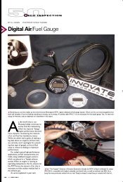
Appendix E: Kit Contents<strong>LC</strong>-1 Kit - P/N: 3769 (as shown)<strong>LC</strong>-1 – P/N: 3744 (3737, 3735, 3773, and 3789 are not included)02 Sensor (P/N: 3737)Program Cable (P/N: 3746)<strong>LC</strong>-1Bung/Plug (P/N: 3735)Terminator Plug (P/N: 3750)2.5mm to 2.5mm Patch Cable (P/N: 3789)Cal Button & LED (P/N: 3773)** Parts with P/N numbers can be purchased separately as replacement parts.- 23 -
Revision History1.0 – 1/23/051.1 – 5/16/051.2 – 5/26/051.3 – 11/03/051.4 – 03/01/061.5 – 03/16/06Initial release.Corrected error in section 6.4Updates to section 3Update Chapter 2Update Chapter 2Added Push Button/ LED, Calibration Schedule, and updated wiring schematic1.6 – 06/08/06Updated Tips and Tricks.1.7 – 02/14/07Update 6 Wire <strong>LC</strong>-1 and new schematic1.8 – 3/16/07Fixed Erroneous data1.9 – 8/23/07Added Kit Contents (Appendix E)- 24 -