arb commercial winch bull bar to suit nissan gu patrol - Offroad obchod
arb commercial winch bull bar to suit nissan gu patrol - Offroad obchod
arb commercial winch bull bar to suit nissan gu patrol - Offroad obchod

You also want an ePaper? Increase the reach of your titles
YUMPU automatically turns print PDFs into web optimized ePapers that Google loves.
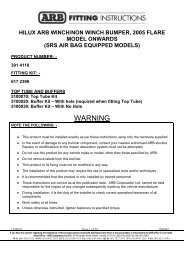
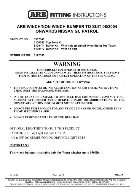
ARB WINCH/NON WINCH BUMPER TO SUIT 08/2004<br />
ONWARDS NISSAN GU PATROL<br />
PRODUCT NO: 3917140<br />
5100090 Top Tube Kit<br />
5100171 Buffer Kit – With hole (required when fitting Top Tube)<br />
5100172 Buffer Kit – With no hole<br />
FITTING KIT NO: 6172355<br />
WARNING<br />
FOR VEHICLES EQUIPPED WITH SRS AIRBAG<br />
WHEN INSTALLED IN ACCORDANCE WITH THESE INSTRUCTIONS, THE FRONT<br />
PROTECTION BAR DOES NOT AFFECT OPERATION OF THE SRS AIRBAG.<br />
TAKE NOTE OF THE FOLLOWING:<br />
• THIS PRODUCT MUST BE INSTALLED EXACTLY AS PER THESE INSTRUCTIONS<br />
USING ONLY THE HARDWARE SUPPLIED.<br />
• IN THE EVENT OF DAMAGE TO ANY BULL BAR COMPONENT, CONTACT YOUR<br />
NEAREST AUTHORISED ARB STOCKIST. REPAIRS OR MODIFICATIONS TO THE<br />
IMPACT ABSORPTION SYSTEM MUST NOT BE ATTEMPTED.<br />
• DO NOT USE THIS PRODUCT FOR ANY VEHICLE MAKE OR MODEL, OTHER THAN<br />
THOSE SPECIFIED BY ARB.<br />
• DO NOT REMOVE LABELS FROM THIS BULL BAR.<br />
OPTIONAL LIGHT SETS TO SUIT THIS PRODUCT:<br />
- ARB 6821201 Fog Light Kit Suit 3163015<br />
- Up <strong>to</strong> IPF 900 SERIES FOG OR DRIVING LIGHT SETS<br />
IMPORTANT<br />
This <strong>winch</strong> bumper is <strong>suit</strong>able only for Warn <strong>winch</strong>es up <strong>to</strong> 9500lb.<br />
26-11-08 Page 1 of 12 3786417<br />
If you have any queries regarding the installation of this product please contact the distribu<strong>to</strong>r from whom it was purchased, or alternatively the ARB office in your state.<br />
Head Office – ARB Corporation Ltd VIC: 42-44 Garden Street, Kilsyth, Vic<strong>to</strong>ria, 3137 Tel: (03) 9761 6622 Fax: (03) 9761 6807<br />
WA:(08) 9244 3553 NSW: (02) 9821 3633 ACT: (02) 6280 7475 SA: (08) 8244 5001 QLD: (07) 3872 3872 NT: (08) 8947 2262 TAS: (03) 6331 4190
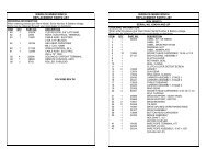
US E. P ART NO. Q TY.<br />
DESCRIPTION<br />
CHASSIS BRACKETS TO<br />
CHASSIS<br />
4581088 2 Chassis rail extension adjuster bolt<br />
6151096 7 Bolt M12 x 1.25 x 40mm<br />
6151095 1 Bolt M12 x 1.25 x 35mm<br />
6151135 2 Nut M12 x 1.25<br />
6151189 2 Nut M12 x 1.75<br />
4581049 2 Washer M12 Flat<br />
4581050 8 Washer M12 Spring<br />
4581007 8 Washer 13mm Heavy duty<br />
4581008 2 Washer 13mm Offset heavy duty<br />
6151087 2 Bolt M10 x 1.25 x 25mm<br />
6151133 2 Nut M10 x 1.25<br />
4581040 4 Washer M10 Flat<br />
4581048 2 Washer M10 Spring<br />
3756395L 1 Chassis bracket LHS<br />
3756395R 1 Chassis bracket RHS<br />
6151135 4 Nut M12 x 1.25<br />
BULL BAR TO CHASSIS 6151095 4 Bolt M12 x 1.25 x 35mm<br />
BRACKETS<br />
4581050 4 Washer Spring M12<br />
4581071 4 Washer shoulder M12<br />
4581070 8 Washer Flat M12<br />
6131321 1 Top Tube assembly<br />
6151255 2 Bolt M12 x 1.75 x 40mm<br />
TOP TUBE TO BAR<br />
4581049 2 Washer M12 Flat<br />
(5100090) 4581050 2 Washer M12 Spring<br />
BUFFERS<br />
6151128 12 Flange nut M6<br />
(5100171 Required if fitting Top 3162469L 1 Buffer LH<br />
Tube) 3162469R 1 Buffer RH<br />
BUFFERS<br />
6151128 12 Flange nut M6<br />
(5100172<br />
3162466L 1 Buffer LH<br />
Required if not fitting Top Tube)<br />
3162466R 1 Buffer RH<br />
6522030 1 Panel <strong>winch</strong> cover<br />
6151256 2 But<strong>to</strong>n head screw M6 x 16mm<br />
WINCH COVER<br />
6151046 2 Washer flat M6<br />
6151128 2 Flange nut M6<br />
6191005 1 Winch cover extrusion<br />
3163015 1 Combination Light Surround Kit<br />
INDICATORS TO BULL BAR 180701 6 Scotch lock<br />
6821152 2 Turn signal/clearance light loom<br />
6821151L 1 TURN SIGNAL/CLEARANCE LIGHT<br />
6821151R 1 TURN SIGNAL/CLEARANCE LIGHT<br />
26-11-08 Page 2 of 12 3786417
US E. P ART NO. QTY. DESCRIPTION<br />
NO. PLATE<br />
AIR DEFLECTOR<br />
6151017 2 Bolt M6 x 16mm<br />
6151046 2 Washer flat M6<br />
6151128 2 Flange nut M6<br />
6781408 1 Double sided tape<br />
6522047 1 Air deflec<strong>to</strong>r front<br />
3314440 1 Air deflec<strong>to</strong>r extension<br />
6151017 10 Bolt M6 x 16mm<br />
6151046 10 Washer flat M6<br />
6151128 7 Flange nut M6<br />
6151315 3 Cage nut M6<br />
3756499 1 Control box bracket<br />
6151020 2 Bolt M8 x 16mm<br />
4581044 2 Washer flat M8<br />
WINCH FITMENT<br />
6151132 2 Flange nut M8<br />
4581040 4 Washer flat 3/8”<br />
6151074 4 Bolt UNC 3/8” x 1 ¾”<br />
BLB 560 3 Winch lead 560mm black<br />
EG50 2 Rubber grommet<br />
180302 10 Cable ties<br />
AERIAL 3162152 2 CB aerial cap<br />
TOOLS REQUIRED.<br />
Basic <strong>to</strong>ol kit: <strong>to</strong>rque wrench, drill, 10mm drill bit, stepped ring spanners.<br />
26-11-08 Page 3 of 12 3786417
BULL BAR PREPARATION<br />
Washer 12mm<br />
Bolt M12x35m<br />
Shoulder Washer<br />
Nut M12<br />
Spring Washer<br />
Washer 12mm<br />
Bull Bar Upright (RHS)<br />
Chassis Bracket (RHS)<br />
1. Assemble the two chassis brackets <strong>to</strong><br />
the <strong>bull</strong> <strong>bar</strong> using two per side, M12 x<br />
35mm bolts, heavy duty D washers,<br />
shoulder washers, heavy duty D<br />
washers, spring washers and nuts.<br />
2. Position the impact absorbers centrally<br />
on the upright slots. These slots were<br />
provided <strong>to</strong> accommodate chassis height<br />
variations.<br />
3. Tighten the bolts firmly; though do not<br />
fully tighten as they may be adjusted at<br />
step 31.<br />
Chassis Rail Extension<br />
Adjuster Bolt<br />
(Wind Fully In)<br />
4. Rest the <strong>bar</strong> face down on two stands so<br />
assembly can be carried out.<br />
5. Assemble a 12mm nut <strong>to</strong> each chassis<br />
rail extension adjuster bolt and fully<br />
screw in<strong>to</strong> <strong>bull</strong> <strong>bar</strong>.<br />
6. Do not tighten, as this will be adjusted<br />
later.<br />
Bull Bar<br />
1. Fit the buffers. Buffer studs fit through<br />
the slots in the wings and the pan.<br />
Fasten using M6 flange nuts.<br />
Note: This applies <strong>to</strong> both blank buffers<br />
those with the hole for optional frame.<br />
and for<br />
CAUTION: DO NOT OVER TIGHTEN THE M6<br />
NUTS AS YOU RISK PULLING THE STUDS<br />
OUT OF THE BUFFERS.<br />
26-11-08 Page 4 of 12 3786417
WINCH FITMENT<br />
7. For ease of access the <strong>winch</strong> ge<strong>arb</strong>ox<br />
handle needs <strong>to</strong> be rotated. To do this,<br />
first undo all the cap screws and<br />
carefully lift the ge<strong>arb</strong>ox clear of the<br />
<strong>winch</strong> body so as not <strong>to</strong> damage the<br />
gasket. (Do not lift the ge<strong>arb</strong>ox more<br />
than a couple of millimetres) Rotate<br />
the ge<strong>arb</strong>ox 144° anti clockwise. Re-fit<br />
the caps-crews.<br />
8. Remove the cover from the control box.<br />
9. The three main power cables that go<br />
from <strong>winch</strong> <strong>to</strong> control box must be<br />
changed over using longer cables from<br />
bolt kit. Make sure that you identify the<br />
colour codes on the new cables before<br />
re-fitting the control box cover.<br />
NOTE: This must be done for whatever<br />
<strong>winch</strong> is <strong>to</strong> be fitted <strong>to</strong> the <strong>bull</strong> <strong>bar</strong>.<br />
10. If fitting the XP 9.5 <strong>winch</strong>, remove the<br />
cover from the control box. Remove the<br />
two cap screws, nuts and spacer<br />
washers that hold the four solenoids in<br />
place.<br />
11. Remove the four solenoids from the<br />
base of the control box using the copper<br />
bus <strong>bar</strong> as an aid and hold <strong>to</strong> one side.<br />
26-11-08 Page 5 of 12 3786417
26-11-08 Page 6 of 12 3786417
12. Remove the two bolts in the base of the<br />
control box and reposition them in<strong>to</strong> the<br />
more centralised holes.<br />
13. Replace the 4 solenoids, making sure<br />
they line up with the holes in the base.<br />
14. Replace the 2 cap screws, washers and<br />
nuts removed in step 13 above in<strong>to</strong><br />
original holes.<br />
15. Replace the black cover and refit the<br />
three cover screws. (DO NOT OVER<br />
TIGHTEN)<br />
16. Bolt the control box bracket <strong>to</strong> the control<br />
box.<br />
17. Fit the two grommets in<strong>to</strong> the round<br />
holes then thread the cable through.<br />
18. Mount the control box bracket on<strong>to</strong> the<br />
<strong>to</strong>p pan, using M8 bolts, flat washers and<br />
flanged nuts. Use the cable ties <strong>to</strong><br />
ensure the <strong>winch</strong> cables are secure,<br />
clear of moving parts and sharp edges<br />
and tie them <strong>to</strong>gether.<br />
26-11-08 Page 7 of 12 3786417
19. Place <strong>winch</strong> on a stand with mounting<br />
holes facing upwards and lower <strong>bull</strong> <strong>bar</strong><br />
on<strong>to</strong> <strong>winch</strong>. Align all four holes and<br />
secure using 1 ½” x 3/8” bolts on <strong>to</strong>p<br />
holes and 1 ¾” x 3/8” bolts on lower<br />
holes, plus 3/8” spring and flat washers.<br />
20. When all bolts are fitted and finger tight,<br />
centralize bolts in holes and tighten <strong>to</strong>p<br />
holes only, using a stepped ring spanner.<br />
21. Remove lower bolts.<br />
22. Fit roller fairlead in<strong>to</strong> cu<strong>to</strong>ut and refit bolts<br />
and tighten firmly.<br />
23. Connect the <strong>winch</strong> control box cables <strong>to</strong><br />
the <strong>winch</strong>. Refer <strong>to</strong> Warn installation<br />
instruction manual when wiring up <strong>winch</strong>.<br />
Ensure that all cables are installed well<br />
clear of all sharp or moving parts, by<br />
using cables ties from bolt kit.<br />
BULL BAR FITMENT<br />
FUNCTION<br />
INDICATOR<br />
HARNESS<br />
VEHICLE COMBINATION LAMP<br />
RIGHT<br />
LEFT<br />
TURN LAMP GREEN GREEN / RED GREEN / YELLOW<br />
EARTH BLACK BLACK BLACK<br />
PARK LAMP RED BLUE/BLACK BLUE/BLACK<br />
24. Remove the splash <strong>gu</strong>ards attached <strong>to</strong><br />
the bumper and remove the bumper and<br />
grille from vehicle.<br />
25. Remove the vehicle’s head lamps and<br />
wire the indica<strong>to</strong>r looms provided in the<br />
kit <strong>to</strong> the vehicle’s indica<strong>to</strong>r loom using<br />
scotch locks. Leave these new looms<br />
hanging freely for easy access when the<br />
<strong>bar</strong> is fitted.<br />
26. Re-attach the vehicle’s head lamps and<br />
grille.<br />
26-11-08 Page 8 of 12 3786417
26-11-08 Page 9 of 12 3786417
27. Before fitting the <strong>bull</strong> <strong>bar</strong>, using black<br />
paint, paint the section between <strong>bull</strong> <strong>bar</strong><br />
wing and the bot<strong>to</strong>m of the headlight.<br />
28. Position the <strong>bull</strong> <strong>bar</strong> on <strong>to</strong>p of the<br />
chassis rails and bolt in<strong>to</strong> place using the<br />
M12 x 40mm bolts, heavy-duty washers<br />
and spring washers.(Do not tighten)<br />
NOTE: Due <strong>to</strong> variations in the vehicle<br />
chassis rails it may be necessary <strong>to</strong> place a<br />
packer between the chassis rail <strong>to</strong>p and the<br />
<strong>bull</strong> <strong>bar</strong>. A heavy-duty washer is supplied<br />
for this purpose.<br />
29. Fit M12 x 40mm bolts, spring washers<br />
and heavy-duty flat offset washers<br />
through <strong>bull</strong> <strong>bar</strong> side mounting holes in<strong>to</strong><br />
original bumper <strong>bar</strong> captive nut mounting<br />
holes. (Do not Tighten)<br />
26-11-08 Page 10 of 12 3786417
30. Fit M12 x 40mm bolt (passenger’s side)<br />
& M12 x 35mm bolt (driver’s side), ½”<br />
flat washers, heavy duty flat washers,<br />
spring washers and 12mm nuts <strong>to</strong> lower<br />
<strong>bull</strong> <strong>bar</strong> mounting holes and vehicle tie<br />
down plates. (Do not Tighten)<br />
NOTE: Insert bolt from outside of lower<br />
mount holes so heavy-duty washer covers<br />
large hole on tie down plate.<br />
31. Adjust the <strong>bull</strong> <strong>bar</strong> <strong>to</strong> achieve a uniform<br />
gap <strong>to</strong> the grill and mud<strong>gu</strong>ards. If<br />
additional height adjustment is required,<br />
the M12 bolts fitted at step 5 may be<br />
loosened for additional adjustment.<br />
32. Tighten all the fitted bolts, including those<br />
fitted at step 5, <strong>to</strong> a <strong>to</strong>rque of 77Nm or 80<br />
ft-lb.<br />
33. Once the <strong>bar</strong> is secured, using the 10mm<br />
holes in chassis bracket as template, drill<br />
10mm hole through side of chassis and<br />
secure using M10 x 40mm bolt, flat<br />
washers, spring washer and nut.<br />
34. Wind each impact absorber adjuster bolt<br />
out until it is firm against the chassis rail<br />
extensions and tighten the lock nut.<br />
26-11-08 Page 11 of 12 3786417
IF FITTING TOP TUBE<br />
35. Push the tube through the holes in the<br />
<strong>to</strong>p of the buffer and fix using the M12 X<br />
40mm bolts washers and spring<br />
washers.<br />
36. Assemble and install combination light<br />
surrounds (p/n 3163015) as per instructions<br />
no. 3786421 supplied with surround kit. Note:<br />
Optional fog lamps can be installed at this<br />
point as per fitting instruction no. 3783315<br />
supplied with fog lamp kit no. 6821201.<br />
Wire the combination lamp <strong>to</strong> the vehicles<br />
indica<strong>to</strong>r and clearance lamps.<br />
Caution: Cable tie all cables <strong>to</strong>gether and keep<br />
all cables clear of sharp edges and moving<br />
parts.<br />
26-11-08 Page 12 of 12 3786417
37. Fit three M6 cage nuts <strong>to</strong> the upper<br />
deflec<strong>to</strong>r panel as shown on the left.<br />
38. For non-4.8 litre petrol engine vehicles,<br />
assemble the second deflec<strong>to</strong>r panel<br />
using M6x16mm bolts, washers and<br />
flange nuts as shown on the left.<br />
39. 4.8 litre petrol engine vehicles only<br />
require the upper panel <strong>to</strong> be fitted <strong>to</strong> the<br />
vehicle.<br />
40. Fit the air deflec<strong>to</strong>r / deflec<strong>to</strong>rs using M6<br />
nuts and bolts.<br />
41. Fit three M6x16 bolts and washers<br />
through the front of the upper deflec<strong>to</strong>r<br />
in<strong>to</strong> the cage nuts previously installed.<br />
42. Fit two M6x16 bolts through the two slots<br />
on each side of the deflec<strong>to</strong>r. Use M6<br />
washers and flange nuts <strong>to</strong> fasten the<br />
deflec<strong>to</strong>r <strong>to</strong> the mating impact absorbers.<br />
These slots are accessible through the<br />
cut-outs in the deflec<strong>to</strong>r.<br />
26-11-08 Page 13 of 12 3786417
43. If no <strong>winch</strong> is fitted <strong>to</strong> the <strong>bar</strong>, wrap<br />
rubber extrusion around <strong>winch</strong> cover.<br />
44. Place washers over the <strong>winch</strong> cover<br />
fixing holes located on the <strong>to</strong>p middle<br />
face of the <strong>winch</strong> <strong>bar</strong>.<br />
45. Place the <strong>winch</strong> cover on <strong>to</strong>p of the <strong>bar</strong><br />
inline with the mount holes. Bolt <strong>to</strong>gether<br />
using the M6 but<strong>to</strong>n head stainless steel<br />
screws and M6 nuts.<br />
46. Place the double-sided tape along the<br />
<strong>to</strong>p edge of the licence plate. Fit number<br />
plate <strong>to</strong> <strong>bar</strong> using M6x16 bolts, washers<br />
and flange nuts. The two pho<strong>to</strong>s display<br />
the number plate positions for <strong>winch</strong> and<br />
non-<strong>winch</strong> <strong>bar</strong>s.<br />
26-11-08 Page 14 of 12 3786417
47. There are two diameter 16 holes located<br />
on the <strong>to</strong>p face of the <strong>bar</strong>. If no CB<br />
aerials are fitted the holes can be<br />
covered with the plastic plugs provided in<br />
the fitting kit.<br />
48. When finished make sure all bolts are<br />
tightened and that all wiring is clear of<br />
hot, sharp and moving parts.<br />
26-11-08 Page 15 of 12 3786417