ARB 78/79 Series SIDE STEP/RAILS - Offroad obchod
ARB 78/79 Series SIDE STEP/RAILS - Offroad obchod
ARB 78/79 Series SIDE STEP/RAILS - Offroad obchod

Create successful ePaper yourself
Turn your PDF publications into a flip-book with our unique Google optimized e-Paper software.
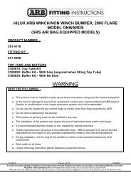
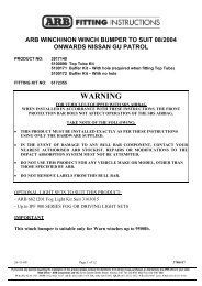
<strong>ARB</strong> WINCH/NONWINCH SAHARA BAR TO SUIT TOYOTA HJ100 6 CYL.PRODUCT No. 39131505100050 Top Tube Kit5100173 Buffer Kit – With hole (required when fitting Top Tube)5100174 Buffer Kit – With no holeFITTING KIT No: 6172352WARNINGFOR VEHICLES EQUIPPED WITH SRS AIRBAGWHEN INSTALLED IN ACCORDANCE WITH THESE INSTRUCTIONS, THEFRONTPROTECTION BAR DOES NOT AFFECT OPERATION OF THE SRS AIRBAG.TAKE NOTE OF THE FOLLOWING:• THIS PRODUCT MUST BE INSTALLED EXACTLY AS PER THESEINSTRUCTIONS USING ONLY THE HARDWARE SUPPLIED.• DO NOT USE THIS PRODUCT FOR ANY VEHICLE MAKE OR MODEL, OTHERTHAN THOSE SPECIFIED BY <strong>ARB</strong>.• DO NOT REMOVE LABELS FROM THIS BULL BAR.• THIS PRODUCT OR ITS FIXING MUST NOT BE MODIFIED IN ANY WAY.OPTIONAL LIGHT SETS TO SUIT THIS PRODUCT:- <strong>ARB</strong> 6821201 Fog Light Kit Suit 3163015- Up to IPF 900 SERIES FOG OR DRIVING LIGHT SETSTools Required10mm, 18mm, 19mm, 21mm Spanners and Sockets. Phillips head screwdriver, Cordless Drill with phillipshead tip (Optional).26/11/08 Page 1 of 11 3<strong>78</strong>6414If you have any queries regarding the installation of this product please contact the distributor from whom it was purchased, or alternatively the <strong>ARB</strong> office in your state.Head Office – <strong>ARB</strong> corporation Ltd VIC: 42-44 Garden Street, Kilsyth, Victoria, 3137 Tel: (03) 9761 6622 Fax: (03) 9761 6807WA:(08) 9244 3553 NSW: (02) 9821 3633 ACT: (02) 6280 7475 SA: (08) 8244 5001 QLD: (07) 3872 3872 NT: (08) 8947 2262 TAS: (03) 6331 4190
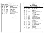
USE PART No QTY DESCRIPTIONTOP & IN<strong>SIDE</strong> OF MOUNT 3751824 1 MOUNT ASSEMBLYASSEMBLY TO CHASSIS 6151094 4 M12 X 30mm BOLT4581049 4 M12 FLAT WASHER4581050 4 M12 SPRING WASHERUNDER<strong>SIDE</strong> OF MOUNT 5846222 2 PACKERASSEMBLY TO CHASSIS 6151097 4 M12 X 50mm BOLT4581049 4 M12 FLAT WASHER4581050 4 M12 SPRING WASHEROUT<strong>SIDE</strong> OF MOUNT 6151087 4 M10 X 25mm BOLTASSEMBLY TO CHASSIS 4581048 4 M10 SPRING WASHER4581041 4 M10 FLAT WASHERRUBBER EXTRUSION FITTMENT 6821116 14 SQUARE PLASTIC PLUG6151176 14 SCREW SELF TAPPING 12mm 8G6191002 2 EXTRUSION3193616 2 MOUNT STRIPSWINCH BUMPER TO MOUNT ASS 6151255 6 BOLT M12 X 40mm4581050 6 WASHER SPRING M124581007 6 WASHER FLAT M12 LARGEWINCH 4581041 4 M10 FLAT WASHERBUFFER FITTMENT 6151128 12 NUT FLANGE M6(5100173 Required if fitting 3162153 1 BUFFER LHSTop Tube) 3162154 1 BUFFER RHSBUFFER FITTMENT 6151128 12 NUT FLANGE M6(5100174 Required if not fitting 3162171L 1 BUFFER LHSTop Tube) 3162171R 1 BUFFER RHSBUFFER LOWER FITTMENT 6151128 5 NUT FLANGE M63162155 1 BUFFER LOWERTOP TUBE FITTMENT 6151255 2 BOLT M12 X 40mm(5100050) 4581049 2 WASHER FLAT M124581050 2 WASHER SPRING M126131150 1 TOP TUBE10/12/2004 Page 2 of 11 3<strong>78</strong>6414
CONTROL BOX FITTMENT 3751809 1 CONTROL BOX BRACKET6151017 2 BOLT M6 X 16MM6151128 4 NUT FLANGE M6ROLLER FAIRLEAD FITTMENT 6151255 2 BOLT M12 X 40mm4581050 2 WASHER SPRING M124581049 4 WASHER FLAT M126151189 2 NUT M12WINCH COVER FITTMENT 6151128 2 NUT FLANGE M66151256 2 SCREW M6 S/STEEL BUTTON HEAD6191001 1 WINCH COVER EXTRUSION6521031 1 WINCH COVER6151046 2 WASHER M6NUMBER PLATE FITTMENT 6151017 2 BOLT M6 X 16mm6151128 2 NUT FLANGE M66<strong>78</strong>1408 1 TAPE DOUBLE <strong>SIDE</strong>DLIGHT HOUSING 3163015 1 KIT SURROUND FOR FOG AND INDICATOR LIGHTS6821151L 1 TURN SIGNAL / CLEARANCE LIGHT6821151R 1 TURN SIGNAL / CLEARANCE LIGHTCB & HEADLIGHT WASHER 3162152 2 PLASTIC PLUG DIA 163162159 2 PLASTIC PLUG DIA 22WIRING 6821152 2 TURN SIGNAL / CLEARANCE LIGHT LOOM180701 6 SCOTCH LOCK180302 10 CABLE TIE10/12/2004 Page 3 of 11 3<strong>78</strong>6414
ASSEMBLY SEQUENCE FOR WINCH BAR.1. 1. Disassemble the mount assy. from the winchbumper by removing the transit bolts.2. Remove the bumper bar and grill.2. 1. Slide the mount assy. over thechassis rails.2. Push the entire mount as farback as possible.3. Secure the mount assy withthe hardware shown28/04/08 Page 4 of 11 3<strong>78</strong>6414
ASSEMBLY SEQUENCE FOR WINCH BAR.3. 1. Using vice grips, multi grips or pliers bend back thebumper mounting arm approximately 30 – 40degree’s To clear winch bumper when assembled.4. (If fitting with winch)To place the clutch handle in a convenient location thewinch gearbox must be rotated two hole spacings.1. Place the winch on its end and remove all gearboxbolts.2. Gently raise the motor just enough to rotate it.3. Do not completely remove the motor and avoiddamaging the gasket.4. Refit and tighten all bolts.Note: Take care not to lift the assembly more than acouple of millimeters while rotating to the desiredposition to avoid unmeshing the gears.5. (If fitting with winch.)1. Place the winch on the mount assembly. Cablespools from the top.Bolt from underneath using bolts supplied with winch.Refer to Warn installation instructions for correctprocedure.28/04/08 Page 5 of 11 3<strong>78</strong>6414
ASSEMBLY SEQUENCE FOR WINCH BAR.6. 1. The rubber extrusion contains a support section toassist in the moulding. Remove this section bytearing at one end. Discard this section.2. Insert the square plastic plugs into the square holeson the top face of the wing.7. 1. Insert the mount strips inside the channel section ofthe rubber extrusion. Make sure the flap section ison the outer side. Allow generous even amounts ofexcess at either end of the strip so that it can betrimmed later.8. 1. Using a philips head screw driver or cordless drillwith a philips head tip fix the extrusions to the topof the wings using the self taper screws.28/04/08 Page 6 of 11 3<strong>78</strong>6414
ASSEMBLY SEQUENCE FOR WINCH BAR.9. 1. Using a sharp knife cut the excess rubber in linewith the inside end of the wing. Only cut the insideexcess, the other end will be cut when the winchbumper is fitted.10. 1. With the aid of another person place the bar on themount assy.11. 2. Insert the M12 X 40mm bolts with the large platewashers and spring washers to finger tight.3. Using another person position the bar to line up therubber extrusion with the profile of the vehicle.Hold the wing of the bar so an even gap ofapproximately 15mm is achieved. Tighten bolts.4. Repeat on other side.28/04/08 Page 7 of 11 3<strong>78</strong>6414
ASSEMBLY SEQUENCE FOR WINCH BAR.12. 1. Position the lower buffer on the winch bumper andassemble using the M6 flange nuts.13. 1. Fit the buffers. Buffer studs fit through the slotsin the wings and the pan. Fasten using M6flange nuts.Note: This applies to both blank buffers and for thosewith the hole for optional frame.CAUTION: DO NOT OVER TIGHTEN THE M6NUTS AS YOU RISK PULLING THE STUDS OUTOF THE BUFFERS.14. IF FITTING THE TOP TUBE1. Push the chrome tube through the holes in the topof the buffer and fix using the M12 X 40mm boltswashers and spring washers.28/04/08 Page 8 of 11 3<strong>78</strong>6414
ASSEMBLY SEQUENCE FOR WINCH BAR.15. (If fitting with winch)1. Assemble the control box bracket to the control boxusing M6 flange nuts.2. Mount the control box to the bar using M6 X 16bolts and M6 flange nuts.16. (If fitting with winch)1. Bolt the roller fair lead to the winch bumper usingthe M12 X 40mm bolts, washers, spring washersand nuts.17. (If fitting with winch)1. Feed the winch cable through the roller fair lead.Mount the hook to the end of the cable.28/04/08 Page 9 of 11 3<strong>78</strong>6414
ASSEMBLY SEQUENCE FOR WINCH BAR.18. (If not fitting winch)1. Wrap rubber extrusion around winch cover.2. Place washers over the winch cover fixing holeslocated on the top middle face of the winch bumper.3. Place the winch cover on top of the winch bumperinline with the mount holes.4. Bolt together using the M6 button head stainless steelscrews and M6 nuts.19.Fitting with winchFitting without winch(If fitting with winch.)1. Peel off one side of the double sided tape and adhereto the top rear side of the number plate. Note: Cleanthe adhering surfaces before applying tape with analcohol solvent.2. Peel off the other side of the tape and bolt to thewinch bumper with the M6 X 16mm bolts and M6flange nuts through the lower holes of the numberplate.3. Press firmly to the top of the number plate so the tapecan properly adhere.(If not fitting with winch.)1. Bolt the number plate through the top holes using M6X 16mm bolts and M6 flange nuts.2. If desired the double sided tape can be used down thesides of the number plate.20. Assemble and install combination light surrounds (p/n3163015) as per instructions no. 3<strong>78</strong>6421 supplied withsurround kit. Note: Optional fog lamps can be installed atthis point as per fitting instruction no. 3<strong>78</strong>3315 suppliedwith fog lamp kit no. 6821201.Wire the combination lamp to the vehicles indicator andclearance lamps.Caution: Cable tie all cables together and keep all cablesclear of sharp edges and moving parts.28/04/08 Page 10 of 11 3<strong>78</strong>6414
ASSEMBLY SEQUENCE FOR WINCH BAR.21. 1. If fitted, headlight washers can be mounted throughthe Dia 22 holes on the top face of the wing.Assemble using the existing mount clips. Two plugsare provided to cover the holes if there are noheadlight washers on the vehicle.Place the <strong>ARB</strong> logo on the front face of the bar in theindentation.Trim rubber extrusion at end of wing using a sharpknife. Cut on an angle to match the angle of wing andwheel arch.22.(If fitting with winch)Connect the winch control box cables to the winch motor. Refer to the Warn handbook for additionalinformation. Connect the long winch + & - cables to the vehicle after the bar is installed. Refer to the Warnwinch manual for vehicle wiring instructions.Note: If fitting 10,000lb winch, cable kit 6171397 is required. Use the longer leads to replace ones oncontrol box.Ensure that these cables are installed well clear of sharp, hot or moving objects. Secure the winch cables tothe vehicle and winch bumper with the supplied cable ties.23.Wire the clearance / turn signal lights to the vehicle wiring.24.Trim the extrusion between the winch bumper and vehicle using a sharp knife flush with the end of the wing.28/04/08 Page 11 of 11 3<strong>78</strong>6414