NISSAN GU PATROL WINCH BULL BAR - Offroad obchod
NISSAN GU PATROL WINCH BULL BAR - Offroad obchod
NISSAN GU PATROL WINCH BULL BAR - Offroad obchod

You also want an ePaper? Increase the reach of your titles
YUMPU automatically turns print PDFs into web optimized ePapers that Google loves.
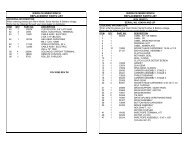
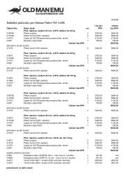
6522649 1 PANEL STONE <strong>GU</strong>ARD UPPER HILUX 056522650 1 PANEL STONE <strong>GU</strong>ARD LOWER HILUX 056151303 4 CAGE NUT, M8 (3mm PLATE)CENTRE STONE DEFLECTORS 6151301 4 CAGE NUT, M8 (4mm PLATE)4581045 8 WASHER, FLAT, M8 (BLACK)4581047 8 WASHER, SPRING, M8 (BLACK)6151234 8 BOLT, M8 x 1.25 x 25 LONG (BLACK)6522651R 1 PANEL, WING (RH), HILUX 056522651L 1 PANEL, WING (LH), HILUX 056151315 10 CAGE NUT, M6 (1.6mm PLATE)4581082 10 WASHER, FLAT, M6 (BLACK, 20 OD)WING STONE DEFLECTORS 4581287 10 WASHER, SPRING, M6 (BLACK)6151213 10 BOLT, M6 x 1.0 x 20 (BLACK)6151094 2 BOLT M12 x 1.25 x 30 LONG4581049 2 WASHER, FLAT M124581050 2 WASHER, SPRING M12180302 4 CABLE TIESTOP TUBE TO <strong>BULL</strong> <strong>BAR</strong>(5100070)613 1371 1 TOP TUBE ASSEMBLY6151255 2 BOLT M12 x 1.75 x 40 mm LONG4581049 2 WASHER M12 FLAT4581050 2 WASHER M12 SPRING6522661 1 PANEL <strong>WINCH</strong> COVER6151256 2 BUTTON HEAD SCREW M6 x 16 mm<strong>WINCH</strong> COVER PANEL 6151046 2 WASHER FLAT M66151128619100521AERIAL PLUGS 3162152 2 CB AERIAL CAPWASHER FLAT M6<strong>WINCH</strong> COVER EXTRUSIONOPTIONAL LIGHT SETS TO SUIT THIS PRODUCT:ARB 6821201 Fog light kit to suit 3163015Up to IPF 900 series fog or driving light setsTools required: -10mm drill bit and drill, 5mm drill bit and drill, Satin black spray can, scissors, ruler, basicspanner & screw driver set, stepped ring spanner to suit 3/8” bolt.17/09/07 Page 4 of 20 3786942
ASSEMBLY SEQUENCE FOR <strong>BULL</strong> <strong>BAR</strong> INSTALLATION.1. Remove existing bumper and grill fromthe vehicle.Once these are removed:- Remove plastic fittings attached to thefender and discard- Remove the light bracket fitting anddiscard, this is done by first removingthe light and then unscrewing thebracket from the rear of the light fitting.- Remove the bumper braces anddiscard.- Remove the chassis cross-brace anddiscard.2. Remove the vehicles headlights.3. Carefully read the wiring diagramsupplied at the end of theseinstructions.4. Take the relay loom (6821198) from thekit and position in the engine bay sothat all wires will reach the appropriateconnections.5. Starting with the passenger side, usescotch locks to connect the red wirefrom the indicator loom (6821152) tothe green wire from the vehicles frontpark lamp.6. Connect the Yellow / Black wire fromthe relay loom to the Green / Black wirefrom the vehicles left indicator.17/09/07 Page 5 of 20 3786942
7. Connect the Yellow and Black wiresfrom the relay loom to the Green andBlack wires from the indicator loom.8. Let the indicator loom hang freely forconnecting to the bull bar indicatorslater on.9. Do the same for the drivers side usingthe wiring diagram supplied as areference for the correct wire colors.10. Find a suitable place and mount therelay.NOTE: Always mount the relay upright tohelp prevent water ingress.11. Run the main black wire to a suitableearth.12. Connect the main power wire (red) tothe positive terminal of the battery.(Main battery if a dual battery system isinstalled)17/09/07 Page 6 of 20 3786942
22. Remove the cover from the control box.23. Replace the three main power cablesthat go from winch to control box. Makesure that you identify the colour codeson the new cables before closingcontrol box cover.24. This must be done for whatever winchis to be fitted to the bull bar.25. If fitting the XP 9.5 winch, remove thecover from the control box, otherwiseproceed to step 33.26. Remove the two cap screws, nuts andspacer washers that hold the foursolenoids in place.27. Remove the four solenoids from thebase of the control box using thecopper bus bar as an aid and hold toone side.17/09/07 Page 10 of 20 3786942
28. Remove the two bolts in the base of thecontrol box and reposition them into themore centralized holes.BeforeAfter29. Place the 4 solenoids over the 2 metalstands that are facing upwards. Makesure they line up with the holes in thebase.30. Replace the 2 cap screws, washersand nuts removed earlier31. Replace the black cover and refit thethree cover screws. (DO NOT OVERTIGHTEN)32. Bolt the control box bracket to thecontrol box.33. Fit the two grommets into the roundholes in the top of the bull bar thenthread the cables through.34. Mount the control box bracket onto thetop pan, using M8 bolts, flat washersand flanged nuts. Use the cable ties toensure the winch cables are secure,clear of moving parts and sharp edgesand tie them together.17/09/07 Page 11 of 20 3786942
35. Place winch on a stand with mountingholes facing upwards and lower bull baronto winch. Align all four holes, using theoriginal 3/8” bolts that came with thewinch in the top two holes and the longer1 ¾” x 3/8” bolts, supplied in the kit, inthe lower two holes plus 3/8” spring andflat washers with each bolt.36. When all bolts are fitted and finger tight,tighten top holes only, using a steppedring spanner and remove lower bolts.37. Drill two new 13mm holes in the rollerfairlead provided in the kit, as shown onthe adjacent picture.38. Fit roller fairlead into cutout and refitbolts and tighten firmly.NOTE. For ease of tightening lower bolts, use astepped ring spanner.17/09/07 Page 12 of 20 3786942
39. Connect the winch control box cables tothe winch. Refer to Warn installationinstruction manual when wiring up winch.40. Ensure that all cables are installed wellclear of all sharp or moving parts, byusing cables ties from bolt kit.41. Cable tie main cables that go to batteryin between underside of bar and brace.Refer to photo to see where to cable tie to bullbar.M8 CageNuts42. Fit four M8 cage nuts to the impactabsorber. (Cage nuts to suite 4mm plate)Caged portion to top of bull bar.43. Fit the impact absorber to the bull-barusing the M10 x 30 bolts, M10 over-sizedwashers and M10 spring washers. Donot fully tighten these bolts as they willbe tightened on the vehicle.44. Position the bar on the vehicle andfasten it to the chassis studs using theM10 washers, spring washers and nutsprovided. Once satisfied that the bar iscentrally positioned on the vehicleproperly tighten the M10 nuts.17/09/07 Page 13 of 20 3786942
45. Adjust the bull bar position up/down andin/out to achieve uniform gaps betweenthe bar and the fenders on each side ofthe vehicle. The nominal clearancebetween the bull-bar and the fenders is20mm. Firmly tighten the bolts fitted atstep 44.The grill may be loosely positioned, if required,to check fitment of the bull-bar.46. Once satisfied with the position of thebull-bar, using a 10mm drill, drill throughthe 10mm holes in the impact absorber,2 holes per side, and secure using theM10 x 30 bolts, two flat washers per bolt,spring washers and hex nuts.47. Position the wing trims to fit uniformlyaround the vehicles headlamps(attached to the bull-bar at step 20) andtighten the M6 nuts.17/09/07 Page 14 of 20 3786942
48. Fasten the lower grill bracket to thevehicle head lights, as shown, usingM8 x 25 black bolts, flat washers,spring washers and flange nuts.49. Reassemble the vehicle’s grill removedat step 1; make sure the 2 lower grilltabs are pushed into the clips in thelower grill bracket. Bend lower grillbracket tab upwards slightly.50. Fasten the chassis-stiffening bracket tothe chassis and the impact absorberas shown. Fasteners required include:six M10 x 35 bolts, twelve M10 flatwashers, six M10 spring washers, sixhex nuts, two M8 x 25 bolts, two flatM8 washers and two M8 springwashers.Leave bolt hole clear for step 57.51. Fit the centre stone guards as shownusing M8 x 25 black bolts, black M8flat washers and black M8 springwashers.Use the original bolts in the lower two holes.17/09/07 Page 15 of 20 3786942
52. Push the tube through the holes in thetop of the buffer and fix using the M12X 40mm bolts washers and springwashers.FOR <strong>WINCH</strong> BUMPERS, SKIP THIS STEP.53. Fit the M6 cage nuts to the wing stoneguards – 5 cage nuts to each side(10 off in total).Make sure the plastic wheel liner on the LHside of the vehicle has been disconnectedfrom the washer bottle before fitting the wingstone guards.54. Fit the wing stone guards to the bar /vehicle using M6 x 20 black bolts, M6black washers, M6 black spring washers,M12 x 30 bolts, M12 washers, and M12spring washers.17/09/07 Page 16 of 20 3786942
55. Cable tie the plastic wheel liner on theLH side of the vehicle to the two holesprovided in the wing and the wing stoneguard, as shown in the adjacent photo.56. Cut the lower part of the plastic wheelliner that hangs below the wing stoneguard with a pair of scissors or sharpknife.For Vehicles ManufacturedMay 2006 and Onward: - The above two stepswill need to be repeated on the Right Hand Sideof the Vehicle also.17/09/07 Page 17 of 20 3786942
57. If fitting optional driving lights to vehicledo so at this stage. Guide ratchetspanner between the upper and lowerpans, as shown, to tighten the lights tothe bar.58. Fit the plastic plugs into the squareholes in the lower pan. Fit the numberplate to the bull bar using the blackself-tapping screws. The two photosdisplay the number plate positions forboth winch and non-winch bars.Provision for a high-lift jack is provided onboth sides of the bar.17/09/07 Page 18 of 20 3786942
59. If no winch is fitted to the bar, wrap therubber extrusion around winch cover.Place washers over the winch coverfixing holes located on the top middleface of the winch bar. Place the winchcover on top of the bar inline with themount holes. Bolt together using theM6 button head stainless steel screwsand M6 nuts.60. There are two diameter 16 holeslocated on the top face of the bar. If noCB aerials are fitted the holes can becovered with the plastic plugs providedin the fitting kit.61. When finished make sure all bolts aretightened and that all wiring is clear ofhot, sharp and moving parts.17/09/07 Page 19 of 20 3786942
IndicatorLoom PartNo 6821152Relay LoomPart No6821198IndicatorLoom PartNo 682115217/09/07 Page 20 of 20 3786942