

Technical Manual - Rice Lake Weighing Systems
Technical Manual - Rice Lake Weighing Systems
Technical Manual - Rice Lake Weighing Systems

You also want an ePaper? Increase the reach of your titles
YUMPU automatically turns print PDFs into web optimized ePapers that Google loves.
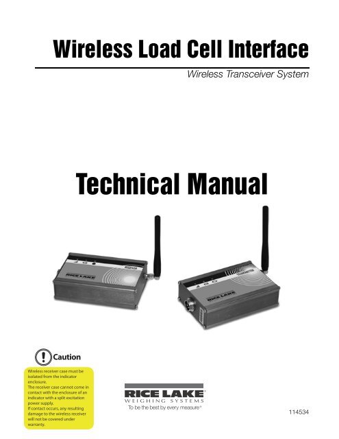
Wireless Load Cell Interface<br />
Wireless Transceiver System<br />
<strong>Technical</strong> <strong>Manual</strong><br />
Caution<br />
Wireless receiver case must be<br />
isolated from the indicator<br />
enclosure.<br />
The receiver case cannot come in<br />
contact with the enclosure of an<br />
indicator with a split excitation<br />
power supply.<br />
If contact occurs, any resulting<br />
damage to the wireless receiver<br />
will not be covered under<br />
warranty.<br />
To be the best by every measure<br />
114534
Contents<br />
About This <strong>Manual</strong> ................................................................................................................................... 1<br />
1.0 Overview ...................................................................................................................................... 1<br />
2.0 Enclosures ................................................................................................................................... 2<br />
2.1 Anodized Enclosure . . . . . . . . . . . . . . . . . . . . . . . . . . . . . . . . . . . . . . . . . . . . . . . . . . . . . . . . . . . . . . 2<br />
3.0 Transceiver Connections ............................................................................................................. 3<br />
3.1 Anodized Enclosure . . . . . . . . . . . . . . . . . . . . . . . . . . . . . . . . . . . . . . . . . . . . . . . . . . . . . . . . . . . . . . 3<br />
3.2 Stainless Steel Nema 4 Enclosure . . . . . . . . . . . . . . . . . . . . . . . . . . . . . . . . . . . . . . . . . . . . . . . . . . . 3<br />
4.0 Load Cell Transmitter Installation ............................................................................................... 4<br />
4.1 Anodized Enclosure . . . . . . . . . . . . . . . . . . . . . . . . . . . . . . . . . . . . . . . . . . . . . . . . . . . . . . . . . . . . . . 4<br />
4.2 Stainless Enclosure . . . . . . . . . . . . . . . . . . . . . . . . . . . . . . . . . . . . . . . . . . . . . . . . . . . . . . . . . . . . . . 4<br />
5.0 Indicator Receiver Installation.................................................................................................... 5<br />
5.1 Anodized Enclosure . . . . . . . . . . . . . . . . . . . . . . . . . . . . . . . . . . . . . . . . . . . . . . . . . . . . . . . . . . . . . . 5<br />
5.2 Stainless Steel Enclosure . . . . . . . . . . . . . . . . . . . . . . . . . . . . . . . . . . . . . . . . . . . . . . . . . . . . . . . . . . 5<br />
6.0 Jumper Settings (Load Cell Transmitter Only) ............................................................................ 6<br />
7.0 Power Requirement ..................................................................................................................... 7<br />
7.1 Load Cell Transmitter . . . . . . . . . . . . . . . . . . . . . . . . . . . . . . . . . . . . . . . . . . . . . . . . . . . . . . . . . . . . . 7<br />
7.2 Indicator Receiver. . . . . . . . . . . . . . . . . . . . . . . . . . . . . . . . . . . . . . . . . . . . . . . . . . . . . . . . . . . . . . . . 7<br />
8.0 Turning System On/Off ................................................................................................................. 8<br />
8.1 Indicator Receiver. . . . . . . . . . . . . . . . . . . . . . . . . . . . . . . . . . . . . . . . . . . . . . . . . . . . . . . . . . . . . . . . 8<br />
8.2 Load Cell Transmitter . . . . . . . . . . . . . . . . . . . . . . . . . . . . . . . . . . . . . . . . . . . . . . . . . . . . . . . . . . . . . 8<br />
9.0 Calibration ................................................................................................................................... 9<br />
10.0 LED Indicator Lights ................................................................................................................... 10<br />
10.1 Signal Indicator . . . . . . . . . . . . . . . . . . . . . . . . . . . . . . . . . . . . . . . . . . . . . . . . . . . . . . . . . . . . . . . . 10<br />
11.0 Troubleshooting ......................................................................................................................... 11<br />
12.0 Indicator Receiver Block Diagram ............................................................................................ 12<br />
13.0 Load Cell Transmitter Block Diagram ....................................................................................... 13<br />
14.0 Product Specifications .............................................................................................................. 14<br />
15.0 Part List ...................................................................................................................................... 15<br />
15.1 Anodized Enclosure . . . . . . . . . . . . . . . . . . . . . . . . . . . . . . . . . . . . . . . . . . . . . . . . . . . . . . . . . . . . 15<br />
15.2 Stainless Steel Enclosure . . . . . . . . . . . . . . . . . . . . . . . . . . . . . . . . . . . . . . . . . . . . . . . . . . . . . . . . 16<br />
RLWS Hardware Warranty Statement .................................................................................................... 18<br />
<strong>Technical</strong> training seminars are available through <strong>Rice</strong> <strong>Lake</strong> <strong>Weighing</strong> <strong>Systems</strong>.<br />
Course descriptions and dates can be viewed at www.ricelake.com/training<br />
or obtained by calling 715-234-9171 and asking for the training department.<br />
© 2011 <strong>Rice</strong> <strong>Lake</strong> <strong>Weighing</strong> <strong>Systems</strong>. All rights reserved. Printed in the United States of America.<br />
Specifications subject to change without notice.<br />
<strong>Rice</strong> <strong>Lake</strong> <strong>Weighing</strong> <strong>Systems</strong> is an ISO 9001 registered company.<br />
Version 1.0, April 2011<br />
i
<strong>Rice</strong> <strong>Lake</strong> continually offers web-based video training on a growing selection<br />
of product-related topics at no cost. Visit www.ricelake.com/webinars.<br />
ii<br />
Wireless Transceiver System <strong>Manual</strong>
About This <strong>Manual</strong><br />
This manual is intended for use by service technicians<br />
responsible for installing and servicing wireless<br />
transceiver systems.<br />
This device complies with Part 15 of<br />
FCC Notice the FCC Rules. Operation is subject to<br />
the following two conditions:<br />
• This device may not cause harmful<br />
interference.<br />
• This device must accept any interference<br />
received, including interference that may<br />
cause undesired operation.<br />
Note<br />
Changes or modifications not expressly<br />
approved by <strong>Rice</strong> <strong>Lake</strong> <strong>Weighing</strong> <strong>Systems</strong> will<br />
void the user’s authority to operate the<br />
equipment.<br />
Authorized distributors and their employees<br />
can view or download this manual from the<br />
<strong>Rice</strong> <strong>Lake</strong> <strong>Weighing</strong> <strong>Systems</strong> distributor<br />
site at www.ricelake.com.<br />
1.0 Overview<br />
The wireless transceiver system is designed to allow wireless connectivity from a load cell(s) to an indicator. It<br />
eliminates the requirement for a local indicator or modem transceiver<br />
This is a bi-directional wireless system that is composed of two transceivers, one that is designated as the<br />
transmitter and the other designated as the receiver. The transceivers are designed to be used in pairs, and will<br />
only operate with their respectable partner.<br />
The load cell transmitter supplies source excitation voltage to the connected load cell(s), which can be connected<br />
in quantities of 1, 4, 6, or 8. The load cell transmitter then receives the respective mV/V output signal from the<br />
connected load cell(s) or junction box to be transmitted to the indicator receiver.<br />
The indicator receiver processes the transmission from the load cell transmitter and recreates mV/V signal. The<br />
mV/V output signal is then connected to the signal input connections of the indicator and the system functions as<br />
if there was a wired connection between the load cell and indicator.<br />
This device is appropriate for static scale applications. This device is generally not recommended for batching or<br />
process control applications. As with any wireless device, temporary communication interruptions are possible.<br />
Wireless Transceiver System <strong>Technical</strong> <strong>Manual</strong> - Overview 1
2.0 Enclosures<br />
2.1 Anodized Enclosure<br />
Figure 2-1. Indicator Receiver (Left) - - Load Cell Transmitter (Right)<br />
2 Wireless Transceiver System <strong>Technical</strong> <strong>Manual</strong>
3.0 Transceiver Connections<br />
3.1 Anodized Enclosure<br />
Figure 3-1. Standard Anodized Enclosure<br />
3.2 Stainless Steel Nema 4 Enclosure<br />
E+ - - - - - - - - - - - - - - - Excitation +<br />
S+ - - - - - - - - - - - - - - - -Signal +<br />
S- - - - - - - - - - - - - - - - -Signal -<br />
E- - - - - - - - - - - - - - - - -Excitation<br />
Gnd - - - - - - - - - - - - - - -Ground<br />
Figure 3-2. Stainless Steel Nema 4 Enclosure<br />
Wireless Transceiver System <strong>Technical</strong> <strong>Manual</strong> - Transceiver Connections 3
4.0 Load Cell Transmitter Installation<br />
4.1 Anodized Enclosure<br />
See Figure 3-1<br />
1. Connect the enclosed 5 pin female plug to the load cell / Scale as follows:<br />
a. Pin 1 = Excitation +<br />
b. Pin 2 = Signal +<br />
c. Pin 3 = Signal -<br />
d. Pin 4 = Excitation -<br />
e. Pin 5 = Shield (If so equipped)<br />
2. Connect 5 pin plug to transmitter.<br />
3. Connect the enclosed antenna to the transmitter.<br />
4. Transmitter is equipped with an internal rechargeable battery pack. To charge the battery pack, plug in<br />
enclosed power adapter.<br />
4.2 Stainless Enclosure<br />
See Figure 3-2 for load cell / scale connections.<br />
Figure 4-1. Load Cell Transmitter Installation<br />
For remaining connections, follow steps 3 and 4 of instructions above.<br />
Note<br />
Load cell transceiver will not power up until the receiver is powered up and communicating. Once power<br />
is turned off to the indicator transceiver, or communication is lost, the load cell transceiver will enter<br />
"SLEEP MODE" to save battery life.<br />
4 Wireless Transceiver System <strong>Technical</strong> <strong>Manual</strong>
5.0 Indicator Receiver Installation<br />
5.1 Anodized Enclosure<br />
See Figure 3-1<br />
Note<br />
Depending on the indicator that is used, a cable may need to be made to go from the indicator to the<br />
transmitter plug.<br />
1. Connect the enclosed 5 pin female plug to the load cell connection from the indicator as follows:<br />
a. Pin 1 = Excitation +<br />
b. Pin 2 = Signal +<br />
c. Pin 3 = Signal -<br />
d. Pin 4 = Excitation -<br />
e. Pin 5 = Shield (If so equipped)<br />
2. Connect the enclosed antenna to the receiver.<br />
3. The power to the receiver is supplied by the excitation voltage from the indicator.<br />
4. Power the indicator up and ensure that the transmitter and receiver are communicating (the signal LED<br />
will flash rapidly when communicating).<br />
5. Follow calibration procedures for the indicator used.<br />
6. To power down wireless units, remove power to the indicator.<br />
5.2 Stainless Steel Enclosure<br />
See Figure 3-2 for indicator connections.<br />
Figure 5-1. Indicator Receiver Installation<br />
For remaining connections, follow steps 2-6 of the instructions above.<br />
Note<br />
If the attached indicator is constantly displaying two alternating weights in approximately 3 second<br />
intervals, the transceivers have lost connectivity. Refer to “Troubleshooting” on page 11 for solution.<br />
Wireless Transceiver System <strong>Technical</strong> <strong>Manual</strong> - Indicator Receiver Installation 5
6.0 Jumper Settings (Load Cell Transmitter Only)<br />
Select number of load cells used, up to 8 load cells.<br />
1. There is a jumper located on the circuit board in the load cell transceiver. The factory default setting is<br />
set for 4 load cells.<br />
2. To change the jumper setting, remove the end plate with the 5 pin connector, or for stainless enclosure,<br />
remove cover plate. The Jumper has 4 positions. The positions are labeled 1,4,6, and 8, which<br />
corresponds to the number of load cells being used.<br />
3. Move the jumper to the selected position and replace the end plate, or cover plate.<br />
Changing jumper settings to anything other than specified number of load cells could cause undesired<br />
unit operation. After changing Jumper settings recalibration will be required.<br />
Note<br />
6 Wireless Transceiver System <strong>Technical</strong> <strong>Manual</strong>
7.0 Power Requirement<br />
7.1 Load Cell Transmitter<br />
• Internal 3.6VDC rechargeable battery<br />
• 110VAC adapter<br />
7.2 Indicator Receiver<br />
• DC operational source voltage supplied from indicator's + and - excitation connections. Voltage not<br />
to exceed 10VDC.<br />
Wireless Transceiver System <strong>Technical</strong> <strong>Manual</strong> - Power Requirement 7
8.0 Turning System On/Off<br />
8.1 Indicator Receiver<br />
The indicator transceiver receives its source voltage from the excitation voltage of the connected indicator. Once<br />
the indicator is powered up, the transceiver is automatically powered up with it.<br />
8.2 Load Cell Transmitter<br />
The load cell transmitter receives its source voltage from either the internal rechargeable battery or the supplied<br />
110 VAC adapter. If the unit is running on its internal rechargeable battery, it will not power up until it has<br />
received a signal from the indicator receiver (this is an internal sleep mode that is used to prolong battery life.) If<br />
at any time during operation the transceivers lose connectivity, the transmitter will return to sleep mode until<br />
connection is restored. If the load cell transmitter is connected to the supplied 110 VAC adapter, it will remained<br />
powered up continuously.<br />
Figure 8-1. Wireless Transceiver System<br />
8 Wireless Transceiver System <strong>Technical</strong> <strong>Manual</strong>
9.0 Calibration<br />
Note<br />
The transceivers require no calibration, adjustment, or programming for indicator calibration.<br />
Follow manufacturer provided calibration instructions for the connected indicator.<br />
Wireless Transceiver System <strong>Technical</strong> <strong>Manual</strong> - Calibration 9
10.0 LED Indicator Lights<br />
Note<br />
For Anodized Enclosure Only<br />
10.1 Signal Indicator<br />
Description<br />
Action<br />
Good signal strength<br />
Poor signal strength, or loss of signal<br />
LED will flash 10 times per second.<br />
LED will flash once for every 1.5 sec while searching<br />
for signal.<br />
Table 10-1. Green LED<br />
Note<br />
Transmitter will enter sleep mode after 5 seconds of signal loss. Transmitter will reactivate once signal<br />
strength is re-obtained.<br />
LED Color<br />
Battery Strength<br />
Green LED<br />
Red LED<br />
Good Battery Strength<br />
Low Battery Strength<br />
Table 10-2. Battery Indicator<br />
LED Color<br />
Description<br />
Orange LED<br />
Recharging Battery - Unit will function properly while<br />
battery is recharging, or running solely on DC power<br />
Table 10-3. DC Power Indicator<br />
10 Wireless Transceiver System <strong>Technical</strong> <strong>Manual</strong>
11.0 Troubleshooting<br />
Problem<br />
Indicator receiver will not power up.<br />
Load cell transmitter will not power up.<br />
Inaccurate weight readings on indicator.<br />
Unstable weight readings or severely erratic readings.<br />
Loss of connectivity between transceivers.<br />
Low battery light is illuminated on load cell<br />
transceiver.<br />
Solution<br />
Check indicator connections, Power is supplied from<br />
excitation voltage.<br />
Check power connections. Charge battery.<br />
Check Power connections. Charge battery. Check<br />
load cell connections. Recalibrate indicator.<br />
Check load cell/indicator connections. Check for<br />
connectivity. Check Power connections. Charge<br />
Battery<br />
Check connections. Transceivers may also be out of<br />
range. Check Power connections. Charge battery<br />
Plug in supplied AC power adapter to recharge<br />
battery.<br />
Table 11-1. Troubleshooting<br />
Note<br />
To obtain optimal battery life, battery must be charged with supplied charger for a minimum of 8 hours<br />
when recharging.<br />
Wireless Transceiver System <strong>Technical</strong> <strong>Manual</strong> - Troubleshooting 11
12.0 Indicator Receiver Block Diagram<br />
12 Wireless Transceiver System <strong>Technical</strong> <strong>Manual</strong>
13.0 Load Cell Transmitter Block Diagram<br />
Wireless Transceiver System <strong>Technical</strong> <strong>Manual</strong> - Load Cell Transmitter Block Diagram 13
14.0 Product Specifications<br />
The Wireless Transceiver System Specifications<br />
Item<br />
Description<br />
Source Voltage<br />
3 - 12VDC<br />
Internal Battery Voltage<br />
3.6VDC<br />
Maximum Current Draw<br />
3.3V 100mA w/8 Load cells<br />
Internal Battery Life<br />
100+hrs w/4 load cells<br />
(Will accept 1-8 Load cells. Battery life varies with qty of cells applied)<br />
AC Power Adapter Input<br />
110VAC<br />
AC Power Adapter Output<br />
5VDC 2A<br />
Load cell Connection<br />
5 Wire shielded<br />
Antenna Frequency Band<br />
902-928 MHz<br />
Range (Line of Sight)<br />
100+ m<br />
Range (Non Line of Sight) 50+m<br />
Operating Temperature<br />
-40°C -- +85°C<br />
Excitation Voltage<br />
3.3VDC<br />
Maximum Update Rate<br />
10 times/second<br />
Signal Input<br />
15.0 Part List<br />
15.1 Anodized Enclosure<br />
Description Part #<br />
PC Board 427-101<br />
Power Switch 427-102<br />
AC Power Jack 427-501<br />
Rechargeable Battery Pack 427-502<br />
DC Wire Harness (for PC board) 427-503<br />
Power Switch Wire Harness (for PC board) 427-504<br />
Antenna Cable (for PC board) 427-505<br />
Antenna 427-509<br />
Case 427-103<br />
End Plate (5 Pin Jack Side) 427-104<br />
End Plate (Antenna, Power side) 427-105<br />
End Plate Screws 427-106<br />
5 Pin Jack 427-506<br />
5 Pin Plug 427-507<br />
AC Power Adapter 427-510<br />
Table 15-1. Load Cell Transmitter<br />
Description Part #<br />
PC Board 427-201<br />
Case 427-203<br />
End Plate (5 pin jack side) 427-104<br />
End Plate (antenna side) 427-202<br />
End Plate Screws 427-106<br />
Antenna Cable (for PC board) 427-505<br />
Antenna 427-509<br />
5 Pin Jack 427-506<br />
5 Pin Plug 427-507<br />
Table 15-2. Indicator Receiver<br />
Wireless Transceiver System <strong>Technical</strong> <strong>Manual</strong> - Part List 15
15.2 Stainless Steel Enclosure<br />
Description Part #<br />
PC Board 427-301<br />
Power Switch (toggle) 427-302<br />
Splashproof Boot (for toggle switch) 427-303<br />
AC Power Jack 427-501<br />
Load Cell Connection Block 427-511<br />
Plastic Standoffs 427-304<br />
Mounting Screws (for standoffs) 427-305<br />
Cover plate 427-306<br />
Case 427-307<br />
Screws (for cover plate) 427-306-1<br />
Washers (for cover plate) 427-306-2<br />
Rechargeable Battery Pack 427-502<br />
Power Switch Wire Harness (for PC board) 427-504<br />
DC Wire Harness (for PC board) 427-503<br />
Battery Retention Plate 427-310<br />
Hex Nuts for Battery Retention Plate 427-310-1<br />
Antenna Cable (for PC board) 427-505<br />
Antenna 427-509<br />
Strain Relief 427-512<br />
Table 15-3. Load Cell Transmitter<br />
16 Wireless Transceiver System <strong>Technical</strong> <strong>Manual</strong>
Description Part #<br />
PC Board 427-401<br />
Load Cell Connection Block 427-511<br />
Plastic Standoffs 427-304<br />
Mounting Screws (for standoffs) 427-305<br />
Cover Plate 427-402<br />
Case 427-403<br />
Screws (for cover plate) 427-306-1<br />
Washers (for cover plate) 427-306-2<br />
Antenna Cable (for PC board) 427-505<br />
Antenna 427-509<br />
Table 15-4. Indicator Receiver<br />
Wireless Transceiver System <strong>Technical</strong> <strong>Manual</strong> - Part List 17
RLWS Hardware Warranty Statement<br />
<strong>Rice</strong> <strong>Lake</strong> <strong>Weighing</strong> <strong>Systems</strong> (RLWS) warrants that all RLWS brand equipment and systems properly installed<br />
by a Distributor or Original Equipment Manufacturer (OEM) will operate per written specifications as confirmed<br />
by the Distributor/OEM and accepted by RLWS. All systems and components are warranted against defects in<br />
materials and workmanship for one (1) year, unless otherwise stated.<br />
RLWS warrants that the equipment sold hereunder will conform to the current written specifications authorized<br />
by RLWS. RLWS warrants the equipment against faulty workmanship and defective materials. If any equipment<br />
fails to conform to these warranties, RLWS will, at its option, repair or replace such goods returned within the<br />
warranty period subject to the following conditions:<br />
Upon discovery by Buyer of such non-conformity, RLWS will be given prompt written notice with a detailed<br />
explanation of the alleged deficiencies.<br />
Individual electronic components returned to RLWS for warranty purposes must be packaged to prevent<br />
electrostatic discharge (ESD) damage in shipment. Packaging requirements are listed in a publication,<br />
"Protecting Your Components From Static Damage in Shipment," available from RLWS Equipment Return<br />
Department.<br />
Examination of such equipment by RLWS confirms that the non-conformity actually exists, and was not caused<br />
by accident, misuse, neglect, alteration, improper installation, improper repair, or improper testing. RLWS shall<br />
be the sole judge of all alleged non-conformities.<br />
Such equipment has not been modified, altered, or changed by any person other than RLWS or its duly<br />
authorized repair agents.<br />
RLWS will have a reasonable time to repair or replace the defective equipment. Buyer is responsible for shipping<br />
charges both ways<br />
In no event will RLWS be responsible for travel time or on-location repairs, including assembly or disassembly<br />
of equipment. Nor will RLWS be liable for the cost of any repairs made by others.<br />
THESE WARRANTIES EXCLUDE ALL OTHER WARRANTIES, EXPRESSED OR IMPLIED,<br />
INCLUDING WITHOUT LIMITATION WARRANTIES OF MERCHANTABILITY OR FITNESS FOR A<br />
PARTICULAR PURPOSE. NEITHER RLWS NOR DISTRIBUTOR WILL, IN ANY EVENT, BE LIABLE<br />
FOR INCIDENTAL OR CONSEQUENTIAL DAMAGES.<br />
RLWS AND BUYER AGREE THAT RLWS' SOLE AND EXCLUSIVE LIABILITY HEREUNDER IS<br />
LIMITED TO REPAIR OR REPLACEMENT OF SUCH GOODS. IN ACCEPTING THIS WARRANTY, THE<br />
BUYER WAIVES ANY AND ALL OTHER CLAIMS TO WARRANTY.<br />
SHOULD THE SELLER BE OTHER THAN RLWS, THE BUYER AGREES TO LOOK ONLY TO THE<br />
SELLER FOR WARRANTY CLAIMS.<br />
No terms, conditions, understanding, or agreements purporting to modify the terms of this warranty shall have<br />
any legal effect unless made in writing and signed by a corporate officer of RLWS and the Buyer.<br />
© 2011 <strong>Rice</strong> <strong>Lake</strong> <strong>Weighing</strong> <strong>Systems</strong>, Inc. <strong>Rice</strong> <strong>Lake</strong>, WI USA. All Rights Reserved.<br />
RICE LAKE WEIGHING SYSTEMS • 230 WEST COLEMAN STREET • RICE LAKE, WISCONSIN 54868 • USA<br />
18 Wireless Transceiver System <strong>Technical</strong> <strong>Manual</strong>
PN 114534 04/11


