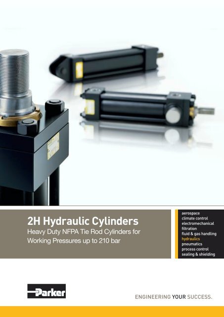
2H Hydraulic Cylinders NFPA tie rod 210 bar - SE Hydraulics
2H Hydraulic Cylinders NFPA tie rod 210 bar - SE Hydraulics
2H Hydraulic Cylinders NFPA tie rod 210 bar - SE Hydraulics

Create successful ePaper yourself
Turn your PDF publications into a flip-book with our unique Google optimized e-Paper software.
<strong>2H</strong> <strong>Hydraulic</strong> <strong>Cylinders</strong><br />
Heavy Duty <strong>NFPA</strong> Tie Rod <strong>Cylinders</strong> for<br />
Working Pressures up to <strong>210</strong> <strong>bar</strong>
Catalogue HY07-1110/UK<br />
Mounting Styles<br />
<strong>2H</strong> Cylinder Mounting Styles<br />
The standard range of Parker <strong>2H</strong> cylinders comprises 17<br />
mounting styles. Dimensional information for each mounting<br />
style is shown on pages 10-21 for 38.1mm to 203.2mm (1 1 / 2" to<br />
8") bore sizes, and on pages 22-25 for 254mm and 304.8mm<br />
(10" and 12") bore sizes.<br />
Tie Rod <strong>Cylinders</strong><br />
<strong>2H</strong> Series<br />
Application-specific mounting information is shown on page 31.<br />
Where a non-standard mounting style is required, please<br />
contact the factory for details.<br />
<strong>NFPA</strong> MX3 <strong>NFPA</strong> MX2 <strong>NFPA</strong> MX1<br />
TB TC TD<br />
<strong>NFPA</strong> MF1 <strong>NFPA</strong> MF5 <strong>NFPA</strong> ME5<br />
J JB JJ<br />
<strong>NFPA</strong> MF2 <strong>NFPA</strong> MF6 <strong>NFPA</strong> ME6<br />
H HB HH<br />
<strong>NFPA</strong> MS2 <strong>NFPA</strong> MS4 <strong>NFPA</strong> MS7<br />
C F G<br />
<strong>NFPA</strong> MP1 ISO 6982 and <strong>NFPA</strong> MT1<br />
CETOP RP88H<br />
BB SBa D<br />
<strong>NFPA</strong> MT2<br />
<strong>NFPA</strong> MT4<br />
DB<br />
DD<br />
K<br />
(KTB shown)<br />
Most mounting styles<br />
are available as double<br />
<strong>rod</strong> cylinders<br />
2 Parker Hannifin<br />
Cylinder Division<br />
Europe
Catalogue HY07-1110/UK<br />
Piston Rod End Data<br />
38.1mm to 203.2mm (1 1 / 2 " to 8") Bores Only<br />
Rod End Styles 4, 7 & 8<br />
– All Except JJ Mount<br />
A<br />
W<br />
V<br />
Rod End Style 9<br />
– All Except JJ Mount<br />
W<br />
V<br />
Tie Rod <strong>Cylinders</strong><br />
<strong>2H</strong> Series<br />
Rod End Styles 4 & 8<br />
The standard <strong>rod</strong> end, Style 4, is recommended for all<br />
applications in which the work piece is secured against the <strong>rod</strong><br />
shoulder. Where the work piece is not shouldered, Style 8 <strong>rod</strong><br />
ends are recommended.<br />
Rod End Style 9<br />
For applications where a female thread is required.<br />
B NA<br />
KK<br />
D<br />
Wrench Flats<br />
MM<br />
B NA<br />
KK<br />
D<br />
Wrench Flats<br />
A<br />
MM<br />
Rod End Style 3<br />
Non-standard piston <strong>rod</strong> ends are designated ‘Style 3’.<br />
A dimensional sketch or description should accompany the<br />
order. Please specify dimensions KK and A.<br />
Rod End Styles 4, 7 & 8<br />
– JJ Mount Only<br />
A1<br />
WF<br />
Rod End Style 9<br />
– JJ Mount Only<br />
WF<br />
RT<br />
Rod End Style 7<br />
Style 7 <strong>rod</strong> ends apply to <strong>rod</strong> eyes with spherical bearings<br />
only (see pages 27 and 29). The Style 7 <strong>rod</strong> end with spherical<br />
bearing allows the same diameter pivot pin to be used at both<br />
the head and cap ends of the cylinder. For Style 7 <strong>rod</strong> end<br />
thread lengths, please refer to dimension A1 in the table below.<br />
RD<br />
RD<br />
Style JJ<br />
Dimensions which are not shown are identical to those shown<br />
for the equivalent non-JJ design.<br />
RT<br />
A1<br />
Rod End Dimensions – 38.1mm to 203.2mm (1 1 / 2 " to 8") bore sizes only<br />
Bore<br />
Ø<br />
38.1<br />
(1 1 / 2")<br />
50.8<br />
(2")<br />
63.5<br />
(2 1 / 2")<br />
82.6<br />
(3 1 / 4")<br />
101.6<br />
(4")<br />
127.0<br />
(5")<br />
152.4<br />
(6")<br />
177.8<br />
(7")<br />
203.2<br />
(8")<br />
Rod<br />
No.<br />
1<br />
2<br />
1<br />
2<br />
1<br />
2<br />
3<br />
1<br />
2<br />
3<br />
1<br />
2<br />
3<br />
1<br />
2<br />
3<br />
4<br />
1<br />
2<br />
3<br />
4<br />
1<br />
2<br />
3<br />
4<br />
1<br />
2<br />
3<br />
5<br />
MM<br />
Rod<br />
Diameter<br />
15.9 ( 5 / 8")<br />
25.4 (1")<br />
25.4 (1")<br />
34.9 (1 3 / 8")<br />
25.4 (1")<br />
44.5 (1 3 / 4")<br />
34.9 (1 3 / 8")<br />
34.9 (1 3 / 8")<br />
50.8 (2")<br />
44.5 (1 3 / 4")<br />
44.5 (1 3 / 4")<br />
63.5 (2 1 / 2")<br />
50.8 (2")<br />
50.8 (2")<br />
88.9 (3 1 / 2")<br />
63.5 (2 1 / 2")<br />
76.2 (3")<br />
63.5 (2 1 / 2")<br />
101.6 (4")<br />
76.2 (3")<br />
88.9 (3 1 / 2")<br />
76.2 (3")<br />
127.0 (5")<br />
88.9 (3 1 / 2")<br />
101.6 (4")<br />
88.9 (3 1 / 2")<br />
139.7 (5 1 / 2")<br />
101.6 (4")<br />
127.0 (5")<br />
Style 4 & 9 Style 8 Style 7 2<br />
KK KK KK KK KK<br />
A B +0.00<br />
A1<br />
-0.05<br />
Metric UNF 1 Metric UNF Metric<br />
M10x1.5<br />
M20x1.5<br />
M20x1.5<br />
M26x1.5<br />
M20x1.5<br />
M33x2<br />
M26x1.5<br />
M26x1.5<br />
M39x2<br />
M33x2<br />
M33x2<br />
M48x2<br />
M39x2<br />
M39x2<br />
M64x2<br />
M48x2<br />
M58x2<br />
M48x2<br />
M76x2<br />
M58x2<br />
M64x2<br />
M58x2<br />
M90x2<br />
M64x2<br />
M76x2<br />
M64.2<br />
M100x2<br />
M76x2<br />
M90x2<br />
7<br />
/ 16 - 20<br />
3<br />
/ 4 - 16<br />
3<br />
/ 4 - 16<br />
1 - 14<br />
3<br />
/ 4 - 16<br />
1 1 / 4 - 12<br />
1 - 14<br />
1 - 14<br />
1 1 / 2 - 12<br />
1 1 / 4 - 12<br />
1 1 / 4 - 12<br />
1 7 / 8 - 12<br />
1 1 / 2 - 12<br />
1 1 / 2 - 12<br />
2 1 / 2 - 12<br />
1 7 / 8 - 12<br />
2 1 / 4 - 12<br />
1 7 / 8 - 12<br />
3 - 12<br />
2 1 / 4 - 12<br />
2 1 / 2 - 12<br />
2 1 / 4 - 12<br />
3 1 / 2 - 12<br />
2 1 / 2 - 12<br />
3 - 12<br />
2 1 / 2 - 12<br />
4 - 12<br />
3 - 12<br />
3 1 / 2 - 12<br />
M12x1.5<br />
M22x1.5<br />
M22x1.5<br />
M30x2<br />
M22x1.5<br />
M39x2<br />
M30x2<br />
M30x2<br />
M45x2<br />
M39x2<br />
M39x2<br />
M56x2<br />
M45x2<br />
M45x2<br />
M76x2<br />
M56x2<br />
M68x2<br />
M56x2<br />
M95x2<br />
M68x2<br />
M76x2<br />
M68x2<br />
M110x2<br />
M76x2<br />
M95x2<br />
M76x2<br />
M130x2<br />
M95x2<br />
M110x2<br />
All dimensions are in millimetres unless otherwise stated.<br />
1<br />
/ 2 - 20<br />
7<br />
/ 8 - 14<br />
7<br />
/ 8 - 14<br />
1 / 4 - 12<br />
7<br />
/ 8 - 14<br />
1 / 2 - 12<br />
1 / 4 - 12<br />
1 1 / 4 - 12<br />
1 3 / 4 - 12<br />
1 1 / 2 - 12<br />
1 1 / 2 - 12<br />
2 1 / 4 - 12<br />
1 3 / 4 - 12<br />
1 3 / 4 - 12<br />
3 1 / 4 - 12<br />
2 1 / 4 - 12<br />
2 3 / 4 - 12<br />
2 1 / 4 - 12<br />
3 3 / 4 - 12<br />
2 3 / 4 - 12<br />
3 1 / 4 - 12<br />
2 3 / 4 - 12<br />
4 3 / 4 - 12<br />
3 1 / 4 - 12<br />
3 3 / 4 - 12<br />
3 1 / 4 - 12<br />
5 1 / 4 - 12<br />
3 3 / 4 - 12<br />
4 3 / 4 - 12<br />
–<br />
M16x1.5<br />
M20x1.5<br />
M20x1.5<br />
–<br />
M27x2<br />
M27x2<br />
–<br />
M33x2<br />
M33x2<br />
–<br />
M42x2<br />
M42x2<br />
–<br />
M48x2<br />
M48x2<br />
–<br />
–<br />
M64x3<br />
–<br />
M64x3<br />
–<br />
–<br />
–<br />
–<br />
–<br />
–<br />
–<br />
–<br />
21<br />
27<br />
35<br />
44<br />
55<br />
62<br />
84<br />
–<br />
–<br />
19.0<br />
28.6<br />
28.6<br />
41.3<br />
28.6<br />
50.8<br />
41.3<br />
41.3<br />
57.1<br />
50.8<br />
50.8<br />
76.2<br />
57.1<br />
57.1<br />
88.9<br />
76.2<br />
88.9<br />
76.2<br />
101.6<br />
88.9<br />
88.9<br />
88.9<br />
127.0<br />
88.9<br />
101.6<br />
88.9<br />
139.7<br />
101.6<br />
127.0<br />
28.55<br />
38.07<br />
38.07<br />
50.77<br />
38.07<br />
60.30<br />
50.77<br />
50.77<br />
66.65<br />
60.30<br />
60.30<br />
79.35<br />
66.65<br />
66.65<br />
107.92<br />
79.35<br />
95.22<br />
79.35<br />
120.62<br />
95.22<br />
107.92<br />
95.22<br />
146.02<br />
107.92<br />
120.62<br />
107.92<br />
158.72<br />
120.62<br />
146.02<br />
D NA V W<br />
13<br />
22<br />
22<br />
30<br />
22<br />
36<br />
30<br />
30<br />
41<br />
36<br />
36<br />
55<br />
41<br />
41<br />
75<br />
55<br />
65<br />
55<br />
85<br />
65<br />
75<br />
65<br />
110<br />
75<br />
85<br />
75<br />
120<br />
85<br />
110<br />
14.3<br />
23.8<br />
23.8<br />
33.3<br />
23.8<br />
42.9<br />
33.3<br />
33.3<br />
49.2<br />
42.9<br />
42.9<br />
60.3<br />
49.2<br />
49.2<br />
85.7<br />
60.3<br />
73.0<br />
60.3<br />
98.4<br />
73.0<br />
85.7<br />
73.0<br />
123.8<br />
85.7<br />
98.4<br />
85.7<br />
136.5<br />
98.4<br />
123.8<br />
6.4<br />
12.7<br />
6.4<br />
9.5<br />
6.4<br />
12.7<br />
9.5<br />
6.4<br />
9.5<br />
9.5<br />
6.4<br />
9.5<br />
6.4<br />
6.4<br />
9.5<br />
9.5<br />
9.5<br />
6.4<br />
6.4<br />
6.4<br />
6.4<br />
6.4<br />
6.4<br />
6.4<br />
6.4<br />
6.4<br />
6.4<br />
6.4<br />
6.4<br />
15.9<br />
25.4<br />
19.1<br />
25.4<br />
19.1<br />
31.8<br />
25.4<br />
22.2<br />
31.8<br />
28.6<br />
25.4<br />
34.9<br />
28.6<br />
28.6<br />
34.9<br />
34.9<br />
34.9<br />
31.8<br />
31.8<br />
31.8<br />
31.8<br />
31.8<br />
31.8<br />
31.8<br />
31.8<br />
31.8<br />
31.8<br />
31.8<br />
31.8<br />
1<br />
All <strong>rod</strong> threads are UNF except 1" - 14 which is UNS.<br />
2<br />
Style 7 threads apply to spherical <strong>rod</strong> eyes only, see pages 27 and 29.<br />
3 Parker Hannifin<br />
Cylinder Division<br />
Europe<br />
JJ Mount Only<br />
RD<br />
RT WF<br />
max.<br />
54.0<br />
63.5<br />
63.5<br />
76.2<br />
63.5<br />
88.9<br />
76.2<br />
76.2<br />
101.6<br />
88.9<br />
88.9<br />
114.3<br />
101.6<br />
101.6<br />
146.1<br />
114.3<br />
133.4<br />
114.3<br />
165.1<br />
133.4<br />
146.1<br />
133.4<br />
190.5<br />
146.1<br />
165.1<br />
146.1<br />
209.6<br />
165.1<br />
190.5<br />
9.5<br />
9.5<br />
9.5<br />
9.5<br />
9.5<br />
9.5<br />
9.5<br />
9.5<br />
15.9<br />
9.5<br />
9.5<br />
15.9<br />
15.9<br />
15.9<br />
15.9<br />
15.9<br />
15.9<br />
15.9<br />
19.1<br />
15.9<br />
15.9<br />
15.9<br />
25.4<br />
15.9<br />
19.1<br />
15.9<br />
19.1<br />
19.1<br />
25.4<br />
25.4<br />
35.0<br />
35.0<br />
41.3<br />
35.0<br />
47.7<br />
41.3<br />
41.3<br />
50.8<br />
47.7<br />
47.7<br />
57.2<br />
50.8<br />
50.8<br />
57.2<br />
57.2<br />
57.2<br />
57.2<br />
57.2<br />
57.2<br />
57.2<br />
57.2<br />
57.2<br />
57.2<br />
57.2<br />
57.2<br />
57.2<br />
57.2<br />
57.2
Catalogue HY07-1110/UK<br />
Storage and Installation, Cylinder Masses<br />
Tie Rod <strong>Cylinders</strong><br />
<strong>2H</strong> Series<br />
Storage<br />
When cylinders must be stored for a period of time, the<br />
following procedures are recommended:<br />
1. Store the cylinders in an indoor area which has a dry, clean<br />
and non-corrosive atmosphere. Take care to protect the<br />
cylinder from both internal corrosion and external damage.<br />
2. Whenever possible, cylinders should be stored in a vertical<br />
position (piston <strong>rod</strong> up). This will minimize corrosion due to<br />
possible condensation which could occur inside the cylinder.<br />
3. Port protector plugs should be left in the cylinder until the<br />
time of installation.<br />
Installation<br />
1. Cleanliness is an important consideration, and Parker<br />
cylinders are shipped with the ports plugged to protect them<br />
from contaminants entering the ports. These plugs should<br />
not be removed until the piping is to be installed. Before<br />
making the connection to the cylinder ports, piping should<br />
be thoroughly cleaned to remove all debris which might have<br />
resulted from threading or flaring operations.<br />
2. <strong>Cylinders</strong> operating in an environment where air drying<br />
materials are present such as fast-drying chemicals, paint,<br />
or weld splatter, or other hazardous conditions such as<br />
excessive heat, should have shields installed to prevent<br />
damage to the piston <strong>rod</strong> and piston <strong>rod</strong> seals.<br />
3. Correct alignment of the cylinder piston <strong>rod</strong> and its mating<br />
component on the machine should be checked in both the<br />
extended and retracted positions. Incorrect alignment will<br />
result in excessive <strong>rod</strong> gland and/or cylinder bore wear,<br />
shortening the life of the cylinder.<br />
Masses – Series <strong>2H</strong> <strong>Cylinders</strong><br />
To determine the mass of the cylinder, first select the basic<br />
mass for zero stroke, then calculate and add the mass for the<br />
appropriate stroke length. Masses for accessories are shown on<br />
pages 27 to 29.<br />
Bore<br />
Ø<br />
38.1<br />
(1 1 / 2")<br />
50.8<br />
(2")<br />
63.5<br />
(2 1 / 2")<br />
82.6<br />
(3 1 / 4")<br />
101.6<br />
(4")<br />
127.0<br />
(5")<br />
152.4<br />
(6")<br />
177.8<br />
(7")<br />
203.2<br />
(8")<br />
254.0<br />
(10")<br />
304.8<br />
(12")<br />
Rod<br />
No.<br />
1<br />
2<br />
1<br />
2<br />
1<br />
2<br />
3<br />
1<br />
2<br />
3<br />
1<br />
2<br />
3<br />
1<br />
2<br />
3<br />
4<br />
1<br />
2<br />
3<br />
4<br />
1<br />
2<br />
3<br />
4<br />
1<br />
2<br />
3<br />
5<br />
1<br />
2<br />
1<br />
2<br />
Single Rod <strong>Cylinders</strong><br />
Mass at Zero Stroke<br />
Mounting Styles<br />
TB, TC,<br />
TD, J, JB,<br />
H, HB, F<br />
kg<br />
3.6<br />
3.7<br />
5.7<br />
6.0<br />
7.9<br />
8.7<br />
8.2<br />
15.2<br />
16.1<br />
15.7<br />
20.4<br />
22.2<br />
20.8<br />
36<br />
41<br />
37<br />
39<br />
58<br />
64<br />
60<br />
62<br />
86<br />
97<br />
88<br />
90<br />
120<br />
135<br />
123<br />
130<br />
275<br />
291<br />
444<br />
474<br />
JJ, HH, D,<br />
DB, DD, C,<br />
G, SBa, BB<br />
kg<br />
4.7<br />
4.9<br />
7.5<br />
7.8<br />
10.1<br />
11.0<br />
10.8<br />
19.4<br />
20.4<br />
19.9<br />
25.7<br />
27.5<br />
26<br />
44<br />
49<br />
46<br />
47<br />
71<br />
77<br />
73<br />
75<br />
105<br />
116<br />
107<br />
109<br />
145<br />
160<br />
148<br />
155<br />
328<br />
344<br />
527<br />
557<br />
Mass<br />
per<br />
10mm<br />
Stroke<br />
kg<br />
0.09<br />
0.11<br />
0.14<br />
0.18<br />
0.19<br />
0.27<br />
0.22<br />
0.31<br />
0.39<br />
0.36<br />
0.39<br />
0.51<br />
0.42<br />
0.59<br />
0.92<br />
0.68<br />
0.79<br />
0.92<br />
1.3<br />
1.1<br />
1.2<br />
1.2<br />
1.8<br />
1.3<br />
1.4<br />
1.6<br />
2.3<br />
1.8<br />
2.1<br />
3.0<br />
4.0<br />
3.9<br />
5.6<br />
Double Rod <strong>Cylinders</strong><br />
Mass at Zero Stroke<br />
Mounting Styles<br />
TB, TD,<br />
J, JB, F<br />
kg<br />
4.1<br />
4.4<br />
6.9<br />
7.5<br />
9.4<br />
11.0<br />
10.0<br />
18.2<br />
20.0<br />
19.2<br />
25<br />
29<br />
26<br />
43<br />
53<br />
46<br />
49<br />
68<br />
80<br />
71<br />
74<br />
99<br />
122<br />
103<br />
108<br />
137<br />
166<br />
142<br />
157<br />
325<br />
357<br />
519<br />
579<br />
JJ, C, G,<br />
D, DD<br />
kg<br />
5.23<br />
5.53<br />
8.74<br />
9.34<br />
11.7<br />
13.3<br />
12.7<br />
22.5<br />
24.3<br />
23.5<br />
31<br />
35<br />
32<br />
52<br />
62<br />
55<br />
58<br />
82<br />
94<br />
85<br />
88<br />
119<br />
142<br />
123<br />
128<br />
163<br />
192<br />
168<br />
183<br />
378<br />
410<br />
603<br />
663<br />
Mass<br />
per<br />
10mm<br />
Stroke<br />
kg<br />
0.10<br />
0.15<br />
0.18<br />
0.25<br />
0.23<br />
0.39<br />
0.30<br />
0.39<br />
0.55<br />
0.48<br />
0.51<br />
0.76<br />
0.58<br />
0.75<br />
1.40<br />
0.93<br />
1.20<br />
1.2<br />
2.0<br />
1.4<br />
1.7<br />
1.5<br />
2.8<br />
1.8<br />
2.1<br />
2.1<br />
3.5<br />
2.4<br />
3.1<br />
4.0<br />
5.9<br />
5.1<br />
8.4<br />
Warning<br />
FAILURE OR IMPROPER <strong>SE</strong>LECTION OR IMPROPER U<strong>SE</strong> OF THE PRODUCTS AND/OR SYSTEMS DESCRIBED HEREIN OR RELATED<br />
ITEMS CAN CAU<strong>SE</strong> DEATH, PERSONAL INJURY AND PROPERTY DAMAGE.<br />
This document and other information from Parker Hannifin Corporation, its subsidiaries, sales offices and authorized distributors provide<br />
p<strong>rod</strong>uct or system options for further investigation by users having technical expertise. Before you select or use any p<strong>rod</strong>uct or system it is<br />
important that you analyse all aspects of your application and review the information concerning the p<strong>rod</strong>uct or system in the current p<strong>rod</strong>uct<br />
catalogue. Due to the variety of operating conditions and applications for these p<strong>rod</strong>ucts or systems, the user, through his own analysis<br />
and testing, is solely responsible for making the final selection of the p<strong>rod</strong>ucts and systems and assuring that all performance and safety<br />
requirements of the application are met.<br />
The p<strong>rod</strong>ucts described herein, including without limitation, p<strong>rod</strong>uct features, specifications, designs, availability and pricing, are subject to<br />
change by Parker Hannifin Corporation and its subsidiaries at any time without notice.<br />
Offer of Sale<br />
Please contact your local Parker representative for a detailed offer of sale.<br />
All dimensions are in millimetres unless otherwise stated.<br />
4 Parker Hannifin<br />
Cylinder Division<br />
Europe
Catalogue HY07-1110/UK<br />
Int<strong>rod</strong>uction<br />
Parker Offers the Widest Range of<br />
Industrial <strong>Cylinders</strong><br />
High P<strong>rod</strong>uctivity – Low Cost of Ownership<br />
Parker Hannifin’s Cylinder Division is the world’s largest supplier<br />
of hydraulic cylinders for industrial applications.<br />
Parker manufactures a vast range of standard and special<br />
<strong>tie</strong> <strong>rod</strong>, roundline and ‘mill’ type cylinders to suit all types of<br />
industrial cylinder applications. Our cylinders are available to ISO,<br />
DIN, <strong>NFPA</strong>, ANSI and JIC standards, with other certifications<br />
available on request. All Parker hydraulic cylinders are<br />
designed to deliver long, efficient service with low maintenance<br />
requirements, guaranteeing high p<strong>rod</strong>uctivity year after year.<br />
About Parker Hannifin<br />
Parker Hannifin is the global leader in motion and control<br />
technologies, partnering with its customers to increase<br />
their p<strong>rod</strong>uctivity and profitability. The company employs<br />
more than 52,000 people in 48 countries around the world,<br />
providing customers with technical excellence and first class<br />
customer service.<br />
Visit us at www.parker.com<br />
Tie Rod <strong>Cylinders</strong><br />
<strong>2H</strong> Series<br />
Contents<br />
Page<br />
Piston Rod End Data –<br />
38.1mm to 203.2mm (1 1 / 2" to 8") bores 3<br />
Storage Information & Mass Data 4<br />
Standard Specifications 5<br />
Design Features and Benefits 6<br />
Cylinder Selection Check List 8<br />
Mounting Styles 9<br />
Double Rod <strong>Cylinders</strong> 26<br />
Accessories 27<br />
Mounting Information 30<br />
Push and Pull Forces 32<br />
Piston Rod Sizes & Stop Tubes 33<br />
Stroke Factors & Long Stroke <strong>Cylinders</strong> 34<br />
Cushioning 35<br />
Pressure Limitations 36<br />
Ports, Locations and Piston Speeds 36<br />
Seals & Fluids 38<br />
Optional Features 39<br />
Replacement Parts and Service 40<br />
Repairs 41<br />
Piston Rod End Data –<br />
254.0mm and 304.8mm (10" and 12") bores 42<br />
How to Order <strong>Cylinders</strong> 43<br />
The <strong>2H</strong> Cylinder Range<br />
The <strong>2H</strong> cylinders described in this catalogue are heavy duty<br />
hydraulic cylinders rated for use at working pressures up to <strong>210</strong><br />
<strong>bar</strong> depending on the <strong>rod</strong> end and type of service.<br />
In addition to the standard cylinders featured in this catalogue,<br />
<strong>2H</strong> cylinders can be designed to suit customer requirements.<br />
Our engineers will be pleased to advise on unique designs to<br />
suit specific applications.<br />
inPHorm and 3-D CAD<br />
Parker offers easy-to-use software to simplify the cylinder<br />
selection process, saving your time and ensuring the accuracy<br />
of designs and drawings. InPHorm selection software and new<br />
3-D CAD modelling software can be downloaded from our<br />
Cylinder Division Europe website.<br />
Please visit us at www.parker.com or contact your local Sales<br />
Office for more information.<br />
Standard Specifications<br />
• Heavy-duty service – ANSI B93.15-1987 and <strong>NFPA</strong><br />
specifications<br />
• Standard construction – square end, <strong>tie</strong> <strong>rod</strong> design<br />
• Standard pressure – <strong>210</strong> <strong>bar</strong><br />
• Standard fluid – hydraulic mineral oil<br />
• Standard temperature – -20°C to 80°C (-4°F to 176°F)<br />
• Bore sizes – 38.1mm (1 1 / 2") to 304.8mm (12")<br />
• Piston <strong>rod</strong> diameters – 15.9mm ( 5 / 8") to 215.9mm (8 1 / 2")<br />
• Mounting styles – 17 standard styles<br />
• Strokes – available in any practical stroke length<br />
• Cushions – optional at either end or both ends of stroke<br />
• Rod ends – three standard choices – specials to order<br />
5 Parker Hannifin<br />
Cylinder Division<br />
Europe
Catalogue HY07-1110/UK<br />
Design Features and Benefits<br />
Tie Rod <strong>Cylinders</strong><br />
<strong>2H</strong> Series<br />
3<br />
2<br />
5<br />
6<br />
10<br />
8<br />
1<br />
1 Piston Rod<br />
Gland seal life is maximised by manufacturing piston <strong>rod</strong>s from<br />
precision ground, high tensile carbon alloy steel, hard chrome<br />
plated and polished to 0.2µm max. Piston <strong>rod</strong>s are induction<br />
case hardened to Rockwell C54 minimum before chrome<br />
plating, resulting in a dent-resistant surface.<br />
2 Parker’s Rod Gland<br />
Continuous lubrication, and therefore longer gland life, are<br />
provided by the long bearing surface inboard of the lipseal. The<br />
gland, complete with <strong>rod</strong> seals, can easily be removed without<br />
dismantling the cylinder, so servicing is quicker – and therefore<br />
more economical.<br />
3 Rod Seals<br />
The serrated lipseal has a series of sealing edges which take<br />
over successively as pressure increases, providing efficient<br />
sealing under all operating conditions. On the return stroke the<br />
serrations act as a check valve, allowing the oil adhering to the<br />
<strong>rod</strong> to pass back into the cylinder.<br />
The double lip wiperseal acts as a secondary seal, trapping<br />
excess lubricating film in the chamber between the wiper and lip<br />
seals and preventing the ingress of dirt into the cylinder, extending<br />
the life of gland and seals. Standard lipseals are manufactured<br />
from an enhanced polyurethane, giving efficient retention of<br />
11<br />
12<br />
7<br />
4 9 & 10<br />
9 11<br />
fluid and a life of up to five times that of traditional seal materials.<br />
Standard <strong>rod</strong> seals are suitable for speeds up to 0.5m/s – special<br />
seal combinations are available for higher speed applications.<br />
4 Cylinder Body<br />
Strict quality control standards and precision manufacture<br />
ensure that all tubes meet rigid standards of straightness,<br />
roundness and surface finish. The steel tubing is surface<br />
finished to minimise internal friction and prolong seal life.<br />
5 Cylinder Body Seals<br />
To ensure that the cylinder body remains leak free, even under<br />
pressure shock conditions, Parker fits pressure-energised<br />
body seals.<br />
6 Piston<br />
All pistons are of one-piece type, and feature wide bearing<br />
surfaces to resist side loading. Long thread engagement secures<br />
the piston to the piston <strong>rod</strong> and, for additional safety, the piston<br />
is secured by thread-locking adhesive and a locking pin.<br />
7 Piston Seals<br />
Cast Iron Piston Rings are extremely durable but allow some<br />
leakage across the piston and cannot therefore hold a load in<br />
position. Cast iron piston rings are fitted as standard on series<br />
<strong>2H</strong> hydraulic cylinders.<br />
Lipseal Pistons can hold a load in position, but are not as<br />
durable as pistons with cast iron rings or Hi-Load seals. For<br />
applications with a working pressure in excess of 140 <strong>bar</strong> where<br />
the duty cycle requires sustained piston speeds in excess of<br />
0.4m/s or high cycling performance, other seal options should<br />
also be considered. Where these performance criteria may<br />
be exceeded, please contact the factory with details of the<br />
application.<br />
Hi-Load Pistons resist side loading and are recommended for<br />
long stroke cylinders, especially when pivot mounted. Special<br />
wear rings prevent metal-to-metal contact between the piston<br />
and tube and thereby extend the life of the cylinder.<br />
Low Friction Seals are also available – see page 37.<br />
6 Parker Hannifin<br />
Cylinder Division<br />
Europe
Catalogue HY07-1110/UK<br />
Features and Benefits<br />
8 Ports<br />
High piston speeds allow rapid cycling, which maximises<br />
machine p<strong>rod</strong>uctivity. Parker offers a range of port sizes to<br />
permit different flow rates, in all common inch and metric<br />
standards. Choosing the correct port size simplifies design and<br />
installation, and cuts maintenance time to a minimum.<br />
9 Cushioning<br />
Progressive deceleration reduces both noise and shock,<br />
prolonging machine life and improving the working environment.<br />
Parker <strong>2H</strong> cylinders are available with stepped cushions at the<br />
head and cap, which decelerate a load safely while optimising<br />
the cycling rate of the process. The head and cap end cushions<br />
are self centring. The polished cap end spear is an integral part<br />
of the piston <strong>rod</strong>.<br />
Tie Rod <strong>Cylinders</strong><br />
<strong>2H</strong> Series<br />
Seal Classes<br />
To accommodate the many types of fluid and the varying<br />
temperature ranges used in industry, Parker offers a range of<br />
<strong>rod</strong> gland, piston and body seals moulded in different profiles<br />
and from different materials. These are described in detail on<br />
page 37.<br />
Special Designs<br />
Parker’s design and engineering staff are available to p<strong>rod</strong>uce<br />
special designs to meet customer’s specific requirements.<br />
Alternative sealing arrangements, special mounting styles,<br />
different bores and <strong>rod</strong> sizes are just a few of the custom<br />
features which can be supplied.<br />
10 Floating Cushion Bushes & Sleeves<br />
Closer tolerances – and therefore more effective cushioning<br />
– are permitted by the use of a floating cushion sleeve at the<br />
head end of the cylinder, and a floating cushion bush at the cap<br />
end. A specially designed cushion sleeve on bore sizes up to<br />
101.6mm (4") operates as a check valve. On larger bore sizes a<br />
conventional ball check valve is used. The use of a check valve<br />
in the head and lifting of the bronze cushion bush in the cap,<br />
provides minimum fluid flow restriction at the start of the return<br />
stroke. This allows full pressure to be applied over the whole<br />
area of the piston, to provide full power and fast cycle times.<br />
11 Cushion Adjustment<br />
Needle valves are provided at<br />
both ends of the cylinder for<br />
precise cushion adjustment,<br />
and retained within the head<br />
and cap so that they cannot<br />
be inadvertently removed.<br />
The cartridge type needle<br />
valve illustrated is fitted to<br />
cylinders of up to 63.5mm<br />
(2 1 / 2") bore. See page 35 for<br />
location.<br />
12 Tie Rod Construction<br />
Tie <strong>rod</strong> construction, with <strong>tie</strong> <strong>rod</strong>s torque-loaded on assembly,<br />
imposes a compressive force on the cylinder tube which<br />
counters the tensile forces generated by system pressure.<br />
The result – a fatigue-free cylinder with long service life and<br />
exceptionally compact dimensions.<br />
7 Parker Hannifin<br />
Cylinder Division<br />
Europe
Catalogue HY07-1110/UK<br />
Optional Features<br />
Air Bleeds<br />
The option of air bleeds is available<br />
at either or both ends of the<br />
cylinder, at any position except<br />
in the port face – see page 35 for<br />
location. To ensure operator safety,<br />
the standard M8 air bleed screw<br />
(illustrated) is recessed into the<br />
head and cap and retained so that it<br />
cannot be inadvertently removed.<br />
Gland Drains<br />
The accumulation of fluid between the gland seals of long<br />
stroke cylinders, cylinders with constant back pressure or where<br />
the ratio of the extend speed to the retract speed is greater<br />
than 2 to 1, can be relieved by specifying an optional gland<br />
drain. A transparent tube fitted between the gland drain and<br />
the reservoir allows fluid loss from concealed or inaccessible<br />
cylinders to be monitored, giving an early indication of the need<br />
for gland servicing.<br />
A 1 / 8" NPTF gland drain port can be provided in the retainer on<br />
all cylinders up to and including 203.2mm (8") bore sizes, except<br />
38.1mm (1 1 / 2") with no. 1 <strong>rod</strong>. For 38.1mm (1 1 / 2") bore cylinders<br />
with no.2 <strong>rod</strong>, the retainer thickness is increased to 15.9mm<br />
( 5 / 8"). For 38.1mm (1 1 / 2") bore cylinders with no.1 <strong>rod</strong>, the drain<br />
port is located in the head end adjacent to the port.<br />
Stroke Limiters<br />
Where absolute precision in stroke length is required, a screwed<br />
adjustable stop can be supplied at the cap end. Several types<br />
are available – the illustration<br />
shows a design suitable for<br />
infrequent adjustment of<br />
an uncushioned cylinder.<br />
Please contact the factory,<br />
specifying details of<br />
the application and the<br />
adjustment required.<br />
L<br />
K<br />
Seal<br />
J<br />
Wrench<br />
Square<br />
Tie Rod <strong>Cylinders</strong><br />
<strong>2H</strong> Series<br />
Rod Locking Devices<br />
These units provide positive locking of the piston <strong>rod</strong>. They<br />
require hydraulic pressure to release, while loss of pressure<br />
causes the clamp to operate, allowing them to be used as a failsafe<br />
device. Please consult the factory for further information.<br />
Single-Acting <strong>Cylinders</strong><br />
Standard <strong>2H</strong> series cylinders are of the double-acting type.<br />
They are also suitable for use as single-acting cylinders, where<br />
the load or other external force is used to return the piston after<br />
the pressure stroke. Cast iron piston rings should not be used<br />
with single-acting cylinders.<br />
Spring-Returned, Single-Acting <strong>Cylinders</strong><br />
Single-acting cylinders can be supplied with an internal spring<br />
to return the piston after the pressure stroke. Please supply<br />
details of load conditions and friction factors, and advise whether<br />
the spring is required to advance or return the piston <strong>rod</strong>.<br />
On spring-returned cylinders, it is recommended that <strong>tie</strong> <strong>rod</strong><br />
extensions be specified to allow the spring to be ‘backed off’<br />
until compression is relieved. Please consult the factory when<br />
ordering spring-returned cylinders.<br />
Multiple Stroke Positioning<br />
To obtain linear force in one plane with controlled stopping<br />
at intermediate points, several designs are available. For<br />
three stopped positions, it is common practice to mount two<br />
standard single <strong>rod</strong> Style H cylinders back-to-back, or to use<br />
through-<strong>tie</strong> <strong>rod</strong>s. By extending or retracting the stroke of each<br />
cylinder independently, it is possible to achieve three positions<br />
at the piston ends. An alternative technique is to use a tandem<br />
cylinder with an independent piston <strong>rod</strong> in the cap section.<br />
Please consult the factory for further details.<br />
Rod End Bellows<br />
Unprotected piston <strong>rod</strong> surfaces which are exposed to<br />
contaminants with air hardening proper<strong>tie</strong>s should be protected<br />
by <strong>rod</strong> end bellows. Longer <strong>rod</strong> extensions are required to<br />
accommodate the collapsed length of the bellows. Please<br />
consult the factory for further information.<br />
Metallic Rod Wipers<br />
Metallic <strong>rod</strong> wipers replace the standard wiper seal, and are<br />
recommended where dust, ice or splashings might damage the<br />
wiper seal material. They do not affect cylinder dimensions.<br />
Bore<br />
Ø<br />
38.1 (1 1 / 2")<br />
50.8 (2")<br />
63.5 (2 1 / 2")<br />
82.6 (3 1 / 4")<br />
101.6 (4")<br />
127.0 (5")<br />
152.4 (6")<br />
177.8 (7")<br />
203.2 (8")<br />
K<br />
L<br />
J<br />
min.<br />
max.<br />
11 55 127.0<br />
17 75 203.2<br />
17 75 228.6<br />
22 85 228.6<br />
24 70 457.2<br />
32 70 508.0<br />
41 75 508.0<br />
50 75 508.0<br />
60 80 508.0<br />
DC Proximity Sensors<br />
These can be fitted to give precise, repeatable end of stroke<br />
signals. Please contact the factory for details.<br />
Position Feedback<br />
Linear position transducers of various types are available for <strong>2H</strong><br />
series cylinders. Please contact the factory for details.<br />
All dimensions are in millimetres unless otherwise stated.<br />
8 Parker Hannifin<br />
Cylinder Division<br />
Europe
Catalogue HY07-1110/UK<br />
Mounting Styles<br />
Tie Rod <strong>Cylinders</strong><br />
<strong>2H</strong> Series<br />
Mounting Styles and Where to Use Them<br />
See also application-specific mounting information on page 30.<br />
Extended Tie Rod Mountings – Styles TB, TC and TD<br />
Application<br />
• straight line force transfer<br />
• compression (push) – use cap end mountings TC or TD<br />
• tension (pull) – use head end mountings TB or TD<br />
Benefits<br />
• ease of mounting where space is limited<br />
• high efficiency – force is absorbed on cylinder’s centreline<br />
• TD double-ended mounting allows brackets or switches to be<br />
attached to cylinder<br />
Styles TB, TC, TD<br />
See pages 10-11<br />
TB<br />
Flange Mountings – Styles J, JB, JJ, H, HB and HH<br />
Application<br />
• straight line force transfer<br />
• compression (push) – use cap end mounting H, HB or HH<br />
• tension (pull) – use head end mounting J, JB or JJ<br />
Benefits<br />
• exceptionally rigid mounting due to large flange area<br />
• high efficiency – force is absorbed on cylinder's centreline<br />
Foot Mountings – Style C, F, G<br />
Application<br />
• straight line force transfer<br />
• suitable for push or pull applications<br />
• force is not absorbed on centreline – secure attachment, eg: a<br />
thrust key (page 30) and effective load guidance are vital<br />
Benefits<br />
• ease of mounting and adjustment<br />
Pivot Mountings – Styles BB and SBa<br />
Application<br />
• curved path force transfer<br />
• movement in a single plane – use fixed clevis style BB<br />
• movement in more than one plane – use spherical bearing<br />
style SBd<br />
Benefits<br />
• ease of attachment – use with plain or spherical bearing at<br />
<strong>rod</strong> end<br />
• greater flexibility for the machine designer<br />
• self-alignment resists wear of cylinder’s bearing surfaces<br />
Trunnion Mountings – Styles D, DB and DD<br />
Application<br />
• curved path force transfer<br />
• movement in a single plane<br />
• compression (push) – use DB or DD mountings<br />
• tension (pull) – use D or DD mountings<br />
Benefits<br />
• greater flexibility for the machine designer<br />
• self-alignment resists wear of cylinder’s bearing surfaces<br />
• high efficiency – force is absorbed on cylinder’s centreline<br />
• ease of attachment – use with pivot mounting at <strong>rod</strong> end<br />
Styles J, JB, JJ, H, HB, HH<br />
See pages 12-15, 22-23<br />
Styles C, F, G<br />
See pages 16-17 and 25<br />
Styles BB, SBa<br />
See pages 18-19 and 25<br />
Styles D, DB, DD<br />
See pages 20-21 and 24<br />
HH<br />
C<br />
BB<br />
DB<br />
9 Parker Hannifin<br />
Cylinder Division<br />
Europe
Catalogue HY07-1110/UK<br />
Tie Rod Mountings 38.1 - 203.2mm bores<br />
Tie Rod <strong>Cylinders</strong><br />
<strong>2H</strong> Series<br />
Y<br />
ZB + stroke<br />
ZJ + stroke<br />
P + stroke<br />
EE<br />
E<br />
1<br />
AA<br />
E 4<br />
2<br />
R<br />
DD<br />
Style TB<br />
Tie Rods Extended Head End<br />
(<strong>NFPA</strong> Style MX3)<br />
BB<br />
F<br />
G<br />
LB + stroke<br />
J<br />
K<br />
3<br />
R<br />
See Notes 1, 2<br />
Y<br />
ZB + stroke<br />
ZJ + stroke<br />
P + stroke<br />
EE<br />
E<br />
1<br />
AA<br />
E 4<br />
2<br />
R<br />
DD<br />
Style TC<br />
Tie Rods Extended Cap End<br />
(<strong>NFPA</strong> Style MX2)<br />
K<br />
F<br />
G<br />
LB + stroke<br />
J<br />
BB<br />
3<br />
R<br />
See Notes 1, 2<br />
Dimensions TB, TC & TD See also <strong>rod</strong> end dimensions, page 3 & mounting information, page 30<br />
Bore<br />
Ø<br />
38.1<br />
(1 1 / 2")<br />
50.8<br />
(2")<br />
63.5<br />
(2 1 / 2")<br />
82.6<br />
(3 1 / 4")<br />
101.6<br />
(4")<br />
127.0<br />
(5")<br />
152.4<br />
(6")<br />
177.8<br />
(7")<br />
203.2<br />
(8")<br />
Rod<br />
No.<br />
1<br />
2<br />
1<br />
2<br />
1<br />
2<br />
3<br />
1<br />
2<br />
3<br />
1<br />
2<br />
3<br />
1<br />
2<br />
3<br />
4<br />
1<br />
2<br />
3<br />
4<br />
1<br />
2<br />
3<br />
4<br />
1<br />
2<br />
3<br />
5<br />
AA BB DD 1 E<br />
EE<br />
(BSPP)<br />
F G J<br />
58.4 34.9 3<br />
/ 8 - 24 63.5 G 1 / 2 9.5 44.5 38.1<br />
73.7 46.0 1<br />
/ 2 - 20 76.2 G 1 / 2 15.9 44.5 38.1<br />
91.4 46.0 1<br />
/ 2 - 20 88.9 G 1 / 2 15.9 44.5 38.1<br />
116.8 58.7 5<br />
/ 8 - 18 114.3 G 3 / 4 19.1 50.8 44.5<br />
137.2 58.7 5<br />
/ 8 - 18 127.0 G 3 / 4 22.2 50.8 44.5<br />
177.8 81.0 7<br />
/ 8 - 14 165.1 G 3 / 4 22.2 50.8 44.5<br />
205.7 92.1 1 - 14 190.5 G1 25.4 57.2 57.2<br />
236.2 104.8 1 1 / 8 - 12 215.9 G1 1 / 4 25.4 69.9 69.9<br />
269.2 114.3 1 1 / 4 - 12 241.3 G1 1 / 2 25.4 76.2 76.2<br />
All dimensions are in millimetres unless otherwise stated.<br />
10 Parker Hannifin<br />
Cylinder Division<br />
Europe
Catalogue HY07-1110/UK<br />
Tie Rod Mountings 38.1 - 203.2mm bores<br />
Tie Rod <strong>Cylinders</strong><br />
<strong>2H</strong> Series<br />
Y<br />
ZB + stroke<br />
ZJ + stroke<br />
P + stroke<br />
EE<br />
E<br />
1<br />
AA<br />
E 4<br />
2<br />
R<br />
DD<br />
DD<br />
Style TD<br />
Tie Rods Extended Both Ends<br />
(<strong>NFPA</strong> Style MX1)<br />
BB<br />
F<br />
G<br />
LB + stroke<br />
J<br />
BB<br />
3<br />
R<br />
See Notes 1, 2<br />
Notes<br />
1 All <strong>tie</strong> <strong>rod</strong> threads (dimension DD) are UNF, with the exception of 1 - 14 which is UNS<br />
2 Mounting nuts should be tightened to the torque values shown for <strong>tie</strong> <strong>rod</strong> nuts – see page 30<br />
Dimensions TB, TC & TD Continued<br />
Bore<br />
Ø<br />
38.1<br />
(1 1 / 2")<br />
50.8<br />
(2")<br />
63.5<br />
(2 1 / 2")<br />
82.6<br />
(3 1 / 4")<br />
101.6<br />
(4")<br />
127.0<br />
(5")<br />
152.4<br />
(6")<br />
177.8<br />
(7")<br />
203.2<br />
(8")<br />
Rod<br />
No.<br />
1<br />
2<br />
1<br />
2<br />
1<br />
2<br />
3<br />
1<br />
2<br />
3<br />
1<br />
2<br />
3<br />
1<br />
2<br />
3<br />
4<br />
1<br />
2<br />
3<br />
4<br />
1<br />
2<br />
3<br />
4<br />
1<br />
2<br />
3<br />
5<br />
K<br />
max<br />
All dimensions are in millimetres unless otherwise stated.<br />
R<br />
10 41.4<br />
13 52.1<br />
13 64.8<br />
16 82.6<br />
16 97.0<br />
19 125.7<br />
Y<br />
49<br />
59<br />
59<br />
65<br />
59<br />
71<br />
65<br />
68<br />
79<br />
76<br />
76<br />
86<br />
79<br />
79<br />
86<br />
86<br />
86<br />
+ Stroke<br />
LB P ZB max ZJ<br />
127.0 75<br />
133.4 75<br />
136.5 78<br />
158.8 90<br />
168.3 97<br />
181.0 110<br />
152.4<br />
161.9<br />
163.5<br />
169.9<br />
166.7<br />
179.4<br />
173.3<br />
195.3<br />
204.8<br />
201.6<br />
208.0<br />
217.5<br />
211.1<br />
230.2<br />
236.5<br />
236.5<br />
236.5<br />
11 Parker Hannifin<br />
Cylinder Division<br />
Europe<br />
142.9<br />
152.4<br />
152.4<br />
158.8<br />
156.6<br />
168.3<br />
161.9<br />
181.0<br />
190.5<br />
187.3<br />
193.7<br />
203.2<br />
196.9<br />
23 145.5 86 212.7 130 266.7 244.5<br />
26 167.1 92 241.3 146 298.5 273.0<br />
209.6<br />
215.9<br />
215.9<br />
215.9<br />
28 190.5 94 266.7 168 325.4 298.4
Catalogue HY07-1110/UK<br />
Head Flange Mountings 38.1 - 203.2mm bores<br />
Tie Rod <strong>Cylinders</strong><br />
<strong>2H</strong> Series<br />
Y<br />
ZB + stroke<br />
P + stroke<br />
EE<br />
UF<br />
E<br />
1<br />
E 4<br />
2<br />
R<br />
Style J<br />
Head Rectangular Flange<br />
(<strong>NFPA</strong> Style MF1)<br />
F<br />
G<br />
LB + stroke<br />
J<br />
K<br />
3<br />
TF<br />
FB<br />
(4 holes)<br />
See Note 1<br />
Y<br />
ZB + stroke<br />
P + stroke<br />
EE<br />
UF<br />
E<br />
1<br />
UF E 4<br />
2<br />
R<br />
TF<br />
Style JB<br />
Head Square Flange<br />
(<strong>NFPA</strong> Style MF5)<br />
F<br />
G<br />
LB + stroke<br />
J<br />
K<br />
3<br />
R<br />
TF<br />
FB<br />
(8 holes)<br />
Dimensions J, JB & JJ See also <strong>rod</strong> end dimensions, page 3 & mounting information, page 30<br />
Bore<br />
Ø<br />
38.1<br />
(1 1 / 2")<br />
50.8<br />
(2")<br />
63.5<br />
(2 1 / 2")<br />
82.6<br />
(3 1 / 4")<br />
101.6<br />
(4")<br />
127.0<br />
(5")<br />
152.4<br />
(6")<br />
177.8<br />
(7")<br />
203.2<br />
(8")<br />
Rod<br />
No.<br />
1<br />
2<br />
1<br />
2<br />
1<br />
2<br />
3<br />
1<br />
2<br />
3<br />
1<br />
2<br />
3<br />
1<br />
2<br />
3<br />
4<br />
1<br />
2<br />
3<br />
4<br />
1<br />
2<br />
3<br />
4<br />
1<br />
2<br />
3<br />
5<br />
E<br />
EE<br />
(BSPP)<br />
F FB G J K KB R<br />
63.5 G 1 / 2 9.5 11.1 44.5 38.1 10 0.0 41.4<br />
76.2 G 1 / 2 15.9 14.3 44.5 38.1 13<br />
88.9 G 1 / 2 15.9 14.3 44.5 38.1 13<br />
114.3 G 3 / 4 19.1 17.5 50.8 44.5 16<br />
127.0 G 3 / 4 22.2 17.5 50.8 44.5 16<br />
165.1 G 3 / 4 22.2 23.8 50.8 44.5 19<br />
190.5 G1 25.4 27.0 57.2 57.2 22<br />
215.9 G1 1 / 4 25.4 30.2 69.9 69.9 24<br />
241.3 G1 1 / 2 25.4 33.3 76.2 76.2 27<br />
0.0<br />
6.4<br />
0.0<br />
6.4<br />
6.4<br />
6.4<br />
3.2<br />
6.4<br />
6.4<br />
6.4<br />
3.2<br />
3.2<br />
6.4<br />
6.4<br />
6.4<br />
6.4<br />
6.4<br />
6.4<br />
6.4<br />
6.4<br />
0.0<br />
6.4<br />
6.4<br />
6.4<br />
6.4<br />
6.4<br />
0.0<br />
52.1<br />
64.8<br />
82.6<br />
97.0<br />
125.7<br />
145.5<br />
167.1<br />
190.5<br />
All dimensions are in millimetres unless otherwise stated.<br />
12 Parker Hannifin<br />
Cylinder Division<br />
Europe
Catalogue HY07-1110/UK<br />
Head Flange Mountings 38.1 - 203.2mm bores<br />
Tie Rod <strong>Cylinders</strong><br />
<strong>2H</strong> Series<br />
KB<br />
Y<br />
ZB + stroke<br />
P + stroke<br />
LG + stroke<br />
EE<br />
UF<br />
E<br />
1<br />
RD E 4<br />
2<br />
R<br />
Style JJ<br />
Rectangular Head<br />
(<strong>NFPA</strong> Style ME5)<br />
RT<br />
G<br />
J<br />
K<br />
3<br />
TF<br />
FB<br />
(4 holes)<br />
Notes<br />
1 For maximum pressure ratings in push applications, see page 32<br />
Dimensions J, JB & JJ Continued<br />
Bore<br />
Ø<br />
Rod<br />
No.<br />
RD<br />
max<br />
RT TF UF Y<br />
+ Stroke<br />
LB LG P ZB max<br />
38.1<br />
(1 1 / 2")<br />
50.8<br />
(2")<br />
63.5<br />
(2 1 / 2")<br />
1<br />
2<br />
1<br />
2<br />
1<br />
2<br />
3<br />
54.0<br />
63.5<br />
63.5<br />
76.2<br />
63.5<br />
88.9<br />
76.2<br />
9.5<br />
9.5<br />
9.5<br />
9.5<br />
9.5<br />
9.5<br />
9.5<br />
87.3 108.0<br />
104.8 130.2<br />
117.5 142.9<br />
49<br />
59<br />
59<br />
65<br />
59<br />
71<br />
65<br />
127.0 117.5 75<br />
133.4 117.5 75<br />
136.5 120.7 78<br />
152.4<br />
161.9<br />
163.5<br />
169.9<br />
166.7<br />
179.4<br />
173.3<br />
82.6<br />
(3 1 / 4")<br />
1<br />
2<br />
3<br />
76.2<br />
101.6<br />
88.9<br />
9.5<br />
15.9<br />
9.5<br />
149.2 181.0<br />
68<br />
79<br />
76<br />
158.8 139.7 90<br />
195.3<br />
204.8<br />
201.6<br />
101.6<br />
(4")<br />
1<br />
2<br />
3<br />
88.9<br />
114.3<br />
101.6<br />
9.5<br />
15.9<br />
15.9<br />
161.9 193.7<br />
76<br />
86<br />
79<br />
168.3 146.1 97<br />
208.0<br />
217.5<br />
211.1<br />
127.0<br />
(5")<br />
1<br />
2<br />
3<br />
4<br />
101.6<br />
146.1<br />
114.3<br />
133.4<br />
15.9<br />
15.9<br />
15.9<br />
15.9<br />
208.0 247.7<br />
79<br />
86<br />
86<br />
86<br />
181.0 158.8 110<br />
230.2<br />
236.5<br />
236.5<br />
236.5<br />
152.4<br />
(6")<br />
1<br />
2<br />
3<br />
4<br />
114.3<br />
165.1<br />
133.4<br />
146.1<br />
15.9<br />
19.1<br />
15.9<br />
15.9<br />
239.7 285.8 86 212.7 187.3 130 266.7<br />
177.8<br />
(7")<br />
1<br />
2<br />
3<br />
4<br />
133.4<br />
190.5<br />
146.1<br />
165.1<br />
15.9<br />
25.4<br />
15.9<br />
19.1<br />
269.9 320.7 92 241.3 215.9 146 298.5<br />
203.2<br />
(8")<br />
1<br />
2<br />
3<br />
5<br />
146.1<br />
209.6<br />
165.1<br />
190.5<br />
15.9<br />
19.1<br />
19.1<br />
25.4<br />
300.0 355.6 94 266.7 241.3 168 325.4<br />
All dimensions are in millimetres unless otherwise stated.<br />
13 Parker Hannifin<br />
Cylinder Division<br />
Europe
Catalogue HY07-1110/UK<br />
Cap Flange Mountings 38.1 - 203.2mm bores<br />
Tie Rod <strong>Cylinders</strong><br />
<strong>2H</strong> Series<br />
UF<br />
E<br />
1<br />
K<br />
Y<br />
ZF + stroke<br />
P + stroke<br />
EE<br />
E 2<br />
4<br />
R<br />
Style H<br />
Cap Rectangular Flange<br />
(<strong>NFPA</strong> Style MF2)<br />
FB<br />
(4 holes)<br />
3<br />
TF<br />
F<br />
G<br />
LB + stroke<br />
XF + stroke<br />
J<br />
F<br />
See Note 1<br />
UF<br />
1<br />
E<br />
K<br />
Y<br />
ZF + stroke<br />
P + stroke<br />
EE<br />
UF E 2<br />
4<br />
R TF<br />
Style HB<br />
Cap Square Flange<br />
(<strong>NFPA</strong> Style MF6)<br />
FB<br />
(8 holes)<br />
3<br />
R<br />
TF<br />
F<br />
G<br />
LB + stroke<br />
XF + stroke<br />
J<br />
F<br />
Dimensions H, HB & HH See also <strong>rod</strong> end dimensions, page 3 & mounting information, page 30<br />
Bore<br />
Ø<br />
38.1<br />
(1 1 / 2")<br />
50.8<br />
(2")<br />
63.5<br />
(2 1 / 2")<br />
82.6<br />
(3 1 / 4")<br />
101.6<br />
(4")<br />
127.0<br />
(5")<br />
152.4<br />
(6")<br />
177.8<br />
(7")<br />
203.2<br />
(8")<br />
Rod<br />
No.<br />
1<br />
2<br />
1<br />
2<br />
1<br />
2<br />
3<br />
1<br />
2<br />
3<br />
1<br />
2<br />
3<br />
1<br />
2<br />
3<br />
4<br />
1<br />
2<br />
3<br />
4<br />
1<br />
2<br />
3<br />
4<br />
1<br />
2<br />
3<br />
5<br />
E<br />
EE<br />
(BSPP)<br />
F FB G J K R<br />
63.5 G 1 / 2 9.5 11.1 44.5 38.1 10 41.4<br />
76.2 G 1 / 2 15.9 14.3 44.5 38.1 13 52.1<br />
88.9 G 1 / 2 15.9 14.3 44.5 38.1 13 64.8<br />
114.3 G 3 / 4 19.1 17.5 50.8 44.5 16 82.6<br />
127.0 G 3 / 4 22.2 17.5 50.8 44.5 16 97.0<br />
165.1 G 3 / 4 22.2 23.8 50.8 44.5 19 125.7<br />
190.5 G1 25.4 27.0 57.2 57.2 22 145.5<br />
215.9 G1 1 / 4 25.4 30.2 69.9 69.9 24 167.1<br />
241.3 G1 1 / 2 25.4 33.3 76.2 76.2 27 190.5<br />
All dimensions are in millimetres unless otherwise stated.<br />
14 Parker Hannifin<br />
Cylinder Division<br />
Europe
Catalogue HY07-1110/UK<br />
Cap Flange Mountings 38.1 - 203.2mm bores<br />
Tie Rod <strong>Cylinders</strong><br />
<strong>2H</strong> Series<br />
UF<br />
1<br />
E<br />
Y<br />
K<br />
LB + stroke<br />
P + stroke<br />
EE<br />
R 2<br />
4 E<br />
Style HH<br />
Rectangular Cap<br />
(<strong>NFPA</strong> Style ME6)<br />
FB<br />
(4 holes)<br />
3<br />
TF<br />
F<br />
G<br />
XF + stroke<br />
J<br />
Notes<br />
1 For maximum pressure ratings in pull applications, see page 36<br />
Dimensions H, HB & HH Continued<br />
Bore<br />
Ø<br />
38.1<br />
(1 1 / 2")<br />
50.8<br />
(2")<br />
63.5<br />
(2 1 / 2")<br />
82.6<br />
(3 1 / 4")<br />
101.6<br />
(4")<br />
127.0<br />
(5")<br />
152.4<br />
(6")<br />
177.8<br />
(7")<br />
203.2<br />
(8")<br />
Rod<br />
No.<br />
1<br />
2<br />
1<br />
2<br />
1<br />
2<br />
3<br />
1<br />
2<br />
3<br />
1<br />
2<br />
3<br />
1<br />
2<br />
3<br />
4<br />
1<br />
2<br />
3<br />
4<br />
1<br />
2<br />
3<br />
4<br />
1<br />
2<br />
3<br />
5<br />
TF UF Y<br />
87.3 108.0<br />
104.8 130.2<br />
117.5 142.9<br />
149.2 181.0<br />
161.9 193.7<br />
208.0 247.7<br />
49<br />
59<br />
59<br />
65<br />
59<br />
71<br />
65<br />
68<br />
79<br />
76<br />
76<br />
86<br />
79<br />
79<br />
86<br />
86<br />
86<br />
+ Stroke<br />
LB P XF ZF<br />
127.0 75<br />
133.4 75<br />
136.5 78<br />
158.8 90<br />
168.3 97<br />
181.0 110<br />
142.9<br />
152.4<br />
152.4<br />
158.8<br />
156.6<br />
168.3<br />
161.9<br />
181.0<br />
190.5<br />
187.3<br />
193.7<br />
203.2<br />
196.9<br />
209.6<br />
215.9<br />
215.9<br />
215.9<br />
152.4<br />
161.9<br />
168.3<br />
174.6<br />
171.5<br />
184.2<br />
177.8<br />
200.0<br />
209.6<br />
206.4<br />
239.7 285.8 86 212.7 130 244.5 269.9<br />
269.9 320.7 92 241.3 146 273.0 298.5<br />
300.0 355.6 94 266.7 168 298.5 323.9<br />
215.9<br />
225.4<br />
219.1<br />
231.8<br />
238.1<br />
238.1<br />
238.1<br />
All dimensions are in millimetres unless otherwise stated.<br />
15 Parker Hannifin<br />
Cylinder Division<br />
Europe
Catalogue HY07-1110/UK<br />
Foot Mountings 38.1 - 203.2mm bores<br />
Tie Rod <strong>Cylinders</strong><br />
<strong>2H</strong> Series<br />
Y<br />
ZB + stroke<br />
P + stroke<br />
LB + stroke<br />
EE<br />
1<br />
See Notes 1, 3, 4<br />
E<br />
4<br />
2<br />
SB<br />
(4 holes)<br />
ST<br />
-0.15<br />
E/2<br />
-0.20<br />
Style C<br />
Side Lug Mounting<br />
(<strong>NFPA</strong> Style MS2)<br />
F G<br />
J K<br />
XS<br />
SS + stroke<br />
SW<br />
3<br />
E<br />
TS<br />
US<br />
SW<br />
Y<br />
ZB + stroke<br />
P + stroke<br />
See Notes 1, 2<br />
LB + stroke<br />
EE<br />
E<br />
1<br />
E 4<br />
2<br />
-0.15<br />
E/2<br />
-0.20<br />
Style F<br />
Side Tapped Mounting<br />
(<strong>NFPA</strong> Style MS4)<br />
F<br />
XT<br />
G<br />
SN + stroke<br />
J<br />
K<br />
3<br />
TN<br />
NT thread,<br />
ND deep<br />
(4 mounting holes)<br />
Dimensions C, F & G See also <strong>rod</strong> end dimensions, page 3 & mounting information, page 30<br />
Bore<br />
Ø<br />
38.1<br />
(1 1 / 2")<br />
50.8<br />
(2")<br />
63.5<br />
(2 1 / 2")<br />
82.6<br />
(3 1 / 4")<br />
101.6<br />
(4")<br />
127.0<br />
(5")<br />
152.4<br />
(6")<br />
177.8<br />
(7")<br />
203.2<br />
(8")<br />
Rod<br />
No.<br />
1<br />
2<br />
1<br />
2<br />
1<br />
2<br />
3<br />
1<br />
2<br />
3<br />
1<br />
2<br />
3<br />
1<br />
2<br />
3<br />
4<br />
1<br />
2<br />
3<br />
4<br />
1<br />
2<br />
3<br />
4<br />
1<br />
2<br />
3<br />
5<br />
E<br />
EB<br />
EE<br />
(BSPP)<br />
EL EO ES ET F G J K ND NT 2 R SB 3 ST<br />
63.5 11.5 G 1 / 2 22.2 9.5 24 21 9.5 44.5 38.1 10<br />
76.2 14.3 G 1 / 2 23.8 12.7 24 24 15.9 44.5 38.1 13<br />
88.9 14.3 G 1 / 2 23.8 12.7 24 24 15.9 44.5 38.1 13<br />
114.3 17.5 G 3 / 4 28.6 15.9 32 31 19.1 50.8 44.5 16<br />
127.0 17.5 G 3 / 4 28.6 15.9 32 29 22.2 50.8 44.5 16<br />
165.1 23.8 G 3 / 4 38.1 19.1 38 38 22.2 50.8 44.5 19<br />
190.5 27.0 G1 42.9 22.2 45 45 25.4 57.2 57.2 22<br />
215.9 30.2 G1 1 / 4 46.0 25.4 50 48 25.4 69.9 69.9 24<br />
241.3 33.3 G1 1 / 2 50.8 28.6 50 48 25.4 76.2 76.2 27<br />
12<br />
12<br />
15<br />
11<br />
14<br />
12<br />
14<br />
22<br />
17<br />
22<br />
25<br />
17<br />
25<br />
28<br />
25<br />
28<br />
28<br />
44<br />
31<br />
44<br />
38<br />
54<br />
28<br />
54<br />
44<br />
57<br />
38<br />
57<br />
44<br />
M10 41.4 11 12.7<br />
M12 52.1 14 19.1<br />
M16 64.8 22 25.4<br />
M20 82.6 22 25.4<br />
M24 97.0 26 31.8<br />
M24 125.7 26 31.8<br />
M30 145.5 33 38.1<br />
M42 167.1 39 44.5<br />
M42 190.5 39 44.5<br />
All dimensions are in millimetres unless otherwise stated.<br />
16 Parker Hannifin<br />
Cylinder Division<br />
Europe
Catalogue HY07-1110/UK<br />
Foot Mountings 38.1 - 203.2mm bores<br />
Tie Rod <strong>Cylinders</strong><br />
<strong>2H</strong> Series<br />
Y<br />
ZE + stroke<br />
XE + stroke<br />
P + stroke<br />
LB + stroke<br />
EE<br />
E<br />
1<br />
E<br />
4<br />
2<br />
E/2 -0.15<br />
-0.20<br />
ET<br />
Style G<br />
Side End Lug<br />
(<strong>NFPA</strong> Style MS7)<br />
EO<br />
EL<br />
F G<br />
J K<br />
<strong>SE</strong> + stroke<br />
EL<br />
EO<br />
ES<br />
3<br />
R<br />
ES<br />
0.2 - 0.4<br />
EB (4 holes)<br />
See Note 1<br />
Notes<br />
1 Consider the use of a thrust key with this mounting – see page 30<br />
2 Tapped mounting holes are metric (coarse pitch series)<br />
3 Upper surfaces of lugs are machined for socket head screws<br />
4 Style C cylinders can be supplied with the cylinder ports arranged for mounting and sealing to a manifold surface – see page 31<br />
Dimensions C, F & G Continued<br />
Bore<br />
Ø<br />
38.1<br />
(1 1 / 2")<br />
50.8<br />
(2")<br />
63.5<br />
(2 1 / 2")<br />
82.6<br />
(3 1 / 4")<br />
101.6<br />
(4")<br />
127.0<br />
(5")<br />
152.4<br />
(6")<br />
177.8<br />
(7")<br />
203.2<br />
(8")<br />
Rod<br />
No.<br />
1<br />
2<br />
1<br />
2<br />
1<br />
2<br />
3<br />
1<br />
2<br />
3<br />
1<br />
2<br />
3<br />
1<br />
2<br />
3<br />
4<br />
1<br />
2<br />
3<br />
4<br />
1<br />
2<br />
3<br />
4<br />
1<br />
2<br />
3<br />
5<br />
SW TN TS US XS XT Y<br />
9.5 18.0 82.6 101.6<br />
12.7 23.8 101.6 127.0<br />
17.5 32.0 123.8 158.8<br />
17.5 38.1 149.2 184.2<br />
22.2 52.4 171.5 215.9<br />
22.2 74.6 209.6 254.0<br />
34.9<br />
44.5<br />
47.6<br />
54.0<br />
52.4<br />
65.1<br />
58.7<br />
58.7<br />
68.3<br />
65.1<br />
69.9<br />
79.4<br />
73.0<br />
73.0<br />
79.4<br />
79.4<br />
79.4<br />
50.8<br />
60.3<br />
60.3<br />
66.7<br />
60.3<br />
73.0<br />
66.7<br />
69.9<br />
79.4<br />
76.2<br />
76.2<br />
85.7<br />
79.4<br />
79.4<br />
85.7<br />
85.7<br />
85.7<br />
49<br />
59<br />
59<br />
65<br />
59<br />
71<br />
65<br />
68<br />
79<br />
76<br />
76<br />
86<br />
79<br />
79<br />
86<br />
86<br />
86<br />
+ Stroke<br />
LB P <strong>SE</strong> SN SS XE ZB max ZE<br />
127.0 75 171.5 73.0 98.4<br />
133.4 75 181.0 73.0 92.1<br />
136.5 78 184.2 76.2 85.7<br />
158.8 90 215.9 88.9 104.8<br />
168.3 97 225.4 95.3 101.6<br />
181.0 110 257.2 108.0 114.3<br />
165.1<br />
174.6<br />
176.2<br />
182.6<br />
179.4<br />
192.1<br />
185.7<br />
209.6<br />
219.1<br />
215.9<br />
222.3<br />
231.8<br />
225.4<br />
247.7<br />
254.0<br />
254.0<br />
254.0<br />
152.4<br />
161.9<br />
163.5<br />
169.9<br />
166.7<br />
179.4<br />
173.3<br />
195.3<br />
204.8<br />
201.6<br />
208.0<br />
217.5<br />
211.1<br />
230.2<br />
236.5<br />
236.5<br />
236.5<br />
28.6 84.1 247.7 304.8 85.7 88.9 86 212.7 130 298.5 130.2 130.2 287.3 266.7 309.6<br />
34.9 90.0 285.8 355.6 92.1 96.8 92 241.3 146 333.4 149.2 146.1 319.1 298.5 344.5<br />
34.9 105.0 311.2 381.0 92.1 100.0 94 266.7 168 368.3 168.3 171.5 349.3 325.4 377.8<br />
174.6<br />
184.2<br />
188.9<br />
195.3<br />
192.1<br />
204.8<br />
198.4<br />
225.4<br />
235.0<br />
231.8<br />
238.1<br />
247.7<br />
241.3<br />
266.7<br />
273.1<br />
273.1<br />
273.1<br />
All dimensions are in millimetres unless otherwise stated.<br />
17 Parker Hannifin<br />
Cylinder Division<br />
Europe
Catalogue HY07-1110/UK<br />
Pivot Mountings 38.1 - 203.2mm bores<br />
Tie Rod <strong>Cylinders</strong><br />
<strong>2H</strong> Series<br />
E<br />
1<br />
Y<br />
K<br />
ZC + stroke<br />
P + stroke<br />
EE<br />
CD<br />
E<br />
2<br />
4<br />
MR<br />
Style BB<br />
Cap Fixed Clevis<br />
(<strong>NFPA</strong> Style MP1)<br />
CW<br />
3<br />
CB<br />
CW<br />
F<br />
G<br />
XC + stroke<br />
J1<br />
LR<br />
See Note 1<br />
4º<br />
E<br />
1<br />
EF<br />
Y<br />
K<br />
LB + stroke<br />
P + stroke<br />
EE<br />
MS<br />
2<br />
E<br />
4º<br />
4 CN<br />
Style SBa<br />
Spherical Bearing<br />
(ISO 6982 and CETOP RP88H)<br />
EX<br />
3<br />
EP<br />
F<br />
G<br />
XO + stroke<br />
XV + stroke<br />
J<br />
LS<br />
See Notes 2, 3, 4, 5<br />
Dimensions BB & SBa See also <strong>rod</strong> end dimensions, page 3 & mounting information, page 30<br />
Bore<br />
Ø<br />
38.1<br />
(1 1 / 2")<br />
50.8<br />
(2")<br />
63.5<br />
(2 1 / 2")<br />
82.6<br />
(3 1 / 4")<br />
101.6<br />
(4")<br />
127.0<br />
(5")<br />
152.4<br />
(6")<br />
177.8<br />
(7")<br />
203.2<br />
(8")<br />
Rod<br />
No.<br />
1<br />
2<br />
1<br />
2<br />
1<br />
2<br />
3<br />
1<br />
2<br />
3<br />
1<br />
2<br />
3<br />
1<br />
2<br />
3<br />
4<br />
1<br />
2<br />
3<br />
4<br />
1<br />
2<br />
3<br />
4<br />
1<br />
2<br />
3<br />
5<br />
CB CD +0.00<br />
-0.05<br />
CN<br />
H7<br />
CW<br />
E<br />
EE<br />
(BSPP)<br />
EF<br />
max<br />
EP EX F G J J 1<br />
19.8 12.73 20 12.7 63.5 G 1 / 2 25 20 18 9.5 44.5 38.1 42<br />
32.5 19.08 25 15.9 76.2 G 1 / 2 31 25 22 15.9 44.5 38.1 42<br />
32.5 19.08 32 15.9 88.9 G 1 / 2 38 32 28 15.9 44.5 38.1 42<br />
38.9 25.43 40 19.1 114.3 G 3 / 4 49 40 35 19.1 50.8 44.5 50<br />
51.6 34.95 50 25.4 127.0 G 3 / 4 59 50 40 22.2 50.8 44.5 50<br />
65.0 44.48 63 31.8 165.1 G 3 / 4 71 63 52 22.2 50.8 44.5 50<br />
65.0 50.83 80 31.8 190.5 G1 90 80 60 25.4 57.2 57.2 61<br />
77.8 63.53 – 38.1 215.9 G1 1 / 4 – – – 25.4 69.9 69.9 74<br />
77.8 76.23 – 38.1 241.3 G1 1 / 2 – – – 25.4 76.2 76.2 78<br />
All dimensions are in millimetres unless otherwise stated.<br />
18 Parker Hannifin<br />
Cylinder Division<br />
Europe
Catalogue HY07-1110/UK<br />
Pivot Mountings 38.1 - 203.2mm bores<br />
Tie Rod <strong>Cylinders</strong><br />
<strong>2H</strong> Series<br />
Notes<br />
1 Supplied complete with pivot pin<br />
2 Maximum pressure rating 160 <strong>bar</strong><br />
3 For matching pin sizes specify <strong>rod</strong> end Style 7, see pages 3 and 29<br />
4 Pivot pin not supplied<br />
5 For spherical bearing mountings on cylinders above 152.4mm (6") bore, please consult the factory<br />
Dimensions BB & SBa Continued<br />
Bore<br />
Ø<br />
38.1<br />
(1 1 / 2")<br />
50.8<br />
(2")<br />
63.5<br />
(2 1 / 2")<br />
82.6<br />
(3 1 / 4")<br />
101.6<br />
(4")<br />
127.0<br />
(5")<br />
152.4<br />
(6")<br />
177.8<br />
(7")<br />
203.2<br />
(8")<br />
Rod<br />
No.<br />
1<br />
2<br />
1<br />
2<br />
1<br />
2<br />
3<br />
1<br />
2<br />
3<br />
1<br />
2<br />
3<br />
1<br />
2<br />
3<br />
4<br />
1<br />
2<br />
3<br />
4<br />
1<br />
2<br />
3<br />
4<br />
1<br />
2<br />
3<br />
5<br />
K LR LS MR<br />
All dimensions are in millimetres unless otherwise stated.<br />
MS<br />
max<br />
10 14.3 23 15.9 25<br />
13 25.4 26 23.8 31<br />
13 23.8 32 23.8 38<br />
16 31.8 41 30.2 50<br />
16 44.5 50 41.3 61<br />
19 52.4 62 54.0 71<br />
Y<br />
49<br />
59<br />
59<br />
65<br />
59<br />
71<br />
65<br />
68<br />
79<br />
76<br />
76<br />
86<br />
79<br />
79<br />
86<br />
86<br />
86<br />
+ Stroke<br />
LB P XC XO 5 XV ZC<br />
127.0 75<br />
133.4 75<br />
136.5 78<br />
158.8 90<br />
168.3 97<br />
181.0 110<br />
161.9<br />
171.5<br />
184.2<br />
190.5<br />
187.3<br />
200.0<br />
193.7<br />
219.1<br />
228.6<br />
225.4<br />
247.7<br />
257.2<br />
250.8<br />
266.7<br />
273.1<br />
273.1<br />
273.1<br />
22 58.7 78 60.3 93 86 212.7 130 308.0<br />
–<br />
182.5<br />
182.5<br />
188.8<br />
–<br />
217.2<br />
<strong>210</strong>.8<br />
–<br />
240.6<br />
237.4<br />
–<br />
266.2<br />
259.9<br />
–<br />
282.9<br />
282.9<br />
–<br />
–<br />
358.3<br />
–<br />
358.3<br />
19 Parker Hannifin<br />
Cylinder Division<br />
Europe<br />
–<br />
234.5<br />
247.5<br />
253.8<br />
–<br />
297.2<br />
290.8<br />
–<br />
337.6<br />
334.4<br />
–<br />
386.2<br />
379.9<br />
–<br />
422.9<br />
422.9<br />
–<br />
–<br />
538.3<br />
–<br />
538.3<br />
24 69.9 – 73.0 – 92 241.3 146 349.3 – – 422.3<br />
27 82.6 – 79.4 – 94 266.7 168 381.0 – – 460.4<br />
177.8<br />
187.4<br />
208.0<br />
214.3<br />
211.1<br />
223.8<br />
217.5<br />
249.3<br />
258.8<br />
255.6<br />
289.0<br />
298.4<br />
292.1<br />
320.7<br />
327.1<br />
327.1<br />
327.1<br />
368.3
Catalogue HY07-1110/UK<br />
Trunnion Mountings 38.1 - 203.2mm bores<br />
Tie Rod <strong>Cylinders</strong><br />
<strong>2H</strong> Series<br />
Y<br />
ZB + stroke<br />
P + stroke<br />
LB + stroke<br />
EE<br />
UT<br />
1<br />
R3.2<br />
E 4<br />
2<br />
TD<br />
Style D<br />
Head Trunnion<br />
(<strong>NFPA</strong> Style MT1)<br />
F<br />
XG<br />
G<br />
J<br />
K<br />
TL<br />
3<br />
E<br />
TL<br />
Y<br />
ZB + stroke<br />
P + stroke<br />
LB + stroke<br />
EE<br />
UT<br />
1<br />
R3.2<br />
E 4<br />
2<br />
TD<br />
Style DB<br />
Cap Trunnion<br />
(<strong>NFPA</strong> Style MT2)<br />
F G J<br />
XJ + stroke<br />
K<br />
TL<br />
3<br />
E<br />
TL<br />
Dimensions D, DB & DD See also <strong>rod</strong> end dimensions, page 3 & mounting information, page 30<br />
Bore<br />
Ø<br />
38.1<br />
(1 1 / 2")<br />
50.8<br />
(2")<br />
63.5<br />
(2 1 / 2")<br />
82.6<br />
(3 1 / 4")<br />
101.6<br />
(4")<br />
127.0<br />
(5")<br />
152.4<br />
(6")<br />
177.8<br />
(7")<br />
203.2<br />
(8")<br />
Rod<br />
No.<br />
1<br />
2<br />
1<br />
2<br />
1<br />
2<br />
3<br />
1<br />
2<br />
3<br />
1<br />
2<br />
3<br />
1<br />
2<br />
3<br />
4<br />
1<br />
2<br />
3<br />
4<br />
1<br />
2<br />
3<br />
4<br />
1<br />
2<br />
3<br />
5<br />
BD<br />
All dimensions are in millimetres unless otherwise stated.<br />
E<br />
EE<br />
(BSPP)<br />
F G J K TD +0.00<br />
-0.03<br />
20 Parker Hannifin<br />
Cylinder Division<br />
Europe<br />
TL TM TY<br />
31.8 63.5 G 1 / 2 9.5 44.5 38.1 10 25.40 25.4 76.2 69.9<br />
38.1 76.2 G 1 / 2 15.9 44.5 38.1 13 34.93 34.9 88.9 82.6<br />
38.1 88.9 G 1 / 2 15.9 44.5 38.1 13 34.93 34.9 101.6 95.2<br />
50.8 114.3 G 3 / 4 19.1 50.8 44.5 16 44.45 44.5 127.0 120.7<br />
50.8 127.0 G 3 / 4 22.2 50.8 44.5 16 44.45 44.5 139.7 133.4<br />
50.8 165.1 G 3 / 4 22.2 50.8 44.5 19 44.45 44.5 177.8 171.5<br />
76.2 190.5 G1 25.4 57.2 57.2 22 50.8 50.8 215.9 196.9<br />
76.2 215.9 G1 1 / 4 25.4 69.9 69.9 24 63.5 63.5 247.7 222.3<br />
88.9 241.3 G1 1 / 2 25.4 76.2 76.2 27 76.2 76.2 279.4 247.7
Catalogue HY07-1110/UK<br />
Trunnion Mountings 38.1 - 203.2mm bores<br />
Tie Rod <strong>Cylinders</strong><br />
<strong>2H</strong> Series<br />
Y<br />
ZB + stroke<br />
P + stroke<br />
LB + stroke<br />
EE<br />
BD<br />
E<br />
UM<br />
1<br />
See Notes 1, 2, 3<br />
R3.2<br />
TY E 4<br />
2<br />
TD UW<br />
Style DD<br />
Intermediate Fixed Trunnion<br />
(<strong>NFPA</strong> Style MT4)<br />
F<br />
G<br />
XI<br />
J<br />
K<br />
TL<br />
3<br />
TM<br />
TL<br />
Notes<br />
1 Note the minimum strokes from the table below<br />
2 XI dimension to be specified by customer, note minimum dimension<br />
3 A one-piece trunnion is fitted to 38.1mm (1 1 / 2"), 50.8mm (2") and 63.5mm (2 1 / 2") bore cylinders<br />
Dimensions D, DB & DD Continued<br />
Bore<br />
Ø<br />
38.1<br />
(1 1 / 2")<br />
50.8<br />
(2")<br />
63.5<br />
(2 1 / 2")<br />
82.6<br />
(3 1 / 4")<br />
101.6<br />
(4")<br />
127.0<br />
(5")<br />
152.4<br />
(6")<br />
177.8<br />
(7")<br />
203.2<br />
(8")<br />
Rod<br />
No.<br />
1<br />
2<br />
1<br />
2<br />
1<br />
2<br />
3<br />
1<br />
2<br />
3<br />
1<br />
2<br />
3<br />
1<br />
2<br />
3<br />
4<br />
1<br />
2<br />
3<br />
4<br />
1<br />
2<br />
3<br />
4<br />
1<br />
2<br />
3<br />
5<br />
UM UT UW 3 XG<br />
127.0 114.3 –<br />
158.8 146.1 –<br />
171.5 158.8 –<br />
215.9 203.2 171.5<br />
228.6 215.9 184.2<br />
266.7 254.0 228.6<br />
47.6<br />
57.2<br />
57.2<br />
63.5<br />
57.2<br />
69.9<br />
63.5<br />
66.7<br />
76.2<br />
73.0<br />
73.0<br />
82.6<br />
76.2<br />
76.2<br />
82.6<br />
82.6<br />
82.6<br />
Min. 2<br />
XI<br />
85.7<br />
95.3<br />
98.4<br />
104.8<br />
98.4<br />
111.1<br />
104.8<br />
117.5<br />
127.0<br />
123.8<br />
123.8<br />
133.4<br />
127.0<br />
127.0<br />
133.4<br />
133.4<br />
133.4<br />
Y<br />
49<br />
59<br />
59<br />
65<br />
59<br />
71<br />
65<br />
68<br />
79<br />
76<br />
76<br />
86<br />
79<br />
79<br />
86<br />
86<br />
86<br />
Style DD<br />
min stroke<br />
+ Stroke<br />
LB P XJ ZB max<br />
0.0 127.0 75<br />
3.2 133.4 75<br />
0.0 136.5 78<br />
6.4 158.8 90<br />
0.0 168.3 97<br />
0.0 181.0 110<br />
123.8<br />
133.4<br />
133.4<br />
139.7<br />
136.5<br />
149.2<br />
142.9<br />
158.8<br />
168.3<br />
165.1<br />
171.5<br />
181.0<br />
174.6<br />
187.3<br />
193.7<br />
193.7<br />
193.7<br />
317.5 292.1 260.4 85.7 152.4 86 3.2 212.7 130 212.7 266.7<br />
374.7 342.9 292.1 92.1 165.1 92 0.0 241.3 146 238.1 298.5<br />
431.8 393.7 323.9 95.3 177.8 94 0.0 266.7 168 260.4 325.4<br />
152.4<br />
161.9<br />
163.5<br />
169.9<br />
166.7<br />
179.4<br />
173.3<br />
195.3<br />
204.8<br />
201.6<br />
208.0<br />
217.5<br />
211.1<br />
230.2<br />
236.5<br />
236.5<br />
236.5<br />
All dimensions are in millimetres unless otherwise stated.<br />
21 Parker Hannifin<br />
Cylinder Division<br />
Europe
Catalogue HY07-1110/UK<br />
Head Flange Mountings 254.0 - 304.8mm bores<br />
Tie Rod <strong>Cylinders</strong><br />
<strong>2H</strong> Series<br />
Y<br />
ZB + stroke<br />
P + stroke<br />
EE<br />
UF<br />
E<br />
1<br />
22.2 max<br />
E<br />
4<br />
2 R<br />
Style J<br />
Head Rectangular Flange<br />
(<strong>NFPA</strong> Style MF1)<br />
F<br />
G<br />
LG + stroke<br />
J<br />
K<br />
3<br />
TF<br />
FB<br />
(4 holes)<br />
See Notes 1, 2, 3, 4<br />
Y<br />
ZB + stroke<br />
P + stroke<br />
UF<br />
E<br />
22.2 max<br />
1<br />
EE<br />
4<br />
UF E<br />
2<br />
R TF<br />
Style JB<br />
Head Square Flange<br />
(<strong>NFPA</strong> Style MF5)<br />
F<br />
G<br />
LG + stroke<br />
J<br />
K<br />
3<br />
R<br />
TF<br />
FB<br />
(8 holes)<br />
See Notes 1, 2, 4<br />
Y<br />
ZB + stroke<br />
P + stroke<br />
LG + stroke<br />
EE<br />
UF<br />
E<br />
1<br />
See Notes 1, 2, 4<br />
E<br />
4<br />
2<br />
R<br />
Style JJ<br />
Rectangular Head<br />
(<strong>NFPA</strong> Style ME5)<br />
RT<br />
G<br />
J<br />
K<br />
3<br />
TF<br />
22.2 max<br />
FB<br />
(4 holes)<br />
Dimensions J, JB & JJ See also <strong>rod</strong> end dimensions, page 40 & mounting information, page 30<br />
Bore<br />
Ø<br />
Rod<br />
No.<br />
E<br />
EE 4<br />
(BSPP)<br />
F FB G J K R RT TF UF Y<br />
+ Stroke<br />
LG P ZB max<br />
254.0<br />
(10")<br />
1<br />
2<br />
320.7 G2 42.9 46.0 93.7 93.7 39 244.3<br />
25.4<br />
28.6<br />
403.2 482.6<br />
120.7<br />
127.0<br />
308.0 215.9<br />
422.3<br />
428.6<br />
304.8<br />
(12")<br />
1<br />
2<br />
377.8 G2 1 / 2 49.2 52.4 112.7 112.7<br />
See<br />
note 2<br />
290.8<br />
33.3<br />
28.6<br />
469.9 558.8<br />
136.5<br />
142.9<br />
368.3 257.2<br />
449.3<br />
455.6<br />
Notes<br />
1 The dimensional drawings above<br />
show 254mm (10") bore models fitted<br />
with four <strong>tie</strong> <strong>rod</strong>s, but can also be<br />
used to determine dimensions for 304.8mm<br />
(12") bore models fitted with 16 <strong>tie</strong> <strong>rod</strong>s<br />
2 Tie <strong>rod</strong> nuts are flush with cap on 304.8mm (12") cylinders<br />
3 For maximum pressure ratings, see page 32<br />
4 Flange ports to ISO 6162 are also available – see page 35<br />
All dimensions are in millimetres unless otherwise stated.<br />
22 Parker Hannifin<br />
Cylinder Division<br />
Europe
Catalogue HY07-1110/UK<br />
Cap Flange Mountings 254.0 - 304.8mm bores<br />
Tie Rod <strong>Cylinders</strong><br />
<strong>2H</strong> Series<br />
22.2 max<br />
E<br />
1<br />
Y<br />
K<br />
ZF + stroke<br />
P + stroke<br />
EE<br />
2<br />
E<br />
4<br />
R<br />
Style H<br />
Cap Rectangular Flange<br />
(<strong>NFPA</strong> Style MF2)<br />
FB<br />
(4 holes)<br />
3<br />
TF<br />
UF<br />
G<br />
LG + stroke<br />
XF + stroke<br />
J<br />
F<br />
See Notes 1, 2, 3, 4<br />
22.2 max<br />
UF<br />
E<br />
1<br />
Y<br />
K<br />
ZF + stroke<br />
P + stroke<br />
EE<br />
UF 2<br />
E<br />
4 R TF<br />
Style HB<br />
Cap Square Flange<br />
(<strong>NFPA</strong> Style MF6)<br />
FB<br />
(8 holes)<br />
3<br />
R<br />
TF<br />
G<br />
LG + stroke<br />
XF + stroke<br />
J<br />
F<br />
See Notes 1, 2, 4<br />
22.2 max<br />
UF<br />
E<br />
1<br />
Y<br />
K<br />
LG + stroke<br />
P + stroke<br />
EE<br />
R 2<br />
4 E<br />
Style HH<br />
Rectangular Cap<br />
(<strong>NFPA</strong> Style ME6)<br />
FB<br />
(4 holes)<br />
3<br />
TF<br />
G<br />
XF + stroke<br />
J<br />
See Notes 1, 2, 4<br />
Dimensions H, HB & HH See also <strong>rod</strong> end dimensions, page 40 & mounting information, page 30<br />
Bore<br />
Ø<br />
Rod<br />
No.<br />
E<br />
EE 4<br />
(BSPP)<br />
F FB G J K R TF UF Y<br />
+ Stroke<br />
LG P XF ZF<br />
254.0<br />
(10")<br />
1<br />
2<br />
320.7 G2 42.9 46.0 93.7 93.7 39 244.3 403.2 482.6<br />
120.7<br />
127.0<br />
308.0 215.9<br />
382.6<br />
388.9<br />
425.5<br />
431.8<br />
304.8<br />
(12")<br />
1<br />
2<br />
377.8 G2 1 / 2 49.2 52.4 112.7 112.7<br />
See<br />
note 2<br />
290.8 469.9 558.8<br />
136.5<br />
142.9<br />
368.3 257.2<br />
449.3<br />
455.6<br />
498.5<br />
504.8<br />
Notes<br />
1 The dimensional drawings above<br />
show 254mm (10") bore models fitted<br />
with four <strong>tie</strong> <strong>rod</strong>s, but can also be<br />
used to determine dimensions for 304.8mm<br />
(12") bore models fitted with 16 <strong>tie</strong> <strong>rod</strong>s<br />
2 Tie <strong>rod</strong> nuts are flush with head on 304.8mm (12") cylinders<br />
3 For maximum pressure ratings, see page 32<br />
4 Flange ports to ISO 6162 are also available – see page 35<br />
All dimensions are in millimetres unless otherwise stated.<br />
23 Parker Hannifin<br />
Cylinder Division<br />
Europe
Catalogue HY07-1110/UK<br />
Trunnion Mountings 254.0 - 304.8mm bores<br />
Tie Rod <strong>Cylinders</strong><br />
<strong>2H</strong> Series<br />
Y<br />
ZB + stroke<br />
P + stroke<br />
LG + stroke<br />
EE<br />
UT<br />
1<br />
R3.2<br />
E<br />
4<br />
2<br />
TD<br />
Style D<br />
Head Trunnion<br />
(<strong>NFPA</strong> Style MT1)<br />
XG<br />
G<br />
J<br />
K<br />
TL<br />
3<br />
E<br />
TL<br />
22.2 max<br />
See Notes 1, 2, 4<br />
Y<br />
ZB + stroke<br />
P + stroke<br />
LG + stroke<br />
EE<br />
UT<br />
1<br />
R3.2<br />
E 4<br />
2<br />
TD<br />
Style DB<br />
Cap Trunnion<br />
(<strong>NFPA</strong> Style MT2)<br />
G<br />
XJ + stroke<br />
J<br />
K<br />
TL<br />
3<br />
E<br />
TL<br />
22.2 max<br />
See Notes 1, 2, 4<br />
Y<br />
ZB + stroke<br />
P + stroke<br />
LG + stroke<br />
EE<br />
BD<br />
UM<br />
E<br />
1<br />
See Notes 1, 2, 3, 4<br />
R3.2<br />
TY<br />
E<br />
4<br />
2<br />
TD<br />
UW<br />
Style DD<br />
Intermediate Fixed Trunnion<br />
(<strong>NFPA</strong> Style MT4)<br />
G<br />
XI<br />
J<br />
K<br />
TL<br />
3<br />
TM<br />
TL<br />
22.2 max<br />
Dimensions D, DB, & DD See also <strong>rod</strong> end dimensions, page 40 & mounting information, page 30<br />
Bore<br />
Ø<br />
Rod<br />
No.<br />
BD<br />
E<br />
EE 4<br />
G & J K TD +0.000<br />
(BSPP)<br />
-0.025<br />
TL TM TY UM UT UW Min. 3<br />
XI<br />
XG<br />
& Y<br />
+ Stroke<br />
LG P XJ ZB max<br />
254.0<br />
(10")<br />
1<br />
2<br />
114.3 320.7 G2 93.7 39 88.9 88.9 355.6 330.2 533.4 498.5 444.5 225.4<br />
231.8<br />
120.7<br />
127.0<br />
308.0 215.9<br />
336.6<br />
342.9<br />
421.6<br />
427.9<br />
304.8<br />
(12")<br />
1<br />
2<br />
139.7 377.8 G2 1 / 2 112.7<br />
See<br />
note 2<br />
101.6 101.6 419.1 393.7 622.3 581.0 527.1 263.5<br />
269.9<br />
136.5<br />
142.9<br />
368.3 257.2<br />
393.7<br />
400.0<br />
449.3<br />
455.6<br />
Notes<br />
1 The dimensional drawings above<br />
show 254mm (10") bore models fitted<br />
with four <strong>tie</strong> <strong>rod</strong>s, but can also be<br />
used to determine dimensions for 304.8mm<br />
(12") bore models fitted with 16 <strong>tie</strong> <strong>rod</strong>s<br />
2 Tie <strong>rod</strong> nuts are flush with head and cap on 304.8mm (12") cylinders<br />
3 Dimension XI to be specified by customer<br />
4 Flange ports to ISO 6162 are also available – see page 35<br />
All dimensions are in millimetres unless otherwise stated.<br />
24 Parker Hannifin<br />
Cylinder Division<br />
Europe
Catalogue HY07-1110/UK<br />
Side Lug & Clevis 254.0 - 304.8mm bores<br />
Tie Rod <strong>Cylinders</strong><br />
<strong>2H</strong> Series<br />
See Notes 1, 2, 3, 4<br />
Y<br />
ZB + stroke<br />
P + stroke<br />
LG + stroke<br />
EE<br />
1<br />
22.2 max<br />
E<br />
4<br />
2<br />
SB<br />
(4 holes)<br />
ST<br />
E/2 -0.15<br />
-0.20<br />
Style C<br />
Side Lug<br />
(<strong>NFPA</strong> Style MS2)<br />
XS<br />
G<br />
SW<br />
SS + stroke<br />
J<br />
K<br />
SW<br />
3<br />
E<br />
TS<br />
US<br />
SW<br />
22.2 max<br />
E<br />
1<br />
Y<br />
K<br />
ZC + stroke<br />
P + stroke<br />
EE<br />
CD<br />
E<br />
2<br />
4<br />
MR<br />
Style BB<br />
Cap Fixed Clevis<br />
(<strong>NFPA</strong> Style MP1)<br />
CW<br />
3<br />
CB<br />
CW<br />
G<br />
XC + stroke<br />
J<br />
LR<br />
See Notes 1, 2, 4, 5<br />
Dimensions C & BB See also <strong>rod</strong> end dimensions, page 40 & mounting information, page 30<br />
Bore<br />
Ø<br />
254.0<br />
(10")<br />
304.8<br />
(12")<br />
Rod<br />
No.<br />
1<br />
2<br />
1<br />
2<br />
CB CD +0.00<br />
-0.08 CW E EE 4<br />
(BSPP)<br />
G<br />
& J<br />
K LR MR SB ST SW TS US XS Y<br />
101.6 88.93 50.8 320.7 G2 93.7 39 98.4 90.0 39 57.2 41.3 403.2 485.8 115.9<br />
122.2<br />
114.3 101.63 57.2 377.8 G2 1 / 2 112.7 See<br />
131.8<br />
111.1 111.1 39 76.2 50.8 479.4 581.0<br />
note 2 138.1<br />
+ Stroke<br />
LG P SS XC ZB max ZC<br />
120.7<br />
483.4<br />
308.0 215.9 225.4<br />
127.0 490.5<br />
136.5<br />
563.6<br />
368.3 257.2 266.7<br />
142.9 569.9<br />
421.6<br />
427.9<br />
449.3<br />
455.6<br />
573.1<br />
579.4<br />
665.2<br />
671.5<br />
Notes<br />
1 The dimensional drawings above<br />
show 254mm (10") bore models fitted<br />
with four <strong>tie</strong> <strong>rod</strong>s, but can also be<br />
used to determine dimensions for 304.8mm<br />
(12") bore models fitted with 16 <strong>tie</strong> <strong>rod</strong>s<br />
2 Tie <strong>rod</strong> nuts are flush with head and cap on 304.8mm (12") cylinders<br />
3 Style C cylinders can be supplied with the cylinder ports arranged<br />
for mounting and sealing to a manifold surface – see page 31<br />
4 Flange ports to ISO 6162 are also available – see page 35<br />
5 Supplied complete with pivot pin<br />
All dimensions are in millimetres unless otherwise stated.<br />
25 Parker Hannifin<br />
Cylinder Division<br />
Europe
Catalogue HY07-1110/UK<br />
Double Rod <strong>Cylinders</strong><br />
Tie Rod <strong>Cylinders</strong><br />
<strong>2H</strong> Series<br />
Y<br />
ZM + 2 x stroke<br />
ZL + stroke<br />
P + stroke<br />
LD + stroke<br />
EE<br />
Y<br />
ZM + 2 x stroke<br />
ZL + stroke<br />
P + stroke<br />
LG + stroke<br />
EE<br />
MM<br />
MM<br />
F<br />
XS<br />
Double Rod <strong>Cylinders</strong><br />
38.1 to 203.2mm Bores<br />
G<br />
S*K + stroke<br />
G<br />
F<br />
Available with Styles TB, TD,<br />
J, JB, JJ, C, F, D, DD, and G<br />
K<br />
XS<br />
Double Rod <strong>Cylinders</strong><br />
254 and 304.8mm Bores<br />
G<br />
SSK + stroke<br />
G<br />
K<br />
Available with Styles J, JB,<br />
JJ, C, D, and DD<br />
Mounting Styles and Codes<br />
Double <strong>rod</strong> cylinders are denoted by a ‘K’ in the model code,<br />
shown on page 41.<br />
Dimensions<br />
To obtain dimensional information for double <strong>rod</strong> cylinders,<br />
first select the desired mounting style by referring to the<br />
corresponding single <strong>rod</strong> models shown on the preceding<br />
pages. Dimensions for the appropriate single <strong>rod</strong> model should<br />
be supplemented by those from the table opposite to provide a<br />
full set of dimensions.<br />
Rod Strength<br />
Double <strong>rod</strong> cylinders employ two separate piston <strong>rod</strong>s, with<br />
one screwed into the end of the other within the piston <strong>rod</strong><br />
assembly. As a result, one piston <strong>rod</strong> is stronger than the<br />
other. The stronger <strong>rod</strong> is identified by the letter ‘K’ stamped<br />
on its end, and its pressure limitations with a 4:1 design factor<br />
are identical to those shown in the table on page 32 for the<br />
equivalent single <strong>rod</strong> assembly. The weaker <strong>rod</strong> should always<br />
be used for the lighter duty. Pressure limitations for the weaker<br />
<strong>rod</strong> in pull applications at a 4:1 design factor are also identical to<br />
those on page 32, except for the bore sizes shown in the table<br />
below.<br />
Bore Ø Rod Diameter 4 : 1 Design Factor<br />
(<strong>bar</strong>)<br />
63.5 (2 1 / 2") 25.4 (1") 95<br />
82.6 (3 1 / 4") 34.9 (1 3 / 8") 115<br />
Bore<br />
Ø<br />
38.1<br />
(1 1 / 2")<br />
50.8<br />
(2")<br />
63.5<br />
(2 1 / 2")<br />
82.6<br />
(3 1 / 4")<br />
101.6<br />
(4")<br />
127.0<br />
(5")<br />
152.4<br />
(6")<br />
177.8<br />
(7")<br />
203.2<br />
(8")<br />
254.0<br />
(10")<br />
304.8<br />
(12")<br />
Rod<br />
No.<br />
1<br />
2<br />
1<br />
2<br />
1<br />
2<br />
3<br />
1<br />
2<br />
3<br />
1<br />
2<br />
3<br />
1<br />
2<br />
3<br />
4<br />
All<br />
All<br />
All<br />
MM<br />
Rod<br />
Diameter<br />
15.9 ( 5 / 8")<br />
25.4 (1")<br />
25.4 (1")<br />
34.9 (1 3 / 8")<br />
25.4 (1")<br />
44.5 (1 3 / 4")<br />
34.9 (1 3 / 8")<br />
34.9 (1 3 / 8")<br />
50.8 (2")<br />
44.5 (1 3 / 4")<br />
44.5 (1 3 / 4")<br />
63.5 (2 1 / 2")<br />
50.8 (2")<br />
50.8 (2")<br />
88.9 (3 1 / 2")<br />
63.5 (2 1 / 2")<br />
76.2 (3")<br />
All<br />
All<br />
All<br />
1 127.0 (5")<br />
1<br />
139.7<br />
(5 1 / 2")<br />
+ Stroke<br />
+ 2x<br />
Stroke<br />
LD 1<br />
LG 2 ZL <strong>SE</strong>K 3 SNK 4 SSK 5 ZM<br />
142.9<br />
155.6<br />
158.8<br />
184.2<br />
196.9<br />
209.6<br />
168.3<br />
177.8<br />
185.7<br />
192.1<br />
188.9<br />
201.6<br />
195.2<br />
220.7<br />
230.2<br />
227.0<br />
236.5<br />
246.1<br />
239.7<br />
258.8<br />
265.1<br />
265.1<br />
265.1<br />
187.3 73.0 104.8<br />
203.3 73.0 98.4<br />
206.4 76.2 92.1<br />
241.4 88.9 111.1<br />
254.0 95.3 108.0<br />
285.7 108.0 120.7<br />
174.6<br />
193.7<br />
193.7<br />
206.4<br />
196.9<br />
222.3<br />
209.6<br />
228.6<br />
247.7<br />
241.3<br />
247.7<br />
266.7<br />
254.0<br />
266.7<br />
279.4<br />
279.4<br />
279.4<br />
238.1 292.1 323.9 123.8 130.2 301.6<br />
266.7 323.9 358.7 136.5 146.1 330.2<br />
292.1 350.8 393.7 156.6 171.5 355.6<br />
308.0 422.3 – – 225.4 457.2<br />
368.3 449.3 – – 266.7 532.3<br />
Combination Rods<br />
Double <strong>rod</strong> cylinders with <strong>rod</strong>s of differing <strong>rod</strong> diameters are<br />
also available. Please contact the factory for details.<br />
Cushioning<br />
Double <strong>rod</strong> cylinders can be supplied with cushions at either<br />
or both ends. Cushioning requirements should be specified by<br />
inserting a ‘C’ in the ordering code – see page 41. Double <strong>rod</strong><br />
cylinders with cushioning are supplied with floating cushion<br />
sleeves as standard.<br />
1<br />
Use LD dimensions for 38.1mm to 203.2mm (1 1 / 2" to 8") bore sizes<br />
2<br />
Use LG dimensions for 254.0mm & 304.8mm (10" & 12") bore sizes<br />
3<br />
<strong>SE</strong>K dimensions apply to mounting style KG only<br />
4<br />
SNK dimensions apply to mounting style KF only<br />
5<br />
SSK dimensions apply to mounting style KC only<br />
Style 9 Rod Ends<br />
If a stroke of less than 25mm on bore sizes up to 82.6mm<br />
(3 1 / 4"), or a stroke of less than 100mm on bore sizes of 101.6mm<br />
(4") and over, is required, where Style 9 <strong>rod</strong> ends are required at<br />
both ends, please consult the factory.<br />
All dimensions are in millimetres unless otherwise stated.<br />
26 Parker Hannifin<br />
Cylinder Division<br />
Europe
Catalogue HY07-1110/UK<br />
Accessories<br />
Accessory Selection<br />
Accessories for the <strong>rod</strong> end of a cylinder are selected by<br />
reference to the <strong>rod</strong> end thread, shown on pages 3 and 40,<br />
while accessories for use at the cap end are selected by<br />
cylinder bore size.<br />
Rod and Cap End Accessories<br />
Rod End – <strong>rod</strong> clevis, eye bracket and pivot pin<br />
– plain <strong>rod</strong> eye, clevis bracket and pivot pin<br />
– <strong>rod</strong> eye with spherical bearing<br />
Cap End – eye bracket for style BB mounting<br />
(Note: pivot pin is supplied with cylinder)<br />
Rod End Fatigue<br />
Fatigue failure of the <strong>rod</strong> end is minimised by using a shouldered<br />
<strong>rod</strong> end, ie: Style 4, and tightening accessories securely against<br />
the <strong>rod</strong> shoulder. Where this is not the case, derating of the<br />
maximum working pressure may be required – please consult<br />
the factory.<br />
Rod Clevis, Eye Bracket and Pivot Pin<br />
Tie Rod <strong>Cylinders</strong><br />
<strong>2H</strong> Series<br />
Load Capacity<br />
The load capaci<strong>tie</strong>s of the accessories shown on these pages<br />
is the recommended maximum load based on a 4:1 factor of<br />
safety in tension. (Pivot pin is rated in shear). Before specifying,<br />
compare the actual load or the pull force at maximum operating<br />
pressure of the cylinder with the load capacity of the accessory<br />
you plan to use. If the load or pull force of the cylinder exceeds<br />
the load capacity of the accessory, please consult the factory.<br />
Pivot Pin Diameters<br />
To obtain the same diameter of pivot pin at the <strong>rod</strong> end and cap<br />
end of a style BB clevis-mounted cylinder fitted with a <strong>rod</strong> clevis<br />
or plain <strong>rod</strong> eye, a no. 1 <strong>rod</strong> should be specified.<br />
Pivot pins of the same diameter can be obtained at each end of<br />
a style SBa cylinder fitted with a <strong>rod</strong> end spherical bearing by<br />
specifying a style 7 <strong>rod</strong> end and nos. 2, 3 or 4 <strong>rod</strong>s, as indicated<br />
in the table on page 3.<br />
Plain Rod Eye, Clevis Bracket and Pivot Pin<br />
Thread<br />
KK<br />
Rod<br />
Clevis<br />
Eye<br />
Bracket<br />
Pivot<br />
Pin<br />
Nominal<br />
Force kN<br />
Mass<br />
kg<br />
Thread<br />
KK<br />
Plain<br />
Rod Eye<br />
Clevis<br />
Bracket<br />
Pivot<br />
Pin<br />
Nominal<br />
Force kN<br />
Mass<br />
kg<br />
M10x1.5<br />
M12x1.5<br />
M20x1.5<br />
M22x1.5<br />
M26x1.5<br />
M33x2<br />
M39x2<br />
M45x2<br />
M48x2<br />
M58x3<br />
M64x2<br />
M68x2<br />
M76x2<br />
M90x2<br />
M100x2<br />
M110x2<br />
50940G 69195 68368 18.3 0.7<br />
50941G 69195 68368 18.3 0.7<br />
50942G 96196 68369 46.8 2.3<br />
50943G 85361 1 68370 83.8 5.2<br />
50944G 85361 1 68370 91.0 5.1<br />
50945G 69198 68371 94.5 9.9<br />
50946G 85362 1 68372 203.3 19.5<br />
50947G 85363 1 68373 312.1 28.6<br />
50948G 85363 1 68373 312.1 28.5<br />
50949G 85364 1 68374 420.0 48.4<br />
50950G 85365 1 68375 420.0 54.9<br />
50951G 85365 1 68375 543.6 63.1<br />
50952G 73538 73545 256.0 104.8<br />
50953G 73539 73547 334.4 157.8<br />
50954G 73539 73547 334.4 156.6<br />
– – – – –<br />
M10x1.5<br />
M12x1.5<br />
M20x1.5<br />
M22x1.5<br />
M26x1.5<br />
M33x2<br />
M39x2<br />
M45x2<br />
M48x2<br />
M58x2<br />
M64x2<br />
M68x2<br />
M76x2<br />
M90x2<br />
M100x2<br />
M110x2<br />
69089G 69205 68368 22.3 1.3<br />
69090G 69205 68368 25.4 1.3<br />
69091G 69206 68369 54.0 3.2<br />
69092G 69207 68370 58.0 6.6<br />
69093G 69207 68370 85.6 6.6<br />
69094G 69208 68371 149.4 12.7<br />
69095G 69209 68372 151.6 23.4<br />
69096G 69<strong>210</strong> 69215 147.2 41.1<br />
69097G 69<strong>210</strong> 69215 147.2 41.5<br />
69098G 69211 68374 155.6 51.2<br />
69099G 69212 68375 150.7 65.2<br />
69100G 69213 69216 164.6 69.5<br />
73536G 73542 73545 372.3 126.7<br />
73437G 73542 73545 372.3 124.0<br />
73438G 73543 82181 457.5 180.7<br />
73439G 73544 73547 483.4 173.5<br />
1<br />
Cylinder accessory dimensions conform to <strong>NFPA</strong> recommended<br />
standard, <strong>NFPA</strong>/T3.6.8.R1 - 1984<br />
Rod Eye with Spherical Bearing<br />
Thread<br />
KK<br />
M16x1.5<br />
M20x1.5<br />
M27x2<br />
M33x2<br />
M42x2<br />
M48x2<br />
M64x3<br />
Part No.<br />
Torque Load<br />
Nm<br />
Mass<br />
kg<br />
145239 13 0.4<br />
145240 13 0.7<br />
145241 32 1.2<br />
145242 32 2.1<br />
145243 64 4.4<br />
145244 80 7.6<br />
145245 195 14.5<br />
Cap End Eye Bracket for Style BB <strong>Cylinders</strong><br />
Bore<br />
Ø<br />
38.1 (1 1 / 2")<br />
50.8 (2")<br />
63.5 (2 1 / 2")<br />
82.6 (3 1 / 4")<br />
101.6 (4")<br />
127.0 (5")<br />
152.4 (6")<br />
177.8 (7")<br />
203.2 (8")<br />
254.0 (10")<br />
304.8 (12")<br />
Eye Bracket<br />
Part No.<br />
Nominal Force<br />
kN<br />
Mass<br />
kg<br />
69195 18.3 0.4<br />
69196 46.8 1.5<br />
69196 46.8 1.5<br />
85361 1 91.0 3.4<br />
69198 94.5 5.6<br />
85362 1 220.6 11.1<br />
85363 1 312.1 17.0<br />
85364 1 420.0 27.4<br />
85365 1 543.6 35.8<br />
73538 256.0 55.6<br />
73539 334.4 84.3<br />
All dimensions are in millimetres unless otherwise stated.<br />
27 Parker Hannifin<br />
Cylinder Division<br />
Europe
Catalogue HY07-1110/UK<br />
Accessories<br />
Tie Rod <strong>Cylinders</strong><br />
<strong>2H</strong> Series<br />
Rod Clevis, Eye Bracket and Pivot Pin<br />
Rod Clevis Dimensions<br />
Part<br />
No.<br />
50940G<br />
50941G<br />
50942G<br />
50943G<br />
50944G<br />
50945G<br />
50946G<br />
50947G<br />
50948G<br />
50949G<br />
50950G<br />
50951G<br />
50952G<br />
50953G<br />
50954G<br />
A CB CD +0.10<br />
+0.05<br />
CE CW ER KK<br />
Nominal<br />
Force kN<br />
Mass<br />
kg<br />
19.1 19.8 12.70 38.1 12.7 12.7 M10x1.5 18.9 0.2<br />
19.1 19.8 12.70 38.1 12.7 12.7 M12x1.5 21.9 0.2<br />
28.6 32.6 19.05 54.0 15.9 19.1 M20x1.5 49.9 0.6<br />
41.3 38.9 25.40 74.6 19.1 25.4 M22x1.5 83.8 1.3<br />
41.3 38.9 25.40 74.6 19.1 25.4 M26x1.5 96.7 1.3<br />
50.8 51.6 34.93 95.3 25.4 34.9 M33x2 149.4 3.1<br />
57.2 64.7 44.45 114.3 31.8 44.5 M39x2 203.3 6.0<br />
76.2 64.7 50.80 139.7 31.8 50.8 M45x2 317.9 8.4<br />
76.2 64.7 50.80 139.7 31.8 50.8 M48x2 341.6 8.3<br />
88.9 77.4 63.50 165.1 38.1 63.5 M58x2 480.2 15.1<br />
88.9 77.4 76.20 171.5 38.1 69.9 M64x2 535.1 19.0<br />
88.9 77.4 76.20 171.5 38.1 69.9 M68x2 589.9 18.7<br />
88.9 102.8 88.90 196.9 50.8 88.9 M76x2 1048.8 34.1<br />
101.6 116.0 101.60 223.8 57.2 101.6 M90x2 1292.2 49.8<br />
101.6 116.0 101.60 223.8 57.2 101.6 M100x2 1480.0 48.6<br />
Rod Clevis (Female Clevis)<br />
CW<br />
ER<br />
CD<br />
CB<br />
KK<br />
CW<br />
CE<br />
A<br />
Eye Bracket Dimensions<br />
Part<br />
No.<br />
69195<br />
69196<br />
85361 1<br />
69198<br />
85362 1<br />
85363 1<br />
85364 1<br />
85365 1<br />
73538<br />
73539<br />
CB CD +0.10<br />
+0.05<br />
Nominal Mass<br />
DD E F FL LR M MR R<br />
Force kN kg<br />
19.1 12.70 10.3 63.5 9.5 28.6 19.1 12.7 14.3 41.4 18.3 0.4<br />
31.8 19.05 13.5 88.9 15.9 47.6 31.8 19.1 22.2 64.8 46.8 1.5<br />
38.1 25.40 16.7 114.3 22.2 60.3 38.1 25.4 31.8 82.6 91.0 3.4<br />
50.8 34.93 16.7 127.0 22.2 76.2 54.0 34.9 41.3 97.0 94.5 5.6<br />
63.5 44.45 23.0 165.1 28.6 85.7 57.2 44.5 54.0 125.7 220.6 11.1<br />
63.5 50.80 27.0 190.5 38.1 101.6 63.5 50.8 61.9 145.5 312.1 17.0<br />
76.2 63.50 30.2 215.9 44.5 120.6 76.2 63.5 76.2 167.1 420.0 27.4<br />
76.2 76.20 33.3 241.3 50.8 133.3 82.6 69.9 82.6 190.5 543.6 35.8<br />
101.6 88.90 46.0 320.7 42.9 144.5 101.6 88.9 95.3 244.3 256.0 55.6<br />
114.3 101.60 52.4 377.8 49.2 163.5 114.3 101.6 108.0 290.8 334.4 84.3<br />
Eye Bracket<br />
M<br />
25°<br />
FL<br />
F<br />
LR<br />
R<br />
E<br />
MR<br />
CB<br />
R<br />
E<br />
CD<br />
DD<br />
(x4)<br />
1<br />
Cylinder accessory dimensions conform to <strong>NFPA</strong> recommended standard,<br />
<strong>NFPA</strong>/T3.6.8.R1 - 1984<br />
Pivot Pin for Clevis Bracket & Eye Bracket<br />
Part<br />
No.<br />
68368<br />
68369<br />
68370<br />
68371<br />
68372<br />
68373<br />
69215<br />
68374<br />
68375<br />
69216<br />
73545<br />
82181<br />
73547<br />
CD +0.00<br />
-0.05<br />
CL<br />
G<br />
Nominal<br />
Force kN<br />
Mass<br />
kg<br />
12.73 45.8 56 38.4 0.1<br />
19.08 64.9 75 86.1 0.2<br />
25.43 77.4 88 152.9 0.5<br />
34.95 102.9 115 289.8 1.2<br />
44.48 128.3 143 469.1 2.4<br />
50.83 129.2 145 612.7 3.2<br />
50.83 140.9 158 612.7 3.5<br />
63.53 154.6 171 957.4 5.9<br />
76.23 154.2 173 1378.7 8.6<br />
76.23 167.2 185 1378.7 9.2<br />
88.93 205.2 225 1876.8 15.2<br />
101.63 219.8 254 2522.9 22.4<br />
101.63 231.2 266.7 2522.9 23.5<br />
Pivot Pin for Clevis Bracket<br />
& Eye Bracket<br />
G<br />
CL<br />
CD<br />
All dimensions are in millimetres unless otherwise stated.<br />
28 Parker Hannifin<br />
Cylinder Division<br />
Europe
Catalogue HY07-1110/UK<br />
Accessories<br />
Tie Rod <strong>Cylinders</strong><br />
<strong>2H</strong> Series<br />
Plain Rod Eye, Clevis Bracket and Pivot Pin<br />
Plain Rod Eye Dimensions<br />
Part<br />
No.<br />
69089G<br />
69090G<br />
69091G<br />
69092G<br />
69093G<br />
69094G<br />
69095G<br />
69096G<br />
69097G<br />
69098G<br />
69099G<br />
69100G<br />
73536G<br />
73437G<br />
73438G<br />
73439G<br />
A<br />
min.<br />
CA CB CD +0.10<br />
+0.05<br />
ER<br />
KK<br />
Nominal<br />
Force kN<br />
Mass<br />
kg<br />
19.1 38.1 19.1 12.70 18.3 M10x1.5 22.3 0.2<br />
19.1 38.1 19.1 12.70 18.3 M12x1.5 25.4 0.2<br />
28.6 52.4 31.8 19.05 27.0 M20x1.5 54.0 0.5<br />
28.6 60.3 38.1 25.40 36.5 M22x1.5 58.0 1.1<br />
41.3 71.4 38.1 25.40 36.5 M26x1.5 96.8 1.1<br />
50.8 87.3 50.8 34.93 50.0 M33x2 149.4 2.6<br />
57.2 101.6 63.5 44.45 63.5 M39x2 200.6 5.1<br />
57.2 111.1 63.5 50.80 72.2 M45x2 238.6 6.4<br />
76.2 127.0 63.5 50.80 72.2 M48x2 334.4 6.8<br />
88.9 147.6 76.2 63.50 90.5 M58x2 440.1 12.1<br />
88.9 155.6 76.2 76.20 108.0 M64x2 490.5 16.0<br />
92.1 165.1 88.9 76.20 108.0 M68x2 549.8 19.6<br />
101.6 193.7 101.6 88.90 126.2 M76x2 719.3 31.1<br />
127.0 193.7 101.6 88.90 126.2 M90x2 969.0 28.4<br />
139.7 231.8 114.3 101.60 144.5 M100x2 1220.9 42.5<br />
139.7 231.8 127.0 101.60 144.5 M110x2 1375.6 48.4<br />
Plain Rod Eye<br />
CD CD<br />
ER<br />
CD<br />
CA<br />
Clevis Bracket<br />
MR<br />
CD<br />
CB<br />
KK<br />
CW CW<br />
CB<br />
A<br />
min.<br />
Clevis Bracket Dimensions<br />
Part<br />
No.<br />
CB CD +0.10<br />
Nominal Mass<br />
CW DD E F FL LR M MR R<br />
+0.05 Force kN kg<br />
M<br />
FL<br />
F<br />
25°<br />
LR<br />
R<br />
E<br />
R<br />
E<br />
CD<br />
DD<br />
(x4)<br />
69205<br />
69206<br />
69207<br />
69208<br />
69209<br />
69<strong>210</strong><br />
69211<br />
69212<br />
69213<br />
73542<br />
73543<br />
73544<br />
19.8 12.70 12.7 10.3 88.9 12.7 38.1 19.1 12.7 15.9 64.8 32.6 1.0<br />
32.6 19.05 15.9 13.5 127.0 15.9 47.6 30.2 19.1 23.0 97.0 62.4 2.5<br />
38.9 25.40 19.1 16.7 165.1 19.1 57.2 38.1 25.4 31.8 125.7 85.6 5.0<br />
51.6 34.93 25.4 16.7 190.5 22.2 76.2 50.8 34.9 42.1 145.5 164.6 8.8<br />
64.7 44.45 31.8 23.0 241.3 22.2 92.1 69.9 44.5 56.4 190.5 151.6 15.9<br />
64.7 50.80 38.1 27.0 323.9 25.4 108.0 81.0 57.2 70.6 238.8 147.2 31.2<br />
77.4 63.50 38.1 30.2 323.9 25.4 114.3 88.9 63.5 79.4 238.8 155.6 33.2<br />
77.4 76.20 38.1 33.3 323.9 25.4 152.4 108.0 76.2 91.3 238.8 150.7 40.7<br />
90.1 76.20 38.1 33.3 323.9 25.4 152.4 108.0 76.2 91.3 238.8 164.6 40.7<br />
102.8 88.90 50.8 46.0 393.7 42.9 169.9 127.0 88.9 104.8 304.8 372.3 80.4<br />
116.0 101.60 50.8 52.4 444.5 49.2 195.3 146.1 101.6 123.8 349.3 457.5 115.8<br />
128.2 101.60 50.8 52.4 444.5 49.2 195.3 146.1 101.6 123.8 349.3 483.4 101.6<br />
Rod Eye with Spherical Bearing<br />
– ISO 6982<br />
C<br />
EF<br />
LF<br />
CH<br />
CN<br />
EN<br />
z<br />
AX<br />
KK<br />
b<br />
Rod Eye with Spherical Bearing Dimensions – ISO 6982<br />
Part<br />
No.<br />
145239<br />
145240<br />
145241<br />
145242<br />
145243<br />
145244<br />
145245<br />
AX<br />
min.<br />
b<br />
C<br />
max.<br />
CH<br />
CN<br />
H7<br />
EF<br />
max.<br />
EN<br />
h12<br />
KK<br />
(Style 7)<br />
LF<br />
Z<br />
Clamp screw<br />
torque (Nm)<br />
23 25 50 52 20 25 20 M16x1.5 22<br />
13 0.4<br />
29 30 62 65 25 32 25 M20x1.5 27 13 0.7<br />
37 38 76 80 32 40 32 M27x2 32 32 1.2<br />
46 47 97 97 40 50 40 M33x2 41 4° 32 2.1<br />
57 58 118 120 50 63 50 M42x2 50 64 4.4<br />
64 70 142 140 63 71 63 M48x2 62 80 7.6<br />
86 90 180 180 80 90 80 M64x3 78 195 14.5<br />
Mass<br />
kg<br />
All dimensions are in millimetres unless otherwise stated.<br />
29 Parker Hannifin<br />
Cylinder Division<br />
Europe
Catalogue HY07-1110/UK<br />
Mounting Information<br />
Mounting Styles<br />
General guidance for the selection of mounting styles is given<br />
on page 9. The notes which follow provide information for use in<br />
specific applications.<br />
Mounting Bolts<br />
Parker recommends that mounting bolts with a minimum strength<br />
of ISO 898/1 grade 10.9 should be used for fixing cylinders<br />
to the machine or base. This recommendation is of particular<br />
importance where bolts are placed in tension or subjected to<br />
shear forces. Mounting bolts should be torque loaded to their<br />
manufacturer’s recommended figures.<br />
Tie Rod Nuts<br />
Tie <strong>rod</strong> mounting nuts, with<br />
lubricated threads, should be<br />
to a minimum strength of ISO<br />
898/2 grade 10, torque loaded<br />
to the figures shown.<br />
Extended Tie Rods<br />
The standard <strong>tie</strong> <strong>rod</strong> extension<br />
for cylinders with mounting<br />
styles TB, TC and TD is shown<br />
as BB in dimension tables.<br />
Longer or shorter extensions<br />
can be supplied. <strong>Cylinders</strong> are<br />
supplied with an additional set<br />
of mounting nuts – see table.<br />
Bore<br />
Ø<br />
38.1 (1 1 / 2")<br />
50.8 (2")<br />
63.5 (2 1 / 2")<br />
82.6 (3 1 / 4")<br />
101.6 (4")<br />
127.0 (5")<br />
152.4 (6")<br />
177.8 (7")<br />
203.2 (8")<br />
254.0 (10")<br />
304.8 (12")<br />
Tie Rod Nuts<br />
Size<br />
A/F<br />
Torque<br />
Nm min-max<br />
14.3 25-27<br />
19.1 60-65<br />
19.1 60-65<br />
23.8 160-165<br />
23.8 175-180<br />
33.4 420-425<br />
38.1 715-735<br />
42.9 1080-1100<br />
47.6 1560-1580<br />
– 3390-3410<br />
– 715-735<br />
<strong>Cylinders</strong> may be ordered with extended <strong>tie</strong> <strong>rod</strong>s in addition<br />
to another mounting style. The extended <strong>tie</strong> <strong>rod</strong>s may then be<br />
used for mounting other systems or machine components.<br />
Flange Mounted <strong>Cylinders</strong><br />
The diameter of the <strong>rod</strong> gland extension (B) at the head end<br />
can be used as a pilot to locate the cylinders in relation to the<br />
machine. After alignment has been obtained, the flanges may<br />
be drilled for pins or dowels to prevent movement.<br />
Pivot Mountings<br />
Pivot pins are supplied with style BB cap fixed clevis mounted<br />
cylinders. Pivot pins are not supplied with the spherical bearing<br />
mounting, style SBa, as the pin length will be determined by the<br />
customer’s equipment.<br />
Spherical Bearings<br />
Where a spherical bearing mounting, style SBa, is specified<br />
for the cylinder, a <strong>rod</strong> eye with spherical bearing should be<br />
used at the <strong>rod</strong> end. The life of spherical bearings is influenced<br />
by factors such as specific load, direction of load, angle of<br />
oscillation, and type and frequency of lubrication. The maximum<br />
pressure rating for spherical bearing cylinders is 160 <strong>bar</strong>. If<br />
unusual operating conditions exist, please consult the factory.<br />
Tie Rod <strong>Cylinders</strong><br />
<strong>2H</strong> Series<br />
Trunnion Mounted <strong>Cylinders</strong><br />
Trunnions require lubricated pillow blocks with minimum bearing<br />
clearances. Blocks should be aligned and mounted to eliminate<br />
bending moments on the trunnion pins. Self-aligning mounts<br />
must not be used to support the trunnions as bending forces<br />
can be set up.<br />
The position of an intermediate fixed trunnion is fixed during<br />
manufacture and its location must be specified at the time of<br />
order.<br />
Foot Mountings and Thrust Keys<br />
The turning moment which results from the application of force<br />
by a foot mounted cylinder must be resisted by secure mounting<br />
and effective guidance of the load. A thrust key modification is<br />
recommended to provide positive cylinder location.<br />
Thrust key mountings eliminate the need for fitted bolts or<br />
external keys on Styles C, F and G side mounted cylinders.<br />
The gland retainer plate is<br />
F<br />
extended below the nominal<br />
mounting surface to fit<br />
into a keyway milled into<br />
the mounting surface of PD<br />
the machine member. See<br />
‘Mounting Modifications’ in<br />
the order code, page 41.<br />
PA<br />
FA<br />
Integral Key<br />
Bore<br />
Ø<br />
38.1 (1 1 / 2")<br />
50.8 (2")<br />
63.5 (2 1 / 2")<br />
82.6 (3 1 / 4")<br />
101.6 (4")<br />
127.0 (5")<br />
152.4 (6")<br />
177.8 (7")<br />
203.2 (8")<br />
F<br />
Nom.<br />
FA +0.0<br />
-0.075<br />
Tie Rod Supports<br />
To increase the resistance to buckling<br />
of long stroke cylinders, <strong>tie</strong> <strong>rod</strong><br />
supports may be fitted. These move<br />
the <strong>tie</strong> <strong>rod</strong>s radially outwards and<br />
allow longer than normal strokes<br />
to be used without the need for<br />
an additional mounting.<br />
Bore<br />
Ø<br />
38.1<br />
50.8<br />
63.5<br />
82.6<br />
101.6<br />
PA +0.0<br />
-0.2<br />
Bore sizes above 101.6mm (4") do not require <strong>tie</strong> <strong>rod</strong> supports.<br />
PD<br />
9.5 8 4.9 36.5<br />
15.9 14 8.0 46.0<br />
15.9 14 8.1 52.4<br />
19.1 18 9.7 66.7<br />
22.2 22 11.2 74.6<br />
22.2 22 11.2 93.7<br />
25.4 25 12.7 108.0<br />
25.4 25 12.7 120.7<br />
25.4 25 12.7 133.4<br />
Stroke (metres)<br />
0.9 1.2 1.5 1.8 2.1 2.4 2.7 3.0 3.3 3.6 3.9 4.2<br />
– – 1 1 1 2 2 2 3 3 3 4<br />
– – – 1 1 1 1 2 2 2 2 3<br />
– – – – – 1 1 1 1 1 2 2<br />
– – – – – – – 1 1 1 1 1<br />
– – – – – – – – – 1 1 1<br />
Number<br />
of<br />
supports<br />
req'd.<br />
All dimensions are in millimetres unless otherwise stated.<br />
30 Parker Hannifin<br />
Cylinder Division<br />
Europe
Catalogue HY07-1110/UK<br />
Theoretical Push and Pull Forces<br />
Stroke Tolerances<br />
Stroke length tolerances are required due to the build-up of<br />
tolerances of piston, head, cap and cylinder body. Standard<br />
p<strong>rod</strong>uction stroke tolerances are -0.4 to +0.8mm on all bore sizes<br />
and stroke lengths. For closer tolerances, please specify the<br />
required tolerance plus the operating temperature and pressure.<br />
Stroke tolerances of less than 0.4mm are generally impracticable<br />
due to the elasticity of cylinders and, in these cases, the use of a<br />
stroke limiter should be considered – see page 8.<br />
Manifold Ports<br />
Side mounted cylinders (Style C) can be supplied with the<br />
cylinder ports arranged for mounting and sealing to a manifold<br />
surface. The ports are drilled and counterbored for the O-ring<br />
seals provided. With these specifications, the mounting is<br />
designated Style CM. Please consult the factory.<br />
Tie Rod <strong>Cylinders</strong><br />
<strong>2H</strong> Series<br />
Calculation of Cylinder Diameter<br />
Compression or ‘Push’ Applications<br />
If the piston <strong>rod</strong> is in compression, use the ‘Push Force’ table:<br />
1. Identify the operating pressure closest to that required.<br />
2. In the same column, identify the force required to move the<br />
load (always rounding up).<br />
3. In the same row, look along to the cylinder bore required.<br />
If the cylinder envelope dimensions are too large, increase the<br />
operating pressure, if possible, and repeat the exercise.<br />
Tension or ‘Pull’ Applications<br />
If the <strong>rod</strong> is in tension, use the ‘Deduction for Pull Force’ table:<br />
1. Follow the procedure for ‘push’ applications above.<br />
2. Using the ‘Deduction for Pull Force’ table, identify the force<br />
indicated according to the <strong>rod</strong> and pressure selected.<br />
3. Deduct this from the original ‘push’ force. The resultant is the<br />
net force available to move the load.<br />
Y<br />
P + Stroke<br />
PK + Stroke<br />
Single Rod<br />
Double Rod<br />
ED<br />
EEM<br />
If this force is not large enough, repeat the process with a higher<br />
system operating pressure or larger cylinder diameter.<br />
Bore<br />
Ø<br />
38.1<br />
(1 1 / 2")<br />
50.8<br />
(2")<br />
63.5<br />
(2 1 / 2")<br />
82.6<br />
(3 1 / 4")<br />
101.6<br />
(4")<br />
127.0<br />
(5")<br />
152.4<br />
(6")<br />
177.8<br />
(7")<br />
203.2<br />
(8")<br />
254.0<br />
(10")<br />
304.8<br />
(12")<br />
Rod<br />
No.<br />
1<br />
2<br />
1<br />
2<br />
1<br />
2<br />
3<br />
1<br />
2<br />
3<br />
1<br />
2<br />
3<br />
1<br />
2<br />
3<br />
4<br />
All<br />
All<br />
All<br />
1<br />
2<br />
1<br />
2<br />
Y<br />
±0.8<br />
50.8<br />
60.3<br />
60.3<br />
66.7<br />
60.3<br />
73.0<br />
66.7<br />
69.9<br />
79.4<br />
76.2<br />
72.2<br />
81.8<br />
75.4<br />
79.4<br />
85.7<br />
85.7<br />
85.7<br />
P<br />
±0.8<br />
PK<br />
±0.8<br />
EE M<br />
ED<br />
All dimensions are in millimetres unless otherwise stated.<br />
Parker<br />
O-ring No.<br />
73.0 73.0 19.1 28.6 2-212<br />
73.0 73.0 19.1 28.6 2-212<br />
76.2 76.2 19.1 28.6 2-212<br />
88.9 88.9 25.4 34.9 2-216<br />
101.6 103.2 25.4 34.9 2-216<br />
108.0 108.0 25.4 34.9 2-216<br />
88.9 130.2 123.8 31.8 41.3 2-220<br />
96.8 149.2 136.5 38.1 47.6 2-223<br />
100.0 168.3 155.6 38.1 47.6 2-223<br />
120.7<br />
127.0<br />
136.5<br />
142.9<br />
215.9 215.9 50.8 60.3 010404-0224<br />
257.2 257.2 63.5 73.0 010404-0256<br />
Push Force<br />
Bore<br />
Ø<br />
38.1 (1 1 / 2")<br />
50.8 (2")<br />
63.5 (2 1 / 2")<br />
82.6 (3 1 / 4")<br />
101.6 (4")<br />
127.0 (5")<br />
152.4 (6")<br />
177.8 (7")<br />
203.2 (8")<br />
254.0 (10")<br />
304.8 (12")<br />
Piston<br />
Rod<br />
Ø<br />
15.9 ( 5 / 8")<br />
25.4 (1")<br />
34.9 (1 3 / 8")<br />
44.5 (1 3 / 4")<br />
50.8 (2")<br />
63.5 (2 1 / 2")<br />
76.2 (3")<br />
88.9 (3 1 / 2")<br />
101.6 (4")<br />
127.0 (5")<br />
139.7 (5 1 / 2")<br />
177.8 (7")<br />
215.8 (8 1 / 2")<br />
Piston<br />
Area<br />
mm 2<br />
1140<br />
2020<br />
3170<br />
5360<br />
8110<br />
12670<br />
18240<br />
24830<br />
32430<br />
50670<br />
72970<br />
Piston<br />
Rod<br />
Area<br />
mm 2<br />
200<br />
500<br />
960<br />
1560<br />
2020<br />
3170<br />
4560<br />
6<strong>210</strong><br />
8110<br />
12670<br />
15330<br />
24830<br />
36610<br />
5<br />
<strong>bar</strong><br />
Cylinder Push Force in kN<br />
10<br />
<strong>bar</strong><br />
25<br />
<strong>bar</strong><br />
Deduction for Pull Force<br />
70<br />
<strong>bar</strong><br />
100<br />
<strong>bar</strong><br />
<strong>210</strong><br />
<strong>bar</strong><br />
0.6 1.1 2.9 8.0 11.4 24.0<br />
1.0 2.0 5.0 14.1 20.2 42.5<br />
1.6 3.2 7.9 22.2 31.7 66.6<br />
2.7 5.4 13.4 37.5 53.5 113<br />
4.0 8.1 20.3 56.8 81.1 170<br />
6.4 12.7 31.6 88.5 126 266<br />
9.1 18.3 45.5 127 182 383<br />
12.4 24.9 62.2 174 248 523<br />
16.2 32.5 81.1 227 324 682<br />
25.4 50.6 127 354 506 1065<br />
36.5 73.0 182 510 730 1532<br />
5<br />
<strong>bar</strong><br />
Piston Rod Force in kN<br />
10<br />
<strong>bar</strong><br />
25<br />
<strong>bar</strong><br />
70<br />
<strong>bar</strong><br />
100<br />
<strong>bar</strong><br />
<strong>210</strong><br />
<strong>bar</strong><br />
0.1 0.2 0.5 1.4 2.0 4.2<br />
0.3 0.5 1.3 3.5 5.0 10.5<br />
0.5 1.0 2.4 6.8 9.6 20.2<br />
0.8 1.6 3.9 10.9 15.6 32.8<br />
1.0 2.0 5.0 14.1 20.2 42.5<br />
1.6 3.2 7.9 22.2 31.7 66.6<br />
2.3 4.6 11.4 32.0 45.6 95.8<br />
3.1 6.2 15.5 43.4 62.0 130<br />
4.0 8.1 20.3 56.8 81.1 171<br />
6.4 12.7 31.6 88.7 127 266<br />
7.7 15.3 38.4 107 153 322<br />
12.4 24.9 62.2 174 249 523<br />
18.3 36.6 91.5 257 366 769<br />
Displacement<br />
per 10mm<br />
stroke<br />
Litres<br />
0.0114<br />
0.0202<br />
0.0317<br />
0.0535<br />
0.0811<br />
0.1267<br />
0.1827<br />
0.2486<br />
0.3246<br />
0.5073<br />
0.7294<br />
Displacement<br />
per 10mm<br />
stroke<br />
Litres<br />
0.0020<br />
0.0050<br />
0.0097<br />
0.0156<br />
0.0202<br />
0.0317<br />
0.0456<br />
0.0621<br />
0.0811<br />
0.1267<br />
0.1523<br />
0.2486<br />
0.3663<br />
31 Parker Hannifin<br />
Cylinder Division<br />
Europe
Catalogue HY07-1110/UK<br />
Pressure Limitations<br />
Tie Rod <strong>Cylinders</strong><br />
<strong>2H</strong> Series<br />
Low Pressure Operation<br />
At low operating pressures, a wide range of application factors<br />
such as seal friction and mounting alignment begin to affect<br />
cylinder performance. Low friction seals are available to<br />
special order, to optimise performance at low pressures. For<br />
information, please consult the factory.<br />
Maximum Pressure<br />
The majority of Series <strong>2H</strong> cylinders are suitable for pressures<br />
up to <strong>210</strong> <strong>bar</strong> for heavy-duty service with hydraulic oil. The<br />
4:1 design factor rating shown is conservative for continuous<br />
severe applications. Safety factors at other pressures can be<br />
calculated from this rating. Mounting styles, stroke, etc., should<br />
be considered because of the limiting effect they may have on<br />
these ratings.<br />
Maximum Pressure Ratings<br />
Bore Ø<br />
(with <strong>rod</strong> no. 1)<br />
38.1 (1 1 / 2")<br />
50.8 (2")<br />
63.5 (2 1 / 2")<br />
82.6 (3 1 / 4")<br />
101.6 (4")<br />
127.0 (5")<br />
152.4 (6")<br />
177.8 (7")<br />
203.2 (8")<br />
254.0 (10")<br />
304.8 (12")<br />
4 : 1 Design Factor (yield)<br />
(<strong>bar</strong>) (psi)<br />
145 2040<br />
165 2340<br />
135 1920<br />
150 <strong>210</strong>0<br />
145 1970<br />
135 1900<br />
150 <strong>210</strong>0<br />
130 1840<br />
145 1980<br />
155 2200<br />
170 2380<br />
Heavy-duty Service<br />
(<strong>bar</strong>) (psi)<br />
<strong>210</strong> 3000<br />
<strong>210</strong> 3000<br />
<strong>210</strong> 3000<br />
<strong>210</strong> 3000<br />
<strong>210</strong> 3000<br />
<strong>210</strong> 3000<br />
<strong>210</strong> 3000<br />
<strong>210</strong> 3000<br />
<strong>210</strong> 3000<br />
<strong>210</strong> 3000<br />
<strong>210</strong> 3000<br />
Three main areas of cylinder design may be affected by fatigue<br />
stress at lower pressures: the cylinder body (pressure envelope),<br />
the cylinder mountings, and the piston <strong>rod</strong>. The maximum<br />
pressures indicated in the tables are based on pure tensile and<br />
compressive loadings, without the presence of any bending<br />
stresses. Where it is impractical to avoid side loadings, eg: by<br />
the use of pivot mountings, please consult the factory.<br />
Cylinder Body (Pressure Envelope)<br />
In many applications, the pressure developed within a cylinder<br />
may be greater than the working pressure, due to pressure<br />
intensification across the piston and cushioning, eg: in meterout<br />
circuits. In most cases, this intensification does not affect<br />
the cylinder mountings or piston <strong>rod</strong> threads in the form of<br />
increased loading. This induced pressure should not exceed<br />
320 <strong>bar</strong>. If in doubt, please consult the factory.<br />
For pressure limitations of specific cylinders, please refer to the<br />
European cylinder InPHorm selection program HY07-1260/Eur.<br />
Maximum Pressure for H and J Mountings<br />
Bore Ø<br />
38.1 (1 1 / 2")<br />
50.8 (2")<br />
63.5 (2 1 / 2")<br />
82.6 (3 1 / 4")<br />
101.6 (4")<br />
127.0 (5")<br />
152.4 (6")<br />
177.8 (7")<br />
203.2 (8")<br />
254.0 (10")<br />
304.8 (12")<br />
Style H Mounting 1<br />
Pull applications (<strong>bar</strong>)<br />
Rod Numbers<br />
Style J Mounting 2<br />
Push applications (<strong>bar</strong>)<br />
Rod Numbers<br />
1 2 3 4 5 1 2 3 4 5<br />
<strong>210</strong> <strong>210</strong> – – – 180 110 – – –<br />
<strong>210</strong> <strong>210</strong> – – – 180 110 – – –<br />
<strong>210</strong> <strong>210</strong> <strong>210</strong> – – 180 110 130 – –<br />
<strong>210</strong> <strong>210</strong> <strong>210</strong> – – 180 110 145 – –<br />
<strong>210</strong> <strong>210</strong> <strong>210</strong> – – 180 110 125 – –<br />
150 <strong>210</strong> 180 195 – 160 60 115 85 –<br />
150 <strong>210</strong> 180 195 – 130 60 100 75 –<br />
110 150 120 125 – 110 40 90 70 –<br />
110 150 120 – 130 70 40 55 – 45<br />
180 <strong>210</strong> – – – 72 46 – – –<br />
135 <strong>210</strong> – – – Not recommended – –<br />
1<br />
For pressures exceeding those shown use mounting HB or HH<br />
2<br />
For pressures exceeding those shown use mounting JB or JJ<br />
All dimensions are in millimetres unless otherwise stated.<br />
32 Parker Hannifin<br />
Cylinder Division<br />
Europe
Catalogue HY07-1110/UK<br />
Piston Rod Sizes and Stop Tubes<br />
Piston Rod Size Selection<br />
For cylinders in compression (push) applications, the piston<br />
<strong>rod</strong> has to be of sufficient diameter to provide the necessary<br />
column strength. This is of particular importance in long stroke<br />
applications – see ‘Long Strokes and Stop Tubes’, page 34.<br />
1. Determine the type of cylinder mounting style and <strong>rod</strong> end<br />
connection to be used. From the Stroke Factor table below,<br />
identify which factor corresponds to the application.<br />
2. Using this stroke factor, determine the ‘basic length’ from the<br />
equation:<br />
Basic Length = Net Stroke x Stroke Factor<br />
(The Piston Rod Selection Chart on page 34 is prepared<br />
for standard <strong>rod</strong> extensions beyond the face of the gland<br />
retainers. For <strong>rod</strong> extensions greater than standard, add the<br />
increases to the net stroke to obtain the ‘basic length’.)<br />
3. Calculate the load imposed for the compression application<br />
Tie Rod <strong>Cylinders</strong><br />
<strong>2H</strong> Series<br />
by multiplying the full bore area of the cylinder by the system<br />
pressure, or by referring to the Push and Pull Force charts on<br />
page 31.<br />
4. Using the Piston Rod Selection Chart on page 34, look along<br />
the values of ‘basic length’ and force as found in 2 and 3<br />
above, and note the point of intersection.<br />
The correct piston <strong>rod</strong> diameter is read from the diagonally<br />
curved line above the point of intersection.<br />
For cylinders in tensile (pull) applications, the <strong>rod</strong> size is selected<br />
by specifying standard cylinders with standard <strong>rod</strong> diameters<br />
and using them at or below the rated pressure.<br />
inPHorm<br />
For accurate sizing, please refer to the European cylinder<br />
inPHorm selection program HY07-1260/Eur.<br />
Stroke Factor Selection<br />
Rod End Connection<br />
Mounting<br />
Style<br />
Type of Mounting<br />
Stroke<br />
Factor<br />
Fixed and Rigidly Guided<br />
TB, TD, J, JB,<br />
JJ, C, F, G<br />
0.5<br />
Pivoted and Rigidly Guided<br />
TB, TD, J, JB,<br />
JJ, C, F, G<br />
0.7<br />
Fixed and Rigidly Guided TC, H, HB, HH 1.0<br />
Pivoted and Rigidly Guided D 1.0<br />
Pivoted and Rigidly Guided<br />
TC, H, HB,<br />
HH, DD<br />
1.5<br />
Supported but not Rigidly<br />
Guided<br />
TB, TD, J, JB,<br />
JJ, C, F, G<br />
2.0<br />
Pivoted and Rigidly Guided BB, DB, SB 2.0<br />
Supported but not Rigidly<br />
Guided<br />
TC, H, HB, HH 4.0<br />
Supported but not Rigidly<br />
Guided<br />
BB, DB, SB 4.0<br />
33 Parker Hannifin<br />
Cylinder Division<br />
Europe
Catalogue HY07-1110/UK<br />
Stroke Factors<br />
Tie Rod <strong>Cylinders</strong><br />
<strong>2H</strong> Series<br />
Piston Rod Selection Chart<br />
Recommended Length of<br />
Stop Tube (mm)<br />
Rod Diameter (mm)<br />
Basic Length (mm) – Log Scale<br />
Force (kN) – Log Scale<br />
Consult Factory<br />
Long Strokes and Stop Tubes<br />
For long stroke cylinders under compressive (push) loads, a<br />
stop tube should be used to reduce bearing stress. The required<br />
length of stop tube is read from the vertical columns on the right<br />
of the chart by following the horizontal band within which the<br />
point of intersection lies. Note that stop tube requirements differ<br />
for fixed and pivot mounted cylinders.<br />
When specifying a cylinder with a stop tube, please insert an<br />
S (Special) and the net stroke of the cylinder in the order code<br />
and state the length of the stop tube. Note that net stroke<br />
is equal to the gross stroke of the cylinder less the length<br />
of the stop tube. The gross stroke determines the envelope<br />
dimensions of the cylinder.<br />
If the required length of stop tube is in the region labelled<br />
‘consult factory’, please submit the following information:<br />
Cushion Sleeve<br />
Stop Tube<br />
1. Cylinder mounting style.<br />
2. Rod end connection and method of guiding load.<br />
3. Bore required, stroke, length of <strong>rod</strong> extension (dimension W<br />
or WF - dimension V – see pages 3 and 40) if greater than<br />
standard.<br />
4. Mounting position of cylinder. (Note if at an angle or vertical,<br />
and specify the direction of the piston <strong>rod</strong>.)<br />
5. Operating pressure of cylinder, if limited to less than the<br />
standard pressure for the cylinder selected.<br />
34 Parker Hannifin<br />
Cylinder Division<br />
Europe
Catalogue HY07-1110/UK<br />
Ports<br />
Tie Rod <strong>Cylinders</strong><br />
<strong>2H</strong> Series<br />
Standard Ports<br />
Series <strong>2H</strong> cylinders are supplied as standard with BSPP ports<br />
to ISO 228/1, spot faced for sealing washers. Metric threaded<br />
ports to DIN 3852 Pt.1 and ISO 6149, or NPTF ports in sizes as<br />
shown for BSPP ports, can be supplied if required.<br />
Bore<br />
Ø<br />
38.1 (1 1 / 2")<br />
Port Size<br />
BSPP<br />
Port size<br />
Metric<br />
Standard Ports<br />
Tube<br />
Bore<br />
mm<br />
l/min.<br />
flow at<br />
5m/sec 1<br />
Piston<br />
Speed<br />
in m/sec<br />
G 1 / 2 M22x1.5 13 40 0.58<br />
Oversize Ports<br />
For higher speed applications, oversize ports can be supplied in<br />
all bore sizes, but are not available on Style JJ mounting (please<br />
consult the factory). Ports one size larger than standard are the<br />
maximum that can be accommodated in most heads or caps<br />
within the standard envelope dimensions. Oversize or additional<br />
ports can be supplied on the sides of heads and caps that<br />
are not occupied by cushion valves. All oversize ports require<br />
welded port bosses, which protrude from the side of the cylinder.<br />
Note that Y and P dimensions may vary slightly to accommodate<br />
oversize ports – please contact the factory where these<br />
dimensions are critical.<br />
Port Size and Piston Speed<br />
The tables show piston speeds for standard and oversize ports<br />
and connecting lines where the velocity of the fluid is 5m/s. Due<br />
to piston <strong>rod</strong> displacement, the flow at the cap end port will be<br />
greater than that at the head end, at the same piston speed. If<br />
the desired piston speed results in a fluid flow in excess of 5m/s,<br />
larger lines with two ports per cap should be considered. For<br />
cylinders with oversize ports and with a fluid velocity exceeding<br />
8m/s into the cap end, please consult the factory with details of<br />
the application. Parker recommends that a flow rate of 12m/s in<br />
connecting lines should not be exceeded.<br />
Where large masses are involved, or piston speeds exceed<br />
0.1m/s and the piston will make a full stroke, cushions are<br />
recommended – see page 36.<br />
Ports, Air Bleeds and<br />
Cushion Adjustment Location<br />
The table below shows standard positions<br />
for ports, and cushion adjusting screws<br />
where fitted. Many mounting styles can<br />
be assembled with ports located at 90°<br />
or 180° from standard. In these cases,<br />
cushion needle and check valves, where<br />
fitted, are also repositioned since their relation with the port<br />
position does not change. Air bleeds, see page 8, may be<br />
fitted in unoccupied faces of the head or cap, depending on<br />
mounting.<br />
4<br />
1<br />
3<br />
2<br />
50.8 (2")<br />
63.5 (2 1 / 2")<br />
82.6 (3 1 / 4")<br />
101.6 (4")<br />
127.0 (5")<br />
152.4 (6")<br />
177.8 (7")<br />
203.2 (8")<br />
254.0 (10")<br />
304.8 (12")<br />
Bore<br />
Ø<br />
Rod<br />
No<br />
1<br />
38.1 (1 1 / 2")<br />
2<br />
50.8 (2")<br />
1<br />
2<br />
63.5 (2 1 / 2") 1<br />
82.6 (3 1 / 4") 2<br />
101.6 (4") All<br />
127.0 (5") All<br />
152.4 (6") All<br />
177.8 (7") All<br />
203.2 (8") All<br />
254.0 (10") All<br />
304.8 (12") All<br />
G 1 / 2 M22x1.5 13 40 0.33<br />
G 1 / 2 M22x1.5 13 40 0.21<br />
G 3 / 4 M27x2 15 53<br />
0.17<br />
0.11<br />
0.07<br />
G1 M33x2 19 85 0.08<br />
G1 1 / 4 M42x2 24 136 0.09<br />
G1 1 / 2 M48x2 30 212 0.11<br />
G2 M60x2 38 340 0.11<br />
G2 1 / 2 – 50 589 0.14<br />
Oversize Ports<br />
Tube l/min. Piston<br />
Port Size Port size<br />
Bore flow at Speed<br />
BSPP Metric<br />
mm 5m/sec 1 in m/sec<br />
G 3 2<br />
/ 4<br />
G 3 3<br />
/ 4<br />
M27x2 3 15 53 0.78<br />
G 3 2<br />
/ 4<br />
G 3 3<br />
/ 4<br />
M27x2 3 15 53 0.44<br />
G 3 / 4 M27x2 15 53 0.28<br />
G1 M33x2 19 85<br />
0.27<br />
0.18<br />
0.11<br />
G1 1 / 4 M42x2 24 136 0.12<br />
G1 1 / 2 M48x2 30 212 0.14<br />
G2 – 38 340 0.18<br />
– – – – –<br />
– – – – –<br />
1<br />
This refers to fluid velocity in connecting lines, not piston velocity<br />
2<br />
Supplied with welded port bosses at both head and cap<br />
3<br />
Supplied with welded port bosses at cap only<br />
Manifold Ports<br />
Manifold ports are available on all mounting styles to special<br />
order. Side mounted cylinders (Style C) can be supplied with the<br />
cylinder ports arranged for mounting and sealing to a manifold<br />
surface – see page 31.<br />
Flange Ports<br />
Flange ports are available on most large bore <strong>2H</strong> series<br />
cylinders. Please consult the factory for details.<br />
Positions of Ports<br />
and Cushion Screws<br />
in Head and Cap<br />
Head<br />
Cap<br />
Port<br />
Cushion<br />
Port<br />
Cushion<br />
Mounting Styles<br />
TB, TC, TD, J, JB,<br />
H, HB, BB & SBa<br />
JJ HH C D DB DD G & F<br />
1 2 3 4 1 2 3 4 1 2 3 4 1 1 3 1 2 3 4 1 2 3 4 1 2 4<br />
2 3 4 1 3 3 1 1 3 3 1 1 2 3 1 3 4 1 2 3 4 1 2 2 4 1<br />
1 2 3 4 1 2 3 4 1 2 3 4 1 1 2 3 4 1 3 1 2 3 4 1 2 4<br />
2 3 4 1 3 4 1 2 3 3 1 1 2 3 4 1 2 3 1 3 4 1 2 2 4 1<br />
All dimensions are in millimetres unless otherwise stated.<br />
35 Parker Hannifin<br />
Cylinder Division<br />
Europe
Catalogue HY07-1110/UK<br />
Cushioning<br />
Tie Rod <strong>Cylinders</strong><br />
<strong>2H</strong> Series<br />
An Int<strong>rod</strong>uction to Cushioning<br />
The option of cushioning is recommended as a means of<br />
controlling the deceleration of masses, or for applications where<br />
piston speeds are in excess of 0.1m/s and the piston will make<br />
a full stroke. Cushioning extends cylinder life and reduces<br />
undesirable noise and hydraulic shock.<br />
Cushions can be supplied at the head and/or cap ends of a<br />
cylinder without affecting its envelope or mounting dimensions.<br />
Standard Cushioning<br />
Where specified, <strong>2H</strong> cylinders use cushions which are profiled<br />
to give efficient, progressive deceleration. Final speed may be<br />
adjusted using the cushion screws.<br />
Note that cushion performance will be affected by the use of<br />
water or high water-based fluids. Please consult the factory for<br />
details.<br />
Alternative Forms of Cushioning<br />
Special designs can be p<strong>rod</strong>uced to suit applications where<br />
the energy to be absorbed exceeds the standard cushion<br />
performance. Please consult the factory for further details.<br />
Cushion Length<br />
<strong>2H</strong> cylinders incorporate the longest cushion sleeve and spear<br />
that can be accommodated within the standard envelope<br />
without reducing the <strong>rod</strong> bearing and piston bearing lengths –<br />
see table of cushion lengths below.<br />
Cushion Calculations<br />
Modelling the cushion performance on uniform deceleration, the<br />
formulae below can be used to determine the approximate force<br />
developed in the cushion chamber when decelerating a load.<br />
Formulae<br />
F = ma + A d P/10 + mgsinα - f<br />
(for inclined or vertically downward direction of mass)<br />
F = ma + A d P/10 - mgsinα - f<br />
(for inclined or vertically upward direction of mass)<br />
Where:<br />
F = total force acting on the cushion chamber in Newtons<br />
m = mass of load in kilogrammes (including piston, <strong>rod</strong>, and<br />
<strong>rod</strong> end accessories, see table and pages 27 to 29)<br />
a = deceleration in m/s 2 , derived from the formula<br />
a = v 2<br />
2s x 10 -3<br />
where: v = piston velocity in m/s<br />
s = cushion length in mm<br />
A d = piston area subjected to pressure, in mm 2 (see page 31)<br />
P = pump pressure in <strong>bar</strong><br />
g = acceleration due to gravity = 9.81m/s 2<br />
α = angle to the horizontal in degrees<br />
f = friction forces in Newtons = mg x 0.15<br />
Example<br />
The following example shows how to calculate horizontal<br />
deceleration (α=0).<br />
Selected bore/<strong>rod</strong> 127/50.8mm (No. 1 <strong>rod</strong>)<br />
Pressure = 35 <strong>bar</strong><br />
Mass =<br />
2268kg<br />
Velocity =<br />
0.6m/s<br />
Cushion length = 27mm<br />
Friction coefficient = 0.15 or 3337N<br />
F = ma + A d P/10<br />
where a = 0.6 2 = 6.66 m/s 2<br />
2 x 27 x 10 -3<br />
and<br />
F = 2268 x 6.66 + 12670 x 35/10 - 3337 = 56128N<br />
The total deceleration force is developed by the fluid<br />
compressed in the cushion chamber. This pressure is<br />
approximately equal to the force divided by the annular area<br />
(cylinder bore area - <strong>rod</strong> area):<br />
56128N<br />
12670mm 2 - 2020mm 2<br />
= 5.3N/mm 2 or 53 <strong>bar</strong>.<br />
This induced pressure should not exceed 320 <strong>bar</strong>.<br />
Cushion Length and Piston and Rod Mass<br />
Bore<br />
Ø<br />
38.1<br />
(1 1 / 2")<br />
50.8<br />
(2")<br />
63.5<br />
(2 1 / 2")<br />
82.6<br />
(3 1 / 4")<br />
101.6<br />
(4")<br />
127.0<br />
(5")<br />
152.4<br />
(6")<br />
177.8<br />
(7")<br />
203.2<br />
(8")<br />
254.0<br />
(10")<br />
304.8<br />
(12")<br />
Rod<br />
No.<br />
1<br />
2<br />
1<br />
2<br />
1<br />
2<br />
3<br />
1<br />
2<br />
3<br />
1<br />
2<br />
3<br />
1<br />
2<br />
3<br />
4<br />
1<br />
2<br />
3<br />
4<br />
1<br />
2<br />
3<br />
4<br />
1<br />
2<br />
3<br />
5<br />
1<br />
2<br />
1<br />
2<br />
MM<br />
Rod<br />
Diameter<br />
15.9 ( 5 / 8")<br />
25.4 (1")<br />
25.4 (1")<br />
34.9 (1 3 / 8")<br />
25.4 (1")<br />
44.5 (1 3 / 4")<br />
34.9 (1 3 / 8")<br />
34.9 (1 3 / 8")<br />
50.8 (2")<br />
44.5 (1 3 / 4")<br />
44.5 (1 3 / 4")<br />
63.5 (2 1 / 2")<br />
50.8 (2")<br />
50.8 (2")<br />
88.9 (3 1 / 2")<br />
63.5 (2 1 / 2")<br />
76.2 (3")<br />
63.5 (2 1 / 2")<br />
101.6 (4")<br />
76.2 (3")<br />
88.9 (3 1 / 2")<br />
76.2 (3")<br />
127.0 (5")<br />
88.9 (3 1 / 2")<br />
101.6 (4")<br />
88.9 (3 1 / 2")<br />
139.7 (5 1 / 2")<br />
101.6 (4")<br />
127.0 (5")<br />
127.0 (5")<br />
177.8 (7")<br />
139.7 (5 1 / 2")<br />
215.9 (8 1 / 2")<br />
Cushion Length<br />
Head Cap<br />
28.6 30.2<br />
28.6 28.6<br />
28.6 28.6<br />
34.9<br />
27.0<br />
34.9<br />
34.9<br />
27.0<br />
27.0<br />
33.3<br />
31.8<br />
27.0 28.6<br />
33.3 38.1<br />
46.0<br />
42.9<br />
46.0<br />
33.3<br />
52.4<br />
49.2<br />
33.3<br />
42.9<br />
49.2<br />
50.8<br />
54.0 50.8<br />
54.0 50.8<br />
Piston &<br />
Rod at Zero<br />
stroke kg<br />
0.45<br />
0.73<br />
0.97<br />
1.49<br />
1.36<br />
2.66<br />
1.87<br />
2.83<br />
4.34<br />
3.64<br />
4.99<br />
7.71<br />
5.68<br />
8.73<br />
15.70<br />
10.75<br />
13.19<br />
14.98<br />
23.88<br />
17.49<br />
20.09<br />
22.28<br />
39.59<br />
25.03<br />
29.01<br />
33.04<br />
54.78<br />
37.11<br />
47.91<br />
76.38<br />
105.39<br />
120.47<br />
177.25<br />
Rod only<br />
per 10mm<br />
Stroke kg<br />
0.02<br />
0.04<br />
0.04<br />
0.07<br />
0.04<br />
0.12<br />
0.07<br />
0.07<br />
0.16<br />
0.12<br />
0.12<br />
0.25<br />
0.16<br />
0.16<br />
0.48<br />
0.25<br />
0.35<br />
0.25<br />
0.63<br />
0.35<br />
0.48<br />
0.35<br />
0.98<br />
0.48<br />
0.63<br />
0.48<br />
1.19<br />
0.63<br />
0.98<br />
0.98<br />
1.92<br />
1.19<br />
2.84<br />
All dimensions are in millimetres unless otherwise stated.<br />
36 Parker Hannifin<br />
Cylinder Division<br />
Europe
Catalogue HY07-1110/UK<br />
Seals and Fluids<br />
Tie Rod <strong>Cylinders</strong><br />
<strong>2H</strong> Series<br />
Fluid<br />
Group<br />
1<br />
Seal Materials – a combination of: Fluid Medium to ISO 6743/4-1982 Temperature Range<br />
Nitrile (NBR), PTFE,<br />
enhanced polyurethane (AU)<br />
Mineral Oil HH, HL, HLP, HLP-D, HM, MIL-H-5606 oil,<br />
air, nitrogen<br />
-20°C to +80°C<br />
2 Nitrile (NBR), PTFE Water glycol (HFC) -20°C to +60°C<br />
5<br />
Fluorocarbon elastomer (FPM),<br />
PTFE<br />
Fire resistant fluids based on phosphate esters (HFD-R)<br />
Also suitable for hydraulic oil at high temperatures or in hot<br />
environments. Not suitable for use with Skydrol.<br />
See fluid manufacturer's recommendations.<br />
-15°C to +150°C<br />
6 Various compounds including nitrile,<br />
polyamide, enhanced polyurethane,<br />
fluorocarbon elastomers and PTFE<br />
Water<br />
Oil in water emulsion 95/5 (HFA)<br />
+5°C to +50°C<br />
7 Water in oil emulsion 60/40 (HFB) +5°C to +50°C<br />
Operating Medium<br />
The table above is a guide to the sealing compounds and<br />
operating parameters of the materials used for <strong>rod</strong> gland, piston<br />
and body seals. If there is doubt regarding seal compatibility<br />
with the operating medium, please consult the factory.<br />
Notes<br />
Group 1 Seals are manufactured from an enhanced<br />
polyurethane and do not require a gland seal back-up washer.<br />
They should not be used if the working fluid is water glycol.<br />
Group 6 Seals – System pressure should not exceed 70 <strong>bar</strong><br />
when using HFA fluids.<br />
Temperature<br />
Where operating conditions fall outside those specified in the<br />
table, please contact the factory.<br />
Green Fluids<br />
Seals for use with specific ‘green fluids’ are available to special<br />
order. Please consult the factory for details.<br />
External Fluids<br />
The environment in which a cylinder is used may cause fluids<br />
such as cutting fluids, coolants, and wash down fluids, to come<br />
into contact with the external surfaces of the cylinder. These<br />
fluids may attack the seals, and must be taken into account<br />
when selecting and specifying seal compounds.<br />
Special Seal Designs and Materials<br />
In addition to the standard and optional seals shown in the table,<br />
special seals can also be supplied – please consult the factory<br />
with details of the application. Please insert an S (Special) in the<br />
order code and specify fluid medium when ordering.<br />
Low Friction Seals<br />
For applications where very low friction and an absence of<br />
stick-slip are important, the option of low friction seals is<br />
available. In low pressure<br />
applications, their use should<br />
also be considered. If in doubt,<br />
please consult the factory. The<br />
gland seals comprise two low<br />
friction PTFE stepped seals and<br />
a conventional double lip wiper.<br />
Water Service<br />
Modifications for use with water as the fluid medium include<br />
a stainless steel piston <strong>rod</strong> with lipseal piston, and plating of<br />
internal surfaces. When ordering, please specify the maximum<br />
operating pressure or load/speed conditions, as the stainless<br />
steel <strong>rod</strong> is of lower tensile strength than the standard material.<br />
Warranty<br />
Parker Hannifin warrants cylinders modified for water or high<br />
water content fluid service to be free of defects in materials or<br />
workmanship, but cannot accept responsibility for premature<br />
failure caused by excessive wear resulting from lack of lubricity,<br />
or where failure is caused by corrosion, electrolysis or mineral<br />
deposits within the cylinder.<br />
Filtration<br />
For maximum component life, the system should be protected<br />
from contamination by effective filtration. Fluid cleanliness<br />
should be in accordance with ISO 4406. The quality of filtration<br />
should be in accordance with the appropriate ISO standards.<br />
The rating of the filter medium depends on the system<br />
components and the application. The minimum required for<br />
hydraulic systems should be class 19/15 to ISO 4406, which<br />
equates to 24µ(β10≥75) to ISO 4572.<br />
37 Parker Hannifin<br />
Cylinder Division<br />
Europe
Catalogue HY07-1110/UK<br />
Replacement Parts and Service<br />
Tie Rod <strong>Cylinders</strong><br />
<strong>2H</strong> Series<br />
Service Assemblies and Seal Kits<br />
When ordering Service Assemblies and Seal Kits, please refer<br />
to the identification plate on the cylinder body, and supply the<br />
following information:<br />
Serial Number - Bore - Stroke - Model Number - Fluid Type<br />
Key to Part Numbers<br />
1 Head<br />
7 Cap<br />
14 Gland/bearing cartridge<br />
15 Cylinder body<br />
17 Piston<br />
18 Cushion sleeve<br />
19 Tie <strong>rod</strong><br />
23 Tie <strong>rod</strong> nut<br />
26 Back-up washer – only on 177.8mm to 304.8mm<br />
(7" to 12") bore cylinders<br />
27 Retainer<br />
34 Piston <strong>rod</strong> – single <strong>rod</strong>, no cushion<br />
61 1 Piston <strong>rod</strong> – double (weaker 2 ) <strong>rod</strong>, cushion one end<br />
69 O-ring – needle valve and check valve screws<br />
69a O-ring – cartridge-type needle valve<br />
70 Needle valve, cushion adjustment – bore sizes above<br />
63.5mm (2 1 / 2")<br />
70a Needle valve assembly, cartridge type – bore sizes up<br />
to 63.5mm (2 1 / 2")<br />
71 Ball – cushion check valve – bore sizes above 101.6mm (4")<br />
72 Cushion check valve screw – bore sizes above 101.6mm (4")<br />
73 Floating cushion bush<br />
74 Retaining ring for cushion bush<br />
119 PTFE rings (Hi-Load piston)<br />
120 Rubber pre-load rings (Hi-Load piston)<br />
121 Wear rings (Hi-Load piston)<br />
1<br />
Not illustrated<br />
2<br />
See page 26 –<br />
double <strong>rod</strong> strength<br />
Piston<br />
Rod<br />
Ø<br />
Gland<br />
Cartridge<br />
Wrench<br />
Spanner<br />
Wrench<br />
15.9<br />
25.4<br />
34.9<br />
44.5<br />
50.8<br />
63.5<br />
76.2<br />
88.9<br />
101.6<br />
127.0<br />
139.7<br />
177.8<br />
215.9<br />
69590 11676<br />
69591 11676<br />
69592 11703<br />
69593 11677<br />
69594 11677<br />
69595 11677<br />
69596 11677<br />
69597 11677<br />
69598 11677<br />
69599 11678<br />
69600 11678<br />
– –<br />
– –<br />
48<br />
121<br />
119<br />
120<br />
35 Piston <strong>rod</strong> – single <strong>rod</strong>, cushion at head end<br />
36 Piston <strong>rod</strong> – single <strong>rod</strong>, cushion at cap end<br />
37 Piston <strong>rod</strong> – single <strong>rod</strong>, cushion at both ends<br />
40 Wiperseal – for gland<br />
41 Lipseal – for gland<br />
42 Lipseal – for Lipseal piston<br />
43 Back-up washer – for gland lipseal 41<br />
(Groups 2, 5, 6 & 7 seals)<br />
44 Back-up washer – for Lipseal piston<br />
45 O-ring – gland/head<br />
47 O-ring – cylinder body<br />
48 Cast iron piston ring<br />
55 Locking pin – piston/<strong>rod</strong><br />
57 1 Piston <strong>rod</strong> – double (stronger 2 ) <strong>rod</strong>, no cushion<br />
58 1 Piston <strong>rod</strong> – double (stronger 2 ) <strong>rod</strong>, cushion one end<br />
60 1 Piston <strong>rod</strong> – double (weaker 2 ) <strong>rod</strong>, no cushion<br />
Cast Iron Piston<br />
44<br />
42<br />
Lipseal Piston<br />
40<br />
Hi-Load Piston<br />
43 41 14 45<br />
Gland Cartridge and Seals<br />
38 Parker Hannifin<br />
Cylinder Division<br />
Europe
Catalogue HY07-1110/UK<br />
Replacement Parts and Service<br />
Piston and Gland Service Kits<br />
(see key to part numbers opposite)<br />
Gland Service Cartridge Kit Contain items 14, 40, 41, 43,<br />
45. Where the original gland incorporates a gland drain, please<br />
consult the factory.<br />
Gland Service Kit Contain items 40, 41, 43, 45.<br />
Piston<br />
Gland Service<br />
Rod<br />
Cartridge Kit *<br />
Ø<br />
Standard Seals<br />
15.9 ( 5 / 8")<br />
RG<strong>2H</strong>LTS061<br />
25.4 (1")<br />
RG<strong>2H</strong>LTS101<br />
34.9 (1 3 / 8")<br />
RG<strong>2H</strong>LTS131<br />
44.5 (1 3 / 4")<br />
RG<strong>2H</strong>LTS171<br />
50.8 (2")<br />
RG<strong>2H</strong>LTS201<br />
63.5 (2 1 / 2")<br />
RG<strong>2H</strong>LTS251<br />
76.2 (3")<br />
RG<strong>2H</strong>LTS301<br />
88.9 (3 1 / 2")<br />
RG<strong>2H</strong>LTS351<br />
101.6 (4")<br />
RG<strong>2H</strong>LTS401<br />
127.0 (5")<br />
RG<strong>2H</strong>LTS501<br />
139.7 (5 1 / 2")<br />
RG<strong>2H</strong>LTS551<br />
127.0 (5") 1<br />
RG90<strong>2H</strong>TS501<br />
139.7 (5 1 / 2") 2 RG92<strong>2H</strong>TS551<br />
177.8 (7") 1<br />
RG90<strong>2H</strong>LF701<br />
215.8 (8 1 / 2") 2 RG92<strong>2H</strong>LF851<br />
Gland Service Kit *<br />
Standard Seals<br />
RK<strong>2H</strong>LTS061<br />
RK<strong>2H</strong>LTS101<br />
RK<strong>2H</strong>LTS131<br />
RK<strong>2H</strong>LTS171<br />
RK<strong>2H</strong>LTS201<br />
RK<strong>2H</strong>LTS251<br />
RK<strong>2H</strong>LTS301<br />
RK<strong>2H</strong>LTS351<br />
RK<strong>2H</strong>LTS401<br />
RK<strong>2H</strong>LTS501<br />
RK<strong>2H</strong>LTS551<br />
RK90<strong>2H</strong>TS501<br />
RK92<strong>2H</strong>TS551<br />
RK90<strong>2H</strong>LF701<br />
RK92<strong>2H</strong>LF851<br />
1<br />
254.0mm (10") bore size only<br />
2<br />
304.8 mm (12") bore size only<br />
Piston Service Kit, Cast Iron Rings Contains two each of items<br />
26 (where fitted) and 47, plus four of item 48.<br />
Piston Service Kit, Lipseal Piston Contains two each of items<br />
26 (where fitted), 42, 44 and 47.<br />
Piston Service Kit, Hi-Load Piston Contains two each of<br />
items 26 (where fitted), 47, 119, 120 and 121.<br />
Bore Ø<br />
38.1 (1 1 / 2")<br />
50.8 (2")<br />
63.5 (2 1 / 2")<br />
82.6 (3 1 / 4")<br />
101.6 (4")<br />
127.0 (5")<br />
152.4 (6")<br />
177.8 (7")<br />
203.2 (8")<br />
254.0 (10")<br />
304.8 (12")<br />
Piston Service Kit<br />
Cast Iron Rings<br />
Piston Service Kit<br />
* Lipseal Piston<br />
Piston Service Kit<br />
* Hi-Load Piston<br />
PR15<strong>2H</strong>001 PK15<strong>2H</strong>LL01 PK15<strong>2H</strong>K001<br />
PR20<strong>2H</strong>001 PK20<strong>2H</strong>LL01 PK20<strong>2H</strong>K001<br />
PR25<strong>2H</strong>001 PK25<strong>2H</strong>LL01 PK25<strong>2H</strong>K001<br />
PR32<strong>2H</strong>001 PK32<strong>2H</strong>LL01 PK32<strong>2H</strong>K001<br />
PR40<strong>2H</strong>001 PK40<strong>2H</strong>LL01 PK40<strong>2H</strong>K001<br />
PR50<strong>2H</strong>001 PK50<strong>2H</strong>LL01 PK50<strong>2H</strong>K001<br />
PR60<strong>2H</strong>001 PK60<strong>2H</strong>LL01 PK60<strong>2H</strong>K001<br />
PR70<strong>2H</strong>001 PK70<strong>2H</strong>LL01 PK70<strong>2H</strong>K001<br />
PR80<strong>2H</strong>001 PK80<strong>2H</strong>LL01 PK80<strong>2H</strong>K001<br />
PR90<strong>2H</strong>001 PK90<strong>2H</strong>LL01 PK90<strong>2H</strong>K001<br />
PR92<strong>2H</strong>001 PK92<strong>2H</strong>LL01 PK92<strong>2H</strong>K001<br />
* Seal Groups – Ordering<br />
The kit numbers shown above are for Group 1 seals. For Group<br />
2, 5, 6 or 7 gland seals, substitute ‘AHL’ for ‘HLTS’ where used,<br />
and replace the '1' at the end of the number sequence with ‘2’,<br />
‘5’, ‘6’ or ‘7’. For example, a Group 5 Gland Service Cartridge<br />
Kit for a 50.8mm <strong>rod</strong> will be RG2AHL205. For Group 2, 5, 6 or 7<br />
piston seals, substitute a ‘2’, ‘5’, ‘6’ or ‘7’ for the ‘1’ at the end of<br />
the number sequence.<br />
Tie Rod <strong>Cylinders</strong><br />
<strong>2H</strong> Series<br />
Contents of Service Assembly Kits<br />
(see key to part numbers opposite)<br />
Head Assembly<br />
Non-cushioned: 1, 26, 47<br />
Cushioned: 1, 26, 47, 69, (69a), 70, (70a)<br />
Cap Assembly<br />
Non-cushioned: 7, 26, 47<br />
Cushioned: 7, 26, 47, 69, (69a), 70, (70a), 73, 74<br />
Cylinder Body<br />
All types: 15<br />
Cushion Screw/Cartridge Assembly<br />
Screw type: 69, 70<br />
Cartridge type: 69a, 70a<br />
Check Valve Screw Assembly<br />
Screw type: 69, 71, 72 (bore sizes above 101.6mm)<br />
Piston Rod Assemblies<br />
These kits contain a fully assembled piston and <strong>rod</strong> assembly<br />
and are available with the following piston and <strong>rod</strong> types:<br />
Piston Types<br />
Cast Iron Ring: 17, 48<br />
Lipseal: 17, 42, 44<br />
Hi-Load: 17, 119, 120, 121<br />
Rod Types<br />
Single <strong>rod</strong>, non-cushioned: 34<br />
Single <strong>rod</strong>, cushioned head: 35, 18<br />
Single <strong>rod</strong>, cushioned cap: 36<br />
Single <strong>rod</strong>, cushioned both ends: 37, 18<br />
Double <strong>rod</strong>, non-cushioned: 57, 60,<br />
Double <strong>rod</strong>, cushioned stronger end: 58, 60, 18<br />
Double <strong>rod</strong>, cushioned weaker end: 58, 61, 18<br />
Double <strong>rod</strong>, cushioned both ends: 58, 61, 18 x 2<br />
Tie Rod Torques<br />
Please refer to the table on page 30.<br />
Repairs<br />
Although <strong>2H</strong> cylinders are designed to make on-site<br />
maintenance or repairs as easy as possible, some operations<br />
can only be carried out in our factory. It is standard policy to fit a<br />
cylinder returned to the factory for repair with those replacement<br />
parts which are necessary to return it to ‘as good as new’<br />
condition. Should the condition of the returned cylinder be such<br />
that repair would be uneconomical, you will be notified.<br />
All dimensions are in millimetres unless otherwise stated.<br />
39 Parker Hannifin<br />
Cylinder Division<br />
Europe
Catalogue HY07-1110/UK<br />
Piston Rod End Data<br />
Tie Rod <strong>Cylinders</strong><br />
<strong>2H</strong> Series<br />
254.0mm & 304.8mm (10" & 12") Bores Only<br />
Rod End Details – All Except J, JB and JJ Mountings<br />
Rod End Style 4<br />
Rod End Style 8 Rod End Style 9<br />
A<br />
WF<br />
V<br />
A<br />
WF<br />
V<br />
WF<br />
V<br />
B<br />
NA<br />
KK<br />
MM<br />
B<br />
NA<br />
CC<br />
MM<br />
B<br />
NA<br />
KK<br />
MM<br />
D<br />
Wrench Flats<br />
D<br />
Wrench Flats<br />
D<br />
Wrench Flats<br />
A<br />
Rod End Details – J and JB Mountings<br />
Rod End Style 4<br />
Rod End Style 8 Rod End Style 9<br />
A<br />
W<br />
A<br />
W<br />
W<br />
V<br />
B<br />
NA<br />
KK<br />
MM<br />
B<br />
NA<br />
CC<br />
MM<br />
B<br />
NA<br />
KK<br />
MM<br />
D<br />
Wrench Flats<br />
V<br />
D<br />
Wrench Flats<br />
V<br />
D<br />
Wrench Flats<br />
A<br />
Rod End Details – JJ Mounting<br />
Rod End Style 4<br />
A WF<br />
Rod End Styles 4 & 8<br />
Style 4 <strong>rod</strong> ends are recommended for all applications in<br />
which the work piece is secured against the <strong>rod</strong> shoulder.<br />
Where the work piece is not shouldered, Style 8 <strong>rod</strong> ends are<br />
recommended.<br />
If <strong>rod</strong> end style is not specified, Style 4 will be supplied.<br />
RD<br />
B NA KK<br />
D<br />
Wrench Flats<br />
MM B1<br />
RT<br />
RT1<br />
Rod End Style 9<br />
For applications where a female thread is required.<br />
Rod End Style 3<br />
Non-standard piston <strong>rod</strong> ends are designated ‘Style 3’.<br />
A dimensional sketch or description should accompany the<br />
order. Please specify dimensions KK or CC, and A.<br />
Rod End Dimensions – 254.0mm & 304.2mm (10" & 12") Bore Sizes Only<br />
Bore<br />
Ø<br />
Rod<br />
No.<br />
MM<br />
Rod<br />
Diameter<br />
Style 4 & 9 Style 8<br />
KK<br />
Metric<br />
KK<br />
UNF<br />
CC<br />
Metric<br />
CC<br />
UNF<br />
A B +0.00<br />
-0.13<br />
D NA V W WF<br />
B1<br />
JJ Mount Only<br />
RD<br />
max.<br />
RT<br />
RT1<br />
254.0<br />
(10")<br />
1<br />
2<br />
127.0 (5")<br />
177.8 (7")<br />
M90x2<br />
M100x2<br />
3 1 / 2 - 12<br />
4 - 12<br />
M110x2<br />
M130x2<br />
4 3 / 4 - 12<br />
4 3 / 4 - 12<br />
127<br />
127<br />
146.0<br />
196.8<br />
110<br />
150<br />
123.8<br />
174.6<br />
7<br />
13<br />
32<br />
38<br />
74.9<br />
81.0<br />
–<br />
214.3<br />
241.3<br />
273.1<br />
25.4<br />
28.6<br />
–<br />
41.7<br />
304.8<br />
(12")<br />
1<br />
2<br />
139.7 (5 1 / 2")<br />
215.9 (8 1 / 2")<br />
M100x2<br />
M115x2<br />
4 - 12<br />
4 1 / 2 - 12<br />
M130x2<br />
M130x2<br />
5 1 / 4 - 12<br />
5 1 / 4 - 12<br />
140<br />
140<br />
158.7<br />
234.9<br />
120<br />
180<br />
136.5<br />
212.7<br />
7<br />
13<br />
32<br />
38<br />
82.0<br />
87.2<br />
–<br />
260.3<br />
206.4<br />
336.6<br />
33.3<br />
28.6<br />
–<br />
46.1<br />
All dimensions are in millimetres unless otherwise stated.<br />
40 Parker Hannifin<br />
Cylinder Division<br />
Europe
Catalogue HY07-1110/UK<br />
How To Order<br />
Tie Rod <strong>Cylinders</strong><br />
<strong>2H</strong> Series<br />
C<br />
K<br />
<strong>2H</strong><br />
S<br />
C<br />
Bore<br />
Cushion<br />
Head<br />
Page 36<br />
Double<br />
Rod<br />
Page 26<br />
Mounting<br />
Style<br />
Mounting<br />
Modifications<br />
Series<br />
Ports<br />
Piston<br />
Type<br />
Special<br />
Features<br />
Piston<br />
Rod<br />
Number<br />
Piston<br />
Rod<br />
End<br />
Rod<br />
Thread<br />
Cushion<br />
Cap<br />
Page 36<br />
Net<br />
Stroke<br />
(mm)<br />
Fluid<br />
Medium<br />
Port<br />
Positions<br />
Air<br />
Bleeds<br />
Code Special Features Page<br />
S Flange Ports 35<br />
S Oversize Ports 35<br />
S Special Seals 37<br />
S Stop Tube 34<br />
S Stroke Limiter 8<br />
S Rod End Bellows 8<br />
S Gland Drain Port 8<br />
S Tie Rod Supports 30<br />
S Water Service Modifications 37<br />
– or to customer specification<br />
Code Piston<br />
Page<br />
C Cast iron rings (standard) 6<br />
K Hi-Load 6<br />
L Lipseal 6<br />
Code Port Style<br />
Page<br />
R BSPP (ISO 228) – standard 35<br />
G Metric (ISO 3852 Pt.1) 35<br />
U NPTF (dry seal pipe thread 35<br />
Y Metric (ISO 6149) 35<br />
Code Modification<br />
Page<br />
P Thrust Key (Styles C, F, G only) 30<br />
M Manifold Port O-ring (Style C only) 31<br />
Code Fluid Page<br />
Medium<br />
M Group 1 37<br />
C Group 2 37<br />
D Group 5 37<br />
A1 Group 6 37<br />
B Group 7 37<br />
Code Port Position Page<br />
eg: 1 Head position 1-4 35<br />
1 Cap position 1-4 35<br />
Code Air Bleed Page<br />
Position<br />
eg: 4 Head position 1-4 8, 35<br />
4 Cap position 1-4 8, 35<br />
00 No air bleeds 8, 35<br />
Code Thread Page<br />
M Metric (standard) 3, 40<br />
A UNF<br />
Code Rod End Style<br />
Page<br />
4 Style 4 3, 40<br />
7 Style 7 3, 40<br />
8 Style 8 3, 40<br />
9 Style 9 3, 40<br />
3 Style 3 (Special) – please<br />
supply description or drawing 3, 40<br />
Code Mounting Style Page<br />
TB , TC, TD Extended Tie Rods 10, 11<br />
J, JJ, JB Head Flanges 12, 13, 22<br />
H, HH, HB Cap Flanges 14, 15, 23<br />
C Side Lugs 16, 25<br />
F Side Tapped Holes 16<br />
G Side End Lugs 17<br />
BB Cap Fixed Clevis 18, 25<br />
SBa Cap Fixed Eye with<br />
Spherical Bearing 18<br />
D, DB, DD Fixed Trunnions 20, 21, 24<br />
Double Rod <strong>Cylinders</strong> – Example<br />
100 K JJ <strong>2H</strong> R K 1 4 M 1 4 M 125 D 11 44<br />
Code Rod Number Page<br />
1 Rod No. 1 3, 40<br />
2 Rod No. 2 3, 40<br />
3 Rod No. 3 3, 40<br />
4 Rod No. 4 3, 40<br />
5 Rod No. 5 3, 40<br />
Accessories<br />
Please state on order whether accessories are to be fitted<br />
to the cylinder or supplied separately.<br />
Key<br />
All selections<br />
Indicate optional features or leave blank<br />
41 Parker Hannifin<br />
Cylinder Division<br />
Europe
Parker Worldwide<br />
AE – UAE, Dubai<br />
Tel: +971 4 8127100<br />
parker.me@parker.com<br />
AR – Argentina, Buenos Aires<br />
Tel: +54 3327 44 4129<br />
AT – Austria, Wiener Neustadt<br />
Tel: +43 (0)2622 23501-0<br />
parker.austria@parker.com<br />
AT – Eastern Europe,<br />
Wiener Neustadt<br />
Tel: +43 (0)2622 23501 900<br />
parker.easteurope@parker.com<br />
AU – Australia, Castle Hill<br />
Tel: +61 (0)2-9634 7777<br />
AZ – Azerbaijan, Baku<br />
Tel: +994 50 2233 458<br />
parker.azerbaijan@parker.com<br />
BE/LU – Belgium, Nivelles<br />
Tel: +32 (0)67 280 900<br />
parker.belgium@parker.com<br />
BR – Brazil, Cachoeirinha RS<br />
Tel: +55 51 3470 9144<br />
BY – Belarus, Minsk<br />
Tel: +375 17 209 9399<br />
parker.belarus@parker.com<br />
CA – Canada, Milton, Ontario<br />
Tel: +1 905 693 3000<br />
CH – Switzerland, Etoy<br />
Tel: +41 (0) 21 821 02 30<br />
parker.switzerland@parker.com<br />
CL – Chile, Santiago<br />
Tel: +56 2 623 1216<br />
CN – China, Shanghai<br />
Tel: +86 21 2899 5000<br />
CZ – Czech Republic, Klecany<br />
Tel: +420 284 083 111<br />
parker.czechrepublic@parker.com<br />
DE – Germany, Kaarst<br />
Tel: +49 (0)2131 4016 0<br />
parker.germany@parker.com<br />
DK – Denmark, Ballerup<br />
Tel: +45 43 56 04 00<br />
parker.denmark@parker.com<br />
ES – Spain, Madrid<br />
Tel: +34 902 330 001<br />
parker.spain@parker.com<br />
FI – Finland, Vantaa<br />
Tel: +358 (0)20 753 2500<br />
parker.finland@parker.com<br />
FR – France, Contamine s/Arve<br />
Tel: +33 (0)4 50 25 80 25<br />
parker.france@parker.com<br />
GR – Greece, Athens<br />
Tel: +30 <strong>210</strong> 933 6450<br />
parker.greece@parker.com<br />
HK – Hong Kong<br />
Tel: +852 2428 8008<br />
HU – Hungary, Budapest<br />
Tel: +36 1 220 4155<br />
parker.hungary@parker.com<br />
IE – Ireland, Dublin<br />
Tel: +353 (0)1 466 6370<br />
parker.ireland@parker.com<br />
IN – India, Mumbai<br />
Tel: +91 22 6513 7081-85<br />
IT – Italy, Corsico (MI)<br />
Tel: +39 02 45 19 21<br />
parker.italy@parker.com<br />
JP – Japan, Fujisawa<br />
Tel: +(81) 4 6635 3050<br />
KR – South Korea, Seoul<br />
Tel: +82 2 559 0400<br />
KZ – Kazakhstan, Almaty<br />
Tel: +7 7272 505 800<br />
parker.easteurope@parker.com<br />
LV – Latvia, Riga<br />
Tel: +371 6 745 2601<br />
parker.latvia@parker.com<br />
MX – Mexico, Apodaca<br />
Tel: +52 81 8156 6000<br />
MY – Malaysia, Shah Alam<br />
Tel: +60 3 7849 0800<br />
NL – The Netherlands,<br />
Oldenzaal<br />
Tel: +31 (0)541 585 000<br />
parker.nl@parker.com<br />
NO – Norway, Ski<br />
Tel: +47 64 91 10 00<br />
parker.norway@parker.com<br />
NZ – New Zealand, Mt Wellington<br />
Tel: +64 9 574 1744<br />
PL – Poland, Warsaw<br />
Tel: +48 (0)22 573 24 00<br />
parker.poland@parker.com<br />
PT – Portugal, Leca da Palmeira<br />
Tel: +351 22 999 7360<br />
parker.portugal@parker.com<br />
RO – Romania, Bucharest<br />
Tel: +40 21 252 1382<br />
parker.romania@parker.com<br />
RU – Russia, Moscow<br />
Tel: +7 495 645-2156<br />
parker.russia@parker.com<br />
<strong>SE</strong> – Sweden, Spånga<br />
Tel: +46 (0)8 59 79 50 00<br />
parker.sweden@parker.com<br />
SG – Singapore<br />
Tel: +65 6887 6300<br />
SK – Slovakia, Banská Bystrica<br />
Tel: +421 484 162 252<br />
parker.slovakia@parker.com<br />
SL – Slovenia, Novo Mesto<br />
Tel: +386 7 337 6650<br />
parker.slovenia@parker.com<br />
TH – Thailand, Bangkok<br />
Tel: +662 717 8140<br />
TR – Turkey, Istanbul<br />
Tel: +90 216 4997081<br />
parker.turkey@parker.com<br />
TW – Taiwan, Taipei<br />
Tel: +886 2 2298 8987<br />
UA – Ukraine, Kiev<br />
Tel +380 44 494 2731<br />
parker.ukraine@parker.com<br />
UK – United Kingdom,<br />
Warwick<br />
Tel: +44 (0)1926 317 878<br />
parker.uk@parker.com<br />
US – USA, Cleveland<br />
(industrial)<br />
Tel: +1 216 896 3000<br />
US – USA, Lincolnshire<br />
(mobile)<br />
Tel: +1 847 821 1500<br />
VE – Venezuela, Caracas<br />
Tel: +58 212 238 5422<br />
ZA – South Africa,<br />
Kempton Park<br />
Tel: +27 (0)11 961 0700<br />
parker.southafrica@parker.com<br />
© 2009 Parker Hannifin Corporation. All rights reserved.<br />
European P<strong>rod</strong>uct Information Centre<br />
Free phone: 00 800 27 27 5374<br />
(from AT, BE, CH, CZ, DE, DK, EE, ES, FI, FR, IE, IL,<br />
IS, IT, LU, MT, NL, NO, PL, PT, RU, <strong>SE</strong>, UK, ZA)<br />
Fax: +44 1442 458112<br />
US P<strong>rod</strong>uct Information Centre<br />
Free phone: 1-800-27 27 537<br />
www.parker.com<br />
Catalogue HY07-1110/UK POD 11/2009 PC<br />
Your local authorized Parker distributor