HTR Hydraulic Rotary Actuators 210 bar - SE Hydraulics
HTR Hydraulic Rotary Actuators 210 bar - SE Hydraulics
HTR Hydraulic Rotary Actuators 210 bar - SE Hydraulics

Create successful ePaper yourself
Turn your PDF publications into a flip-book with our unique Google optimized e-Paper software.
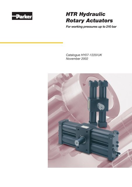
Catalogue HY07-1220/UKBenefits and General SpecificationsAdvantages of Parker'sRack and Pinion <strong>Rotary</strong> <strong>Actuators</strong>• Cost-effectiveness – especially above 90°, where linearactuators need increasingly intricate linkages to generaterotary motion.• Simplicity – a rotary actuator with a hollow, or female, shaftcan replace support bearings and pillow blocks, due to thehigh load capacity of the bearings.• Resistance to hostile environments – no extending/retractingsealing surfaces exposed to abrasive or corrosive substances.Special materials and coatings ensure long life in arduous usage.• Ease of maintenance – servicing of pistons and seals can becarried out with the actuator in place on the machine, subjectto access.• Leakage resistance – pressurized fluid is remote from theoutput side of the mechanism; piston seals are the onlydynamic seals subject to system pressure.• Long life – the rack/pinion/bearing assembly is packed withmolybdenum grease on assembly and does not come intocontact with hydraulic fluid.• Premium quality – every Parker rotary actuator is proof testedbefore shipping.<strong>Rotary</strong> <strong>Actuators</strong><strong>HTR</strong> SeriesGeneral Specification – VolumesSingleRack<strong>HTR</strong>.9<strong>HTR</strong>3.7<strong>HTR</strong>5<strong>HTR</strong>15<strong>HTR</strong>22<strong>HTR</strong>75<strong>HTR</strong>300ModelDoubleRack<strong>HTR</strong>1.8<strong>HTR</strong>7.5<strong>HTR</strong>10<strong>HTR</strong>30<strong>HTR</strong>45<strong>HTR</strong>150<strong>HTR</strong>600cm 3perdegreecm 3perradian90°RotationDisplacement – cm 3180°Rotation360°Rotation0.1 6 9 19 370.2 12 19 37 740.4 25 40 80 1590.9 51 79 159 3180.6 33 51 102 2051.1 65 102 205 4101.6 93 145 291 5823.2 185 291 582 11642.5 145 227 455 9105.1 290 455 910 18198.4 480 754 1508 301617 960 1508 3016 603232 1855 2913 5827 1165365 3707 5823 11645 23290General Specification – Torque Outputs, Pressure Ratings and WeightsSingleRack<strong>HTR</strong>.9<strong>HTR</strong>3.7<strong>HTR</strong>5<strong>HTR</strong>15<strong>HTR</strong>22<strong>HTR</strong>75<strong>HTR</strong>300ModelDoubleRack<strong>HTR</strong>1.8<strong>HTR</strong>7.5<strong>HTR</strong>10<strong>HTR</strong>30<strong>HTR</strong>45<strong>HTR</strong>150<strong>HTR</strong>600Continuous Duty 1 Intermittent Duty 2 Static Duty 3TorqueNmPressure<strong>bar</strong>TorqueNmPressure<strong>bar</strong>TorqueNmPressure<strong>bar</strong>80 160 100 <strong>210</strong> 100 <strong>210</strong>160 160 200 <strong>210</strong> 200 <strong>210</strong>260 125 390 190 420 <strong>210</strong>540 130 800 200 850 <strong>210</strong>330 120 495 180 565 <strong>210</strong>700 130 1000 190 1130 <strong>210</strong>960 115 1440 175 1700 <strong>210</strong>2000 120 3000 190 3400 <strong>210</strong>960 80 1440 115 1700 1402000 80 3000 120 3400 1404500 110 6750 165 8500 <strong>210</strong>9500 115 14200 170 17000 <strong>210</strong>13000 80 19500 120 34000 <strong>210</strong>28000 85 42000 130 68000 <strong>210</strong>90°RotationWeights – kg180°Rotation360°Rotation5 6 97 9 1113 14 1716 19 2417 18 2220 25 3025 27 3240 44 5327 30 3645 49 6190 100 120146 167 206345 382 414505 573 7091Continuous duty – >10 7 cycles2Intermittent duty –
Catalogue HY07-1220/UKShaft Options<strong>Rotary</strong> <strong>Actuators</strong><strong>HTR</strong> SeriesShaft OptionsKeyed and splined shaft designs are available for the <strong>HTR</strong>Series rotary actuators, in both male and female forms. Thestandard male, twin key shaft style is illustrated with othermajor dimensions on pages 6 and 7, while other shaft optionsare shown below. All the shaft options illustrated are shown inthe mid-stroke position. Custom designs, including doubleendedshafts, are available to special order – please contact thefactory for details.Male Splined ShaftMale Splined Shaft to DIN/ISO 14LMRModel<strong>HTR</strong>.9 & 1.8LMNa11PRNumberof splines33 22 22 18 5 6N<strong>HTR</strong>3.7 & 7.5<strong>HTR</strong>5 & 1048 32 28 23 6 666 44 42 36 7 8Mounting Faceof UnitP<strong>HTR</strong>15 & 30<strong>HTR</strong>22 & 4586 58 54 46 9 886 58 54 46 9 8<strong>HTR</strong>75 & 150115 76 72 62 12 8<strong>HTR</strong>300 & 600190 125 125 112 18 10Female Keyed ShaftFemale Keyed Shaft to DIN 6885DPinion &Keyway LengthB – KeywayModelAH7BP9C +0.4 D E0.4mm Radius<strong>HTR</strong>.9 & 1.8<strong>HTR</strong>3.7 & 7.516 5 20.6 74.6 25.422 6 27.6 98.4 38.1C<strong>HTR</strong>5 & 1032 10 38.6 98.4 44.5<strong>HTR</strong>15 & 3048 14 55.6 125.4 73.0E – Dia. Pinion Journal(All shaft styles)A – Bore<strong>HTR</strong>22 & 45<strong>HTR</strong>75 & 15048 14 55.6 125.4 73.072 20 81.8 188.9 95.2<strong>HTR</strong>300 & 600125 32 139.8 303.2 165.1Female Splined ShaftFemale Splined Shaft to DIN/ISO 14GKModelD F GHH10JH7KNumberof splines<strong>HTR</strong>.9 & 1.874.6 17 16 16 13 3.5 6FH<strong>HTR</strong>3.7 & 7.5<strong>HTR</strong>5 & 1098.4 23 22 22 18 5 698.4 29 29 28 23 6 6<strong>HTR</strong>15 & 30125.4 49 50 48 42 8 8DJ<strong>HTR</strong>22 & 45<strong>HTR</strong>75 & 150<strong>HTR</strong>300 & 600125.4 49 50 48 42 8 8188.9 73 76 72 62 12 8303.2 126 127 125 112 18 10All dimensions are in millimetres unless otherwise stated.Parker HannifinCylinder DivisionEurope
Catalogue HY07-1220/UKDimensions – <strong>HTR</strong>.9 to <strong>HTR</strong>10<strong>Rotary</strong> <strong>Actuators</strong><strong>HTR</strong> SeriesMAA/2LRSTPØ0.4mmRadiusFKØNOCVGRelief Valve<strong>HTR</strong>.9 to <strong>HTR</strong>5Single Rack ModelsEDE/2J (BothSides)UBB/2STMAA/2LRO2VPØ0.4mm RadiusFKØNCVGReliefValve<strong>HTR</strong>1.8 to <strong>HTR</strong>10Double Rack ModelsEDE/2J (BothSides)UBB/2Dimensions – with Face Mount and Male Keyed ShaftModelBoreRotationAmaxB C Cd Cs DE±0.13F±0.13Fd±0.13Fs±0.13G<strong>HTR</strong>.9<strong>HTR</strong>1.8<strong>HTR</strong>3.7<strong>HTR</strong>7.5<strong>HTR</strong>5<strong>HTR</strong>10<strong>HTR</strong>15<strong>HTR</strong>30<strong>HTR</strong>22<strong>HTR</strong>45<strong>HTR</strong>75<strong>HTR</strong>150<strong>HTR</strong>300<strong>HTR</strong>60022.238.150.863.5101.6152.490°180°360°90°180°360°90°180°360°90°180°360°90°180°360°90°180°360°90°180°360°19023733325733346428937256240654381641655382251470<strong>210</strong>737941111174976 92.5 – 89 70 60 – 30100 133.5 – 102 75 90 – 45100 152.5 – 102 75 125 – 62.5– 175– 50127 –178 150 –85206.5 – 170 –– 176– 50127 –178 150 –85213 – 170 –– 254– 115191 –216 165 –145327 – 290 –– 387– 125 195305 –403 330 –476.5 – 350 – 175All dimensions are in millimetres unless otherwise stated.Parker HannifinCylinder DivisionEurope
Catalogue HY07-1220/UKDimensions – <strong>HTR</strong>15 to <strong>HTR</strong>600<strong>Rotary</strong> <strong>Actuators</strong><strong>HTR</strong> SeriesMAA/2SVTPØ0.4mmRadiusGFsKØNLORCsRelief Valve<strong>HTR</strong>15 to <strong>HTR</strong>300Single Rack ModelsEDE/2J (BothSides)UBB/2STMAA/2LRO2VPØ0.4mm RadiusFdKØNCdGRelief Valve<strong>HTR</strong>30 to <strong>HTR</strong>600Double Rack ModelsEDE/2J (BothSides)UBB/2Dimensions – with Face Mount and Male Keyed ShaftModelBoreJK+0.00-0.02LMP9N O P R S TU(BSPP)V<strong>HTR</strong>.9<strong>HTR</strong>1.822.2M8x1.25x 1322 33 6 18.5 +0.0-0.1 25 25 45 10 13 G 1 /4 * 24<strong>HTR</strong>3.7<strong>HTR</strong>7.5<strong>HTR</strong>5<strong>HTR</strong>1038.1M10x1.5x 16M10x1.5x 1628 48 8 24 +0.0-0.2 38 38 64 13 18 G 1 /4 3544 66 12 39 +0.0-0.2 50 45 64 13 18 G 1 /4 41<strong>HTR</strong>15<strong>HTR</strong>3050.8M12x1.75x 1954 86 16 48 +0.0-0.2 60 73 76 16 18 G 1 /2 62<strong>HTR</strong>22<strong>HTR</strong>4563.5M12x1.75x 1954 86 16 48 +0.0-0.2 60 73 89 16 18 G 1 /2 62<strong>HTR</strong>75<strong>HTR</strong>150101.6M20x2.5x 3076 115 22 67 +0.0-0.2 85 95 127 26 21 G 3 /4 89<strong>HTR</strong>300<strong>HTR</strong>600152.4M30x3.5x 48125 190 32 114 +0.0-0.2 152 165 191 32 32 G1 130* G 1 /8 when combined with a stroke limiter – see page 11.All dimensions are in millimetres unless otherwise stated.Parker HannifinCylinder DivisionEurope
Catalogue HY07-1220/UKCushioning<strong>Rotary</strong> <strong>Actuators</strong><strong>HTR</strong> SeriesCushions andCushion Adjustment LocationCushioning is recommended as a means of controlling thedeceleration of masses. Machine life is extended as a resultof the reduced shock, permitting faster cycle times with lowerlevels of noise. Cushions are recommended for high kineticenergy applications and/or where the full rotation of theactuator is being used. They are available as an option on all<strong>HTR</strong> Series rotary actuators, for one or both rotations, and donot affect the actuator's envelope or mounting dimensions.For the <strong>HTR</strong> Series rotary actuator, the standard angle ofcushioning is 20° (0.349 rads).Each cushion is adjustable individually,allowing cushion performance to bematched to the application. The positions ofcushion adjusters, relative to port positions,are shown in the table – numbers relate tothe diagram of port positions on page 8.* Single rack models onlyNote: Where cushioning is required on double rack units,the High Performance Cushion option described on page 10should be specified.Floating Cushion BushCushion Adjustment NeedleCushion SpearPortPositionCushionPosition1 22 33 24 * 35 2Note that cushion performance will be affected by the use ofhigh water content fluids. Please consult the factory for details.The energy absorption capacity of the cushion decreaseswith drive pressure, which in normal circuits is the relief valvepressure.FormulaeFor a load that moves in the horizontal plane, only the kineticenergy need be considered. If the load is to move vertically,then the potential energy change of the load during cushioningmust also be taken into account. Both conditions are describedby the following equations. The resulting figure for energy to beabsorbed can then be applied to the graph of Cushion EnergyAbsorption Capacity, to identify a rotary actuator with adequatecushion capacity.Note: the graph of Cushion Energy Absorption Capacityshould only be used for initial sizing. For accurate sizing, pleasecontact the factory.For masses moving horizontally:1E = Jm ω 22For masses moving downwards:1E = Jm ω 2 + mgRθ2For masses moving upwards:E =1Jm ω 2 - mgRθ2Where:E = energy to be absorbed, JoulesJm = rotational mass moment of inertia, kgm 2ω = rotational velocity of load, rads/secm = mass of load, kgg = acceleration due to gravity, 9.81m/s 2R = radius of rotation, mθ = angle of cushioning, radians (0.349 rads = 20°)ExampleP = 100 <strong>bar</strong>m = 200 kgR = 0.2 mω = 6 rpmStandard cushions = 20° = 0.349 rads.E =1Jm ω 2 + mgRθ21E =(x 200 x 0.2] 2 x 6x2π 22 60 ])]E = 1.6 + 136.9E = 138.5 JoulesFrom the graph of Cushion Energy Absorption Capacity, itcan be seen that an <strong>HTR</strong>7.5 (double rack unit) is capable ofabsorbing this energy where the High Performance Cushionoption is specified. An <strong>HTR</strong>15 (single rack unit) is also capableof absorbing this energy.]+ (200 x 9.81 x 0.2 x 0.349)Parker HannifinCylinder DivisionEurope
Catalogue HY07-1220/UKCushioningHigh Performance CushionsThe High Performance cushion option can only be specified ondouble rack rotary actuators. Double rack rotary actuators canachieve very high torques, to move large masses which needto be decelerated at the end of travel. This cushion energy isabsorbed efficiently by the use of High Performance cushions.External piping ensures that during cushioning the maximumdeceleration torque is available. External interconnectingpipework for the High Performance cushion is not supplied withthe rotary actuator.OperationThe work ports of a standard directional valve are connecteddirectly to ports C-1 and C-2 of the rotary actuator, as shown.Port A-1 is connected directly to A-2, and B-1 is connecteddirectly to B-2. When pressure is applied directly to port C-1(clockwise shaft rotation), fluid is also directed through line Ato the other rack. Exhaust flow from B-1 and B-2 is directedthrough the cushion bush and cushion adjustment screwuntil the cushion spear closes off the main passage. The totalflow from both end caps is then directed across one cushionadjustment screw, equalizing back pressure and improvingcushion performance. Pressurizing C-2 and exhausting C-1reverses the operation.Notes1. Pipework between A-1 and A-2, and B-1 and B-2 shouldbe kept to a minimum to reduce the inertia of the fluid.Fluid flow should be less than 5m/s.2. Connection ports will have the same specification as theworking ports.<strong>Rotary</strong> <strong>Actuators</strong><strong>HTR</strong> SeriesCushion Energy Absorption Capacity– All Cushion OptionsEnergy Capacity (Joules)500030002000100070040030020010050403020<strong>HTR</strong>600 High Performance<strong>HTR</strong>150 High Performance<strong>HTR</strong>300<strong>HTR</strong>75<strong>HTR</strong>30 High Performance<strong>HTR</strong>45 High Performance<strong>HTR</strong>15, <strong>HTR</strong>22<strong>HTR</strong>7.5 High Performance<strong>HTR</strong>10 High Performance<strong>HTR</strong>3.7, <strong>HTR</strong>5<strong>HTR</strong>1.8 High Performance<strong>HTR</strong>.9A-2B-10 50 100 150C-1C-2Drive Pressure (<strong>bar</strong>)Note: Cushion performance may be affected by the addition of astroke limiter. Please consult the factory in critical applications.B-2A-1Port Positions<strong>Rotary</strong> actuators with High Performance Cushions differ fromstandard double rack units only in their port positions – allexternal dimensions of the units remain unaltered.Work Ports C-1 & C-2Port PositionCushion AdjusterPositionConnection PortsA-1, A-2, B-1, B-2Port Position1 2 32 3 13 2 15 2 310 Parker HannifinCylinder DivisionEurope
Catalogue HY07-1220/UKPiston Seals, Seal Kits and Stroke Limiters<strong>Rotary</strong> <strong>Actuators</strong><strong>HTR</strong> SeriesPiston Seals and Seal KitsThe Wear-Pak piston fitted as standard to all <strong>HTR</strong> Series rotaryactuators employs a polyurethane seal to contain hydraulicpressure, and a PTFE wear ring (not for <strong>HTR</strong>.9 or <strong>HTR</strong>1.8) toprevent metal-to-metal contact. For higher temperatures oruse with synthetic fluids, FPM seals should be specified for thepiston; for water glycol or high water content fluids, nitrile sealsare available.become over-pressurized. Any external leakage from thegear housing, therefore, is indicative of worn or damagedpiston seals and these should be examined and, if necessary,replaced, at the earliest opportunity.Note: it is essential that all hydraulic lines are thoroughlyflushed before connection to the rotary actuator.FiltrationEffective filtration is vital to the long life and satisfactoryperformance of a rotary actuator. If the piston seals of a rackand pinion rotary actuator are worn or damaged, fluid whichleaks past the piston will enter the gear housing.In the event of internal leakage into the gear housing, thepressure relief valve will ensure that the housing does notPTFE wear bandSteel pistonPolyurethane seal 1MaterialsSeal ClassSealWear RingStandard Polyurethane Filled PTFEV FPM Filled PTFEW Carboxilated Nitrile Filled PTFEFluid MediumGeneral purpose,petroleum-based fluidsHigh temperature and/orsynthetic fluidsWater glycol, high watercontent fluidsTemperatureRangeSeal Kit CodeFiltration-30° to +80° PSK<strong>HTR</strong>.9 2 ISO class 17/14-20° to +150° PSK<strong>HTR</strong>.9V 2cleanliness level0° to +80° PSK<strong>HTR</strong>.9W 21FPM seals also include a back-up washer.2The part numbers shown are for <strong>HTR</strong>.9 models. For other models,replace '.9' with the appropriate size. For example, an FPM seal kit foran <strong>HTR</strong>15 will be PSK<strong>HTR</strong>15V.Stroke LimitersFine control of the end of travel points of the rotary actuatorcan be obtained by specifying stroke limiters. These operateby reducing the maximum rotation of the actuator within presetlimits of either 5° or 30° in each direction. Adjustment withinthis range is infinitely variable and may be carried out by theuser. Several types of stroke limiter are available – the designillustrated is suitable for applications requiring infrequentadjustment.Stroke Limiters and Cushions5° stroke limiters may be combined with the cushioning devicesshown on page 10. 30° stroke limiters cannot be combinedwith cushions.The addition of stroke limiters requires an increase in buildlength. On double rack units with cushions, the cushion isfitted to the upper rack and the stroke limiter to the lower. Theincrease in build length, for both single and double rack units, isshown as dimension A in the table. Cushion performance maybe affected by the addition of a stroke limiter. Please consult thefactory in critical applications.B hexLock NutThread SealAModel<strong>HTR</strong>.9 & 1.8<strong>HTR</strong>3.7 & 7.5<strong>HTR</strong>5 & 10<strong>HTR</strong>15 & 30<strong>HTR</strong>22 & 45<strong>HTR</strong>75 & 150<strong>HTR</strong>300 & 600Adjustmentper Full TurnA max – Increased Build Length5° Limiter Without Cushion 5° Limiter With Cushion 30° Limiter Without CushionBHex Socket Screwin.4.0° 13 22 19 5/323.3° 16 29 29 1/42.5° 16 29 29 1/42.0° 22 46 41 3/82.0° 22 46 41 3/82.0° 65 95 90Square adjuster1.2° 90 154 N/AAll dimensions are in millimetres unless otherwise stated.11 Parker HannifinCylinder DivisionEurope
Catalogue HY07-1220/UKBearing Load Capacity<strong>Rotary</strong> <strong>Actuators</strong><strong>HTR</strong> SeriesBearing Load CapacitiesThe radial and thrust loads and overhung moments which canbe supported by each model of <strong>HTR</strong> rotary actuator at differentoperating pressures are shown in the table. These figuresshould be read in conjunction with the notes below.Notes1 Static bearing load capacities = dynamic values x 1.5ARadial Load RL2 Standard male shafts provide a 4:1 design factor. At theoperating conditions marked *, a smaller design factor isachieved and the values listed are 'bearing' momentcapacities. For higher capacities, larger shaft sizes areavailable – please consult the factory for details.Axial Load RTDynamic Bearing Load Capacities vs. Operating PressureModel<strong>HTR</strong>.9<strong>HTR</strong>1.8<strong>HTR</strong>3.7<strong>HTR</strong>7.5<strong>HTR</strong>5<strong>HTR</strong>10<strong>HTR</strong>15<strong>HTR</strong>30<strong>HTR</strong>22<strong>HTR</strong>45<strong>HTR</strong>75<strong>HTR</strong>150<strong>HTR</strong>300<strong>HTR</strong>600Radial Load kN RL per Bearing @ Thrust Load kN RT @ Overhung Moment kN.m RL x A @70 Bar 140 Bar <strong>210</strong> Bar 70 Bar 140 Bar <strong>210</strong> Bar 70 Bar 140 Bar <strong>210</strong> Bar16.6 15.2 13.9 12.0 11.5 11.1 0.28 0.25 0.2317.9 17.9 17.9 12.4 12.4 12.4 0.30 0.30 0.30 *26.3 22.2 18.3 16.1 15.0 13.9 0.71 0.59 0.4930.0 30.0 30.0 17.0 17.0 17.0 0.80 0.80 0.80 *34.1 30.2 26.3 18.9 17.9 17.0 0.87 0.77 0.6738.1 38.1 38.1 19.9 19.9 19.9 0.97 0.97 0.9761.4 54.4 47.4 54.7 52.6 50.4 2.85 2.53 2.2068.4 68.4 68.4 56.9 56.9 56.9 3.18 3.18 3.1857.9 47.4 – 53.7 50.4 – 2.69 2.20 –68.4 68.4 – 56.9 56.9 – 3.18 3.18 –72.7 44.8 16.8 73.6 62.6 51.5 7.37 4.54 1.70100.7 100.7 100.7 84.6 84.6 84.6 10.20 10.20 * 10.20 *129.3 66.4 3.4 107.2 87.7 68.3 19.53 10.02 0.52192.2 192.2 192.2 126.7 126.7 126.7 29.04 29.04 29.04 *12 Parker HannifinCylinder DivisionEurope
Catalogue HY07-1220/UKOrdering and Maintenance Information<strong>Rotary</strong> <strong>Actuators</strong><strong>HTR</strong> Series<strong>HTR</strong>CxxxxProductTypeModelCodeRotationCushionsMountingStyleShaftStylePortTypePortLocationSealsDesignSeriesOptionsCode Rotation Page090 90º 2180 180º 2360 360º 2Other – please specifyCode Bore Page.9 22.2 mm 61.8 22.2 mm 63.7 38.1 mm 67.5 38.1 mm 65 38.1 mm 610 38.1 mm 615 50.8 mm 630 50.8 mm 622 63.5 mm 645 63.5 mm 675 101.6mm 6150 101.6 mm 6300 152.4 mm 6600 152.4 mm 6Code Cushioning 1PageNone – standard 91 Clockwise rotation 5 92 Anti-clockwise rotation 5 93 Both directions 5 98 High Performance cushion 2 99 Special – add to 'Options' 9StrokeLimitersCode SealPage- Polyurethane – standard 11V FPM 11W Carboxilated nitrile 11Code LocationPage1-4 Side – specify positions 1-4 85 End 89 Special – add to 'Options' 8Code TypePage4 BSPP – standard 85 Metric – to DIN 3852/1 86 Metric – to ISO 6149/1 81 SAE straight thread 82 NPTF 89 Special – add to 'Options' 8Code StyleHPageMale, single ended, double key– standard 6G Female, double key 9K Male, double ended, double key 5L Female spline 5M Male spline, single ended 5N Male spline, double ended 5X Special – add to 'Options' 5Code Stroke limiter 1PageNone – standard 11A 0-5º Clockwise rotation 3 11B 0-5 º Anti-clockwise rotation 3 11C 0-5º Both rotations 3 11D 0-30º Clockwise rotation 4 11E 0-30 º Anti-clockwise rotation 3 11F 0-30º Both rotations 4 11X Special – add to 'Options' 11Code Mounting PageC Face – standard 6D Base 8T Pilot 8Code OptionPage1000 Standard actuator model code1111 Actuator model code with special options:eg: Air Bleeds – specify positions 1-4 8Position switches 13Feedback device 14Bronze rack bearing (<strong>HTR</strong>.9-10) 3Please attach full details of Special Options requiredMaintenance and Spare PartsFull instructions for the maintenance of <strong>HTR</strong> Series rotaryactuators, together with a complete list of the spares available,is contained in the <strong>HTR</strong> Series <strong>Rotary</strong> Actuator MaintenanceBulletin. Please ask for bulletin HY07-1220/M.Notes:1Viewed from shaft end2Double rack models only3Not available with end ports4Not available with end ports and cushions5Only available on single rack units15 Parker HannifinCylinder DivisionEurope