MMA Hydraulic Cylinders - Hidroser
MMA Hydraulic Cylinders - Hidroser
MMA Hydraulic Cylinders - Hidroser

You also want an ePaper? Increase the reach of your titles
YUMPU automatically turns print PDFs into web optimized ePapers that Google loves.
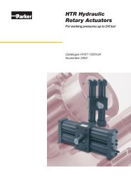
<strong>MMA</strong> <strong>Hydraulic</strong> <strong>Cylinders</strong>'Mill Type' roundline cylinders for workingpressures up to 250 bar
Catalogue HY07-1210/UKIntroductionContentsPageDesign Features and Benefits 3Seal Options 4Optional Features 5Servicing Features 5Mounting Information 5Cylinder Masses 5, 15Dimensions – Round Flange Mountings 6Dimensions – Pivot Mountings 7Dimensions – Trunnion and Foot Mountings 8-9Rod End Accessories 9Dimensions – Piston Rod Ends 10Push and Pull Forces 11Piston Rod Size Selection 12Long Stroke <strong>Cylinders</strong> 12Stop Tubes 13Stroke Factors 13Cushioning 14-15Ports 16Replacement Parts and Service 17-18How to Order <strong>Cylinders</strong> 19Port, Air Bleed and Cushion Adjustment Locations 19'Mill Type' <strong>Cylinders</strong><strong>MMA</strong> SeriesIntroductionThe heavy duty series <strong>MMA</strong> cylinder has been designed forservice in steel mills and in other arduous applications wherea rugged, dependable cylinder is required. In addition to thestandard cylinders featured in this catalogue, <strong>MMA</strong> cylinderscan be designed and manufactured to suit individual customerrequirements.Standard Specifications• Heavy Duty construction• Styles and dimensions to: CETOP RP73H, ISO 6022*,DIN 24 333, BS 6331 Pt. III, AFNOR NF E48-025, VW 39D 921• Rated pressure: 250 bar• Fatigue-free at the rated pressure• <strong>Hydraulic</strong> mineral oil – other fluids on request• Temperature range of standard seals: -20°C to +80°C• Construction: head & cap bolted to heavy steel flanges• Bore sizes: 50mm to 320mm• Piston rod diameters: 32mm to 220mm• Cushioning – optional at both ends• Air bleeds – optional at both ends• Tested in accordance with ISO 10100 : 2001* 140mm and 180mm bore cylinders do not conform to ISO 6022Parker Offers the Widest Range ofIndustrial <strong>Cylinders</strong>High Productivity – Low Cost of OwnershipParker Hannifin's Cylinder Division is the world's largestsupplier of hydraulic cylinders for industrial applications.Parker manufactures a vast range of standard and special tie rod,roundline and 'mill' type cylinders to suit all types of industrialcylinder applications. Our cylinders are available to ISO, DIN,NFPA, ANSI and JIC standards, with other certificationsavailable on request. All Parker hydraulic cylinders aredesigned to deliver long, efficient service with low maintenancerequirements, guaranteeing high productivity year after year.inPHormFor accurate sizing of <strong>MMA</strong> hydraulic cylinders, please contactyour nearest Parker Sales office and ask for the Europeancylinder inPHorm selection programme HY07-1260/Eur.About Parker HannifinParker Hannifin is the global leader in motion and controltechnologies, partnering with its customers to increase theirproductivity and profitability. The company employs morethan 61,000 people in 48 countries around the world, providingcustomers with technical excellence and first class customerservice.Visit us at www.parker.comWarningFAILURE OR IMPROPER SELECTION OR IMPROPER USE OF THE PRODUCTS AND/OR SYSTEMS DESCRIBED HEREIN OR RELATEDITEMS CAN CAUSE DEATH, PERSONAL INJURY AND PROPERTY DAMAGE.This document and other information from Parker Hannifin Corporation, its subsidiaries, sales offices and authorized distributors provideproduct or system options for further investigation by users having technical expertise. Before you select or use any product or system it isimportant that you analyse all aspects of your application and review the information concerning the product or system in the current productcatalogue. Due to the variety of operating conditions and applications for these products or systems, the user, through his own analysisand testing, is solely responsible for making the final selection of the products and systems and assuring that all performance and safetyrequirements of the application are met.The products described herein, including without limitation, product features, specifications, designs, availability and pricing, are subject tochange by Parker Hannifin Corporation and its subsidiaries at any time without notice.Offer of SalePlease contact you local Parker representative for a detailed offer of sale.2 Parker HannifinCylinder DivisionEurope
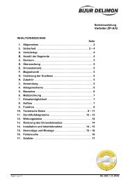
Catalogue HY07-1210/UKDesign Features and Benefits'Mill Type' <strong>Cylinders</strong><strong>MMA</strong> Series9827143610251 Piston RodManufactured from precision ground, high tensile carbon alloysteel, hard chrome plated and polished to 0.2mm max. Pistonrods up to 110mm in diameter are induction case hardened toRockwell C54 minimum before chrome plating. This providesa ‘dent resistant’ surface, resulting in improved seal life. Pistonrods of 125mm diameter and above can be case hardenedon request. All rod and piston assemblies are designed to befatigue free at full rated pressure.2 Head and Cap RetentionThe head and cap are bolted to heavy steel flanges, which areretained by threads at each end of the cylinder body.3 Cylinder BodyThe heavy wall steel tubing is honed to a high surface finish, tominimise internal friction and prolong seal life.4 & 5 Head & Cap EndsThese are machined from steel and located into the cylinderbody’s internal diameter for added strength and precisealignment. Both the head and cap are sealed by O-rings which,in turn, are protected by anti-extrusion rings.6 & 7 CushioningOptional cushions at the head and cap are progressive in action,providing controlled deceleration which reduces noise andshock loading, and prolongs machine life. The head end cushionis a self-centring sleeve, while the polished cap end spear is anintegral part of the piston rod. Needle valves are provided atboth ends of the cylinder for precise cushion adjustment, andare retained so that they cannot be inadvertently removed.Check valves at the head and cap ends of the cylinder minimizerestriction to the start of a stroke, permitting full power andfast cycle times. The head end check valve is incorporated intothe fully floating cushion sleeve, while the cap end employs afloating bronze cushion bush.8 Rod Gland and BearingsSeals are housed in a corrosion-resistant steel gland, featuringheavy duty polymer bearing rings to resist side loadings. Wideseparation of these rings reduces bearing stresses, maximisingthe service life of the bearing. The rod gland may be screwedor bolted. On bore sizes up to 100mm the rod gland is screwed(illustrated above). On larger bore sizes the rod gland is bolted.The polymer bearing rings, with the rod seals, are easilyreplaced on removal of the rod gland, and all components maybe serviced without further disassembly of the cylinder.9 & 10 Gland and Piston SealsA variety of gland and piston seal options is available, to suitdifferent applications, as shown on page 4. In addition, <strong>MMA</strong>cylinders can be designed and manufactured to suit individualcustomer requirements. Please contact the factory for details.The gland seals provide efficient retention of pressurized fluidwhile preventing the ingress of contaminants.Air BleedsAvailable as an option at both ends, air bleeds are recessed intothe head and cap and retained so they cannot be inadvertentlyremoved. The air bleed location, in relation to the supply portlocation, must be specified on the order – see page 19.Gland DrainsThe tendency of hydraulic fluid to adhere to the piston rod canresult in an accumulation of fluid in the cavity between the sealsunder certain operating conditions. This may occur with longstroke cylinders, where there is a constant back pressure as indifferential circuitry, or where the ratio of the extend speed tothe retract speed is greater than 2 to 1.Gland drains should be piped back to the fluid reservoir, whichshould be located below the level of the cylinder.3 Parker HannifinCylinder DivisionEurope
Catalogue HY07-1210/UKSeal Options'Mill Type' <strong>Cylinders</strong><strong>MMA</strong> SeriesGland and Piston Seal OptionsSee Illustrations, page 17Standard SealsThese are general purpose seals designed for a wide range ofapplications. They are suitable for use with Group 1 fluids andmay be used for piston speeds up to 0.5m/s.Standard gland seals employ a polyurethane lipseal and aPTFE stepped seal. The piston is fitted with a heavy duty filledpolymer seal, and heavy duty wear rings which prevent contactbetween the piston and cylinder bore, protecting the piston sealfrom contaminants.Low Friction OptionLow friction seals are suitable for applications where very lowfriction and an absence of stick-slip are important. They are notsuitable for holding loads in a fixed position. Low friction sealsare available for use with all fluid groups and are suitable forpiston speeds up to 1m/s.Low Friction gland seals comprise two low friction PTFEstepped seals and a heavy duty wiperseal, while the pistonsemploy a PTFE seal and PTFE wear rings.Chevron OptionChevron seals are designed for arduous applications, suchas steel mills. They are suitable for holding a load in position.Chevron seals are available for use with all fluid groups, atpiston speeds up to 0.5m/s.Chevron gland seals have a corrosion-resistant steel retainer,and a separate removable steel housing which retains the innerbearing rings. A heavy duty wiper seal prevents the ingress ofcontaminants. Chevron pistons feature a two-piece piston witha wide bearing ring mounted between chevron seals.Special SealsA range of seal options is available for the fluid groups listedbelow – see cylinder model numbers on page 19. Whererequired, special seals, in addition to those shown above, canalso be supplied. Please insert an S (Special) in the modelnumber and specify fluid medium when ordering.Group 6 Seal LifeSeal life is reduced with High Water Content Fluids (HFA) dueto the poor lubricity of the operating medium. Note that seal lifealso declines as pressure increases.Water ServiceSpecial modifications are available for high water contentfluids. These include a stainless steel piston rod, and plating ofinternal surfaces. When ordering, please specify the maximumoperating pressure or load/speed conditions, as the stainlesssteel rod is of lower tensile strength than the standard material.WarrantyParker Hannifin warrants cylinders modified for water or highwater content fluid service to be free of defects in materials orworkmanship, but cannot accept responsibility for prematurefailure caused by excessive wear resulting from lack of lubricity,or where failure is caused by corrosion, electrolysis or mineraldeposits within the cylinder.FiltrationFluid cleanliness should be in accordance with ISO 4406. Thequality of filters should be in accordance with the appropriateISO standards.The rating of the filter media depends on the system componentsand the application. The minimum required should be class 19/15to ISO 4406, which equates to 25µ (ß10≥75) to ISO 4572.Load Holding OptionSuitable for applications where loads are required to be heldin position, the Load Holding option combines Standard glandseals, which have lower friction than the chevron equivalent, withchevron piston seals. They are suitable for use with Group 1 fluidsand may be used for piston speeds up to 0.5m/s.Seals and Fluid DataFluidGroupSeal Materials – a combination of: Fluid Medium to ISO 6743/4-1982Piston &Gland TypeTemperature Range1Nitrile (NBR), PTFE,enhanced polyurethane (AU)Mineral Oil HH, HL, HLP, HLP-D, HM, HV, MIL-H-5606 oil,air, nitrogenAll-20°C to +80°C2 Nitrile (NBR), PTFE Water glycol (HFC)Chevron andLow Friction-20°C to +60°C5 Fluorocarbon elastomer (FPM), PTFEFire resistant fluids based on phosphate esters (HFD-R)Also suitable for hydraulic oil at high temperatures or in hotenvironments. Not suitable for use with Skydrol.See fluid manufacturer's recommendations.Chevron andLow Friction-20°C to +150°C6Various compounds including nitrile,enhanced polyurethane, fluorocarbonelastomers and PTFEWaterOil in water emulsion 95/5 (HFA)7 Water in oil emulsion 60/40 (HFB)Chevron andLow FrictionChevron andLow Friction+5°C to +55°C+5°C to +60°C4 Parker HannifinCylinder DivisionEurope
Catalogue HY07-1210/UKRound Flange Mountings'Mill Type' <strong>Cylinders</strong><strong>MMA</strong> SeriesEE122 1 /2°YZB + strokePJ + stroke2FC p.c.d.4BDmax.Style MF3Head Circular FlangeØFBF3UCVDWCAccurate location of 'B' provided as standard on model MF3 only.EE122 1 /2°YPJ + stroke2FC p.c.d.4BADmax.Style MF4Cap Circular FlangeØFB3UCZP + strokeFDimensions – MF3 and MF4 See also Rod End Dimensions, page 10BoreØ506380100125RodNo.1212121212140 1 1216012180 1 12200250320121212MMRodØ3236404550566370809090100100110110125125140160180200220B f8&BA H8Dmax.EE(BSPP)1140mm and 180mm bore cylinders do not conform to ISO 6022.F FB FC UCVDmin.WCYMin.StrokePJ+ Stroke63 108 G 1 /2 25 13.5 132 155 4 22 98 20 120 244 26575 124 G 3 /4 28 13.5 150 175 4 25 112 30 133 274 29890 148 G 3 /4 32 17.5 180 210 4 28 120 20 155 305 332110 175 G1 36 22 212 250 5 32 134 25 171 340 371132 208 G1 40 22 250 290 5 36 153 50 205 396 430145 255 G1 1 /4 40 26 300 340 5 36 181 50 208 430 465160 270 G1 1 /4 45 26 315 360 5 40 185 50 235 467 505185 315 G1 1 /4 50 33 365 420 5 45 205 20 250 505 550200 330 G1 1 /4 56 33 385 440 5 45 220 20 278 550 596250 412 G1 1 /2 63 39 475 540 8 50 260 20 325 652 703320 510 G2 80 45 600 675 8 56 310 20 350 764 830ZBmax.ZPAll dimensions are in millimetres unless otherwise stated.6 Parker HannifinCylinder DivisionEurope
Catalogue HY07-1210/UKPivot Mountings'Mill Type' <strong>Cylinders</strong><strong>MMA</strong> SeriesEED max.1YPJ + strokeCD24MRStyle MP3Cap Fixed Eye3EWBWXC + strokeLLXEED max.1YPJ + strokeCX4°24MS4°Style MP5Cap Fixed Eyewith Spherical Bearing3EXBXXO + strokeLTLXDimensions – MP3 and MP5 See also Rod End Dimensions, page 10BoreØ506380100125RodNo.1212121212140 1 1216012180 1 12200250320121212MMRodØ3236404550566370809090100100110110125125140160180200220BW&BXCD H9&CX H7Dmax.1140mm and 180mm bore cylinders do not conform to ISO 6022.EE(BSPP)EW h12&EX h12L<LXMR&MSYMin.StrokePJ+ StrokeXC & XO27 32 108 G 1 /2 32 61 38 35 98 20 120 30535 40 124 G 3 /4 40 74 50 50 112 30 133 34840 50 148 G 3 /4 50 90 61.5 61.5 120 20 155 39552 63 175 G1 63 102 71 66 134 25 171 44260 80 208 G1 80 124 90 90 153 50 205 52065 90 255 G1 1 /4 90 150 113 113 181 50 208 58084 100 270 G1 1 /4 100 150 112 112 185 50 235 61788 110 315 G1 1 /4 110 185 129 118 205 20 250 690102 125 330 G1 1 /4 125 206 145 131 220 20 278 756130 160 412 G1 1 /2 160 251 178 163 260 20 325 903162 200 510 G2 200 316 230 209 310 20 350 1080All dimensions are in millimetres unless otherwise stated.7 Parker HannifinCylinder DivisionEurope
Catalogue HY07-1210/UKTrunnion and Foot Mountings'Mill Type' <strong>Cylinders</strong><strong>MMA</strong> SeriesEE1YPJ + strokeBDR3TD24UVmax.Dmax.Style MT4Intermediate TrunnionTLNote:3TMTLXV Dimension to be specified by customer. Where minimum dimension isunacceptable, please consult factory.XVZB + strokeEE1YPJ + strokeSD24Dmax.2mmLHStyle MS2Foot Mounting(Not to ISO 6022)ØSB 3TSNote:USSTThe MS2 mounting should only be used where the stroke is at least half of the borediameter or where the cylinder operates below 160 bar.XSSESCZB + strokeSCSS + strokeSEDimensions – MT4 See also Rod End Dimensions, page 10BoreØ506380100125RodNo.1212121212140 1 1216012180 1 12200250320121212MMRodØ3236404550566370809090100100110110125125140160180200220BDDmax.EE(BSPP)TD f8 TL TM h13 UVmax.XVmin.YMin.StrokePJ+ StrokeXV max.38 108 G 1 /2 32 25 112 108 187 98 55 120 132 24448 124 G 3 /4 40 32 125 124 212 112 75 133 137 27458 148 G 3 /4 50 40 150 148 245 120 90 155 155 30573 175 G1 63 50 180 175 280 134 120 171 160 34088 208 G1 80 63 224 218 340 153 160 205 180 39698 255 G1 1 /4 90 70 265 260 380 181 180 208 200 430108 270 G1 1 /4 100 80 280 280 400 185 180 235 220 467118 315 G1 1 /4 110 90 320 315 410 205 170 250 240 505133 330 G1 1 /4 125 100 335 330 450 220 190 278 260 550180 412 G1 1 /2 160 125 425 412 540 260 240 325 300 652220 510 G2 200 160 530 510 625 310 300 350 325 764ZBmax.1140mm and 180mm bore cylinders do not conform to ISO 6022.All dimensions are in millimetres unless otherwise stated.8 Parker HannifinCylinder DivisionEurope
Catalogue HY07-1210/UKFoot Mountings and Accessories'Mill Type' <strong>Cylinders</strong><strong>MMA</strong> SeriesDimensions – MS2 See also Rod End Dimensions, page 10BoreØRodNo.50126312801210012125121140 1 2160121180 1 2200122501232012MMRodØ3236404550566370809090100100110110125125140160180200220Dmax.EE(BSPP)LH h10 SB H13 SC SD SE ST TS US XS YMin.Stroke+ Stroke108 G 1 /2 60 11 20.5 2 18 15.5 32 135 160 130.0 98 0 120 55 244124 G 3 /4 68 13.5 24.5 2 20 17.5 37 155 185 147.5 112 20 133 55 274148 G 3 /4 80 17.5 22.5 26 22.5 42 185 225 170.5 120 35 155 55 305175 G1 95 22 27.5 33 27.5 52 220 265 192.5 134 55 171 55 340208 G1 115 26 30.0 40 30.0 62 270 325 230.0 153 65 205 60 396255 G1 1 /4 135 30 35.5 48 35.5 77 325 390 254.5 181 80 208 61 430270 G1 1 /4 145 33 37.5 48 37.5 77 340 405 265.5 185 80 235 79 467315 G1 1 /4 165 40 42.5 60 42.5 87 390 465 287.5 205 70 250 85 505330 G1 1 /4 170 40 47.0 2 60 45.0 87 405 480 315.0 220 60 278 90 550412 G1 1 /2 215 52 52.0 2 76 50.0 112 520 620 360.0 260 60 325 120 652510 G2 260 62 62.0 2 110 60.0 152 620 740 425.0 310 80 350 120 764PJSSZBmax.1140mm and 180mm bore cylinders do not conform to ISO 60222Mounting holes offset from centre lineRod End AccessoriesC max.EFENC max.EREMBXLFCN4°LECKCHAXmin.CAAWmin.KKKKRod Eye with Spherical Bearing – ISO 6982 Rod Eye with Plain Bearing – ISO 6981DimensionsBoreØKK50 M27x263 M33x280 M42x2100 M48x2125 M64x3140 M72x3160 M80x3180 M90x3200 M100x3250 M125x4320 M160x4Part No. – Rod Eye with:SphericalBearingPlainBearing145241 148731145242 148732145243 148733145244 148734145245 148735148723 148736148724 148737148725 148738148726 148739148727 148740148728 148741All dimensions are in millimetres unless otherwise stated.bAX&AWmin.CN H7&CK H9EN h12&EM h12CH&CALF&LECmax.EF&ERBX9 Parker HannifinCylinder DivisionEuropebTorqueLoadNm37 32 32 80 32 76 40 27 38 32 1.246 40 40 97 41 97 50 32 47 32 2.157 50 50 120 50 118 63 40 58 64 4.464 63 63 140 62 142 71 52 70 80 7.6Masskg86 80 80 180 78 180 90 66 90 195 14.591 90 90 195 85 185 101 72 100 195 1796 100 100 210 98 224 112 84 110 385 28106 110 110 235 105 235 129 88 125 385 32113 125 125 260 120 290 160 103 135 385 43126 160 160 310 150 346 200 130 165 660 80161 200 200 390 195 460 250 162 215 1350 165b
Catalogue HY07-1210/UKPiston Rod End Data'Mill Type' <strong>Cylinders</strong><strong>MMA</strong> SeriesRod End Style 4 Rod End Style 9D Wrench FlatsD Wrench FlatsNA KKMMNAKF<strong>MMA</strong>CWCWAFPiston Rod End Styles<strong>MMA</strong> cylinders are available with standard metric male andfemale rod ends to ISO 4395. They can also be supplied withother rod end threads, eg: ISO metric coarse, Unified, BritishStandard etc., or to the customer's special requirements.Wrench FlatsPiston rods up to and including 90mm in diameter are suppliedwith the wrench flats D shown in the table below. Rods above90mm in diameter feature four drilled holes to accept a pinwrench.Style 4 denotes a standard male thread. Style 9 denotes afemale thread, and is available only with the No.2 rod. Ordersfor non-standard rod ends, designated Style 3, should includedimensioned sketches and descriptions, showing dimensionsKK or KF, A or AF, and the thread form required.Rod End Dimensions See also Cylinder Dimensions, pages 6-9BoreØRodNo.MMRodØA & AF C D NAKKStyle 4KFStyle 9W5012323636 1528323135M27x2–M27x2226312404545 1834363843M33x2–M33x2258012505656 2043464854M42x2–M42x22810012637063 2353606067M48x2–M48x23212512809085 2765757787M64x3–M64x336.5140129010090 2775–8796M72x3–M72x336.51601210011095 31––96106M80x3–M80x340.518012110125105 36––106121M90x3–M90x345.520012125140112 36––121136M100x3–M100x345.525012160180125 38––155175M125x4–M125x450.532012200220160 44––195214M160x4–M160x456.5All dimensions are in millimetres unless otherwise stated.10 Parker HannifinCylinder DivisionEurope
Catalogue HY07-1210/UKPush and Pull ForcesCalculation of Cylinder DiameterIf the piston rod is in compression, use the ‘Push Force’ table.1. Identify the operating pressure closest to that required.2. In the same column, identify the force required to move theload (always rounding up).3. In the same row, look along to the cylinder bore required.If the cylinder envelope dimensions are too large, increase theoperating pressure, if possible, and repeat the exercise.Push ForceBoreØCylinderBore Areamm 250 196463 311780 5026100 7854125 12272140 15386160 20106180 25434200 31416250 49087320 8042550barCylinder Push Force in kN100bar150bar200barinPHormFor more comprehensive information on the calculation ofcylinder bore size required, please refer to the Europeancylinder inPHorm selection programme HY07-1260/Eur.250bar10 20 30 40 5015 31 46 63 7925 51 76 102 12840 80 120 160 20062 125 187 250 31277 154 231 308 385102 205 307 410 512127 254 381 508 635160 320 480 640 801250 500 750 1000 1250410 820 1230 1640 2050'Mill Type' <strong>Cylinders</strong><strong>MMA</strong> SeriesIf the piston rod is in tension, use the ‘Deduction for Pull Force’table. To determine the pull force:1. Follow the procedure for ‘Push’ applications, as described.2. Using the ‘Deduction for Pull Force’ table below, establishthe force indicated according to the rod diameter andpressure selected.3. Deduct this from the original ‘Push’ force. The resultingfigure is the net force available to move the load.If this force is not large enough, repeat the process again butincrease the system operating pressure or cylinder diameter ifpossible. If in doubt, please contact our design engineers.Deduction for Pull ForcePistonRodØPistonRod Areamm 232 80436 101840 125745 159050 196456 246363 338670 384880 502790 6362100 7855110 9503125 12274140 15394160 20109180 25447200 31420220 38013Reduction in Cylinder Push Force in kNdue to Area of Piston rod50bar100bar150bar200bar250bar4 8 12 16 205 10 15 20 256 12 19 24 318 16 24 32 4010 19 29 38 4912 25 37 50 6217 34 51 68 8519 39 58 78 9825 50 76 100 12632 64 97 129 16239 79 118 158 19648 96 145 193 24261 123 184 246 30778 156 235 313 392100 201 301 402 503129 259 389 518 648157 314 471 628 785198 387 581 775 969All dimensions are in millimetres unless otherwise stated.11 Parker HannifinCylinder DivisionEurope
Catalogue HY07-1210/UKPiston RodsPiston Rod Size Selection1. Determine the type of cylinder mounting style and rod endconnection to be used. Consult the Stroke Factor Selectiontable on page 13 and determine which factor corresponds tothe application.2. Using this stroke factor, determine the ‘basic length’ from theequation:Basic Length = Actual (net) Stroke x Stroke Factor'Mill Type' <strong>Cylinders</strong><strong>MMA</strong> SeriesLong Stroke <strong>Cylinders</strong>When considering the use of long stroke cylinders, the pistonrod should be of sufficient diameter to provide the necessarycolumn strength.For tension (pull) loads, the rod size is selected by specifyingstandard cylinders with standard rod diameters, and usingthem at or below the rated pressure.For long stroke cylinders under compressive loads, the use of astop tube should be considered, to reduce bearing stress.(The Piston Rod Selection Chart, below, applies to pistonrods with standard rod extensions beyond the face of thegland retainer. For rod extensions greater than standard, addthe increase to the stroke to arrive at the ‘basic length’.)Cushion SleeveStop Tube3. Find the load imposed for the thrust application by multiplyingthe full bore area of the cylinder by the system pressure, or byreferring to the Push and Pull Force charts on page 11.4. Using the Piston Rod Selection Chart, below, look along thevalues for ‘basic length’ and ‘thrust’ as found in 2. and 3.above, and note the point of intersection.The correct piston rod size is read from the diagonally curvedline labelled ‘Rod Diameter’ above the point of intersection.Piston Rod Selection ChartRod Diameter (mm)12 Parker HannifinCylinder DivisionEurope
Catalogue HY07-1210/UKStroke FactorsStop TubesThe Piston Rod Selection Chart indicates where the use of astop tube should be considered. The required length of stoptube, where necessary, is read from the vertical columns on theright of the chart, by following the horizontal band within whichthe point of intersection lies. Note that stop tube requirementsdiffer for fixed and pivot mounted cylinders.If the required length of stop tube is in the shaded regionmarked 'consult factory', please submit the followinginformation:1. Cylinder mounting style.2. Rod end connection and method of guiding load.3. Bore and stroke required, and length of rod extension(Dimension 'W') if greater than standard.'Mill Type' <strong>Cylinders</strong><strong>MMA</strong> Series4. Mounting position of cylinder. If at an angle or vertical,specify the direction of the piston rod.5. Operating pressure of the cylinder if limited to less thanthe standard pressure for the cylinder selected.When specifying a cylinder with a stop tube, please insertan 'S' (Special) and the net stroke of the cylinder in the ordercode, and state the length of the stop tube. Note that net strokeis equal to the gross stroke of the cylinder less the lengthof the stop tube. The gross stroke determines the envelopedimensions of the cylinder.inPHormFor accurate sizing, please refer to the European cylinderinPHorm selection programme HY07-1260/Eur.Stroke Factor SelectionRod EndConnectionStyleType of MountingStrokeFactorFixed and rigidlyguidedMF3MS20.5Pivoted andrigidly guidedMF3MS20.7Fixed and rigidlyguidedMF41.0Pivoted andrigidly guidedMF4MT41.5Supported but notrigidly guidedMF3MS22.0Pivoted andrigidly guidedMP3MP52.0Supported but notrigidly guidedMF44.0Supported but notrigidly guidedMP3MP54.013 Parker HannifinCylinder DivisionEurope
Catalogue HY07-1210/UKCushioningAn Introduction to CushioningCushioning is recommended as a means of controlling thedeceleration of masses, or for applications where pistonspeeds are in excess of 0.1m/s and the piston will make a fullstroke. Cushioning extends cylinder life and reducesundesirable noise and hydraulic shock.Built-in deceleration devices or 'cushions' are optional andcan be supplied at the head and cap ends of the cylinderwithout affecting its envelope or mounting dimensions.Cushions are adjustable via recessed needle valves.Standard CushioningIdeal cushion performance shows an almost uniform absorptionof energy along the cushion's length. Where specified, <strong>MMA</strong>cylinders use specially profiled cushions, giving a performancewhich comes close to the ideal in the majority of applications.The head and cap cushion performance for each bore size isillustrated on the charts on page 15.Alternative Forms of CushioningSpecial designs can be produced to suit applications wherethe energy to be absorbed exceeds the performance of thestandard cushion. Please consult the factory for details.Cushion LengthAll <strong>MMA</strong> cylinder cushions incorporate the longest cushionsleeve and spear that can be provided in the standard envelopewithout decreasing the rod bearing and piston bearing lengths –see table of cushion lengths on page 15.Cushion CalculationsThe charts on page 15 show the energy absorption capacityfor each bore and rod combination at the head (annulus) andthe cap (full bore) ends of the cylinder. The charts are validfor piston velocities in the range of 0.1–0.3m/s. For velocitiesbetween 0.3m/s–0.5m/s, the energy values from the chartsshould be reduced by 25%. For velocities of less than 0.1m/swhere large masses are involved, and for velocities greaterthan 0.5m/s, a special cushion profile may be required. Pleaseconsult the factory.The cushion capacity of the head end is less than that of the cap,owing to the pressure intensification effect across the piston.The energy absorption capacity of the cushion decreases withdrive pressure, which in normal circuits is the relief valve setting.inPHormCushioning requirements can be calculated automaticallyfor individual cylinder/load combinations using the Europeancylinder inPHorm selection programme HY07-1260/Eur.'Mill Type' <strong>Cylinders</strong><strong>MMA</strong> SeriesFormulaeCushioning calculations are based on the formula: E = ½mv 2 forhorizontal applications. For inclined or vertically downward orupward applications, this is modified to:E = ½mv 2 + mgl x 10 -3 x sinα– for inclined or vertically downward direction of mass;E = ½mv 2 – mgl x 10 -3 x sinα– for inclined or vertically upward direction of mass.Where:E = energy absorbed in Joulesg = acceleration due to gravity = 9.81m/s 2v = velocity in metres/secondl = length of cushion in millimetres (see page 15)m = mass of load in kilogrammes (including piston and rod,see page 15)α = angle to horizontal in degreesp = pressure in barExampleThe following example shows how to calculate the energydeveloped by masses moving in a straight line. For non-linearmotion, other calculations are required; pleaseconsult the factory. Theexample assumes that thebore and rod diametersare already appropriatefor the application. Theeffects of friction on thecylinder and load havebeen ignored.Selected bore/rod = 80/50mm (No.1 rod)Cushioning at the cap endPressure = 150 barMass = 7710 kgVelocity = 0.4m/sα =45 oSinα = 0.7Cushion length = 45mmE =½mv 2 + mgl x 10 -3 x sinαE = 7710 x 0.4 2 + 7710 x 9.81 x 45 x 0.72 10 3E = 617 + 2383 = 3000 JoulesNote: as velocity is greater than 0.3m/s, the energy absorptionfigures obtained from the charts on page 15 should be reducedby 25% – see Cushion Calculations, opposite. Comparison withthe cushioning chart curve for this cylinder shows an energycapacity for the cap end cushion of 5100 Joules. Reducingthis by 25% gives a capacity of 3825 Joules, so the standardcushion can safely decelerate the 3000 Joules in this example.Where cushion performance figures are critical, our engineerscan run a computer simulation to determine accurate cushionperformance – please contact the factory for details.14 Parker HannifinCylinder DivisionEurope
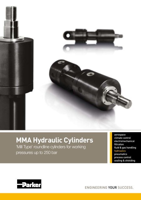
Catalogue HY07-1210/UKCushioningCushion Energy Absorption DataThe cushion energy absorption capacity data shown below arebased on the maximum fatigue-free pressures developed in thecylinder tube. If working life cycle applications of less than 10 6'Mill Type' <strong>Cylinders</strong><strong>MMA</strong> Seriescycles are envisaged, then greater energy absorption figurescan be applied. Please consult the factory if further informationis required.Head End, No.1 RodHead End, No.2 Rod10000001000000320/200100000320/220100000250/160200/125180/110160/100140/90125/80100/6380/5063/4050/32100001000Energy Capacity (Joules)250/180200/140180/125160/110140/100125/90100/7080/5663/4550/36100001000Energy Capacity (Joules)1001000 40 80 120 160 200 240Drive Pressure (bar)100 40 80 120 160 200 240Drive Pressure (bar)10Cap End, No.1 and No.2 Rods3202502001801601401251008063500 40 80 120 160 200 240Drive Pressure (bar)100000010000010000100010010Energy Capacity (Joules)Cushion Length, Piston & Rod MassBoreØ506380100125140160180200250320RodNo.1212121212121212121212RodØ3236404550566370809090100100110110125125140160180200220CushionLength30404555606065656590100Piston & RodZero strokekg2.02.33.44.05.86.710.712.120.723.828.031.040.144.654.062.076.286.0131.8150.2250.2279.7All dimensions are in millimetres unless otherwise stated.Rod per10mm Strokekg0.060.080.100.120.150.190.240.300.390.500.500.620.620.750.750.960.961.2310582.002.462.9815 Parker HannifinCylinder DivisionEurope
Catalogue HY07-1210/UKPortsPort Size and Piston SpeedFluid velocity in connecting lines should be limited to 5m/s tominimise fluid turbulence, pressure loss and 'water hammer'effects. The tables below show piston speeds for standard andoversize ports and connecting lines where the velocity of fluid is5m/s. If the desired piston speed results in a fluid flow in excessof 5m/s in connecting lines, larger lines with two ports per capshould be considered. Parker recommends that a flow rate of12m/s in connecting lines should not be exceeded.BoreØ506380100125140160180200250320PortSize(BSPP)Standard Cylinder PortBore ofConnectingLinesCap End Flowin l/min at5m/s 1PistonSpeedm/sG 1 /2 13 40 0.34G 3 /4 15 53 0.28G 3 /4 15 53 0.18G1 19 85 0.18G1 19 85 0.12G1 1 /4 22 114 0.12G1 1 /4 22 114 0.10G1 1 /4 22 114 0.08G1 1 /4 22 114 0.06G1 1 /2 28 185 0.06G2 38 340 0.07'Mill Type' <strong>Cylinders</strong><strong>MMA</strong> SeriesPort TypesIn addition to the standard and oversize BSPP ports, metricthreaded ports to DIN 3852 Pt. 1 and ISO 6149, and flangeports to ISO 6162 can also be supplied – see tables below.The ISO 6149 port incorporates a raised ring in the spot face foridentification. Other flange port styles are available on request.BoreØ506380100125140160180200250320BSPPStandard PortMetricDNFlangeBSPPOversize PortMetricDNFlangeG 1 /2 M22x1.5 13 G 3 /4 M27x2 *G 3 /4 M27x2 13 G1 M33x2 *G 3 /4 M27x2 13 G1 M33x2 19G1 M33x2 19 G1 1 /4 M42x2 25G1 M33x2 19 G1 1 /4 M42x2 25G1 1 /4 M42x2 25 G1 1 /2 M48x2 32G1 1 /4 M42x2 25 G1 1 /2 M48x2 32G1 1 /4 M42x2 25 G1 1 /2 M48x2 32G1 1 /4 M42x2 25 G1 1 /2 M48x2 32G1 1 /2 M48x2** 32 G2 M60x2 38G2 M60x2 32 – – 38* Consult factory** An M50 thread to DIN 24 333 can be supplied if required.Flange Port SizesBoreØ506380100125140160180200250320PortSize(BSPP)1This refers to fluid velocity in connecting lines, not piston velocityFlange Port SizesEAOversize Cylinder PortBore ofConnectingLinesEDCap End Flowin l/min at5m/s 1FFEBPistonSpeedm/sG 3 /4 14 53 0.45G1 19 85 0.46G1 19 85 0.28G1 1 /4 22 114 0.24G1 1 /4 22 114 0.16G1 1 /2 28 185 0.20G1 1 /2 28 185 0.15G1 1 /2 28 185 0.12G1 1 /2 28 185 0.10G2 38 340 0.12– – – –ABoreØ506380100125140160180200250320BoreØ506380100125140160180200250320Standard Flange PortDNFlange 1 A EA EB ED13 4713 5513 6819 8019 9725 12125 12925 15225 16032 20132 250FFØ17.5 38.1 M8x1.25 1322.2 47.6 M10x1.5 1926.2 52.4 M10x1.5 2530.2 58.7 M12x1.75 2 32Oversize Flange PortDNFlange 1 A EA EB ED– – – – – –– – – – – –FFØ19 66 22.2 47.6 M10x1.5 1925 7925 9732 12032 12832 15132 15926.2 52.4 M10x1.5 2530.2 58.7 M12x1.75 2 3238 3 197 3 36.5 3 79.3 3 M16x2 3 38 338 3 248 3All dimensions are in millimetres unless otherwise stated.125 bar to 350 bar series2M10x1.5 to ISO 6162 (1994) optional3400 bar series16 Parker HannifinCylinder DivisionEurope
Catalogue HY07-1210/UKReplacement Parts and Service'Mill Type' <strong>Cylinders</strong><strong>MMA</strong> SeriesService KitsService kits for <strong>MMA</strong> cylinders simplify the maintenanceprocess and are supplied with full instructions. When orderingservice kits, please refer to the identification plate on thecylinder body, and supply the following information:Serial Number - Bore - Stroke - Model Number - Fluid TypeKey to Part Numbers1 Head7 Cap14a Standard and Low Friction gland14b Chevron gland15 Cylinder tube17 Piston17a Chevron piston – head end17b Chevron piston – cap end18 Cushion sleeve19 Front/rear flange23 Head/cap securing screw26 O-ring (cylinder body)27 Gland retainer(secured by screws or threaded)125 Standard piston seal126 Energising ring for Standard seal 125127 Wear ring for Standard piston131 Low Friction piston seal132 Energising ring for Low Friction piston seal 131133 Wear ring for Low Friction piston134 O-ring back up washer (gland/head)136 Gland securing screw137 Chevron rod seal assembly138 Back up washer – Chevron rod seal assembly139a Wear ring for Chevron gland139b Wear rings for Chevron gland140a Wear ring for Standard gland140b Wear rings for Standard gland141a Wear ring for Low Friction gland141b Wear rings for Low Friction gland142 Chevron piston bearing ring143 Chevron piston seal assembly2634/35/36/3717737231815477469a261970a402745169a471940140a41124134 45123 140b14a46126125127175514b13470aStandard Gland & SealsStandard Piston124134 45131133 13234 Piston rod – single rod, no cushion35 Piston rod – single rod, cushion at head end36 Piston rod – single rod, cushion at cap end37 Piston rod – single rod, cushion at both ends40 Gland wiperseal41 Lipseal45 O-ring (gland/head)46 O-ring, piston/rod (2 off – chevron piston)47 O-ring (cylinder body)55 Piston locking pin69a Cushion needle valve cartridge sealing washer70a Cushion needle valve cartridge73 Floating cushion bush74 Cushion bush retaining ring123 Stepseal124 Pre-load ring for stepseal 1234014a141a123 141bLow Friction Gland & Seals134 451362714b40 138 137139a139bChevron Gland & Seals17a4646Low Friction Piston142143Chevron Piston175517b5517 Parker HannifinCylinder DivisionEurope
Catalogue HY07-1210/UKReplacement Parts and ServiceContents and Part Numbers of Service KitsGland Service Cartridge Kit Contains items 14a, 40, 41, 45,123, 124, 134, 140a, and two of 140b.Chevron Gland Service Cartridge Kit Contains items 14b,40, 45, 134, 137, 138, 139a, and two of 139b.Low Friction Gland Service Cartridge Kit Contains items14a, 40, 45, 134, 141a, and two each of 123, 124, 141b.Gland Service Kit Contains items 40, 41, 45, 123, 124, 134,140a, and two of 140b.Chevron Gland Service Kit Contains items 40, 45, 134, 137,138, 139a, and two of 139b.Low Friction Gland Service Kit Contains items 40, 45, 134,141a, and two each of 123, 124, 141b.Piston Service Kit, Standard Seals Contains items 125, 126,and two of 26, 47 and 127.Piston Service Kit, Chevron Seals Contains items 55, 142,and two each of 26, 46, 47 and 143.Piston Service Kit, Low Friction Seals Contains items 131,132, and two of 26, 47 and 133.Optional Seal Groups – OrderingThe order codes listed for Chevron and Low Friction servicekits contain standard, Group 1 seals. To order kits with otherclasses of seals, replace the last digit of the part number shown'Mill Type' <strong>Cylinders</strong><strong>MMA</strong> Serieswith the number of the service group required.Eg: RGF210<strong>MMA</strong>0701, containing a Group 1 seal, becomesRGF210<strong>MMA</strong>0705 when it contains a Group 5 seal.RepairsAlthough <strong>MMA</strong> cylinders are designed to make on sitemaintenance or repairs as easy as possible, some operationsshould only be carried out in our factory. It is standard policyto fit a cylinder returned to the factory for repair with thosereplacement parts which are necessary to return it to 'as goodas new' condition. Should the condition of the returned cylinderbe such that the expense would exceed the cost of a new one,you will be notified.Service Kit Order Codes – Piston and BodyBoreØ506380100125140160180200250320PistonService Kit,Standard Seals *PistonService Kit,Chevron SealsPistonService Kit, LowFriction SealsPN050<strong>MMA</strong>01 PLL050<strong>MMA</strong>01 PF2050<strong>MMA</strong>01PN063<strong>MMA</strong>01 PLL063<strong>MMA</strong>01 PF2063<strong>MMA</strong>01PN080<strong>MMA</strong>01 PLL080<strong>MMA</strong>01 PF2080<strong>MMA</strong>01PN100<strong>MMA</strong>01 PLL100<strong>MMA</strong>01 PF2100<strong>MMA</strong>01PN125<strong>MMA</strong>01 PLL125<strong>MMA</strong>01 PF2125<strong>MMA</strong>01PN140<strong>MMA</strong>01 PLL140<strong>MMA</strong>01 PF2140<strong>MMA</strong>01PN160<strong>MMA</strong>01 PLL160<strong>MMA</strong>01 PF2160<strong>MMA</strong>01PN180<strong>MMA</strong>01 PLL180<strong>MMA</strong>01 PF2180<strong>MMA</strong>01PN200<strong>MMA</strong>01 PLL200<strong>MMA</strong>01 PF2200<strong>MMA</strong>01PN250<strong>MMA</strong>01 PLL250<strong>MMA</strong>01 PF2250<strong>MMA</strong>01PN320<strong>MMA</strong>01 PLL320<strong>MMA</strong>01 PF2320<strong>MMA</strong>01Service Kit Order Codes – GlandsBoreØRodNo.RodØGland ServiceCartridge Kit *ChevronGland ServiceCartridge KitLow FrictionGland ServiceCartridge KitGlandService Kit *ChevronGland Service KitLow FrictionGland Service Kit50123236RGN05<strong>MMA</strong>0321RGN05<strong>MMA</strong>0361RGLL05<strong>MMA</strong>0321RGLL05<strong>MMA</strong>0361RGF205<strong>MMA</strong>0321RGF205<strong>MMA</strong>0361RKN05<strong>MMA</strong>0321RKN05<strong>MMA</strong>0361RKLL05<strong>MMA</strong>0321RKLL05<strong>MMA</strong>0361RKF205<strong>MMA</strong>0321RKF205<strong>MMA</strong>036163124045RGN06<strong>MMA</strong>0401RGN06<strong>MMA</strong>0451RGLL06<strong>MMA</strong>0401RGLL06<strong>MMA</strong>0451RGF206<strong>MMA</strong>0401RGF206<strong>MMA</strong>0451RKN06<strong>MMA</strong>0401RKN06<strong>MMA</strong>0451RKLL06<strong>MMA</strong>0401RKLL06<strong>MMA</strong>0451RKF206<strong>MMA</strong>0401RKF206<strong>MMA</strong>045180125056RGN08<strong>MMA</strong>0501RGN08<strong>MMA</strong>0561RGLL08<strong>MMA</strong>0501RGLL08<strong>MMA</strong>0561RGF208<strong>MMA</strong>0501RGF208<strong>MMA</strong>0561RKN08<strong>MMA</strong>0501RKN08<strong>MMA</strong>0561RKLL08<strong>MMA</strong>0501RKLL08<strong>MMA</strong>0561RKF208<strong>MMA</strong>0501RKF208<strong>MMA</strong>0561100126370RGN10<strong>MMA</strong>0631RGN10<strong>MMA</strong>0701RGLL10<strong>MMA</strong>0631RGLL10<strong>MMA</strong>0701RGF210<strong>MMA</strong>0631RGF210<strong>MMA</strong>0701RKN10<strong>MMA</strong>0631RKN10<strong>MMA</strong>0701RKLL10<strong>MMA</strong>0631RKLL10<strong>MMA</strong>0701RKF210<strong>MMA</strong>0631RKF210<strong>MMA</strong>0701125128090RGN12<strong>MMA</strong>0801RGN12<strong>MMA</strong>0901RGLL12<strong>MMA</strong>0801RGLL12<strong>MMA</strong>0901RGF212<strong>MMA</strong>0801RGF212<strong>MMA</strong>0901RKN12<strong>MMA</strong>0801RKN12<strong>MMA</strong>0901RKLL12<strong>MMA</strong>0801RKLL12<strong>MMA</strong>0901RKF212<strong>MMA</strong>0801RKF212<strong>MMA</strong>09011401290100RGN14<strong>MMA</strong>0901RGN14<strong>MMA</strong>1001RGLL14<strong>MMA</strong>0901RGLL14<strong>MMA</strong>1001RGF214<strong>MMA</strong>0901RGF214<strong>MMA</strong>1001RKN14<strong>MMA</strong>0901RKN14<strong>MMA</strong>1001RKLL14<strong>MMA</strong>0901RKLL14<strong>MMA</strong>1001RKF214<strong>MMA</strong>0901RKF214<strong>MMA</strong>100116012100110RGN16<strong>MMA</strong>1001RGN16<strong>MMA</strong>1101RGLL16<strong>MMA</strong>1001RGLL16<strong>MMA</strong>1101RGF216<strong>MMA</strong>1001RGF216<strong>MMA</strong>1101RKN16<strong>MMA</strong>1001RKN16<strong>MMA</strong>1101RKLL16<strong>MMA</strong>1001RKLL16<strong>MMA</strong>1101RKF216<strong>MMA</strong>1001RKF216<strong>MMA</strong>110118012110125RGN18<strong>MMA</strong>1101RGN18<strong>MMA</strong>1251RGLL18<strong>MMA</strong>1101RGLL18<strong>MMA</strong>1251RGF218<strong>MMA</strong>1101RGF218<strong>MMA</strong>1251RKN18<strong>MMA</strong>1101RKN18<strong>MMA</strong>1251RKLL18<strong>MMA</strong>1101RKLL18<strong>MMA</strong>1251RKF218<strong>MMA</strong>1101RKF218<strong>MMA</strong>125120012125140RGN20<strong>MMA</strong>1251RGN20<strong>MMA</strong>1401RGLL20<strong>MMA</strong>1251RGLL20<strong>MMA</strong>1401RGF220<strong>MMA</strong>1251RGF220<strong>MMA</strong>1401RKN20<strong>MMA</strong>1251RKN20<strong>MMA</strong>1401RKLL20<strong>MMA</strong>1251RKLL20<strong>MMA</strong>1401RKF220<strong>MMA</strong>1251RKF220<strong>MMA</strong>140125012160180RGN25<strong>MMA</strong>1601RGN25<strong>MMA</strong>1801RGLL25<strong>MMA</strong>1601RGLL25<strong>MMA</strong>1801RGF225<strong>MMA</strong>1601RGF225<strong>MMA</strong>1801RKN25<strong>MMA</strong>1601RKN25<strong>MMA</strong>1801RKLL25<strong>MMA</strong>1601RKLL25<strong>MMA</strong>1801RKF225<strong>MMA</strong>1601RKF225<strong>MMA</strong>180132012200220RGN32<strong>MMA</strong>2001RGN32<strong>MMA</strong>2201RGLL32<strong>MMA</strong>2001RGLL32<strong>MMA</strong>2201RGF232<strong>MMA</strong>2001RGF232<strong>MMA</strong>2201RKN32<strong>MMA</strong>2001RKN32<strong>MMA</strong>2201RKLL32<strong>MMA</strong>2001RKLL32<strong>MMA</strong>2201RKF232<strong>MMA</strong>2001RKF232<strong>MMA</strong>2201* Only available with Group 1 SealsAll dimensions are in millimetres unless otherwise stated.18 Parker HannifinCylinder DivisionEurope
Catalogue HY07-1210/UKHow To Order'Mill Type' <strong>Cylinders</strong><strong>MMA</strong> SeriesC<strong>MMA</strong>SCBoreCushionHeadPage 14MountingStyleSeriesPortsGlandandPistonTypeSpecialFeaturesPistonRodNumberPistonRodEndRodThreadCushionCapPages17-18NetStrokeFluidMediumPortPositionsAirBleedsCode Mounting Style PageMF3 Head Circular Flange 6MF4 Cap Circular Flange 6MP3 Cap Fixed Eye 7MP5 Cap Fixed Eye withSpherical Bearing 7MT4 Intermediate Trunnion 8MS2 Foot Mounting 8Code Fluid PageMediumM Group 1 4C Group 2 4D Group 5 4A1 Group 6 4B Group 7 4Code Port StylePageR BSP Parallel 16M Metric to DIN 3852 Pt. 1 16Y Metric to ISO 6149 16P Flange Ports to ISO 6162 16Code Gland & Piston Type PageN Standard(Group 1 fluids only) 4F Low Friction 4LL Chevron 4A Load Holding(Group 1 fluids only) 4E Special designs 4Code Special Features PageS Oversized Ports 16S Special Seals 4S Stop Tube 13– or to customer specificationCode Port Position Page1 Head position 1-4 191 Cap position 1-4 19Code Air Bleed Position Page4 Head position 1-4 3, 194 Cap position 1-4 3, 1900 No air bleeds –Code ThreadPageM Metric (standard) 10Code Rod End StylePage4 Style 4 109 Style 9 103 Style 3 (Special) – pleasesupply description or drawing 10Code Rod Number Page1 Rod No.1 6-82 Rod No.2 6-8KeyRequired for basic cylinderIndicate optional features or leave blankAccessoriesPlease state on order whether accessories are to beassembled to cylinder or supplied separately.Ports, Air Bleeds and CushionAdjustment LocationAs standard, port location is position 1, as shown on pages 6to 8. Cushion adjustment needle valves, where specified, are atposition 2.11Example244250 C MF3 <strong>MMA</strong> R N S 1 9 M C 230 M 11 443Cap EndHeadCap3Head End19 Parker HannifinCylinder DivisionEurope
Parker WorldwideAE – UAE, DubaiTel: +971 4 8127100parker.me@parker.comAR – Argentina, Buenos AiresTel: +54 3327 44 4129AT – Austria, Wiener NeustadtTel: +43 (0)2622 23501-0parker.austria@parker.comAT – Eastern Europe,Wiener NeustadtTel: +43 (0)2622 23501 970parker.easteurope@parker.comAU – Australia, Castle HillTel: +61 (0)2-9634 7777AZ – Azerbaijan, BakuTel: +994 50 2233 458parker.azerbaijan@parker.comBE/LU – Belgium, NivellesTel: +32 (0)67 280 900parker.belgium@parker.comBR – Brazil, Cachoeirinha RSTel: +55 51 3470 9144BY – Belarus, MinskTel: +375 17 209 9399parker.belarus@parker.comCA – Canada, Milton, OntarioTel: +1 905 693 3000CH – Switzerland, EtoyTel: +41 (0) 21 821 02 30parker.switzerland@parker.comCN – China, ShanghaiTel: +86 21 5031 2525CZ – Czech Republic, KlecanyTel: +420 284 083 111parker.czechrepublic@parker.comDE – Germany, KaarstTel: +49 (0)2131 4016 0parker.germany@parker.comDK – Denmark, BallerupTel: +45 43 56 04 00parker.denmark@parker.comES – Spain, MadridTel: +34 902 33 00 01parker.spain@parker.comFI – Finland, VantaaTel: +358 (0)20 753 2500parker.finland@parker.comFR – France, Contamine s/ArveTel: +33 (0)4 50 25 80 25parker.france@parker.com© 2008 Parker Hannifin Corporation. All rights reserved.GR – Greece, AthensTel: +30 210 933 6450parker.greece@parker.comHK – Hong KongTel: +852 2428 8008HU – Hungary, BudapestTel: +36 1 220 4155parker.hungary@parker.comIE – Ireland, DublinTel: +353 (0)1 466 6370parker.ireland@parker.comIN – India, MumbaiTel: +91 22 6513 7081-85IT – Italy, Corsico (MI)Tel: +39 02 45 19 21parker.italy@parker.comJP – Japan, FujisawaTel: +(81) 4 6635 3050KR – South Korea, SeoulTel: +82 2 559 0400KZ – Kazakhstan, AlmatyTel: +7 7272 505 800parker.easteurope@parker.comLV – Latvia, RigaTel: +371 6 745 2601parker.latvia@parker.comMX – Mexico, ApodacaTel: +52 81 8156 6000MY – Malaysia, Subang JayaTel: +60 3 5638 1476NL – The Netherlands,OldenzaalTel: +31 (0)541 585 000parker.nl@parker.comNO – Norway, SkiTel: +47 64 91 10 00parker.norway@parker.comNZ – New Zealand, Mt WellingtonTel: +64 9 574 1744PL – Poland, WarsawTel: +48 (0)22 573 24 00parker.poland@parker.comPT – Portugal, Leca da PalmeiraTel: +351 22 999 7360parker.portugal@parker.comRO – Romania, BucharestTel: +40 21 252 1382parker.romania@parker.comRU – Russia, MoscowTel: +7 495 645-2156parker.russia@parker.comSE – Sweden, SpångaTel: +46 (0)8 59 79 50 00parker.sweden@parker.comSG – SingaporeTel: +65 6887 6300SK – Slovakia, Banská BystricaTel: +421 484 162 252parker.slovakia@parker.comSL – Slovenia, Novo MestoTel: +386 7 337 6650parker.slovenia@parker.comTH – Thailand, BangkokTel: +662 717 8140TR – Turkey, IstanbulTel: +90 216 4997081parker.turkey@parker.comTW – Taiwan, TaipeiTel: +886 2 2298 8987UA – Ukraine, KievTel +380 44 494 2731parker.ukraine@parker.comUK – United Kingdom,WarwickTel: +44 (0)1926 317 878parker.uk@parker.comUS – USA, Cleveland(industrial)Tel: +1 216 896 3000US – USA, Lincolnshire(mobile)Tel: +1 847 821 1500VE – Venezuela, CaracasTel: +58 212 238 5422ZA – South Africa,Kempton ParkTel: +27 (0)11 961 0700parker.southafrica@parker.comEuropean Product Information CentreFree phone: 00 800 27 27 5374(from AT, BE, CH, CZ, DE, EE, ES, FI, FR, IE,IT, PT, SE, SK, UK)Catalogue HY07-1210/UK POD 08/2008 PCParker Hannifin LtdTachbrook Park DriveTachbrook Park, Warwick CV34 6TUUnited KingdomTel.: +44 (0) 1926 317 878Fax: +44 (0) 1926 317 855www.parker.comYour local authorized Parker distributor