State of the Art of Induction Motor Control
State of the Art of Induction Motor Control
State of the Art of Induction Motor Control

You also want an ePaper? Increase the reach of your titles
YUMPU automatically turns print PDFs into web optimized ePapers that Google loves.
<strong>State</strong> <strong>of</strong> <strong>the</strong> <strong>Art</strong> <strong>of</strong> <strong>Induction</strong> <strong>Motor</strong> <strong>Control</strong><br />
Joachim Böcker, Member, IEEE, Shashidhar Mathapati<br />
University Paderborn, Warburger Str. 100<br />
D-33098 Paderborn, Germany<br />
Abstract—The induction motor is well known as <strong>the</strong><br />
workhorse <strong>of</strong> industry. The development <strong>of</strong> variable speed<br />
induction motor drives has a long history <strong>of</strong> more than four<br />
decades. Today’s sophisticated industrial drives are <strong>the</strong> result <strong>of</strong><br />
<strong>the</strong> extensive research and development during <strong>the</strong> last decades.<br />
In this paper <strong>the</strong> historical and recent developments and major<br />
milestones in control <strong>of</strong> induction motors are pointed out first<br />
and second how research results were translated into today’s<br />
industrial standards, and third at last, what are <strong>the</strong> current<br />
trends in research and industry are summarized.<br />
B<br />
Index Terms—<strong>Induction</strong> motor control<br />
I. INTRODUCTION<br />
EFORE <strong>the</strong> invention <strong>of</strong> variable frequency voltage and<br />
current source inverters <strong>the</strong> induction motor was never<br />
thought as continuously variable speed drive. Only some<br />
adaptations <strong>of</strong> <strong>the</strong> load characteristic were feasible by<br />
manipulations <strong>of</strong> <strong>the</strong> rotor resistance. The early days <strong>of</strong><br />
variable speed induction motor drives can be recorded back to<br />
<strong>the</strong> 1960s, supplied by <strong>the</strong> silicon controlled rectifier (SCR).<br />
In that time <strong>the</strong> principle <strong>of</strong> speed control was based on steady<br />
state considerations <strong>of</strong> <strong>the</strong> induction machine. The v/f control<br />
was one outcome and even today it is commonly used for <strong>the</strong><br />
open-loop speed control <strong>of</strong> drives with low dynamic<br />
requirements. Along with that, ano<strong>the</strong>r well known control<br />
technique was <strong>the</strong> slip frequency control method that was well<br />
known for to yield better dynamics. This method was adopted<br />
in all high performance induction machine drives until fieldoriented<br />
control (FOC) became <strong>the</strong> industry’s standard for AC<br />
drives with dynamics close to that <strong>of</strong> DC motor drives. The so<br />
called vector control or <strong>the</strong> field-oriented control was one <strong>of</strong><br />
<strong>the</strong> most important innovations in AC motor drives which<br />
opened <strong>the</strong> door for <strong>the</strong> researchers aiming for ever enhancing<br />
control performance. This contribution is organized as<br />
follows, control aspects <strong>of</strong> induction motor drives are<br />
discussed in Section II, aspects on observer <strong>the</strong>ory are<br />
discussed in Section III, sensorless drives in Section IV, and<br />
parameter identification in Section V. The industrial standards<br />
<strong>of</strong> induction motor drives is outlined in Section VI and<br />
followed by <strong>the</strong> future trend and needs in section VII.<br />
*<br />
ω rs<br />
−<br />
ω rs<br />
*<br />
i sd<br />
*<br />
i sq<br />
Steadystate<br />
1 i<br />
w<br />
r<br />
=<br />
T i<br />
r<br />
VoltageModel<br />
*<br />
sq<br />
*<br />
sd<br />
*<br />
u sd<br />
*<br />
u sq<br />
j r<br />
e − θ<br />
d, q<br />
α,β<br />
θ r<br />
∫<br />
*<br />
ω r<br />
PWM<br />
ω rs<br />
Speed<br />
Sa<br />
Sb<br />
Sc<br />
U dc<br />
Inverter<br />
<strong>Motor</strong><br />
* i ψ<br />
−<br />
i ψ<br />
+<br />
E VR1<br />
sinψ<br />
−<br />
VR2<br />
cosψ<br />
U<br />
VA<br />
i s<br />
U β<br />
ψ<br />
U α<br />
(a)<br />
Sensor<br />
(b)<br />
*<br />
ω rs<br />
−<br />
ω rs<br />
* ψ r<br />
−<br />
ψ r<br />
*<br />
i sq<br />
−<br />
î sq<br />
*<br />
i sd<br />
î sd<br />
−<br />
VFF<br />
VFF<br />
d,q<br />
α,β<br />
*<br />
u sα<br />
*<br />
u sβ<br />
PWM<br />
Sa<br />
Sb<br />
Sc<br />
U dc<br />
Inverter<br />
d,q<br />
i s<br />
θ r<br />
Observer<br />
a , b,<br />
c<br />
u s<br />
ω rs<br />
<strong>Motor</strong><br />
(c)<br />
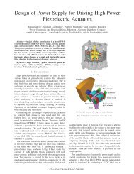
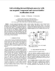
Fig. 1. Different field-orientated control schemes<br />
1-4244-0743-5/07/$20.00 ©2007 IEEE<br />
1459
*<br />
ψ<br />
s<br />
* ψ sa<br />
−<br />
ψ sa<br />
ψ sb<br />
*<br />
* ψ sc<br />
−<br />
ψ sb<br />
−<br />
ψ sc<br />
Sc<br />
Sb<br />
Sa<br />
U dc<br />
Inverter<br />
*<br />
ψ<br />
s<br />
*<br />
T<br />
−<br />
T<br />
−<br />
ψ<br />
s<br />
Switching<br />
table<br />
Sa<br />
Sb<br />
Sc<br />
U dc<br />
Inverter<br />
T *<br />
T<br />
−<br />
a , b,<br />
c<br />
α, β<br />
ψ<br />
s<br />
Flux<br />
Torque<br />
u s<br />
Torque , Flux,<br />
Sector<br />
Estimation<br />
DSC<br />
<strong>Motor</strong><br />
DTC<br />
<strong>Motor</strong><br />
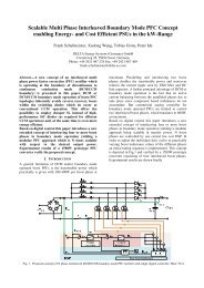
Fig. 2. DSC and DTC block schematics<br />
II. CONTROL APPROACHES<br />
Though R. H. Park [1] introduced rotating reference frames<br />
already in 1929, it took a long time to develop <strong>the</strong> idea <strong>of</strong><br />
field-oriented control (FOC) that is based on <strong>the</strong> fundamental<br />
insight that <strong>the</strong> torque is proportional to <strong>the</strong> cross product <strong>of</strong><br />
stator current and flux i<br />
s<br />
× ψ . The resulting decoupled<br />
r<br />
control <strong>of</strong> torque and field excitation is <strong>the</strong>n quite similar to<br />
DC motor control. Roots <strong>of</strong> FOC started from Germany. As<br />
one <strong>of</strong> <strong>the</strong> first, Hannakam [2] built up a dynamic model <strong>of</strong><br />
induction machine with analog computer in 1959. Then in<br />
1964, Pfaff [4] studied <strong>the</strong> dynamics <strong>of</strong> induction motors with<br />
variable frequency supply. These publications in conjunction<br />
with <strong>the</strong> text book <strong>of</strong> Kovacs and Racz [3] were <strong>the</strong>n <strong>the</strong><br />
building blocks for <strong>the</strong> concept <strong>of</strong> Indirect FOC (IFOC)<br />
presented by Hasse in 1968 [5][35]. Later in 1971, Direct<br />
FOC (DFOC) was developed within Siemens by Blaschke [6].<br />
Both authors proposed an orientation aligned with <strong>the</strong> rotor<br />
flux vector. In <strong>the</strong> mid 1980s, when many researchers worked<br />
on improvements <strong>of</strong> <strong>the</strong> basic FOC, Depenbrock presented <strong>the</strong><br />
Direct Self <strong>Control</strong> (DSC) [17] and Takahashi and Noguchi<br />
<strong>the</strong> Direct Torque <strong>Control</strong> (DTC) [16]. Unlike FOC which<br />
includes pulse width-modulated current control loops, DSC<br />
and DTC are hysteresis controls working directly with stator<br />
flux and torque without having <strong>the</strong> need for an inner current<br />
control loop.<br />
A. Field-Oriented <strong>Control</strong> (FOC)<br />
In <strong>the</strong> concept <strong>of</strong> Indirect FOC (IFOC), flux orientation is<br />
realized only by means <strong>of</strong> feed-forward control, typically by a<br />
calculation <strong>of</strong> <strong>the</strong> slip frequency from <strong>the</strong> reference values,<br />
Fig. 1a. This approach is simple and well performing for <strong>the</strong><br />
speed and position control even at low speeds. However, <strong>the</strong><br />
major drawback is that, <strong>the</strong> orientation <strong>of</strong> <strong>the</strong> control is very<br />
sensitive to <strong>the</strong> rotor resistance, which affects <strong>the</strong> robustness<br />
<strong>of</strong> <strong>the</strong> control. To overcome this problem <strong>the</strong> rotor resistance<br />
has to be estimated online [12][14].<br />
The o<strong>the</strong>r way is <strong>the</strong> Direct FOC (DFOC). The original<br />
approach <strong>of</strong> Blaschke [6] included flux measurement coils to<br />
accomplish <strong>the</strong> flux orientation, Fig. 1b. Instead <strong>of</strong> flux<br />
measurement, DFOC includes usually flux observers to enable<br />
flux orientation, Fig. 1c. The different types <strong>of</strong> flux observers<br />
will be treated in <strong>the</strong> next section.<br />
The concept <strong>of</strong> field orientation is not restricted to rotor<br />
flux orientation but also possible with stator or air-gap flux<br />
[18]. In <strong>the</strong> late 1980s <strong>the</strong>re were few publications on stator<br />
flux orientation [19] that presented some advantages over <strong>the</strong><br />
rotor flux-oriented control. A generalization is <strong>the</strong> concept <strong>of</strong><br />
universal field orientation [27].<br />
B. Direct Self <strong>Control</strong> and Direct Torque <strong>Control</strong><br />
Unlike FOC with stator current as inner control objective,<br />
DSC and DTC govern <strong>the</strong> stator flux by means <strong>of</strong> hysteresis<br />
controls. The overall concept <strong>of</strong> torque control in DSC [17]<br />
and <strong>the</strong> DTC [16] is <strong>the</strong> same, block schematic <strong>of</strong> <strong>the</strong>se<br />
controls are shown in Fig. 2. The difference between <strong>the</strong><br />
techniques is that DSC performs a hexagonal flux trajectory<br />
while that <strong>of</strong> DTC is circular. The DSC was developed for<br />
high power and traction application. Both possess high torque<br />
dynamics compared to FOC. However, both <strong>the</strong> control<br />
techniques have <strong>the</strong> inherent drawbacks <strong>of</strong> variable switching<br />
frequency and higher torque ripple. Since <strong>the</strong>n it has been<br />
continuously worked by researchers to overcome <strong>the</strong>se<br />
inherent drawbacks. These problems opened various roots for<br />
researchers to work on different kinds <strong>of</strong> strategies to avoid<br />
<strong>the</strong> variable switching frequency [22][24][37], but sticking to<br />
<strong>the</strong> fundamental concept <strong>of</strong> torque control.<br />
In order to realize <strong>the</strong> control, ei<strong>the</strong>r DSC or DTC, flux and<br />
torque estimates have to be provided by a flux observer, quite<br />
similar to FOC. Although, mostly <strong>the</strong> so-called voltage model<br />
is mentioned in combination with DTC this is not mandatory,<br />
as <strong>the</strong> control will also run with o<strong>the</strong>r types <strong>of</strong> observers.<br />
III. FLUX AND TORQUE OBSERVERS<br />
Task <strong>of</strong> <strong>the</strong> observer is to provide estimates <strong>of</strong> <strong>the</strong> flux <strong>of</strong><br />
<strong>the</strong> motor using available measured signals such as current,<br />
voltage and speed. Depending on <strong>the</strong> control structure (FOC,<br />
DSC, DTC) ei<strong>the</strong>r stator or rotor flux estimates are needed.<br />
However, since <strong>the</strong> rotor flux can be calculated effectively<br />
from <strong>the</strong> stator flux (and vice versa) as long as <strong>the</strong> current is<br />
available, this does not affect <strong>the</strong> presented main principles.<br />
1460
u s<br />
is<br />
Lr<br />
Lm<br />
RsLr<br />
Lm<br />
LsLr<br />
σ<br />
Lm<br />
−<br />
−<br />
ω 0<br />
1<br />
P<br />
(a)<br />
−<br />
ψ<br />
r<br />
i s<br />
Lm<br />
Rr<br />
Lr<br />
ω rs<br />
−<br />
(b)<br />
1<br />
P<br />
Rr<br />
− jωrs<br />
Lr<br />
ψ r<br />
u s<br />
−<br />
−<br />
1<br />
: Integrator<br />
P<br />
2<br />
Lm<br />
σ = 1−<br />
LsLr<br />
1<br />
P<br />
Rs<br />
σLs<br />
ψ<br />
s<br />
Rr<br />
σLsLr<br />
− RsLm<br />
σLsLr<br />
(c)<br />
ω rs<br />
−<br />
1<br />
P<br />
Rr<br />
− j<br />
Lr<br />
ω<br />
ψ<br />
r<br />
rs<br />
i s<br />
u s<br />
Rs + σLsP<br />
ω rs<br />
−<br />
(d)<br />
ψ<br />
2<br />
Lr r<br />
Lm(<br />
Rr − jω rs Lr)<br />
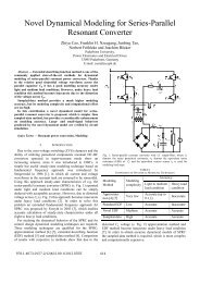
Fig. 3. Open-loop observers: a) Voltage/stator model b) Current/Rotor model<br />
c) Voltage and speed model d) Voltage current and speed model<br />
u s<br />
B<br />
ω rs<br />
K<br />
A( ω r<br />
)<br />
ψˆ<br />
r<br />
C<br />
i s<br />
− î s<br />
u s<br />
i s<br />
ω rs<br />
1<br />
P<br />
j r<br />
e − θ<br />
Lm<br />
1 + τ rP<br />
j r<br />
e θ<br />
Current<br />
Model<br />
−<br />
Kp<br />
Ki<br />
P<br />
Rs<br />
−<br />
1<br />
P<br />
σLs<br />
−<br />
Voltage<br />
Model<br />
ψˆ<br />
r<br />
(a)<br />
(b)<br />
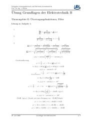
Fig. 4. Closed-loop observers: a) Luenberger type b) Gopinath type<br />
Once a flux estimate is available, also a torque estimate can<br />
easily be computed. Thus, all <strong>the</strong> flux observers can also<br />
provide torque estimates.<br />
A. Open-Loop observers<br />
Open-loop observers do not include measures <strong>of</strong> error<br />
feedback. They result in a straight-forward way from <strong>the</strong><br />
motor modeling.<br />
Voltage or Stator Model (inherently speed sensorless): The<br />
first flux estimator proposed in early 1970s [7] used for <strong>the</strong><br />
FOC was based on <strong>the</strong> stator circuit. The estimator is a simple<br />
integrator calculating <strong>the</strong> stator flux vector from<br />
ψ =<br />
∫(<br />
u<br />
s<br />
− Rsi<br />
s<br />
) dt , and from that <strong>the</strong> rotor flux. The<br />
s<br />
method is very sensitive to <strong>of</strong>fsets (such as motor current) due<br />
to <strong>the</strong> pure integration. The o<strong>the</strong>r drawback is erroneous<br />
estimation at low speeds, since <strong>the</strong> temperature dependent<br />
drop <strong>of</strong> R sis<br />
dominates over <strong>the</strong> motor terminal voltage. In<br />
order to overcome <strong>the</strong> <strong>of</strong>fset problem, a low pass filter (LPF)<br />
for <strong>the</strong> flux estimation is utilized in [14], and shown in Fig.<br />
3a. It avoids <strong>the</strong> estimator windup but restricts to limit <strong>the</strong> low<br />
speed operation much above <strong>the</strong> cut <strong>of</strong>f frequency <strong>of</strong> LPF.<br />
However, this model works very well at higher speeds and<br />
field weakening [19].<br />
Current or Rotor Model: Almost at <strong>the</strong> same time in 1974<br />
<strong>the</strong> DFOC presented in [8] with <strong>the</strong> rotor model, which is also<br />
well known as current model. The performance <strong>of</strong> this current<br />
model is sensitive to <strong>the</strong> rotor resistance at higher slips [20],<br />
[28], shown in Fig. 3b. However, <strong>the</strong>re is no particular<br />
problem for operation at low speeds.<br />
Voltage-Current and Speed Model: This model in <strong>the</strong> same<br />
publication [8] proposed, and <strong>the</strong> details <strong>of</strong> implementation<br />
can be seen in [13]. This is also known as open loop estimator<br />
with cancellation technique, this technique suffers from many<br />
issues like differentiation <strong>of</strong> current, division by speed and an<br />
inherently high parameter sensitivity [28]. The model is also<br />
shown in Fig. 3d.<br />
Voltage-Speed Model: This is a full order flux observer,<br />
which resembles <strong>the</strong> electrical model <strong>of</strong> <strong>the</strong> motor. The<br />
observer uses <strong>the</strong> motor voltage and speed and calculates <strong>the</strong><br />
stator and rotor fluxes, shown in Fig 3c. The utilization <strong>of</strong><br />
such a model for <strong>the</strong> control can be found in [13].<br />
The detailed error analysis due to <strong>the</strong> parameter variation<br />
for <strong>the</strong> above estimators can be found in <strong>the</strong> doctorate <strong>the</strong>sis<br />
<strong>of</strong> Zägelein [15].<br />
B. Closed-Loop observers<br />
The well known closed-loop observers are based on<br />
Luenberger type observer and Gopinath’s type observer. Both<br />
types allow an error feedback.<br />
Luenberger Observer: A full-order observer is based on <strong>the</strong><br />
Voltage-Speed model <strong>of</strong> <strong>the</strong> motor, where motor current is <strong>the</strong><br />
output quantity <strong>of</strong> <strong>the</strong> state space model. This estimated<br />
1461
Sensorless<br />
control<br />
Fundamental wave<br />
model<br />
Exploited<br />
anisotropies<br />
Voltage<br />
model[38]<br />
- 2% <strong>of</strong> rated speed<br />
- Error <strong>of</strong> 0.5 rated slip<br />
Open loop<br />
observer<br />
- ≥ 2Hz<br />
MRAS<br />
[25]<br />
- Error <strong>of</strong> 0.5 rated slip<br />
Full order<br />
non - linear [26 33]<br />
- 0.02 pu [33]<br />
- Error <strong>of</strong> 0.5 rated slip<br />
Closed loop<br />
observer<br />
Sliding mode<br />
[36]<br />
- 0.002 pu with load<br />
- Error <strong>of</strong> 0.5 rated slip<br />
Rotor slot<br />
Mag - inductance<br />
saturation<br />
<strong>Art</strong>ificial<br />
sailiency<br />
Fig. 5. Different sensorless control schemes<br />
current is used to compare with <strong>the</strong> actual measured current<br />
and drive <strong>the</strong> error in <strong>the</strong> feedback path to improve <strong>the</strong><br />
performance <strong>of</strong> <strong>the</strong> observer. Such a structure is shown in Fig.<br />
4a. The utilization <strong>of</strong> such a scheme can be traced back to <strong>the</strong><br />
early 1980s in [15]. In this <strong>the</strong>sis, <strong>the</strong> author has provided in<br />
depth for error analysis with <strong>the</strong> parameter variations and also<br />
presented some simple optimization techniques for <strong>the</strong><br />
feedback circuit to minimize <strong>the</strong> flux magnitude and phase<br />
errors. Researchers fur<strong>the</strong>r explored this type <strong>of</strong> observer with<br />
<strong>the</strong> stochastic approach (based on Kalman Theory) [23].<br />
Gopinath’s type observer: The closed-loop flux observer is<br />
formed from <strong>the</strong> two most desirable open-loop estimators<br />
(presented above) which are referred as voltage model and<br />
current model, Fig. 4b. The smooth transition between <strong>the</strong>se<br />
two models is governed by <strong>the</strong> bandwidth [29], which is<br />
determined by <strong>the</strong> proportional and integral gains K P, K I <strong>of</strong><br />
<strong>the</strong> system.<br />
IV. SPEED SENSORLESS CONTROL<br />
Speed and position sensors are undesired due to various<br />
reasons as cost, cabling, robustness, and construction<br />
constraints. Many different approaches have been presented<br />
for speed sensorless induction motor control, e.g. [25], [26],<br />
[38].<br />
Methods which are based on models assuming sinusoidal<br />
field distribution belong to <strong>the</strong> class <strong>of</strong> fundamental-wave<br />
methods. Many approaches <strong>of</strong> this class are derived from<br />
classical motor modeling or are originating from system<br />
identification techniques. All <strong>the</strong>se methods work more or less<br />
reliably for medium to higher speeds. The principle problem<br />
with fundamental-wave speed estimation is that <strong>the</strong> induction<br />
motor becomes an unobservable system at zero stator<br />
frequency. Many efforts were spent to reduce <strong>the</strong> practical<br />
margin <strong>of</strong> minimum speed or to avoid zero frequency by<br />
appropriate manipulations <strong>of</strong> <strong>the</strong> flux magnitude.<br />
If zero frequency is an issue, spatial anisotropies<br />
(saliencies) <strong>of</strong> <strong>the</strong> motor like magnetic saturation or slot<br />
harmonics could be utilized to detect speed and position <strong>of</strong> <strong>the</strong><br />
rotor or <strong>the</strong> flux, respectively. Two main streams were<br />
presented working ei<strong>the</strong>r with injection <strong>of</strong> additional<br />
harmonics [31] or applying step-like test signals [30].<br />
However, exploitation <strong>of</strong> anisotropies <strong>of</strong> induction motors is<br />
much harder compared to synchronous motors, since natural<br />
saliencies <strong>of</strong> normal induction motors are very small due to<br />
skewing and optimized numbers <strong>of</strong> stator and rotor slots.<br />
Thus, motors with particular properties and individual tuning<br />
were required. Fig. 5 shows an overview about <strong>the</strong> various<br />
methods <strong>of</strong> speed sensorless control [38].<br />
V. PARAMETER IDENTIFICATION<br />
Sophisticated model-based controls as FCO or DTC need<br />
precise information about <strong>the</strong> motor parameters like stator,<br />
rotor and mutual inductances and stator and rotor resistances.<br />
A lot <strong>of</strong> parameter identification techniques have been<br />
proposed, which can be grouped as <strong>of</strong>f-line and on-line<br />
identification. Off-line identification takes place during<br />
commissioning or turning-on, while on-line identification is<br />
carried out during <strong>the</strong> normal operation. First proposals for<br />
<strong>of</strong>f-line identification and self-commissioning are presented in<br />
<strong>the</strong> 1980 [21]. Up to today <strong>the</strong>re are multitudes <strong>of</strong> publications<br />
and text books on parameter identification. Normally, <strong>of</strong>f-line<br />
identification has to be done at standstill, because usually <strong>the</strong><br />
shaft is not allowed to rotate.<br />
VI. INDUSTRIAL STANDARDS IN INDUCTION MOTOR DRIVES<br />
Today, three-phase induction motor drives are employed in<br />
different industrial areas with a wide power range starting<br />
from few 100W to several MW. Drives industry is very<br />
thankful to <strong>the</strong> present generation <strong>of</strong> powerful<br />
microprocessors, which is responsible for <strong>the</strong> realization <strong>of</strong><br />
control functions within short cost margins. However, even<br />
today, cost <strong>of</strong> controller hardware is a limiting constraint,<br />
particularly at <strong>the</strong> low-power and low performance drives.<br />
Main market share <strong>of</strong> about 80-90% are simple drives with<br />
low dynamic requirements like pumps and fans. All <strong>the</strong>se<br />
drives are working without speed sensors. The control<br />
principle is still based on v/f control. In this segment <strong>the</strong>re is<br />
no need to introduce more powerful controls.<br />
More sophisticated control is needed for all kinds <strong>of</strong> drives<br />
1462
that require high dynamic speed or torque regulation or high<br />
torque accuracy. Some examples are elevators, cranes, tooling<br />
machines and many kinds <strong>of</strong> industrial automation drives.<br />
Even drives for steel and paper mills, though it seems <strong>the</strong>y are<br />
only continuously running, demand highest performance due<br />
to <strong>the</strong> extreme quality <strong>of</strong> <strong>the</strong> technologies. For most <strong>of</strong> <strong>the</strong>se<br />
applications industrial standard products are available that<br />
come ei<strong>the</strong>r with FOC or DTC. Many results from research<br />
have found <strong>the</strong>ir way to <strong>the</strong>se industrial products.<br />
However, it has to be distinguished between standard <strong>of</strong>f<strong>the</strong>-shelf<br />
products and those that are individually designed or<br />
adapted for particular applications, typically in <strong>the</strong> high power<br />
range.<br />
Installation and commissioning <strong>of</strong> standard drives is <strong>of</strong>ten<br />
done by technical staff that is not familiar with <strong>the</strong> details <strong>of</strong><br />
AC motor control. Thus, higher level methods as Luenberger<br />
observer or extended Kalman filter, requiring special<br />
education are usually not adopted. These controls are results<br />
<strong>of</strong> compromises between performance, cost, and, not least,<br />
easy usability.<br />
Self-commissioning functions are growing. However, that<br />
is <strong>of</strong>ten done not by means <strong>of</strong> parameter identification<br />
techniques, but using databases with motor data <strong>of</strong> <strong>the</strong><br />
supplier’s list.<br />
Individually designed controls, e.g. for traction drives and<br />
large industrial drives is <strong>of</strong>ten much more sophisticated and<br />
close to latest research. In that business, an experienced staff<br />
is usually responsible for development as well as for<br />
commissioning.<br />
Though most industrial controls allow also speed sensorless<br />
operation, typically degradations in performance have to be<br />
accepted. Highly performing sensorless drives with dynamic<br />
and precise torque tracking even at low speed and during<br />
regenerative braking are only a very small niche, e.g. when it<br />
is difficult to mount a speed sensor in a wheel hub drive.<br />
VII. FUTURE TRENDS AND NEEDS<br />
Today’s industrial induction motor drives have matured to a<br />
relatively high level compared with needs. To accomplish that<br />
level it took about a decade or more to transfer research<br />
results to today’s industrial standards. However, what are <strong>the</strong><br />
open or upcoming issues and future trends?<br />
• Reliable self-commissioning will become more and more<br />
mandatory.<br />
• Depending on <strong>the</strong> preceding item, market share <strong>of</strong> vector<br />
controls as FOC/DSC will grow compared to v/f control.<br />
• Servo-type drives seem to be <strong>of</strong> decreasing importance,<br />
because this area is captured more and more by permanent<br />
magnet synchronous motors. However:<br />
• Because induction motors possess low inertia and are free<br />
<strong>of</strong> cogging torque, <strong>the</strong>re is a growing market segment <strong>of</strong><br />
high speed and test stand drives requiring smoo<strong>the</strong>st<br />
stationary torque, but also capability <strong>of</strong> rapid torque and<br />
speed changes in order to apply desired test pr<strong>of</strong>iles.<br />
• Safety aspects are getting more important. That addresses<br />
s<strong>of</strong>tware development standards as already partly<br />
introduced as well as operational measures like<br />
redundancy or fallback operation.<br />
• Efficiency-optimized operation will grow more importance<br />
with respect to energy saving demands.<br />
• <strong>Control</strong>ler hardware which is based today on microprocessors<br />
or DSP may change in <strong>the</strong> future more and<br />
more towards ASICs or FPGA. A growing number <strong>of</strong><br />
contributions are observed in this area.<br />
REFERENCES<br />
[1] Park, R.H., “Two reaction <strong>the</strong>ory <strong>of</strong> synchronous machine –<br />
Generalized method <strong>of</strong> analysis – Part 1,” AIEE Trans., 48, July 1929,<br />
pp. 716-727<br />
[2] Hannakam, L., “Dynamic modelling <strong>of</strong> induction machine on an<br />
analogue computer”, Regelungstechnik, 1959<br />
[3] Kovac, K.P., Racz, I., “Transiente Vorgänge in Wechselstrommaschinen”<br />
Verlag der ungarischen Akademie der Wissenschaften,<br />
Budapest; 1959<br />
[4] Pfaff, G., “Zur Dynamik des Asynchronmotors bei Drehzahlsteuerung<br />
mittels veränderlicher Speisefrequenz” ETZ-A 85, H. 22, 1964, pp.<br />
719–724<br />
[5] Hasse, K., “Zum dynamischen Verhalten der Asynchronmaschine bei<br />
Betrieb mit variabler Ständerfrequenz und Ständerspannung” ETZ-A<br />
89, 1968, pp. 387-391<br />
[6] Blaschke, F., “The principle <strong>of</strong> field orientation applied to <strong>the</strong> new<br />
trans-vector closed-loop control system for rotating field machines”<br />
Siemens-Review 39, 1972, pp. 217–220<br />
[7] Becker, H., “Dynamisch hochwertige Drehzahlreglung einer<br />
umrichtergespeisten Asynchronmaschine” Regelungstechnische<br />
Praxis und Prozessrechentechnik 1973, pp. 217-221<br />
[8] Blaschke, F., Böhm, K., “Verfahren der Felderfassung bei der<br />
Regelung stromrichtergespeister Asynchronmaschinen” IFAC-<br />
Symposium, control in power electronics and electric drives,<br />
Düsseldorf, 1974, pp. 635-649<br />
[9] Bühler, H., “Einführung in die Theorie geregelter Drehstromantriebe”<br />
Band 1, 2, Birkhäuser Verlag, Basel, 1977<br />
[10] Flügel, W., “Steuerung des Flusses von umrichtergespeisten<br />
Asynchronmaschinen über Entkopplungsnetzwerke” ETZ-Archiv,<br />
1979, pp. 347-350<br />
[11] Gabriel, R., Leonhard, W., Noedby, C.J., “Field-Oriented control <strong>of</strong> a<br />
standard AC motor using microprocessor “ IEEE Trans. IA,<br />
March/April 1980<br />
[12] Garces, L., “Parameter Adaptation for <strong>the</strong> Speed <strong>Control</strong>led AC Drive<br />
with a Squirrel-Cage <strong>Induction</strong> <strong>Motor</strong> Operated with Variable<br />
Frequency Power Supply”, IEEE Trans. IA, 16, Mar/April 1980, pp.<br />
173-178<br />
[13] Flügel, W., “Drehzahlregelung umrichtergespeister Asynchronmaschinen<br />
bei Steuerung des Flusses durch Entkopplungsnetzwerke”<br />
Dissertation, TU München, 1981<br />
[14] Gabriel, R., “Feldorientierte Regelung einer Asynchronmaschine mit<br />
einem Mikrorechner” Dissertation, TU Braunschweig, 1982<br />
[15] Zägelein, W., “Drehzahlregelung des Asynchronmotors unter<br />
Verwendung eines Beobachters mit geringer Parameterempfindlichkeit”<br />
Dissertation, Universität Erlangen, 1984<br />
[16] Takahashi, I., Naguchi, T., “A new quick response and high<br />
efficiency control strategy <strong>of</strong> an induction motor,” IEEE Trans. IA,<br />
1986<br />
[17] Depenbrock, M., “Direct self control <strong>of</strong> inverter fed induction<br />
machines,” IEEE Trans. PE, 1988<br />
[18] Ho, E.Y.Y., Sen, P.C., “Decoupling control <strong>of</strong> induction motor<br />
drives” IEEE Trans. IE, 35, 1988<br />
[19] Xingyi Xu, De Doncker, R., Novotny, D., “A stator flux oriented<br />
induction machine drive,” IEEE-PESC Japan Kyoto 1988, pp. 870-<br />
876<br />
[20] Verghese, G. C., Sanders, S. R., “Observer for flux estimation in<br />
induction machines,” IEEE Trans. IE, 35, Feb. 1988, pp. 85-94<br />
[21] Schierling, H., “Self-Commissioning- a novel feature <strong>of</strong> modern<br />
<strong>Induction</strong> motor drives,” IEE conf on Power Electronics and variable<br />
speed drives, 1988, pp. 287-290<br />
1463
[22] Jänecke, M., Kremer, R., Steuerwald, G., “Direct self-control, a novel<br />
method <strong>of</strong> controlling asynchronous machines in traction<br />
applications,” in Proc. EPE Conf., Germany, 1989, pp. 75–81<br />
[23] Böcker, J., Janning, J., “Discrete time observer for PWM inverter-fed<br />
induction motors,” EPE Firenze 1991, pp. 2.171- 2.176<br />
[24] Habetler, T.G., Pr<strong>of</strong>umo, F., Pastorelli, M., Tolbert, L.M., “Direct<br />
Torque control <strong>of</strong> induction machines using space vector<br />
modulation,” IEEE Trans. IA, Sept/Oct, 1992<br />
[25] Schauder, C., “Adaptive speed identification for Vector <strong>Control</strong> <strong>of</strong><br />
<strong>Induction</strong> <strong>Motor</strong>s without Rotational Transducers,” IEEE Trans. IA<br />
28-5, Sept/Oct, 1992, pp. 1054-1061<br />
[26] Kubato, H., Matsuse, K., Nakano, T., “DSP based Speed Adaptive<br />
Flux observer <strong>of</strong> <strong>Induction</strong> <strong>Motor</strong>,” IEEE Trans. IA 29-2<br />
March/April, 1993, pp. 344-348<br />
[27] De Doncker, R., Novotny, D., “The universal field oriented<br />
controller” IEEE Trans. IA, 30-1, Jan/Feb, 1994<br />
[28] Jansen, P.L., Lorenz, R.D., “ A physical insight full approach to<br />
design and accuracy assessment <strong>of</strong> flux observers for field oriented<br />
induction machine drives” IEEE Trans. IA, 30, Jan/Feb 1994<br />
[29] Jansen, P.L., Lorenz, R.D., Novotny, D.W., “Observer-Based Direct<br />
field orientation: Analysis and comparison <strong>of</strong> alternative methods”<br />
IEEE Trans. IA, 30 July/August 1994, pp. 945- 953<br />
[30] Schrödl, M., “Sensorless control <strong>of</strong> AC machines at low speed and<br />
standstill based on <strong>the</strong> inform method,” in Proc. IEEE IAS Annu.<br />
Meeting, Pittsburgh, PA, Sep 30–Oct 4, 1996, pp. 270–277<br />
[31] Degner, M.W., Lorenz, R.D., “Using multiple saliencies for <strong>the</strong><br />
estimation <strong>of</strong> flux, position and velocity in AC machines,” IEEE<br />
Trans. IA, 34-5, Sept/Oct 1998, pp. 1097-1104<br />
[32] Vas, P., “Sensorless vector and direct torque control” Oxford<br />
University press 1998<br />
[33] Maes, J., Melkebeek, J.A., “Speed sensorless DTC using an adaptive<br />
flux observer” IEEE Trans. IA, 36-3, 2000, pp. 778-785<br />
[34] Leonhard, W., “<strong>Control</strong> <strong>of</strong> Electric Drives” 3 rd edition Springer 2001<br />
[35] Hasse, K., “Feldorientierte Regelung im Rückblick” presented at<br />
IEEE IAS/PELS/IES German chapter meeting, Braunschweig, 22<br />
Nov 2001<br />
[36] Lascu, C., Boldea, I., Blaabjerg, F., “Very low speed sensorless<br />
variable structure control <strong>of</strong> induction machine drives without signal<br />
injection,” in Proc. IEEE IEMDC Madison, Jun 2003<br />
[37] Buja, G.S., Kazmierkowski, M.P., “Direct torque control <strong>of</strong> PWM<br />
inverter-fed AC motors - a survey” IEEE Trans. IE, 51, Aug. 2004 pp.<br />
744-757<br />
[38] Holtz, J., “Sensorless <strong>Control</strong> <strong>of</strong> <strong>Induction</strong> Machines – With or<br />
Without Signal Injection?,” IEEE Trans. IE, 53-1, Feb 2006, pp. 7- 30<br />
1464


![[ ] Ï - Fachgebiet Leistungselektronik und Elektrische Antriebstechnik](https://img.yumpu.com/51151382/1/184x260/-i-fachgebiet-leistungselektronik-und-elektrische-antriebstechnik.jpg?quality=85)