
Create successful ePaper yourself
Turn your PDF publications into a flip-book with our unique Google optimized e-Paper software.
JESD79E<br />
Page 11<br />
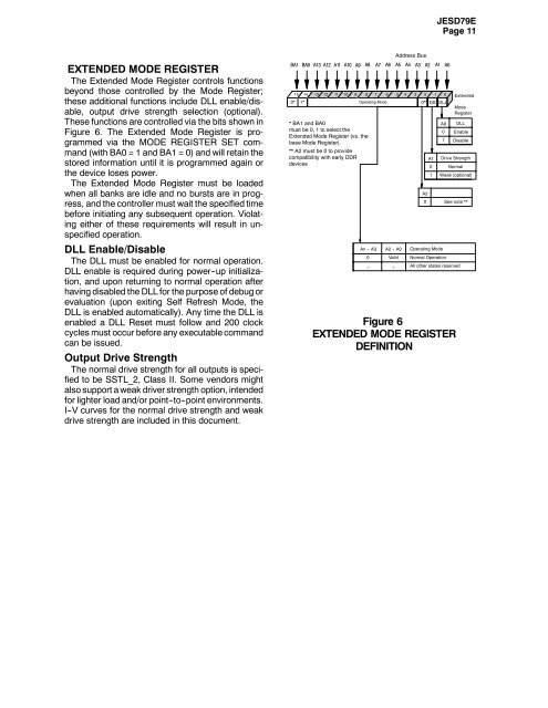
EXTENDED MODE REGISTER<br />
The Extended Mode Register controls functions<br />
beyond those controlled by the Mode Register;<br />
these additional functions include DLL enable/disable,<br />
output drive strength selection (optional).<br />
These functions are controlled via the bits shown in<br />
Figure 6. The Extended Mode Register is programmed<br />
via the MODE REGISTER SET command<br />
(with BA0 = 1 and BA1 = 0) and will retain the<br />
stored information until it is programmed again or<br />
the device loses power.<br />
The Extended Mode Register must be loaded<br />
when all banks are idle and no bursts are in progress,<br />
and the controller must wait the specified time<br />
before initiating any subsequent operation. Violating<br />
either of these requirements will result in unspecified<br />
operation.<br />
DLL Enable/Disable<br />
The DLL must be enabled for normal operation.<br />
DLL enable is required during power--up initialization,<br />
and upon returning to normal operation after<br />
having disabled the DLL for the purpose of debug or<br />
evaluation (upon exiting Self Refresh Mode, the<br />
DLL is enabled automatically). Any time the DLL is<br />
enabled a DLL Reset must follow and 200 clock<br />
cycles must occur before any executable command<br />
can be issued.<br />
Output Drive Strength<br />
The normal drive strength for all outputs is specified<br />
to be SSTL_2, Class II. Some vendors might<br />
also support a weak driver strength option, intended<br />
for lighter load and/or point--to--point environments.<br />
I--V curves for the normal drive strength and weak<br />
drive strength are included in this document.<br />
BA1 BA0 A13 A12 A11 A10<br />
15 14<br />
0* 1*<br />
13<br />
12<br />
10<br />
* BA1 and BA0<br />
must be 0, 1 to select the<br />
Extended Mode Register (vs. the<br />
base Mode Register).<br />
11<br />
** A2 must be 0 to provide<br />
compatibility with early DDR<br />
devices<br />
A9 A8 A7 A6 A5 A4 A3 A2 A1 A0<br />
9 8 7 6 5 4 3 2 1 0<br />
Operating Mode<br />
0** DS DLL<br />
An -- A3<br />
0<br />
--<br />
A2 -- A0<br />
Valid<br />
--<br />
Address Bus<br />
A1<br />
0<br />
1<br />
A0<br />
0<br />
1<br />
DLL<br />
Enable<br />
Disable<br />
Operating Mode<br />
Normal Operation<br />
All other states reserved<br />
Extended<br />
Mode<br />
Register<br />
Drive Strength<br />
Normal<br />
Weak (optional)<br />
A2<br />
0 See note **<br />
Figure 6<br />
EXTENDED MODE REGISTER<br />
DEFINITION