Vehicle Speed Sensor Tech Note - Daytona Sensors LLC
Vehicle Speed Sensor Tech Note - Daytona Sensors LLC
Vehicle Speed Sensor Tech Note - Daytona Sensors LLC

Create successful ePaper yourself
Turn your PDF publications into a flip-book with our unique Google optimized e-Paper software.
<strong>Daytona</strong> <strong>Sensor</strong>s <strong>LLC</strong><br />
Engine Controls and Instrumentation Systems<br />
<strong>Tech</strong> <strong>Note</strong> for <strong>Vehicle</strong><br />
<strong>Speed</strong> Hall Effect <strong>Sensor</strong><br />
CAUTION: CAREFULLY READ INSTRUCTIONS BEFORE PROCEEDING<br />
OVERVIEW<br />
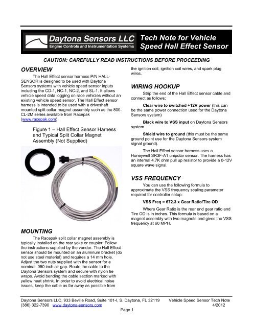
The Hall Effect sensor harness P/N HALL-<br />
SENSOR is designed to be used with <strong>Daytona</strong><br />
<strong>Sensor</strong>s systems with vehicle speed sensor inputs<br />
including the CD-1, NC-1, NC-2, and SL-1. It allows<br />
vehicle speed data logging on race vehicles without an<br />
existing vehicle speed sensor. The Hall Effect sensor<br />
harness is intended to be used with a driveshaft<br />
mounted split collar magnet assembly such as the 800-<br />
CL-2M series available from Racepak<br />
(www.racepak.com).<br />
Figure 1 – Hall Effect <strong>Sensor</strong> Harness<br />
and Typical Split Collar Magnet<br />
Assembly (Not Supplied)<br />
the ignition coil, ignition coil wires, and spark plug<br />
wires.<br />
WIRING HOOKUP<br />
Strip the end of the Hall Effect sensor cable and<br />
connect as follows:<br />
Clear wire to switched +12V power (this can<br />
be the same power connection used for the <strong>Daytona</strong><br />
<strong>Sensor</strong>s system)<br />
Black wire to VSS input on <strong>Daytona</strong> <strong>Sensor</strong>s<br />
system<br />
Shield wire to ground (this must be the same<br />
ground point use for the <strong>Daytona</strong> <strong>Sensor</strong>s system<br />
signal ground).<br />
The Hall Effect sensor harness uses a<br />
Honeywell SR3F-A1 unipolar sensor. The harness has<br />
an internal 4.7K ohm pull up resistor to provide a 0-12V<br />
square wave signal.<br />
MOUNTING<br />
The Racepak split collar magnet assembly is<br />
typically installed on the rear yoke or coupler. Follow<br />
the instructions supplied by the vendor. The Hall Effect<br />
sensor should be mounted on an aluminum bracket (do<br />
not use steel material) and requires a 14 mm hole.<br />
Adjust the two nuts supplied with the sensor for a<br />
nominal .050 inch air gap. Route the cable to the<br />
<strong>Daytona</strong> <strong>Sensor</strong>s system and secure with nylon tie<br />
wraps. Avoid bending the cable section marked with<br />
yellow heat shrink. In order to avoid electrical noise<br />
issues, keep the cable as far away as possible from<br />
VSS FREQUENCY<br />
You can use the following formula to<br />
approximate the VSS frequency scaling parameter<br />
required for controller setup:<br />
VSS Freq = 672.3 x Gear Ratio/Tire OD<br />
Where Gear Ratio is the rear end gear ratio and<br />
Tire OD is in inches. This formula is based on a<br />
magnet assembly with two magnets and gives the VSS<br />
frequency at 60 MPH.<br />
<strong>Daytona</strong> <strong>Sensor</strong>s <strong>LLC</strong>, 933 Beville Road, Suite 101-I, S. <strong>Daytona</strong>, FL 32119 <strong>Vehicle</strong> <strong>Speed</strong> <strong>Sensor</strong> <strong>Tech</strong> <strong>Note</strong><br />
(386) 322-7390 www.daytona-sensors.com 4/2012<br />
Page 1
HALL EFFECT SENSOR NOTES<br />
Figure 2 shows the actual connections made to<br />
a typical Hall effect sensor. The 4.7K ohm pullup<br />
resistor is required in all Hall effect sensor applications.<br />
<strong>Note</strong> that the wire colors shown are the actual leads<br />
coming from the sensor (our prefabricated harness<br />
uses shielded cable with different color coding).<br />
Figure 2 – Hall Effect <strong>Sensor</strong> Connections<br />
SWITCHED +12V<br />
RED<br />
HALL<br />
EFFECT<br />
SENSOR<br />
4.7K OHM<br />
1/2 WATT<br />
RESISTOR<br />
SIGNAL<br />
OUTPUT<br />
SR3F-A1: GREEN<br />
1GT101DC: WHITE<br />
BLACK<br />
GROUND<br />
The Honeywell SR3F-A1 Hall effect sensor<br />
requires a magnet wheel. In some cases, it may be<br />
more convenient to use a gear tooth type sensor.<br />
These include an internal magnet and allow sensing<br />
the passage of steel gear teeth. We recommend the<br />
Honeywell 1GT101DC. Both Honeywell parts are<br />
available from Digi-Key (www.digikey.com).<br />
<strong>Daytona</strong> <strong>Sensor</strong>s <strong>LLC</strong>, 933 Beville Road, Suite 101-I, S. <strong>Daytona</strong>, FL 32119 <strong>Vehicle</strong> <strong>Speed</strong> <strong>Sensor</strong> <strong>Tech</strong> <strong>Note</strong><br />
(386) 322-7390 www.daytona-sensors.com 4/2012<br />
Page 2