WEGO IIID 8-Pack Tech Note - Daytona Sensors LLC
WEGO IIID 8-Pack Tech Note - Daytona Sensors LLC
WEGO IIID 8-Pack Tech Note - Daytona Sensors LLC

Create successful ePaper yourself
Turn your PDF publications into a flip-book with our unique Google optimized e-Paper software.
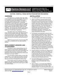
<strong>Daytona</strong> <strong>Sensors</strong> <strong>LLC</strong><br />
Engine Controls and Instrumentation Systems<br />
<strong>Tech</strong> <strong>Note</strong> for <strong>WEGO</strong> <strong>IIID</strong><br />
8-<strong>Pack</strong> for V8 Applications<br />
CAUTION: CAREFULLY READ INSTRUCTIONS BEFORE PROCEEDING<br />
OVERVIEW<br />
The <strong>WEGO</strong> <strong>IIID</strong> 8-<strong>Pack</strong> is a complete kit<br />
intended for individual cylinder air/fuel ratio (AFR)<br />
monitoring of V8 engines on race vehicles. Four dual<br />
channel <strong>WEGO</strong> <strong>IIID</strong> units are connected to an existing<br />
data acquisition system. For dyno installations, refer to<br />
the additional material on pages 3-4.<br />
MOUNTING<br />
Two <strong>WEGO</strong> <strong>IIID</strong> units are required for each<br />
cylinder bank. The individual units can be secured by<br />
means of two #8 screws through the mounting flanges.<br />
Mount the units as far away as possible from the<br />
ignition system. Use nylon tie wraps to secure the wire<br />
harness near the units.<br />
VEHICLE WIRING HOOKUP<br />
If your race vehicle uses any type of CD<br />
(capacitive discharge) ignition such as the MSD 6, 7, or<br />
8 series, you must properly ground and filter the<br />
ignition unit. Unless your ignition unit is directly<br />
connected to the battery terminals, you must<br />
install a filter capacitor such as MSD P/N 8830 or<br />
the 12000 uF 25 volt part described in the next<br />
paragraph. Visit www.msdignition.com, download the<br />
MSD 8 installation instructions, and refer to Figure 1 on<br />
the MSD instructions as a guide for installing the filter<br />
capacitor and grounding the ignition system. Do not<br />
ground your <strong>WEGO</strong> <strong>IIID</strong> units or data acquisition<br />
system to the same ground point used for the ignition<br />
system.<br />
CAUTION: The output of the <strong>WEGO</strong> <strong>IIID</strong><br />
is a low level 0-5 volt analog signal.<br />
Noise from an improperly grounded<br />
and filtered race ignition system will<br />
cause data acquisition errors.<br />
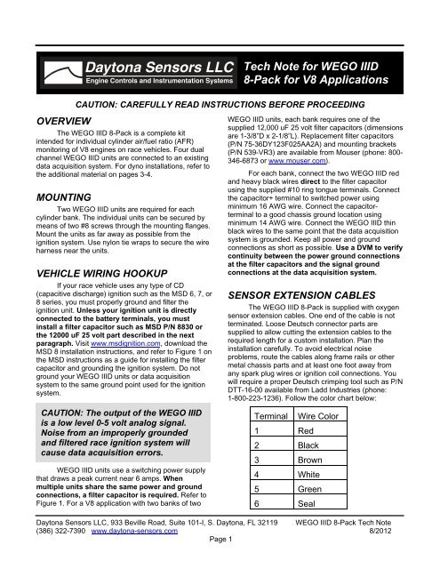
<strong>WEGO</strong> <strong>IIID</strong> units use a switching power supply<br />
that draws a peak current near 6 amps. When<br />
multiple units share the same power and ground<br />
connections, a filter capacitor is required. Refer to<br />
Figure 1. For a V8 application with two banks of two<br />
<strong>WEGO</strong> <strong>IIID</strong> units, each bank requires one of the<br />
supplied 12,000 uF 25 volt filter capacitors (dimensions<br />
are 1-3/8”D x 2-1/8”L). Replacement filter capacitors<br />
(P/N 75-36DY123F025AA2A) and mounting brackets<br />
(P/N 539-VR3) are available from Mouser (phone: 800-<br />
346-6873 or www.mouser.com).<br />
For each bank, connect the two <strong>WEGO</strong> <strong>IIID</strong> red<br />
and heavy black wires direct to the filter capacitor<br />
using the supplied #10 ring tongue terminals. Connect<br />
the capacitor+ terminal to switched power using<br />
minimum 16 AWG wire. Connect the capacitorterminal<br />
to a good chassis ground location using<br />
minimum 14 AWG wire. Connect the <strong>WEGO</strong> <strong>IIID</strong> thin<br />
black wires to the same point that the data acquisition<br />
system is grounded. Keep all power and ground<br />
connections as short as possible. Use a DVM to verify<br />
continuity between the power ground connections<br />
at the filter capacitors and the signal ground<br />
connections at the data acquisition system.<br />
SENSOR EXTENSION CABLES<br />
The <strong>WEGO</strong> <strong>IIID</strong> 8-<strong>Pack</strong> is supplied with oxygen<br />
sensor extension cables. One end of the cable is not<br />
terminated. Loose Deutsch connector parts are<br />
supplied to allow cutting the extension cables to the<br />
required length for a custom installation. Plan the<br />
installation carefully. To avoid electrical noise<br />
problems, route the cables along frame rails or other<br />
metal chassis parts and at least one foot away from<br />
any spark plug wires or ignition coil connections. You<br />
will require a proper Deutsch crimping tool such as P/N<br />
DTT-16-00 available from Ladd Industries (phone:<br />
1-800-223-1236). Follow the color chart below:<br />
Terminal<br />
1 Red<br />
Wire Color<br />
2 Black<br />
3 Brown<br />
4 White<br />
5 Green<br />
6 Seal<br />
<strong>Daytona</strong> <strong>Sensors</strong> <strong>LLC</strong>, 933 Beville Road, Suite 101-I, S. <strong>Daytona</strong>, FL 32119 <strong>WEGO</strong> <strong>IIID</strong> 8-<strong>Pack</strong> <strong>Tech</strong> <strong>Note</strong><br />
(386) 322-7390 www.daytona-sensors.com 8/2012<br />
Page 1
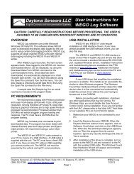
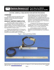
Figure 1 – Typical Vehicle Hookup for Multiple <strong>WEGO</strong> <strong>IIID</strong> Systems<br />
BOSCH<br />
LSU 4.2<br />
BOSCH<br />
LSU 4.2<br />
BOSCH<br />
LSU 4.2<br />
BOSCH<br />
LSU 4.2<br />
SENSOR 1 CABLE<br />
IDENTIFIED BY<br />
YELLOW BAND<br />
SENSOR 1 INPUT<br />
SENSOR 2 INPUT<br />
RED<br />
<strong>WEGO</strong> <strong>IIID</strong><br />
HEAVY BLACK<br />
SENSOR 1 INPUT<br />
SENSOR 2 INPUT<br />
RED<br />
<strong>WEGO</strong> <strong>IIID</strong><br />
SENSOR 1 AFR<br />
OUTPUT<br />
SENSOR 2 AFR<br />
OUTPUT<br />
THIN BLACK<br />
SENSOR 1 AFR<br />
OUTPUT<br />
SENSOR 2 AFR<br />
OUTPUT<br />
WHITE<br />
BLUE<br />
WHITE<br />
BLUE<br />
0-5V OUTPUT SCALED:<br />
AFR = 10 + (2 x VOUT)<br />
INPUT<br />
INPUT<br />
INPUT<br />
INPUT<br />
DATA<br />
ACQUISITION<br />
SYSTEM<br />
GROUND<br />
HEAVY BLACK<br />
THIN BLACK<br />
SIGNAL GROUND<br />
TO SWITCHED<br />
+12V POWER<br />
FILTER<br />
CAPACITOR<br />
USE DVM TO VERIFY CONTINUITY<br />
BETWEEN POWER GROUND AND<br />
SIGNAL GROUND AFTER<br />
COMPLETING INSTALLATION<br />
POWER GROUND<br />
SENSOR INSTALLATION<br />
The Bosch LSU 4.2 sensors should be located<br />
on the header pipes about 6-8 inches from the head<br />
flange. Ideally the sensor tip should face down to avoid<br />
accumulation of condensation. When choosing a<br />
mounting location, allow several inches clearance for<br />
the sensor wire harness. The wire harness must exit<br />
straight out from the sensor. Do not loop the harness<br />
back onto the sensor body.<br />
18 x 1.5 mm weld nuts must be welded onto the<br />
header pipes. After welding, run an 18 x 1.5 mm tap<br />
through the threads. Failure to clean the threads may<br />
result in sensor damage. Do not install the sensors<br />
until after the free air calibration procedure described in<br />
the <strong>WEGO</strong> <strong>IIID</strong> instructions. Always use an anti-seize<br />
lubricant such as Permatex 133A on the sensor<br />
threads.<br />
DATA ACQUISTION<br />
The 0-5 volt analog outputs (white and blue<br />
wires) from the <strong>WEGO</strong> <strong>IIID</strong> are compatible with most<br />
data acquisition systems that have available analog<br />
inputs. We do not offer any technical assistance on<br />
interfacing to your data acquisition system. You<br />
must contact the vendor for support.<br />
After free air calibration, accuracy of the <strong>WEGO</strong><br />
<strong>IIID</strong> system is 0.1 AFR over the 10.3-19.5 AFR range.<br />
The 0-5 volt analog outputs are scaled:<br />
AFR = 10 + (2 x Vout) or<br />
Vout = (AFR – 10)/2<br />
For example, an output of 2.5 volts corresponds<br />
to 15.0 AFR. <strong>Note</strong> that when power is first turned on<br />
and the sensors are not yet at their normal operating<br />
temperature, the analog outputs are held at less than<br />
0.20 volts. During free air calibration and while the<br />
<strong>WEGO</strong> <strong>IIID</strong> status LEDs are rapidly blinking, the<br />
analog outputs will be near 5.0 volts.<br />
SENSOR LIFE AND CALIBRATION<br />
When used in a racing application with leaded<br />
gasoline, sensor life will probably be less than 10<br />
hours. Free air calibration should be performed on a<br />
regular basis, such as before the start of every test<br />
<strong>Daytona</strong> <strong>Sensors</strong> <strong>LLC</strong>, 933 Beville Road, Suite 101-I, S. <strong>Daytona</strong>, FL 32119 <strong>WEGO</strong> <strong>IIID</strong> 8-<strong>Pack</strong> <strong>Tech</strong> <strong>Note</strong><br />
(386) 322-7390 www.daytona-sensors.com 8/2012<br />
Page 2
session or race event. If free air calibration fails, the<br />
sensor should be replaced. Free air calibration must be<br />
performed in an environment free of hydrocarbon<br />
vapors. Typical race shop environments may prove to<br />
be too contaminated. Even outdoors, free air<br />
calibration can fail if a carburetor bowl has recently<br />
been removed or another vehicle is running nearby. In<br />
general, sensors that are at the end of their useful life<br />
will fail free air calibration.<br />
The <strong>WEGO</strong> <strong>IIID</strong> uses standard Bosch LSU 4.2<br />
sensors used on a VW production application (Bosch<br />
P/N 0 258 007 057/058 or VW P/N 021 906 262B). The<br />
proprietary VW connector is replaced with a smaller<br />
Deutsch DT-04-6P available from Ladd Industries. We<br />
offer replacement sensors with the Deutsch connector<br />
installed. If you plan to terminate your own sensors,<br />
use the following color chart:<br />
Terminal Wire Color<br />
1 Red<br />
2 Black<br />
3 Yellow<br />
4 White<br />
5 Gray<br />
6 Seal<br />
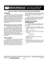
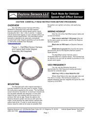
Figure 2 – Typical Dyno Hookup for Multiple <strong>WEGO</strong> <strong>IIID</strong> Systems<br />
BOSCH<br />
LSU 4.2<br />
BOSCH<br />
LSU 4.2<br />
BOSCH<br />
LSU 4.2<br />
BOSCH<br />
LSU 4.2<br />
SENSOR 1 CABLE<br />
IDENTIFIED BY<br />
YELLOW BAND<br />
SENSOR 1 INPUT<br />
SENSOR 2 INPUT<br />
RED<br />
<strong>WEGO</strong> <strong>IIID</strong><br />
HEAVY BLACK<br />
SENSOR 1 INPUT<br />
SENSOR 2 INPUT<br />
RED<br />
<strong>WEGO</strong> <strong>IIID</strong><br />
SENSOR 1 AFR<br />
OUTPUT<br />
SENSOR 2 AFR<br />
OUTPUT<br />
THIN BLACK<br />
SENSOR 1 AFR<br />
OUTPUT<br />
SENSOR 2 AFR<br />
OUTPUT<br />
WHITE<br />
BLUE<br />
WHITE<br />
BLUE<br />
0-5V OUTPUT SCALED:<br />
AFR = 10 + (2 x VOUT)<br />
INPUT<br />
INPUT<br />
INPUT<br />
INPUT<br />
DATA<br />
ACQUISITION<br />
SYSTEM<br />
GROUND<br />
HEAVY BLACK<br />
THIN BLACK<br />
SIGNAL GROUND<br />
13.8 VOLT<br />
POWER<br />
SUPPLY<br />
FILTER<br />
CAPACITOR<br />
POWER GROUND<br />
<strong>Daytona</strong> <strong>Sensors</strong> <strong>LLC</strong>, 933 Beville Road, Suite 101-I, S. <strong>Daytona</strong>, FL 32119 <strong>WEGO</strong> <strong>IIID</strong> 8-<strong>Pack</strong> <strong>Tech</strong> <strong>Note</strong><br />
(386) 322-7390 www.daytona-sensors.com 8/2012<br />
Page 3
DYNO WIRING HOOKUP<br />
For eight channel dyno installations using four<br />
<strong>WEGO</strong> <strong>IIID</strong> systems, you can use the Tenma 72-7670<br />
25 amp power supply available from MCM Electronics<br />
at www.mcmelectronics.com. The Tenma unit is<br />
adjustable from 3-15 volt and should be set to 13.8<br />
volts when used to power <strong>WEGO</strong> units. The power<br />
supply must be located in close proximity to the <strong>WEGO</strong><br />
units. We recommend mounting the <strong>WEGO</strong> units on a<br />
panel next to the dyno data acquisition system and<br />
then running extension cables out to the sensors in the<br />
dyno room.<br />
Refer to Figure 2. For a V8 application with two<br />
banks of two <strong>WEGO</strong> <strong>IIID</strong> units, each bank requires one<br />
of the supplied 12,000 uF 25 volt filter capacitors<br />
(dimensions are 1-3/8”D x 2-1/8”L). Replacement filter<br />
capacitors (P/N 75-36DY123F025AA2A) and mounting<br />
brackets (P/N 539-VR3) are available from Mouser<br />
(phone: 800-346-6873 or www.mouser.com).<br />
For each bank, connect the two <strong>WEGO</strong> <strong>IIID</strong> red<br />
and heavy black wires direct to the filter capacitor<br />
using the supplied #10 ring tongue terminals. Connect<br />
each capacitor+ terminal direct to the power supply<br />
using minimum 16 AWG wire. Connect each capacitorterminal<br />
direct to the power supply and to a good earth<br />
ground using minimum 14 AWG wire. Connect the<br />
<strong>WEGO</strong> <strong>IIID</strong> thin black wires to the same point that the<br />
data acquisition system is grounded. Run an additional<br />
16 AWG ground wire between each capacitor- terminal<br />
and the signal ground point at the data acquisition<br />
system. Keep all power and ground connections as<br />
short as possible. Follow the exact layout shown in<br />
Figure 2. Do not add additional terminal blocks or<br />
connectors to power or ground connections.<br />
<strong>WEGO</strong> POWER REQUIREMENTS<br />
<strong>WEGO</strong> systems are intended for nominal 12 volt<br />
automotive applications. Nominal 12 volt automotive<br />
electrical systems on alternator equipped vehicles<br />
typically operate at 13.8-14.4 volts while the engine is<br />
running. The <strong>WEGO</strong> can operate from 9.0 to 18.0<br />
volts.<br />
Vehicles with nominal 12 volt total loss electrical<br />
systems (no alternator) can momentarily drop below<br />
the 9.0 volt minimum level when heavy loads, such as<br />
fans or nitrous solenoids engage. This will cause the<br />
<strong>WEGO</strong> to reset and result in a loss of data for 10-15<br />
seconds.<br />
Vehicles with nominal 16 volt electrical systems<br />
equipped with race type alternators may reach 18.6<br />
volts while the engine is running. The <strong>WEGO</strong> will shut<br />
off if the voltage exceeds 18.0 volts. Call our tech<br />
support before attempting to install any <strong>WEGO</strong> system<br />
on a nominal 16 volt electrical system with an<br />
alternator.<br />
<strong>Daytona</strong> <strong>Sensors</strong> <strong>LLC</strong>, 933 Beville Road, Suite 101-I, S. <strong>Daytona</strong>, FL 32119 <strong>WEGO</strong> <strong>IIID</strong> 8-<strong>Pack</strong> <strong>Tech</strong> <strong>Note</strong><br />
(386) 322-7390 www.daytona-sensors.com 8/2012<br />
Page 4