WEGO Dynojet® Interface Tech Note - Daytona Sensors LLC
WEGO Dynojet® Interface Tech Note - Daytona Sensors LLC
WEGO Dynojet® Interface Tech Note - Daytona Sensors LLC

Create successful ePaper yourself
Turn your PDF publications into a flip-book with our unique Google optimized e-Paper software.
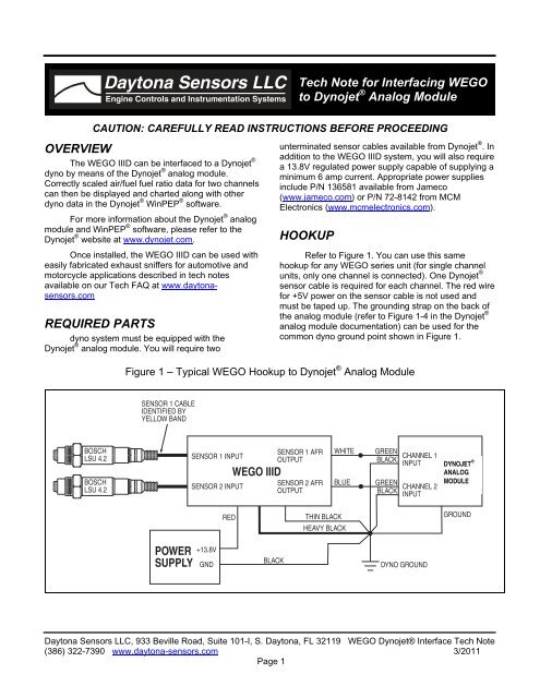
<strong>Daytona</strong> <strong>Sensors</strong> <strong>LLC</strong>Engine Controls and Instrumentation Systems<strong>Tech</strong> <strong>Note</strong> for Interfacing <strong>WEGO</strong>to Dynojet ® Analog ModuleCAUTION: CAREFULLY READ INSTRUCTIONS BEFORE PROCEEDINGOVERVIEWThe <strong>WEGO</strong> IIID can be interfaced to a Dynojet ®dyno by means of the Dynojet ® analog module.Correctly scaled air/fuel fuel ratio data for two channelscan then be displayed and charted along with otherdyno data in the Dynojet ® WinPEP ® software.For more information about the Dynojet ® analogmodule and WinPEP ® software, please refer to theDynojet ® website at www.dynojet.com.Once installed, the <strong>WEGO</strong> IIID can be used witheasily fabricated exhaust sniffers for automotive andmotorcycle applications described in tech notesavailable on our <strong>Tech</strong> FAQ at www.daytonasensors.comREQUIRED PARTSdyno system must be equipped with theDynojet ® analog module. You will require twounterminated sensor cables available from Dynojet ® . Inaddition to the <strong>WEGO</strong> IIID system, you will also requirea 13.8V regulated power supply capable of supplying aminimum 6 amp current. Appropriate power suppliesinclude P/N 136581 available from Jameco(www.jameco.com) or P/N 72-8142 from MCMElectronics (www.mcmelectronics.com).HOOKUPRefer to Figure 1. You can use this samehookup for any <strong>WEGO</strong> series unit (for single channelunits, only one channel is connected). One Dynojet ®sensor cable is required for each channel. The red wirefor +5V power on the sensor cable is not used andmust be taped up. The grounding strap on the back ofthe analog module (refer to Figure 1-4 in the Dynojet ®analog module documentation) can be used for thecommon dyno ground point shown in Figure 1.Figure 1 – Typical <strong>WEGO</strong> Hookup to Dynojet ® Analog ModuleSENSOR 1 CABLEIDENTIFIED BYYELLOW BANDBOSCHLSU 4.2BOSCHLSU 4.2SENSOR 1 INPUTSENSOR 2 INPUT<strong>WEGO</strong> IIIDSENSOR 1 AFROUTPUTSENSOR 2 AFROUTPUTWHITEBLUEGREENBLACKGREENBLACKCHANNEL 1INPUTCHANNEL 2INPUTDYNOJET ®ANALOGMODULEREDTHIN BLACKHEAVY BLACKGROUNDPOWERSUPPLY+13.8VGNDBLACKDYNO GROUND<strong>Daytona</strong> <strong>Sensors</strong> <strong>LLC</strong>, 933 Beville Road, Suite 101-I, S. <strong>Daytona</strong>, FL 32119 <strong>WEGO</strong> Dynojet® <strong>Interface</strong> <strong>Tech</strong> <strong>Note</strong>(386) 322-7390 www.daytona-sensors.com 3/2011Page 1
CONFIGURATIONRefer to the Dynojet ® analog moduledocumentation for details. Select an appropriatedisplay name for each channel, such as Front AFR.Voltage levels are 0V at 10 AFR and 5.0V at 20 AFR.All trademarks on this tech note whetherregistered or not, are the property of theirrespective owners. The authors of thistech note are not sponsored by oraffiliated with any of the third-partytrademark or third-party registeredtrademark owners, and make norepresentations about them, their owners,their products or services.<strong>Daytona</strong> <strong>Sensors</strong> <strong>LLC</strong>, 933 Beville Road, Suite 101-I, S. <strong>Daytona</strong>, FL 32119 <strong>WEGO</strong> Dynojet® <strong>Interface</strong> <strong>Tech</strong> <strong>Note</strong>(386) 322-7390 www.daytona-sensors.com 3/2011Page 2