AS 250 remote control alarm system - Swift Owners Club
AS 250 remote control alarm system - Swift Owners Club
AS 250 remote control alarm system - Swift Owners Club

Create successful ePaper yourself
Turn your PDF publications into a flip-book with our unique Google optimized e-Paper software.
Sargent Electrical Services Ltd. 2006<br />
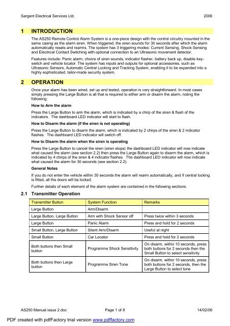
1 INTRODUCTION<br />
The <strong>AS</strong><strong>250</strong> Remote Control Alarm System is a one-piece design with the <strong>control</strong> circuitry mounted in the<br />
same casing as the <strong>alarm</strong> siren. When triggered, the siren sounds for 30 seconds after which the <strong>alarm</strong><br />
automatically resets and rearms. The <strong>system</strong> has 3 triggering modes: Current Sensing, Shock Sensing<br />
and Electrical Contact Switching with optional connection to an Ultrasonic movement detector.<br />
Features include: Panic <strong>alarm</strong>, choice of siren sounds, indicator flasher, battery back up, disable keyswitch<br />
and vehicle locator. The <strong>system</strong> has inputs and outputs for optional accessories, such as<br />
Ultrasonic Sensors, Automatic Central Locking and Tracking System, enabling it to be expanded into a<br />
highly sophisticated, tailor-made security <strong>system</strong>.<br />
2 OPERATION<br />
Once your <strong>alarm</strong> has been wired, set up and tested, operation is very straightforward. In most cases<br />
simply pressing the Large Button is all that is required to either arm or disarm the <strong>alarm</strong>, noting the<br />
following:<br />
How to Arm the <strong>alarm</strong><br />
Press the Large Button to arm the <strong>alarm</strong>, which is indicated by a chirp of the siren & flash of the<br />
indicators. The dashboard LED indicator will start to flash.<br />
How to Disarm the <strong>alarm</strong> (if the siren is not operating)<br />
Press the Large Button to disarm the <strong>alarm</strong>, which is indicated by 2 chirps of the siren & 2 indicator<br />
flashes. The dashboard LED indicator will switch off.<br />
How to Disarm the <strong>alarm</strong> when the siren is operating<br />
Press the Large Button to cancel the siren (siren stops) the dashboard LED indicator will now indicate<br />
what caused the <strong>alarm</strong> (see section 2.2) then press the Large Button again to disarm the <strong>alarm</strong>, which is<br />
indicated by 4 chirps of the siren & 4 indicator flashes. The dashboard LED indicator will now indicate<br />
what caused the <strong>alarm</strong> for 30 seconds (see section 2.2).<br />
General Notes<br />
If you do not enter the vehicle within 30 seconds the <strong>alarm</strong> will rearm automatically, and if central locking<br />
is fitted, all the doors will be locked.<br />
Further details of each element of the <strong>alarm</strong> <strong>system</strong> are contained in the following sections.<br />
2.1 Transmitter Operation<br />
Transmitter Button System Function Remarks<br />
Large Button<br />
Arm/Disarm<br />
Large Button, Large Button Arm with Shock Sensor off Press twice within 3 seconds<br />
Large Button Panic Alarm Press and hold for 2 seconds<br />
Small Button, Large Button Silent Arm/Disarm Useful at night<br />
Small Button Car Locator Press and hold for 2 seconds<br />
Both buttons then Small<br />
button<br />
Both buttons then Large<br />
button<br />
Programme Shock Sensitivity<br />
Programme Siren Tone<br />
On disarm, within 10 seconds, press<br />
both buttons for 2 seconds then the<br />
Small Button to select sensitivity<br />
On disarm, within 10 seconds, press<br />
both buttons for 2 seconds, then the<br />
Large Button to select tone<br />
<strong>AS</strong><strong>250</strong> Manual issue 2.doc Page 1 of 8 14/02/06<br />
PDF created with pdfFactory trial version www.pdffactory.com
Sargent Electrical Services Ltd. 2006<br />
2.2 LED Status Indicator Operation<br />
LED<br />
Off<br />
Slow flashing<br />
Function<br />
Disarmed<br />
Armed<br />
1 Flash ... pause Intrusion on Current Sensor<br />
2 Flashes ... pause Intrusion on Pin Switch / Ultrasonic Movement<br />
3 Flashes ... pause Intrusion on Shock Sensor<br />
2.3 Audible Chirp Indicator<br />
Number of chirps<br />
1 Chirp Arm<br />
Function<br />
2 Chirps Disarm<br />
4 Chirps Disarm after <strong>alarm</strong> has sounded<br />
Note: 4 chirps indicate that the <strong>alarm</strong> is now disarmed, but had been triggered during the armed period<br />
and had reset and rearmed, i.e. the vehicle may have been tampered with.<br />
2.4 Direction Indicator Flash<br />
Number of flashes<br />
1 Flash Arm<br />
Function<br />
2 Flashes Disarm<br />
3 Flashes Disarm after <strong>alarm</strong> has sounded<br />
2.5 Override Key Switch<br />
The key-switch on the back of the <strong>alarm</strong> allows the owner to manually disable and enable the <strong>system</strong>.<br />
This is particularly useful when the vehicle is being serviced, valeted, etc., or if the <strong>remote</strong> key-fob has<br />
been lost (don't keep the override key on the key fob). To enable the <strong>alarm</strong>, turn the override key-switch<br />
to OFF To disable the <strong>alarm</strong> turn the override key-switch to ON. With the override key-switch in the ON<br />
position, the <strong>alarm</strong> will not respond to the key-fob transmitter or any stimulus that would normally set it off.<br />
2.6 Active Arming<br />
With the <strong>alarm</strong> disarmed, press the Large Button on the key fob transmitter. The siren will chirp once, the<br />
Status Indicator will start to flash and the indicators will flash once. After a 3 second delay, the Alarm will<br />
be active.<br />
2.7 Active Disarming<br />
With the <strong>alarm</strong> armed, press the Large Button on the transmitter. The siren will chirp twice, the Status<br />
Indicator will go out and the indicators will flash twice or 3 times to indicate that the <strong>alarm</strong> is disarmed.<br />
Notes:<br />
1 Tamper Disarming. If the <strong>alarm</strong> had been triggered during the time that it was armed, the <strong>alarm</strong> will<br />
chirp 4 times, the indicators will flash 3 times and the Status indicator will flash in a 1, 2, or 3 flash<br />
sequence depending on which sensor was triggered. After 30 seconds or when the ignition switch is<br />
turned on, the Status Indicator will turn off.<br />
2 Automatic Rearming. The <strong>alarm</strong> is equipped with an automatic rearming circuit that will rearm the<br />
<strong>alarm</strong> if a door or the boot or bonnet are not opened within 30 seconds of disarming. This helps to<br />
prevent the <strong>alarm</strong> from accidentally being left disarmed.<br />
<strong>AS</strong><strong>250</strong> Manual issue 2.doc Page 2 of 8 14/02/06<br />
PDF created with pdfFactory trial version www.pdffactory.com
Sargent Electrical Services Ltd. 2006<br />
2.8 Panic Alarm<br />
To manually set off the <strong>alarm</strong> in case of an emergency, e.g., personal attack, press and hold the Large<br />
Button for longer than 3 seconds and the siren will sound and the indicators will flash. To stop the panic<br />
<strong>alarm</strong>, press the Large Button again.<br />
2.9 Vehicle Locator<br />
Forgotten where you parked? Press and hold the Small Button for 2 seconds and the <strong>alarm</strong> will sound<br />
and the indicators will flash to show you where it is.<br />
2.10 Silent Arm and Disarm<br />
To arm or disarm the <strong>alarm</strong> at night, or when the chirps could cause a noise nuisance, press the small<br />
Button and then the Large Button.<br />
2.11 Warn Away Facility<br />
This <strong>system</strong> incorporates a 'Warn Away' facility, which produces a low volume 'chirp' sound if the shock<br />
sensor is triggered, e.g., by an attempted entry. This alone may well be sufficient to deter a thief. (Or, in<br />
the case of an accidental bump, will not inconvenience anyone by setting off the siren). If however, an<br />
intruder persists and the sensor is triggered more than twice, within a 20 second period, the siren will<br />
sound and the indicators will flash as normal.<br />
2.12 Alarm Triggered<br />
After the initial delay from arming the <strong>system</strong>, opening the doors or boot/bonnet, or rocking the vehicle,<br />
will set off the <strong>alarm</strong>. The siren will sound for 30 seconds and then stop. The <strong>alarm</strong> will automatically reset<br />
and rearm. If the shock sensor is continually triggered, e.g., by high winds, the <strong>alarm</strong> will sound and reset<br />
as above a maximum of 3 times. If the shock sensor continues to be triggered, the <strong>alarm</strong> will ignore it until<br />
it ceases to be triggered for a time, i.e., when the wind dies down. After this time the <strong>alarm</strong> will return to<br />
normal operation. This avoids the nuisance of the <strong>alarm</strong> sounding for excessively long periods.<br />
In high winds or areas of high vibration, etc., the shock sensor can be temporarily switched off by<br />
pressing the Large Button to arm the <strong>alarm</strong>, then within 3 seconds, pressing the Large Button again. The<br />
operation of the sensor reverts to normal when the <strong>alarm</strong> is next set.<br />
2.13 Transmitter Battery Replacement<br />
If the range of your transmitter decreases or it fails to operate, the transmitter battery may require<br />
changing.<br />
1 Remove the screw from the back of the transmitter case.<br />
2 Carefully remove the top half of the case.<br />
3 Remove the old battery.<br />
4 Fit a new battery (12V, type 23A) noting the '+' and '-' marks.<br />
5 Replace the top case, taking care not to damage the internal components.<br />
6 Replace and tighten the screw in the back of the transmitter case.<br />
2.14 Fuse Replacement<br />
Two blade-type fuses are fitted in the wiring of the <strong>alarm</strong>. The red power lead is fitted with a fuse rated at<br />
5A. If this fuse blows, all <strong>alarm</strong> functions will be lost. The red/white wire is fitted with a fuse rated at 10A. If<br />
this fuse blows, the indicator flashing facility will be lost but all other <strong>alarm</strong> functions will continue to work.<br />
When replacing fuses, you must ONLY USE REPLACEMENT FUSES OF THE SAME RATING.<br />
Replacement fuses are widely available from car accessory shops or from your dealer.<br />
<strong>AS</strong><strong>250</strong> Manual issue 2.doc Page 3 of 8 14/02/06<br />
PDF created with pdfFactory trial version www.pdffactory.com
Sargent Electrical Services Ltd. 2006<br />
3 PROGRAMMING AND ADJUSTMENTS<br />
Note: You MUST program the transmitter codes before proceeding with any adjustments. Ensure that the<br />
key switch located under the rubber cap on the back of the <strong>AS</strong><strong>250</strong> is set to OFF.<br />
<strong>AS</strong><strong>250</strong> KEY FOB<br />
3.1 Programming the Transmitter Codes<br />
Note: The <strong>AS</strong><strong>250</strong> can learn the codes of up to two transmitters, allowing a second transmitter to be used<br />
as a spare or by a second user of the vehicle.<br />
1 DOUBLE-CHECK THE WIRING and reconnect the vehicle battery.<br />
2 Disconnect the back-up battery, if fitted.<br />
3 Reset the <strong>AS</strong><strong>250</strong> by disconnecting the 9-way connector, wait 10 seconds, and then reconnect.<br />
4 Press the Large button of the transmitter and hold it down until you hear a chirp from the siren, then<br />
release the button.<br />
5 If you have a SECOND transmitter, within 5 seconds, press the large button of the SECOND<br />
transmitter and hold it down until you hear 1 or 2 chirps from the siren, then release the button.<br />
6 Reconnect the back-up battery, if fitted.<br />
Notes:<br />
• After programming the FIRST transmitter code, the <strong>AS</strong><strong>250</strong> waits for 5 seconds to allow you to<br />
programme the SECOND transmitter. If the <strong>AS</strong><strong>250</strong> does not receive another transmitter code<br />
within those 5 seconds it automatically exits the programming mode.<br />
• Should you wish to reprogram the transmitter codes, repeat steps 1 to 6 above.<br />
3.2 Shock Sensor Testing and Adjustments<br />
On disarming the <strong>alarm</strong>, the shock sensor sensitivity can be adjusted to suit your requirements. Proceed<br />
as follows:<br />
1 Arm the <strong>alarm</strong> by pressing the large button once. The <strong>alarm</strong> will chirp once to confirm setting.<br />
2 Disarm the <strong>alarm</strong> by pressing the large button again. The <strong>alarm</strong> will chirp twice to confirm disarming.<br />
3 Within 10 seconds, press and hold both buttons for 2 seconds. The <strong>alarm</strong> will chirp once to confirm<br />
that it is now in programming mode.<br />
4 By repeatedly pressing the small button, you can select one of 8 sensitivity levels as indicated by<br />
corresponding tones. The higher the pitch of the tone, the more sensitive the <strong>alarm</strong> is to shock.<br />
5 Hit the vehicle with your palm to simulate an intrusion.<br />
6 The <strong>alarm</strong> produces a single chirp sound if the shock sensor is only gently triggered, and a ding-dong<br />
sound if the shock sensor is heavily triggered.<br />
7 Adjust the sensitivity of the sensor, either up or down, by pressing the small button. The ideal setting<br />
is when a gentle bump produces the chirp sound, but a heavy bump, e.g., kicking a tyre, produces the<br />
ding-dong sound.<br />
<strong>AS</strong><strong>250</strong> Manual issue 2.doc Page 4 of 8 14/02/06<br />
PDF created with pdfFactory trial version www.pdffactory.com
Sargent Electrical Services Ltd. 2006<br />
8 When you are satisfied with the setting, press the large button to exit programming mode. The-<strong>alarm</strong><br />
will chirp twice to confirm exit. The <strong>alarm</strong> will also exit automatically if no buttons are pressed within<br />
10 seconds.<br />
NOTE: DO NOT SET THE SENSITIVITY TOO HIGH <strong>AS</strong> THIS MAY RESULT IN FALSE ALARMS,<br />
ADJUST THE SENSITIVITY TO THE MINIMUM THAT WILL PROTECT YOUR VEHICLE.<br />
3.3 Siren Tone Selection<br />
A choice of 5 different siren tones and a multi-tone can be selected. Proceed as follows:<br />
1 Arm the <strong>alarm</strong> by pressing the large button once. The <strong>alarm</strong> will chirp once to confirm setting.<br />
2 Disarm the <strong>alarm</strong> by pressing the large button again. The <strong>alarm</strong> will chirp twice to confirm disarming.<br />
3 Within 10 seconds, press and hold both buttons for 2 seconds. The <strong>alarm</strong> will chirp once to confirm<br />
that it is now in programming mode.<br />
4 By repeatedly pressing the large button, you can select one of 5 siren tones or the multitone.<br />
5 The last tone produced is the one that will be stored. When you have selected a tone, press the small<br />
button to exit programming mode. The <strong>alarm</strong> will chirp twice to confirm exit. The <strong>alarm</strong> will also exit<br />
automatically if no buttons are pressed within 10 seconds.<br />
<strong>AS</strong><strong>250</strong> Manual issue 2.doc Page 5 of 8 14/02/06<br />
PDF created with pdfFactory trial version www.pdffactory.com
Sargent Electrical Services Ltd. 2006<br />
4 INSTALLATION<br />
PLE<strong>AS</strong>E READ THIS INSTRUCTION MANUAL COMPLETELY BEFORE COMMENCING<br />
INSTALLATION.<br />
CAUTION: DO NOT CONNECT THE SYSTEM TO THE VEHICLE'S POWER SUPPLY UNTIL ALL<br />
WIRING IS COMPLETE AND CHECKED. THIS ALARM CAN ONLY BE USED ON NEGATIVE EARTH<br />
VEHICLES<br />
Disconnect the vehicle battery before commencing any wiring and ensure that wiring is kept away from:<br />
• Moving parts such as cooling fans and <strong>control</strong> linkages, etc.<br />
• Heat such as from the exhaust manifold and pipes.<br />
• High voltage cables such as spark plug leads.<br />
Secure the wires to the car body or wiring harness at regular intervals, using cable ties or tape. Where<br />
possible, route wires under carpets or trim to give a neat finish and to prevent accidental damage during<br />
cleaning and maintenance activities. To prevent cables being cut by sharp metal edges and causing a<br />
short circuit, ensure that all cables passing through holes in metal panels are protected by rubber<br />
grommets or insulating tape.<br />
TOOLS REQUIRED:<br />
Terminal crimper, Electric drill, Pliers, Philips screwdriver, Voltmeter/Tester, Electrical insulating tape,<br />
Wire cutter, 11mm socket, Wire stripper, 5mm 6mm 7mm 8mm Drill bits.<br />
4.1 Mounting the Alarm System<br />
1 Mount the <strong>AS</strong><strong>250</strong> in the engine compartment and, if possible, facing the front of the vehicle in order to<br />
obtain best sound results. Do not mount the <strong>AS</strong><strong>250</strong> 'face up' or near heat sources such as the<br />
exhaust manifold. Choose a position, which will not expose the <strong>AS</strong><strong>250</strong> to excessive moisture, and<br />
allows easy connection of wiring.<br />
2 Using the mounting bracket as a template, mark the position of the fixing holes. Using a 5mm bit, drill<br />
out the holes being careful not to damage any wires, pipes, etc., which may be beneath the panel you<br />
are drilling. Fix the bracket to the vehicle using the self-tapping screws, washers and lock-washers<br />
provided.<br />
3 Mount the <strong>AS</strong><strong>250</strong> on the bracket and fasten it with the bolts, washers and lock washers provided.<br />
Adjust the unit to the correct angle and tighten the bolts.<br />
4.2 Installing the LED Status Indicator<br />
The LED Status Indicator should be mounted in a highly visible area such as the top of the dashboard,<br />
the steering column cover or the face of the dashboard. There must be at least 16mm clearance behind<br />
the mounting position to accommodate the LED housing. When a suitable position has been found, drill a<br />
8mm hole, taking care not to damage any wiring, etc., beneath the panel you are drilling. Feed the LED<br />
wires through the hole and through the bulkhead into the engine compartment and then to the <strong>AS</strong><strong>250</strong>.<br />
Push-fit the indicator into the mounting hole.<br />
4.3 Installing Bonnet / Boot Pin Switches<br />
Select a suitable position for the Pin Switches. This will probably be in the channel that the bonnet/boot<br />
closes into, as it must be operated by the closure of the bonnet/boot. For the boot, use the gold, fully<br />
adjustable Pin Switch provided. Drill a 7mm hole, taking care not to damage wires and pipes, etc., which<br />
may be beneath the panel you are drilling, and mount the Pin Switch at a depth at which it is operated by<br />
the closed boot. For the bonnet, use the silver, non-adjustable, Pin Switch. Drill a 6mm hole and use an<br />
11 mm socket to self-tap the Pin Switch into position.<br />
Notes:<br />
• The Pin Switch mountings must provide a good electrical connection to the chassis.<br />
• If boot/bonnet lights are fitted to your vehicle and the <strong>alarm</strong> is used in Current Sensing mode,<br />
the <strong>alarm</strong> will be set off by the boot/bonnet light switching on. It is therefore not essential, in this<br />
case, that the pin switches are fitted.<br />
<strong>AS</strong><strong>250</strong> Manual issue 2.doc Page 6 of 8 14/02/06<br />
PDF created with pdfFactory trial version www.pdffactory.com
Sargent Electrical Services Ltd. 2006<br />
4.4 Installing the Back-up Battery<br />
Undo the two retaining screws and remove the battery storage compartment cover. Clip the battery<br />
connector to a PP3 size battery and place it in the battery storage compartment. Connect the 2-pin socket<br />
on the other end of the battery connector to the 2-pin plug on the <strong>alarm</strong>, noting that the socket only fits<br />
one way round. Position the cover the right way round and secure it with the retaining screws. The battery<br />
must be a quality alkaline long life battery, and should be replaced annually.<br />
4.5 Fitting the Decals<br />
Ensure that the area of window / windscreen that you intend to place the decal on is clean, dry and free<br />
from oil or grease. Simply peel the decal from the backing paper and apply to the inside of the<br />
window/windscreen. The decal alone can be an effective deterrent to a would-be thief.<br />
4.6 Main 9-Way Connector<br />
• RED WIRE: System Power - Constant 12V input. The red wire incorporates a 5A fuse, and is<br />
supplied already connected to the red/white wire (paragraph 7). Locate the cable on the vehicle<br />
that feeds power to the fuse, which protects the interior courtesy light; check that this connection<br />
is capable of supplying at least 10A. Refer to the vehicle-wiring diagram if necessary. Connect<br />
the red wire from the <strong>alarm</strong> as close as possible to the fuse end of the cable, e.g., on the fuse<br />
holder connector. If the connection is made too close to the battery end of the cable, the Current<br />
Sensing mode may not function properly. (If the Current Sensing mode is not going to be used,<br />
then this connection should be made as close as possible to the battery end of the cable.)<br />
• BLACK WIRE: System Ground. This is the Negative or Ground connection of the <strong>AS</strong><strong>250</strong>. A<br />
good electrical connection to the vehicle body is essential for correct operation. Do not connect it<br />
to any existing Ground wires, instead secure it directly to the vehicle's metalwork with a nut and<br />
bolt (not a screw).<br />
• YELLOW WIRES: Ignition Disable. Locate the wire coming from the ignition key-switch that<br />
supplies power to the ignition coil, if necessary refer to the vehicle handbook. With the vehicle<br />
battery disconnected, cut the cable so as to leave both ends accessible. To check that you have<br />
the correct wire, reconnect the vehicle battery and attempt to start the car. (Handbrake on,<br />
select neutral.) The starter should turn but the engine should not start. Disconnect the vehicle<br />
battery. Connect one of the yellow wires to each end of the cut wire. If these wires are not going<br />
to be used, tape the ends, coil up and secure for possible future use.<br />
• BLACK/WHITE WIRE: LED Status Indicator Connection. Connect this wire to the black wire of<br />
the LED Status Indicator. Connect the red wire of the indicator to a constant 12V supply.<br />
• ORANGE WIRE: Grounded output when armed. This output has a current capacity of 500mA,<br />
and becomes grounded when the Alarm is armed. It is used to <strong>control</strong> optional accessories such<br />
as automatic central locking, automatic electric window close, starter interrupt, etc., which<br />
operate when the Alarm is armed. See Additional Accessories.<br />
• RED/WHITE WIRE: Indicator Flash Power Input. This wire supplies power to the <strong>alarm</strong> for the<br />
Indicator Flash Outputs and incorporates a l0A fuse. This wire is already connected to the red<br />
wire (paragraph 1).<br />
• WHITE WIRES: Indicator Flash Outputs. When the Alarm is triggered, these wires each provide<br />
a pulsed 12V, 5A output to flash the vehicle's indicator lights. Connect one wire to the switched<br />
side of the left indicator circuit and the other to the switched side of the right indicator circuit. The<br />
total wattage of bulbs connected to each output must not exceed 60W.<br />
4.7 2-Way Connector<br />
• BLUE WIRE: Ground trigger input. This is the wire that connects to the boot and bonnet Pin<br />
Switches if you have chosen to fit them. Make the connections using the crimp-on bullet<br />
connectors supplied, which push into the base of the Pin Switch. Connect both switches to the<br />
blue wire. This is also the input to which additional Ground Output sensors, such as ultrasonic<br />
detectors, may be connected. See the instructions supplied with the Additional Accessories<br />
described later in this manual. If this wire is not going to be used, tape the end, coil up and<br />
secure for possible future use.<br />
• VIOLET WIRE: Current Sensing Circuit <strong>control</strong>. Some cars are fitted with electric cooling fans,<br />
which operate for a short period after the ignition is switched off. This could cause the Current<br />
<strong>AS</strong><strong>250</strong> Manual issue 2.doc Page 7 of 8 14/02/06<br />
PDF created with pdfFactory trial version www.pdffactory.com
Sargent Electrical Services Ltd. 2006<br />
Sensing Circuit to trigger if the Alarm is armed immediately after the ignition is turned off,<br />
resulting in a false <strong>alarm</strong>. If your vehicle has such a fan, connect the violet wire as follows. If<br />
your vehicle does not have such a fan, tape the end, coil up and secure for possible future use.<br />
Consult the vehicle-wiring diagram if necessary, and locate the switched positive wire to the<br />
vehicle's electric fan relay. The wire required is at 1 2V when the fan is running and at OV when<br />
the fan is not running. Connect the violet wire to the switched positive wire.<br />
Note: To completely disable the Current Sensing facility if it is not required, connect the violet<br />
wire to a point as close as possible to the positive side of the battery. The battery terminal itself<br />
could be used or the other end of the thick cable from the battery to the starter solenoid, where<br />
there may be a more suitable connection point. Instead, protect the vehicle by using Pin<br />
Switches on the doors, boot and bonnet, connected to the blue wire.<br />
4.8 Thin Black Wire: RF Antenna<br />
This is the receiver's RF antenna or aerial and MUST be FULLY extended as straight as possible, angled<br />
AWAY from the chassis or large metal objects. If poor range is encountered, try different antenna<br />
positions. When satisfactory, secure it in position with cable ties or tape. Do not shorten or extend this<br />
wire, as this may adversely affect the operation of the receiver. The antenna MUST NOT be connected to<br />
either Ground or the 12V supply. Tape the end of this wire, if necessary, to prevent short circuits.<br />
5 ADDITIONAL ACCESSORIES AVAILABILITY<br />
5.1 Power lock Door Interface<br />
When added to the <strong>system</strong>, this interface will automatically operate the vehicle's central locking <strong>system</strong> (if<br />
fitted), locking the doors when the Alarm is armed and unlocking them when the Alarm is disarmed.<br />
5.2 Spare/Second Key Fob Transmitter<br />
Two button key fob transmitters are available either as replacement or for a second user of the vehicle.<br />
See programming instructions for further details.<br />
5.3 Ultrasonic Movement Detector<br />
CS-18S ultrasonic sensor<br />
Operation voltage range: 8v - 18v DC, Quiescent current: 3ma - 5ma<br />
Detecting range: 0.5m - 3m (adjustable), Output drain: 100ma (max)<br />
Output pulse width: negative pulse about 0.8s-1.2s<br />
Installation notes:<br />
Ultrasonic cells should be placed on the left and right side as high as possible so as to obtain the best<br />
performance. Placing the cells on the same side will reduce the sensitivity.<br />
5.4 Garage Door Module<br />
A receiver module that can use the same key fob transmitter as your <strong>alarm</strong> and is ideal for garage door<br />
opening and <strong>remote</strong> light switching.<br />
For prices and availability of accessories, contact Sargent Electrical Services Ltd. on 01482 881655.<br />
<strong>AS</strong><strong>250</strong> Manual issue 2.doc Page 8 of 8 14/02/06<br />
PDF created with pdfFactory trial version www.pdffactory.com