AS 250 remote control alarm system - Swift Owners Club
AS 250 remote control alarm system - Swift Owners Club
AS 250 remote control alarm system - Swift Owners Club
You also want an ePaper? Increase the reach of your titles
YUMPU automatically turns print PDFs into web optimized ePapers that Google loves.
Sargent Electrical Services Ltd. 2006<br />
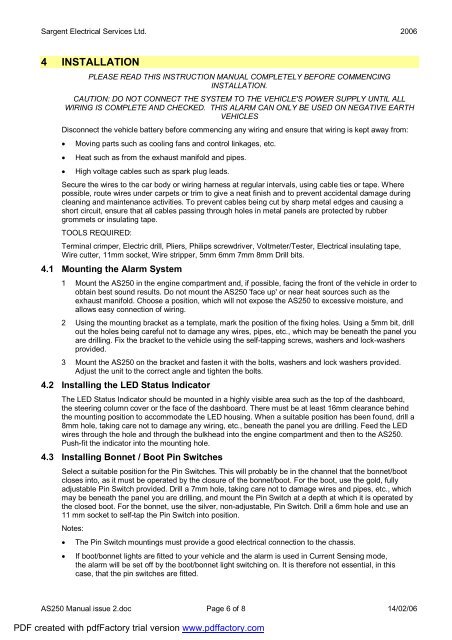
4 INSTALLATION<br />
PLE<strong>AS</strong>E READ THIS INSTRUCTION MANUAL COMPLETELY BEFORE COMMENCING<br />
INSTALLATION.<br />
CAUTION: DO NOT CONNECT THE SYSTEM TO THE VEHICLE'S POWER SUPPLY UNTIL ALL<br />
WIRING IS COMPLETE AND CHECKED. THIS ALARM CAN ONLY BE USED ON NEGATIVE EARTH<br />
VEHICLES<br />
Disconnect the vehicle battery before commencing any wiring and ensure that wiring is kept away from:<br />
• Moving parts such as cooling fans and <strong>control</strong> linkages, etc.<br />
• Heat such as from the exhaust manifold and pipes.<br />
• High voltage cables such as spark plug leads.<br />
Secure the wires to the car body or wiring harness at regular intervals, using cable ties or tape. Where<br />
possible, route wires under carpets or trim to give a neat finish and to prevent accidental damage during<br />
cleaning and maintenance activities. To prevent cables being cut by sharp metal edges and causing a<br />
short circuit, ensure that all cables passing through holes in metal panels are protected by rubber<br />
grommets or insulating tape.<br />
TOOLS REQUIRED:<br />
Terminal crimper, Electric drill, Pliers, Philips screwdriver, Voltmeter/Tester, Electrical insulating tape,<br />
Wire cutter, 11mm socket, Wire stripper, 5mm 6mm 7mm 8mm Drill bits.<br />
4.1 Mounting the Alarm System<br />
1 Mount the <strong>AS</strong><strong>250</strong> in the engine compartment and, if possible, facing the front of the vehicle in order to<br />
obtain best sound results. Do not mount the <strong>AS</strong><strong>250</strong> 'face up' or near heat sources such as the<br />
exhaust manifold. Choose a position, which will not expose the <strong>AS</strong><strong>250</strong> to excessive moisture, and<br />
allows easy connection of wiring.<br />
2 Using the mounting bracket as a template, mark the position of the fixing holes. Using a 5mm bit, drill<br />
out the holes being careful not to damage any wires, pipes, etc., which may be beneath the panel you<br />
are drilling. Fix the bracket to the vehicle using the self-tapping screws, washers and lock-washers<br />
provided.<br />
3 Mount the <strong>AS</strong><strong>250</strong> on the bracket and fasten it with the bolts, washers and lock washers provided.<br />
Adjust the unit to the correct angle and tighten the bolts.<br />
4.2 Installing the LED Status Indicator<br />
The LED Status Indicator should be mounted in a highly visible area such as the top of the dashboard,<br />
the steering column cover or the face of the dashboard. There must be at least 16mm clearance behind<br />
the mounting position to accommodate the LED housing. When a suitable position has been found, drill a<br />
8mm hole, taking care not to damage any wiring, etc., beneath the panel you are drilling. Feed the LED<br />
wires through the hole and through the bulkhead into the engine compartment and then to the <strong>AS</strong><strong>250</strong>.<br />
Push-fit the indicator into the mounting hole.<br />
4.3 Installing Bonnet / Boot Pin Switches<br />
Select a suitable position for the Pin Switches. This will probably be in the channel that the bonnet/boot<br />
closes into, as it must be operated by the closure of the bonnet/boot. For the boot, use the gold, fully<br />
adjustable Pin Switch provided. Drill a 7mm hole, taking care not to damage wires and pipes, etc., which<br />
may be beneath the panel you are drilling, and mount the Pin Switch at a depth at which it is operated by<br />
the closed boot. For the bonnet, use the silver, non-adjustable, Pin Switch. Drill a 6mm hole and use an<br />
11 mm socket to self-tap the Pin Switch into position.<br />
Notes:<br />
• The Pin Switch mountings must provide a good electrical connection to the chassis.<br />
• If boot/bonnet lights are fitted to your vehicle and the <strong>alarm</strong> is used in Current Sensing mode,<br />
the <strong>alarm</strong> will be set off by the boot/bonnet light switching on. It is therefore not essential, in this<br />
case, that the pin switches are fitted.<br />
<strong>AS</strong><strong>250</strong> Manual issue 2.doc Page 6 of 8 14/02/06<br />
PDF created with pdfFactory trial version www.pdffactory.com


