Specalog for AccuGrade® Grade Control System for Motor Graders ...
Specalog for AccuGrade® Grade Control System for Motor Graders ...
Specalog for AccuGrade® Grade Control System for Motor Graders ...

You also want an ePaper? Increase the reach of your titles
YUMPU automatically turns print PDFs into web optimized ePapers that Google loves.
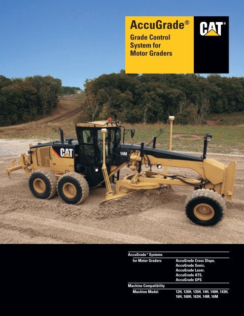
Accu<strong>Grade</strong> ®<br />
<strong>Grade</strong> <strong>Control</strong><br />
<strong>System</strong> <strong>for</strong><br />
<strong>Motor</strong> <strong>Grade</strong>rs<br />
®<br />
Accu<strong>Grade</strong> ® <strong>System</strong>s<br />
<strong>for</strong> <strong>Motor</strong> <strong>Grade</strong>rs Accu<strong>Grade</strong> Cross Slope,<br />
Accu<strong>Grade</strong> Sonic,<br />
Accu<strong>Grade</strong> Laser,<br />
Accu<strong>Grade</strong> ATS,<br />
Accu<strong>Grade</strong> GPS<br />
Machine Compatibility<br />
Machine Model 12H, 120H, 135H, 14H, 140H, 143H,<br />
16H, 160H, 163H, 14M, 16M
Accu<strong>Grade</strong> ® <strong>Grade</strong> <strong>Control</strong> <strong>System</strong> <strong>for</strong> <strong>Motor</strong> <strong>Grade</strong>rs<br />
Accu<strong>Grade</strong> <strong>Grade</strong> <strong>Control</strong> <strong>System</strong>s simplify grading, improve accuracy, increase productivity,<br />
minimize material usage, and lower operating costs.<br />
Accu<strong>Grade</strong> ® Attachment Ready Option<br />
(ARO) Machine<br />
The Accu<strong>Grade</strong> ARO machine simplifies<br />
system installation and reduces machine<br />
downtime. The Accu<strong>Grade</strong> system is<br />
designed and integrated into the machine<br />
systems and controls to optimize<br />
per<strong>for</strong>mance and reliability. pg. 4<br />
Accu<strong>Grade</strong> ® Cross Slope<br />
The Cross Slope <strong>System</strong> uses three<br />
machine-mounted sensors to calculate<br />
cross slope of the blade. The system<br />
combines automated controls with<br />
manual elevation adjustments to<br />
achieve desired cross slope. pg. 6<br />
Accu<strong>Grade</strong> ® Sonic<br />
The Sonic <strong>System</strong> uses ultrasonic sound<br />
waves and a sonic elevation sensor to<br />
measure distance and calculate elevation.<br />
The system features automated blade<br />
adjustments <strong>for</strong> automatic elevation<br />
control and built-in vertical guidance<br />
indicators <strong>for</strong> manual control. pg. 7<br />
Features and Benefits<br />
Accu<strong>Grade</strong> delivers a wide range of<br />
customer benefits designed to: increase<br />
operator efficiency and productivity,<br />
improve accuracy, reduce material<br />
costs, reduce surveying and labor costs,<br />
and lower overall operating costs.<br />
pg. 14<br />
Fine grade with greater accuracy and<br />
control with Accu<strong>Grade</strong> technology solutions<br />
<strong>for</strong> motor graders. Accu<strong>Grade</strong> begins with the<br />
basic cross slope system. <strong>System</strong> flexibility<br />
allows elevation control to be combined with<br />
cross slope control to meet a wide range of<br />
site-specific grade requirements.<br />
• Accu<strong>Grade</strong> Cross Slope – cross slope control<br />
• Accu<strong>Grade</strong> Sonic – 2D elevation control<br />
• Accu<strong>Grade</strong> Laser – 2D elevation control<br />
• Accu<strong>Grade</strong> ATS – 3D elevation control<br />
• Accu<strong>Grade</strong> GPS – 3D elevation control<br />
2
Accu<strong>Grade</strong> ® Laser<br />
The Laser <strong>System</strong> leverages laser<br />
technology to create an accurate grade<br />
elevation reference over the work area.<br />
The system features automated blade<br />
adjustments <strong>for</strong> elevation control with<br />
tight tolerances and built-in elevation/<br />
grade display indicators <strong>for</strong> manual<br />
control. pg. 8<br />
Accu<strong>Grade</strong> ® ATS<br />
The ATS <strong>System</strong> uses an Advanced<br />
Tracking Sensor (ATS) with target<br />
recognition to track a machine and<br />
determine precise blade positioning.<br />
The system features fully automated<br />
blade adjustments <strong>for</strong> automatic<br />
elevation control. pg. 10<br />
Accu<strong>Grade</strong> ® GPS<br />
The GPS <strong>System</strong> uses Global Positioning<br />
<strong>System</strong> (GPS) satellites to determine<br />
precise blade positioning. The system<br />
features fully automated blade<br />
adjustments <strong>for</strong> automatic elevation<br />
control, and vertical and horizontal<br />
guidance light bars <strong>for</strong> manual control.<br />
pg. 12<br />
✔ New Feature<br />
3
Accu<strong>Grade</strong> ® Attachment Ready Option (ARO) Machine<br />
The Accu<strong>Grade</strong> ARO machine integrates the Accu<strong>Grade</strong> system into the machine systems<br />
and controls to optimize per<strong>for</strong>mance, reliability and productivity.<br />
Accu<strong>Grade</strong> <strong>for</strong> <strong>Motor</strong> <strong>Grade</strong>rs.<br />
Caterpillar is helping customers<br />
revolutionize the way they move<br />
material with new technology solutions<br />
<strong>for</strong> earthmoving machines. Solutions<br />
that provide greater accuracy, higher<br />
productivity, lower operating costs,<br />
and more profitability.<br />
The Accu<strong>Grade</strong> <strong>System</strong> is designed<br />
and integrated into the machine and<br />
hydraulic systems to create an automatic<br />
blade control system that allows operators<br />
to grade with complete accuracy.<br />
The system uses intelligent, machinemounted<br />
sensors to calculate precise<br />
blade slope and elevation in<strong>for</strong>mation.<br />
The integrated electrohydraulic valve<br />
control module uses in<strong>for</strong>mation received<br />
from the sensors to make automatic<br />
adjustments to the blade. Depending<br />
on the configuration of the Accu<strong>Grade</strong><br />
elevation control system (single or dual<br />
control), the system allows the operator<br />
to select which side of the blade to<br />
control – right, left, or both sides.<br />
Automatic blade control allows operators<br />
to improve efficiency and productivity<br />
by achieving grade faster and in fewer<br />
passes than ever be<strong>for</strong>e, reducing the<br />
need <strong>for</strong> traditional survey stakes or<br />
grade checkers.<br />
Accu<strong>Grade</strong> Attachment Ready Option<br />
(ARO) Machine. The factory Accu<strong>Grade</strong><br />
ARO machine makes system installation<br />
and setup quick and easy and optimizes<br />
per<strong>for</strong>mance and reliability.<br />
• Hydraulic control systems are<br />
integrated into the machine<br />
hydraulics <strong>for</strong> maximum per<strong>for</strong>mance<br />
and dependability.<br />
• Accu<strong>Grade</strong> controls are integrated<br />
into the machine controls and<br />
levers <strong>for</strong> reliable operation and<br />
precise control.<br />
• A valve control module delivers<br />
precise, automatic control of the<br />
blade functions.<br />
• A power module provides clean,<br />
filtered DC power to all system<br />
components.<br />
• Wiring harnesses and cables are<br />
routed during assembly <strong>for</strong> improved<br />
wear protection and better reliability.<br />
• <strong>System</strong> is designed to withstand<br />
vibration <strong>for</strong> long life in rugged<br />
working environments.<br />
• Safety interlock feature is built<br />
in <strong>for</strong> added protection during<br />
automated operation.<br />
4
Plug and Play Capability. The system<br />
uses a <strong>Control</strong>ler Area Network (CAN)<br />
designed <strong>for</strong> plug-and-play capability.<br />
This allows components to be quickly<br />
and easily added or removed. Common<br />
connectors provide a flexible system,<br />
fully upgradeable from single cross<br />
slope to dual elevation control. Moving<br />
the add-on systems from one machine<br />
to another is easy. Simply mount the<br />
components, connect, calibrate, and the<br />
system is ready to operate.<br />
Applications. The Accu<strong>Grade</strong> ® system<br />
is designed <strong>for</strong> a wide range of<br />
construction earthwork applications,<br />
from bulk earth moving with high<br />
production rates to finish grading with<br />
tight tolerances. Field-proven and<br />
versatile, the two-dimensional grade<br />
control systems are ideal <strong>for</strong> fine grading<br />
of roads requiring precise crown work,<br />
and sites with flat surfaces, single slopes<br />
and dual slopes, such as building pads,<br />
parking lots, roads and highways.<br />
The three-dimensional systems are ideal<br />
<strong>for</strong> complex 3D designs, such as golf<br />
courses and roads with superelevations.<br />
<strong>System</strong> Flexibility. The basic system<br />
provides cross slope control. The operator<br />
selects which side of the blade to<br />
activate <strong>for</strong> automatic control and<br />
controls elevation manually.<br />
When combined with Accu<strong>Grade</strong><br />
elevation control technologies, the<br />
system provides automatic elevation<br />
control to one or both sides of the blade.<br />
The operator can choose any combination<br />
of control to meet specific job<br />
requirements.<br />
• Cross Slope<br />
• Laser/Cross Slope<br />
• Dual Laser<br />
• Sonic/Cross Slope<br />
• Dual Sonic<br />
• Sonic/Laser<br />
• GPS/Cross Slope<br />
• Dual GPS<br />
• ATS/Cross Slope<br />
Accu<strong>Grade</strong> Technologies.<br />
• Accu<strong>Grade</strong> Cross Slope – 2D cross<br />
slope control<br />
• Accu<strong>Grade</strong> Sonic – single or dual,<br />
2D elevation control<br />
• Accu<strong>Grade</strong> Laser – single or dual,<br />
2D elevation control<br />
• Accu<strong>Grade</strong> GPS – single or dual,<br />
3D elevation control<br />
• Accu<strong>Grade</strong> ATS – dual,<br />
3D elevation control<br />
5
Accu<strong>Grade</strong> ® Cross Slope<br />
Combines automated controls with manual adjustments to achieve desired cross slope.<br />
Operation. Accu<strong>Grade</strong> Cross Slope is<br />
a grade control system designed to<br />
control surface cross slope. Machinemounted<br />
sensors are used to calculate<br />
necessary blade slope positioning to<br />
achieve desired cross slope of the<br />
surface. The system makes automatic<br />
adjustments to the left or right lift<br />
cylinder, typically per<strong>for</strong>med by the<br />
operator. The in-cab display delivers<br />
all of the Accu<strong>Grade</strong> Cross Slope<br />
in<strong>for</strong>mation the operator needs to<br />
quickly and easily spread or cut<br />
material at the correct cross slope.<br />
The operator can select which side of<br />
the blade to control automatically and<br />
swap direction on the return pass without<br />
readjusting the settings. Elevation is<br />
controlled manually by matching grade,<br />
or automatically by adding an elevation<br />
control device.<br />
Cross Slope with Elevation <strong>Control</strong>.<br />
Accu<strong>Grade</strong> Cross Slope can be combined<br />
with one or more of the Accu<strong>Grade</strong><br />
elevation control technologies, such as<br />
Accu<strong>Grade</strong> Sonic, Accu<strong>Grade</strong> Laser,<br />
Accu<strong>Grade</strong> GPS, or Accu<strong>Grade</strong> ATS<br />
<strong>for</strong> automatic control of elevation and<br />
cross slope.<br />
Machine-Mounted Sensors. Accu<strong>Grade</strong><br />
Cross Slope uses three machine-mounted<br />
sensors – a blade slope sensor, mainfall<br />
sensor, and rotation sensor – to calculate<br />
necessary blade adjustments to achieve<br />
desired cross slope of the surface<br />
perpendicular to the direction of travel.<br />
• Blade Slope Angle Sensor. The blade<br />
slope angle sensor is mounted at the<br />
back of the circle. It is used to measure<br />
the slope of the blade.<br />
• Mainfall Sensor. The mainfall sensor<br />
is mounted to the machine frame or<br />
chassis. It measures pitch of the machine,<br />
which is used to calculate the cross<br />
slope. This is the same type of sensor<br />
used to measure blade slope angle.<br />
• Blade Rotation Sensor. The rotation<br />
sensor is mounted on the hydraulic<br />
hydra-valve swivel and measures circle<br />
rotation or blade rotation to calculate<br />
cross slope.<br />
<strong>System</strong> Accuracy. The cross slope<br />
system offers selectable accuracies <strong>for</strong><br />
matching tolerances to specific grade<br />
and application requirements.<br />
Applications.<br />
• New road construction<br />
• Road maintenance<br />
• Road ditches<br />
• Embankments<br />
• Sports fields<br />
Cross Slope <strong>System</strong>. The basic cross<br />
slope system automatically controls the<br />
slope of the blade to maintain desired<br />
surface cross slope.<br />
6
Accu<strong>Grade</strong> ® Sonic<br />
Ultrasonic sound waves calculate elevation from a physical reference point,<br />
such as a stringline, curb or gutter, to maintain elevation.<br />
Operation. Accu<strong>Grade</strong> Sonic is a grade<br />
control system designed to control<br />
surface elevation. The sonic system<br />
uses an ultrasonic sensor to maintain<br />
the blade at the same relative vertical<br />
distance to an external reference, such<br />
as a string line or curb and gutter.<br />
The system makes automatic elevation<br />
adjustments typically per<strong>for</strong>med by the<br />
operator. The operator simply steers the<br />
machine to maintain the sensor over the<br />
external reference.<br />
Single Sonic <strong>System</strong>. When combined<br />
with Accu<strong>Grade</strong> Cross Slope, the single<br />
system provides automatic blade<br />
adjustments to one side of the blade<br />
<strong>for</strong> automatic control of elevation and<br />
cross slope.<br />
Dual Sonic <strong>System</strong>. When two sonic<br />
sensors are used, the system provides<br />
automatic elevation control to either<br />
side of the blade. The system typically<br />
uses only one sensor at a time. This<br />
allows the operator to control which<br />
side of the blade to control and change<br />
direction without relocating sensors.<br />
Sonic Sensor. The ultrasonic elevation<br />
sensor is secured to an L-shaped pole<br />
that can be mounted above either end of<br />
the blade. The sensor locks onto and<br />
traces a string line, previous pass, curb<br />
and gutter, existing road surface, or<br />
previously cut ground via ultrasonic<br />
sound waves. A sound pulse is emitted<br />
from the sonic sensor to the physical<br />
reference. The sound wave is bounced<br />
back to the sensor, which measures the<br />
elevation. The sensor matches the physical<br />
reference; there<strong>for</strong>e, external reference<br />
accuracy can effect system accuracy.<br />
<strong>Grade</strong> Display. The sonic display<br />
functions as a stand-alone grade display<br />
and provides visual feedback to the<br />
operator. The grade display is located<br />
on the front panel of the sonic sensor<br />
and shows where the blade is relative to<br />
grade. Amber LED arrows indicate<br />
“above grade” and “below grade”;<br />
green indicates “on-grade”.<br />
In-Cab 2D Display. The in-cab display/<br />
control box delivers all system in<strong>for</strong>mation<br />
to the cab. <strong>Grade</strong> display indicators<br />
provide vertical guidance to the operator<br />
and indicate which direction to move<br />
the blade to achieve grade. The monitor<br />
numerically displays cut/fill requirements.<br />
Applications.<br />
• New road construction<br />
• Highway maintenance<br />
• Airport runways<br />
• Building pads<br />
• Road ditches<br />
• Embankments<br />
• Indoor applications<br />
<strong>System</strong> Accuracy. The system offers<br />
selectable accuracies <strong>for</strong> matching<br />
tolerances to specific grade and<br />
application requirements.<br />
7
Accu<strong>Grade</strong> ® Laser<br />
A rotating laser creates a grade elevation reference plane over the work area to maintain<br />
precise elevation control.<br />
Dual Laser <strong>System</strong>. When two laser<br />
receivers are used, the system provides<br />
automatic elevation control to both<br />
sides of the blade <strong>for</strong> fine grading<br />
with tighter tolerances.<br />
Laser Transmitter. A laser transmitter<br />
is mounted on a tripod so the laser<br />
beam can rotate unobstructed above the<br />
machine. The laser transmits a plane of<br />
light above the work area, which allows<br />
several machines to work effectively in<br />
any direction using one laser transmitter.<br />
Operation. Accu<strong>Grade</strong> Laser is an<br />
elevation control system designed<br />
<strong>for</strong> precise grade control with tight<br />
tolerances using a laser transmitter<br />
and receiver(s).<br />
A laser transmitter is set up on the<br />
work site and creates a constant grade<br />
reference over the work area. A digital<br />
laser receiver is mounted on the machine<br />
and senses the laser signal as the<br />
machine moves across the work site.<br />
The system captures elevation<br />
in<strong>for</strong>mation and calculates the blade<br />
adjustments necessary to achieve grade.<br />
The system makes automatic elevation<br />
adjustments typically per<strong>for</strong>med by the<br />
operator and provides automatic blade<br />
control to one or both sides of the blade.<br />
The operator simply steers the machine.<br />
The system also calculates cut/fill<br />
requirements <strong>for</strong> manual blade control.<br />
Single Laser <strong>System</strong>. When combined<br />
with Accu<strong>Grade</strong> Cross Slope, the single<br />
laser system provides automatic blade<br />
adjustments to one side of the blade<br />
<strong>for</strong> automatic control of elevation and<br />
cross slope.<br />
Laser Receiver. An all-new digital laser<br />
receiver is mounted on an electric mast<br />
above the cutting edge and is used to<br />
detect the laser beam. The receiver<br />
picks up the position of the laser’s<br />
reference plane position relative to<br />
finish grade and measures height<br />
deviation from the on-grade location<br />
to the laser beam strike. The receiver<br />
sends blade position in<strong>for</strong>mation back<br />
to the system to calculate necessary<br />
adjustments. A full 360 degree laser<br />
detection range allows the receiver<br />
to pick up the laser signal from any<br />
direction on the work site while the<br />
machine is working.<br />
8
Electric Mast. An electrically adjustable<br />
telescopic mast is used <strong>for</strong> mounting the<br />
laser receiver above the blade’s cutting<br />
edge. A mast riser is used to raise the<br />
mast above the cab. The mast is powered<br />
by an electric motor, which allows the<br />
operator to raise and lower the mast<br />
from inside the cab to precisely<br />
position the receiver above the cab<br />
<strong>for</strong> unobstructed laser reception.<br />
In-Cab 2D Display. The CB420 or all-new<br />
CD610 in-cab displays with easy-toread<br />
grade indicators and elevation<br />
display delivers all system in<strong>for</strong>mation<br />
to the cab <strong>for</strong> easy viewing by the<br />
operator. Simple controls offer easy<br />
set-up, operation and access to system<br />
menus, allowing the operator to focus<br />
on productivity. <strong>Grade</strong> indicators<br />
provide vertical guidance to the operator<br />
and indicate which direction to move<br />
the blade to achieve grade. The monitor<br />
displays numeric cut/fill requirements<br />
<strong>for</strong> manual control. Refer to technical<br />
specification pages <strong>for</strong> compatibility chart.<br />
<strong>Control</strong>s. <strong>System</strong> controls are integrated<br />
into the machine controls and levers <strong>for</strong><br />
easy access and control. All-new M Series<br />
joysticks make the Accu<strong>Grade</strong> grade<br />
control system an even more powerful<br />
tool. Push button operation allows the<br />
operator to easily switch from manual<br />
mode to automatic mode.<br />
1) Automatic/Manual Mode Button.<br />
Allows the operator to choose between<br />
automatic and manual mode. In automatic<br />
mode, the system automatically controls<br />
blade elevation adjustments. In manual<br />
mode, the operator manually controls the<br />
blade, while using cut/fill in<strong>for</strong>mation<br />
on the in-cab display and grade indicators<br />
to guide blade movements.<br />
2) Remote Offset Switch. Allows the<br />
operator to adjust elevation offsets at a<br />
preset distance from the design plan to<br />
optimize cutting depth in various soil<br />
conditions or accommodate sub base<br />
fill requirements.<br />
Applications.<br />
• Flat Planes<br />
• Single Slopes<br />
• Dual Slopes<br />
• Cross Slopes<br />
• Building Pads<br />
• Parking Lots<br />
• Sports Fields<br />
• Indoor Applications<br />
9
Accu<strong>Grade</strong> ® ATS<br />
Advanced Tracking Sensor (ATS) tracks blade positioning and provides precise elevation<br />
adjustments <strong>for</strong> fine grade control.<br />
Accu<strong>Grade</strong> ATS puts the in<strong>for</strong>mation<br />
the operator needs to complete the job<br />
in the cab. The operator simply steers<br />
the machine to achieve fine grade<br />
surfaces with high-precision accuracy.<br />
ATS <strong>System</strong>. When combined with<br />
Accu<strong>Grade</strong> Cross Slope, the ATS system<br />
provides automated blade adjustments<br />
to one or both sides of the blade <strong>for</strong><br />
automatic control of both elevation<br />
and cross slope.<br />
Operation. Accu<strong>Grade</strong> ATS is a highaccuracy<br />
dynamic tracking system that<br />
uses an Advanced Tracking Sensor (ATS)<br />
to track a machine and monitor blade<br />
positioning. An ATS instrument on the<br />
work site is used to track a target, which<br />
is mounted on the blade of the machine,<br />
to determine precise 3D positioning.<br />
Active target technology allows the<br />
system to reliably lock onto and track<br />
the intended target. This ensures the<br />
correct machine is being tracked and<br />
eliminates false lock-ons to other active<br />
machine targets, survey crews, or<br />
reflective surfaces. Built-in search<br />
intelligence allows the system to<br />
quickly search <strong>for</strong> and find the target<br />
when the lock is lost due to a passing<br />
vehicle or other interruption.<br />
The ATS instrument continuously<br />
measures the target’s position and<br />
transmits real-time positioning data<br />
to the operator via the in-cab display,<br />
which shows the exact position of the<br />
blade in relation to the design.<br />
The system combines the position of the<br />
target with the known position of the<br />
instrument, machine measurements<br />
and sensor outputs to calculate precise<br />
positioning of the blade tips. The system<br />
uses the positioning data to calculate<br />
desired elevation and cross slope.<br />
Cut and fill values are computed by<br />
comparing the position of the blade<br />
with the design file. The system makes<br />
automatic blade adjustments typically<br />
per<strong>for</strong>med by the operator and provides<br />
automatic blade control to one or both<br />
cutting edge tips.<br />
ATS Instrument. The ATS instrument is<br />
a robotic total station that makes highprecision<br />
measurements of the azimuth,<br />
altitude and distance to the target.<br />
Specially designed servomotors work<br />
with the tracking software to allow the<br />
instrument to track a target moving at<br />
typical machine speeds. If the target is<br />
lost, the instrument predicts the speed<br />
the target is moving so it can relocate<br />
the target.<br />
10
ATS Target. An ATS target is mounted<br />
on an electric mast above the motor<br />
grader cutting edge. The target has<br />
an LED, which is the target <strong>for</strong> the<br />
tracking system, and a prism, which<br />
is the target <strong>for</strong> the electronic distance<br />
measuring (EDM) system. The prism<br />
and LED must be in perfect vertical<br />
alignment, so the instrument can locate<br />
and track the target, and measure the<br />
distance.<br />
Electric Mast. An electrically adjustable<br />
telescopic mast is used <strong>for</strong> mounting the<br />
target above the blade’s cutting edge.<br />
A mast riser is used to raise the mast.<br />
The mast is powered by an electric<br />
motor, which allows the operator to<br />
raise and lower the mast from inside<br />
the cab <strong>for</strong> precise positioning of the<br />
target above the cab <strong>for</strong> unobstructed<br />
ATS signal reception.<br />
Radio. Two communications radios are<br />
used to <strong>for</strong>m a radio link between the<br />
ATS instrument and the machine.<br />
The radio on the ATS instrument is<br />
used to send target position in<strong>for</strong>mation<br />
to the radio on the machine. The machine<br />
radio also allows the operator to send<br />
operation commands from the Accu<strong>Grade</strong><br />
system on the machine back to the<br />
ATS unit.<br />
Accu<strong>Grade</strong> ATS<br />
In-Cab 2D/3D Display. An all-new display<br />
has a 27 percent larger screen, with a<br />
processor that is five times faster and<br />
improved display buttons.<br />
The display with keypad allows the<br />
operator to interface with the system<br />
using push buttons and a color monitor.<br />
As the machine operates the operator<br />
can view real-time in<strong>for</strong>mation, such<br />
as machine location, blade position<br />
and elevation relative to the design plan.<br />
The system uses 3D design files that are<br />
stored on a compact flash data card and<br />
inserted into a slot below the keypad.<br />
The new display provides improved<br />
access to the data card, with a quickrelease<br />
door and environmentally sealed<br />
card slot.<br />
Applications. Ideal <strong>for</strong> producing fine<br />
or finished grade surfaces.<br />
11
Accu<strong>Grade</strong> ® GPS<br />
Global Positioning <strong>System</strong> satellites provide precise location in<strong>for</strong>mation <strong>for</strong> elevation<br />
control with centimeter level accuracy.<br />
Dual GPS <strong>System</strong>. The dual Accu<strong>Grade</strong><br />
GPS system provides 3D grade control<br />
across the full width of the blade.<br />
The dual GPS receiver configuration<br />
allows the system to automatically<br />
control blade adjustments <strong>for</strong> automatic<br />
control of elevation and cross slope.<br />
Operation. Accu<strong>Grade</strong> GPS uses<br />
advanced Global Positioning <strong>System</strong><br />
(GPS) technology to deliver precise<br />
blade positioning in<strong>for</strong>mation to the cab.<br />
Using machine-mounted components,<br />
an off-board GPS base station and<br />
Real Time Kinematic (RTK) positioning,<br />
GPS provides the in<strong>for</strong>mation necessary<br />
<strong>for</strong> the system to accurately determine<br />
blade positioning with centimeter<br />
level accuracy.<br />
Accu<strong>Grade</strong> GPS computes the<br />
positioning in<strong>for</strong>mation on the machine,<br />
compares the position of the blade<br />
relative to the design plan and delivers<br />
that in<strong>for</strong>mation to the operator via<br />
an in-cab display. In<strong>for</strong>mation such as:<br />
blade elevation; how much cut/fill is<br />
necessary to achieve grade, visual<br />
indication of the blade’s position on the<br />
design surface and a graphical view of<br />
the design plan with machine location.<br />
Accu<strong>Grade</strong> GPS puts all the in<strong>for</strong>mation<br />
the operator needs to complete the job<br />
in the cab, resulting in a greater level<br />
of control. Vertical and horizontal<br />
guidance tools visually guide the operator<br />
to desired grade.<br />
Automated features allow the hydraulic<br />
system to automatically control blade<br />
adjustments to move the blade to grade.<br />
The operator simply uses the light bars<br />
to steer the machine <strong>for</strong> consistent,<br />
accurate grades and slopes resulting in<br />
higher productivity with less fatigue.<br />
Single GPS <strong>System</strong>. When combined<br />
with Accu<strong>Grade</strong> Cross Slope, the single<br />
GPS system provides 3D grade control<br />
across the full width of the blade.<br />
The system uses a 3D position from<br />
the GPS receiver in combination with<br />
in<strong>for</strong>mation from the cross slope sensors<br />
on the machine to automatically control<br />
elevation and cross slope.<br />
GPS Receiver – MS980C. The receiver<br />
is mounted on a mast above the cutting<br />
edge. GPS satellite signals are received<br />
by the GPS receiver to generate a<br />
3D position. This in<strong>for</strong>mation, in<br />
conjunction with machine dimension<br />
in<strong>for</strong>mation, is used to determine the<br />
precise horizontal and vertical position<br />
of the blade in real-time.<br />
GPS Receiver – MS990C. The all-new<br />
MS990C is the next generation<br />
GPS receiver designed as a modular<br />
component in the Accu<strong>Grade</strong> grade<br />
control system. Its rugged design<br />
includes features to maximize the<br />
new modernized GPS signal structure<br />
including L2C and L5 tracking<br />
capabilities. The MS990C is also able<br />
to use satellites in the GLONASS<br />
satellite constellation to augment the<br />
GPS solution and provide increased<br />
availability and up time to the operator.<br />
The MS990C includes improved<br />
technology that provided faster RTK<br />
initialization times, better tracking and<br />
accuracy characteristics over a broader<br />
range of operating environments.<br />
12
Mast. A rugged aluminum mast is used<br />
<strong>for</strong> mounting the GPS receiver above<br />
the blade’s cutting edge <strong>for</strong> optimum<br />
GPS satellite reception.<br />
Radio. The communications radio is<br />
mounted on the cab of the machine to<br />
ensure maximum signal reception.<br />
The radio receives real-time Compact<br />
Measurement Record (CMR) data from<br />
the GPS base station radio <strong>for</strong> calculating<br />
high-accuracy GPS positions. Radio<br />
broadcast frequencies work in all weather<br />
conditions. This allows Accu<strong>Grade</strong> GPS<br />
to accurately control blade operation in<br />
fog, dust and at night.<br />
In-Cab 2D/3D Display. An all-new<br />
display has a 27 percent larger screen,<br />
with a processor that is five times faster<br />
and improved display buttons.<br />
The display with keypad allows the<br />
operator to interface with the system<br />
using push buttons and a color monitor.<br />
As the machine operates the operator<br />
can view real-time in<strong>for</strong>mation, such<br />
as machine location, blade position and<br />
elevation relative to the design plan.<br />
The system uses 3D design files that are<br />
stored on a compact flash data card and<br />
inserted into a slot next to the keypad.<br />
The new display provides improved<br />
access to the data card, with a quickrelease<br />
door and environmentally<br />
sealed card slot.<br />
Light Bars. Three light bars are mounted<br />
in the machine cab and provide vertical<br />
and horizontal guidance to the operator.<br />
• Two vertical guidance light bars<br />
visually indicate where the blade<br />
tips are relative to grade.<br />
• The horizontal guidance light bar<br />
indicates blade location relative to<br />
the selected horizontal alignment.<br />
<strong>Control</strong>s. The controls are conveniently<br />
located. They are used to activate the<br />
automatic/manual operating modes and<br />
increment/decrement switches.<br />
GPS Satellites. Positioning in<strong>for</strong>mation<br />
from GPS satellites is received by the<br />
GPS base station and the machine<br />
mounted GPS receivers. The satellites<br />
constantly transmit their positions,<br />
identities and times of signal broadcasts.<br />
GPS Base Station. The GPS base station<br />
is located within radio range of the<br />
work site. It consists of a GPS receiver,<br />
GPS antenna and radio. The horizontal<br />
position (latitude, longitude) and the<br />
vertical position (height) of the base<br />
station are fixed to known reference<br />
points. The base station receives<br />
in<strong>for</strong>mation from the GPS satellites.<br />
This in<strong>for</strong>mation, along with the base<br />
station’s known position is sent to the<br />
machine via the communication radio<br />
and is used by the machine’s GPS<br />
receivers to calculate centimeter level<br />
accuracy positioning.<br />
3D Design Software. Flat and sloping<br />
planar surface design files can be created<br />
on board the machine. More complex<br />
designs require 3D design software.<br />
Typically, engineering and surveying<br />
firms create complex 3D site designs.<br />
Office Software. The office software<br />
manages and converts engineering<br />
survey data <strong>for</strong> use in machine <strong>for</strong>mat.<br />
It is the interface between the machine<br />
system, site managers and design<br />
engineers. Design data is exported from<br />
the office software onto a data card <strong>for</strong><br />
use by the Accu<strong>Grade</strong> system. Accu<strong>Grade</strong><br />
Office software is the recommended<br />
software <strong>for</strong> managing and converting<br />
design files.<br />
13
Features and Benefits<br />
Accu<strong>Grade</strong> ® is easy to use and delivers a wide range of customer benefits.<br />
Traditional Grading<br />
Grading with Accu<strong>Grade</strong> Laser<br />
Increases Productivity and Efficiency.<br />
• Increases productivity by up to 50%<br />
• Reduces guesswork and costly rework<br />
by moving dirt right the first time<br />
• Reduces survey costs up to 90%<br />
• Increases material utilization<br />
• Reduces operating costs<br />
• Extends the work day<br />
Worksite Safety.<br />
• Removes grade stakers and checkers<br />
from the worksite and keeps them<br />
away from the heavy equipment<br />
• Designs can include avoidance<br />
zones with audible warnings<br />
Assists with Labor Shortage.<br />
• Reduces labor requirements and costs<br />
• Customers can get the job done<br />
more quickly and efficiently<br />
• Reduces need <strong>for</strong> staking and grade<br />
checkers<br />
• Empowers operator and improves<br />
operator confidence by delivering<br />
grading in<strong>for</strong>mation to the cab<br />
Improves Employee Satisfaction<br />
and Retention.<br />
• In-cab display brings elevation<br />
control to the cab<br />
• Empowers operator with real-time<br />
results<br />
• Real-time feedback on progress<br />
increases job satisfaction, eliminates<br />
guesswork and reduces operator stress<br />
• Improves operator skills and takes<br />
per<strong>for</strong>mance to the next level<br />
• Investing in the latest technology<br />
leads to a sense of value and trust<br />
in the operator<br />
Increases Equipment Versatility.<br />
• Plug-and-play connections allow<br />
fast, easy conversion from cross<br />
slope, to sonic, to laser, to ATS,<br />
to GPS grade control system<br />
• Provides consistency and accuracy,<br />
turning your production machine<br />
into a fine grading machine<br />
Integrated into Cat ® Machines.<br />
• Proven, optimized on-board<br />
electronics and hydraulics systems<br />
• Components designed into machine<br />
to maximize reliability<br />
• Integration into cab and controls<br />
increases ease of use<br />
• Safety interlock (park brake, system<br />
health, idle time)<br />
• Cat Dealer Network provides<br />
unmatched service and support<br />
Customer Support. For more than<br />
25 years, Caterpillar has been providing<br />
electronic and electrical components and<br />
systems <strong>for</strong> the earthmoving industry –<br />
real world technology solutions that<br />
enhance the value of Cat products,<br />
making customers more productive and<br />
profitable. Your Cat Dealer is ready to<br />
assist you with matching machine<br />
systems to the application and obtaining<br />
responsible, knowledgeable support.<br />
14
Accu<strong>Grade</strong> <strong>System</strong>s<br />
<strong>for</strong> <strong>Motor</strong> <strong>Grade</strong>rs<br />
Emissions and susceptibility<br />
Machine Compatibility<br />
Accu<strong>Grade</strong> Cross Slope,<br />
Accu<strong>Grade</strong> Sonic,<br />
Accu<strong>Grade</strong> Laser,<br />
Accu<strong>Grade</strong> ATS,<br />
Accu<strong>Grade</strong> GPS<br />
CE compliant<br />
Machine Model 12H, 120H, 135H, 14H, 140H,<br />
143H, 16H, 160H, 163H,<br />
14M, 16M<br />
Blade Rotation Sensor<br />
Working range ± 160°<br />
Network connector<br />
6-pin<br />
Electrical input<br />
9 to 32V DC<br />
Reverse voltage protection to 36V DC<br />
Load dump protected<br />
ISO 7637 compliant<br />
Humidity 100%<br />
Sealing<br />
IP68 sealed to<br />
34.48 kPa (5 psi)<br />
Operating temperature<br />
–40° C to 85° C<br />
–40° F to 185° F<br />
Storage temperature<br />
–40° C to 100° C<br />
–40° F to 212° F<br />
Length 120 mm 4.7 in<br />
Width 135 mm 5.3 in<br />
Depth 49 mm 1.9 in<br />
Weight 1 kg 2.2 lb<br />
Angle Sensor<br />
Working range 45º<br />
Electrical input<br />
9 to 32V DC<br />
Network connector<br />
6-pin<br />
Reverse voltage protection to 36V DC<br />
Load dump protected<br />
ISO 7637 compliant<br />
Humidity 100%<br />
Sealing<br />
IP68 sealed to<br />
34.48 kPa (5 psi)<br />
Operating temperature<br />
–40° C to 85° C<br />
–40° F to 185° F<br />
Storage temperature<br />
–40° C to 100° C<br />
–40° F to 212° F<br />
Height 68 mm 2.7 in<br />
Width 93 mm 3.7 in<br />
Length (with connector) 104 mm 4.1 in<br />
Weight 0.8 kg 1.8 lb<br />
Sonic Tracer<br />
Detection range<br />
300 to 1300 mm<br />
Detection position<br />
Linear, within 1 mm<br />
<strong>Grade</strong> display<br />
LED indicators<br />
Electrical input<br />
10 to 30V DC<br />
Input connector<br />
6-pin, bulkhead<br />
Operating temperature<br />
–28° C to 70° C<br />
–19° F to 158° F<br />
Storage temperature<br />
–34° C to 85° C<br />
–30° F to 185° F<br />
Temperature compensation Thermistor<br />
Humidity 90%<br />
Sealing<br />
Water resistant<br />
Height 165 mm 6.5 in<br />
Diameter 76 mm 3 in<br />
Weight 0.4 kg 0.9 lb<br />
Accu<strong>Grade</strong> ® <strong>Grade</strong> <strong>Control</strong> <strong>System</strong> <strong>for</strong> <strong>Motor</strong> <strong>Grade</strong>rs specifications<br />
15
2D Display – CB420<br />
Display screen<br />
128 64 pixel, LCD<br />
On-grade indicator<br />
Green<br />
Above/below grade indicator Amber<br />
Operating temperature<br />
–29° C to 60° C<br />
–20° F to 140° F<br />
Storage temperature<br />
–40° C to 80° C<br />
–40° F to 176° F<br />
Humidity 100%<br />
Sealing<br />
IP54 sealed<br />
Electrical input<br />
9 to 32V DC<br />
Input connector<br />
6-pin<br />
Network connector<br />
6-pin<br />
Remote switch connector 6-socket<br />
Data connector<br />
9-socket<br />
Length 295 mm 7.7 in<br />
Width 130 mm 5.1 in<br />
Depth 102 mm 4 in<br />
Weight 1.4 kg 3 lb<br />
Language capabilities<br />
Chinese, Dutch,<br />
English (UK & US), Finnish,<br />
French, German, Italian,<br />
Norwegian, Portuguese,<br />
Spanish, Swedish<br />
2D Display – CD610<br />
Display screen<br />
320 240 pixel, LCD<br />
On-grade indicator<br />
Green<br />
Above/below grade indicator Amber<br />
Operating temperature<br />
–40° C to 85° C<br />
–40° F to 185° F<br />
Storage temperature<br />
–40° C to 85° C<br />
–40° F to 185° F<br />
Humidity 100%<br />
Sealing<br />
IP68 sealed to<br />
34.48 kPa (5 psi)<br />
Electrical input<br />
9 to 32V DC<br />
Network connector<br />
70-pin<br />
Length 221 mm 8.7 in<br />
Width 140 mm 5.51 in<br />
Depth 71 mm 2.8 in<br />
Weight 1.59 kg 3.51 lb<br />
Language capabilities<br />
Chinese, Danish, Dutch,<br />
English (UK & US), Finnish,<br />
French, German, Italian,<br />
Norwegian, Portuguese,<br />
Spanish, Swedish<br />
Laser Receiver<br />
Detection angle 360º<br />
Detection range 231 mm 9.1 in<br />
Detection accuracy 1.5 mm 0.06 in<br />
Transmitter speed<br />
270 to 1,320 rpm<br />
<strong>Grade</strong> display<br />
LED grade indicators<br />
Operating temperature<br />
–40° C to 71° C<br />
–40° F to 160° F<br />
Storage temperature<br />
–55° C to 85° C<br />
–67° F to 185° F<br />
Sealing<br />
IP68 sealed to<br />
34.48 kPa (5 psi)<br />
Electrical input<br />
9 to 32V DC<br />
Network connector<br />
6-pin<br />
Height 292 mm 11.5 in<br />
Width 168 mm 6.6 in<br />
Depth 213 mm 8.4 in<br />
Weight 2.8 kg 6.3 lb<br />
Electric Mast<br />
Position repeatability ± 1 mm ± 0.04 in<br />
Typical speed<br />
30 mm/sec (1.2 in/sec)<br />
Operation<br />
12 and 24V<br />
Operating temperature<br />
–29° C to 60° C<br />
–20° F to 140° F<br />
Storage temperature<br />
–40° C to 80° C<br />
–40° F to 176° F<br />
Humidity 100%<br />
Sealing<br />
IP54 sealed<br />
Electrical input<br />
9 to 32V DC<br />
Network connector<br />
10-pin<br />
Input connector<br />
6-pin<br />
Height retracted 1640 mm 5 ft 5 in<br />
Height extended 2900 mm 9 ft 7 in<br />
Base diameter 240 mm 9.4 in<br />
Weight 25 kg 55 lb<br />
16 Accu<strong>Grade</strong> ® <strong>Grade</strong> <strong>Control</strong> <strong>System</strong> <strong>for</strong> <strong>Motor</strong> <strong>Grade</strong>rs specifications
2D/3D Display – CD700<br />
Display screen<br />
177.8 mm (7 in) QVGA,<br />
480 234 pixel, LCD<br />
Electrical input<br />
9 to 32V DC<br />
Network connector<br />
39-pin<br />
Memory drive<br />
Compact flash<br />
Operating temperature<br />
–20° C to 80° C<br />
–4° F to 176° F<br />
Storage temperature<br />
–40° C to 85° C<br />
–40° F to 185° F<br />
Sealing<br />
IP68, sealed to<br />
34.48 kPa (5 psi)<br />
Width 230 mm 9.06 in<br />
Height 170 mm 6.69 in<br />
Depth 101 mm 3.98 in<br />
Weight 3 kg 6.61 lb<br />
Language capabilities<br />
Chinese, Danish, Dutch,<br />
English (UK & US), Finnish,<br />
French, German, Italian,<br />
Norwegian, Portuguese,<br />
Spanish, Swedish<br />
GPS Receiver – MS980C<br />
Horizontal accuracy 20 mm 0.78 in<br />
Vertical accuracy 30 mm 1.2 in<br />
Operating range<br />
Up to 10 km (6.2 miles)<br />
Network connector<br />
16-pin<br />
Electrical input<br />
9 to 32V DC<br />
Operating temperature<br />
–40° C to 70° C<br />
–40° F to 158° F<br />
Storage temperature<br />
–55° C to 85° C<br />
–67° F to 185° F<br />
Height 147 mm 5.8 in<br />
Width 232 mm 9.1 in<br />
Depth 251 mm 9.9 in<br />
Weight 3.8 kg 8.3 lb<br />
GPS Receiver – MS990C<br />
Horizontal accuracy 10 mm 0.39 in<br />
Vertical accuracy 20 mm 0.79 in<br />
Operating range<br />
Up to 10 km (6.2 miles)<br />
Network connector<br />
16-pin<br />
Electrical input<br />
9 to 32V DC<br />
Operating temperature<br />
–40° C to 70° C<br />
–40° F to 158° F<br />
Storage temperature<br />
–55° C to 85° C<br />
–67° F to 185° F<br />
Height 147 mm 5.8 in<br />
Width 232 mm 9.1 in<br />
Depth 251 mm 9.9 in<br />
Weight 3.8 kg 8.3 lb<br />
Light Bars<br />
Input connector<br />
Operating temperature<br />
Storage temperature<br />
Sealing<br />
4-pin<br />
–40° C to 85° C<br />
–40° F to 185° F<br />
–40° C to 100° C<br />
–40° F to 212° F<br />
IP68, sealed to<br />
34.48 kPa (5 psi)<br />
Height 174 mm 6.9 in<br />
Width 53 mm 2.1 in<br />
Depth 32 mm 1.2 in<br />
Weight 0.22 kg 0.5 lb<br />
Communications Radio<br />
Operating range<br />
Technology<br />
Data rate<br />
Input connector<br />
Operating temperature<br />
Storage temperature<br />
Up to 10 km (6.2 miles)<br />
Spread spectrum<br />
High speed<br />
8-pin<br />
–40° C to 70° C<br />
–40° F to 158° F<br />
–55° C to 70° C<br />
–67° F to 158° F<br />
Humidity 100%<br />
Height 216 mm 8.5 in<br />
Width 86 mm 3.4 in<br />
Length 260 mm 10.3 in<br />
Weight 0.9 kg 2 lb<br />
Accu<strong>Grade</strong> ® <strong>Grade</strong> <strong>Control</strong> <strong>System</strong> <strong>for</strong> <strong>Motor</strong> <strong>Grade</strong>rs specifications<br />
17
ATS Target<br />
Working range 750 m 2,460 ft<br />
Network connector<br />
6-pin<br />
Electrical input<br />
10.5 to 35V DC<br />
Length 173 mm 6.75 in<br />
Length (with shockmount) 260 mm 10.25 in<br />
Diameter 105 mm 4.15 in<br />
Weight 1.06 kg 2.4 lb<br />
Weight (with shockmount) 2.5 kg 5.5 lb<br />
Power <strong>Control</strong> Module<br />
Electrical input<br />
9 to 32V DC<br />
Load dump protection<br />
ISO 7637 compliant<br />
Over-current protection<br />
15 amps<br />
Output<br />
3 circuits, 15-amp<br />
Operating temperature<br />
–40° C to 71° C<br />
–40° F to 160° F<br />
Storage temperature<br />
–55° C to 85° C<br />
–67° F to 185° F<br />
Humidity 100%<br />
Sealing<br />
IP68 sealed to<br />
34.48 kPa (5 psi)<br />
Input connector<br />
8-pin<br />
Output connector<br />
8-socket<br />
Height 64 mm 2.5 in<br />
Width 89 mm 3.5 in<br />
Length 213 mm 8.4 in<br />
Weight 1 kg 2.2 lb<br />
18 Accu<strong>Grade</strong> ® <strong>Grade</strong> <strong>Control</strong> <strong>System</strong> <strong>for</strong> <strong>Motor</strong> <strong>Grade</strong>rs specifications
Accu<strong>Grade</strong> ® <strong>System</strong>s<br />
Note: Displays and communications radios must be ordered separately from system kits.<br />
*Requires Cross Slope <strong>System</strong><br />
ARO Machine<br />
Cross Slope <strong>System</strong><br />
Accu<strong>Grade</strong> Attachment Ready Option (ARO) Machine<br />
Power Module<br />
(H Series Only)<br />
Single Sonic <strong>System</strong>*<br />
Mainfall<br />
Sensor<br />
Crossfall<br />
Sensor<br />
Rotation<br />
Sensor<br />
2D Display – CB420 or CD610<br />
See compatibility table.<br />
Dual Sonic <strong>System</strong>*<br />
2D/3D Display – CD700<br />
See compatibility table.<br />
Sonic<br />
Tracer<br />
2D Display – CB420 or CD610<br />
See compatibility table.<br />
Single Laser <strong>System</strong>*<br />
2D/3D Display – CD700<br />
See compatibility table.<br />
Sonic<br />
Tracers<br />
Dual Laser <strong>System</strong>*<br />
2D Display – CB420 or CD610<br />
See compatibility table.<br />
2D/3D Display – CD700<br />
See compatibility table.<br />
Laser<br />
Receiver<br />
Electric<br />
Mast<br />
2D Display – CB420 or CD610<br />
See compatibility table.<br />
Laser Receivers<br />
Electric<br />
Masts<br />
2D Display – CB420 or CD610<br />
See compatibility table.<br />
ATS <strong>System</strong>*<br />
2D/3D Display – CD700<br />
See compatibility table.<br />
Single GPS <strong>System</strong>*<br />
Communications<br />
Radio<br />
Target<br />
Electric Mast<br />
Dual GPS <strong>System</strong><br />
2D/3D Display – CD700<br />
See compatibility table.<br />
Communications<br />
Radio<br />
GPS<br />
Receiver<br />
Mast<br />
2D/3D Display – CD700<br />
See compatibility table.<br />
Communications<br />
Radio<br />
GPS<br />
Receivers<br />
Masts<br />
Accu<strong>Grade</strong> ® <strong>Grade</strong> <strong>Control</strong> <strong>System</strong> <strong>for</strong> <strong>Motor</strong> <strong>Grade</strong>rs specifications<br />
19
Compatibility Chart<br />
Technology and Display Configurations<br />
Model Cross slope Sonic Single laser Dual laser ATS Single GPS Dual GPS<br />
12H CB420/ CD700 CB420/ CD700 CB420 CB420 CD700 CD700 CD700<br />
120H CB420/ CD700 CB420/ CD700 CB420 CB420 CD700 CD700 CD700<br />
135H CB420/ CD700 CB420/ CD700 CB420 CB420 CD700 CD700 CD700<br />
140H CB420/ CD700 CB420/ CD700 CB420 CB420 CD700 CD700 CD700<br />
143H CB420/ CD700 CB420/ CD700 CB420 CB420 CD700 CD700 CD700<br />
160H CB420/ CD700 CB420/ CD700 CB420 CB420 CD700 CD700 CD700<br />
163H CB420/ CD700 CB420/ CD700 CB420 CB420 CD700 CD700 CD700<br />
14M CD610/ CD700 CD610/ CD700 CD610 CD610 CD700 CD700 CD700<br />
16M CD610/ CD700 CD610/ CD700 CD610 CD610 CD700 CD700 CD700<br />
CB420<br />
CD610<br />
CD700<br />
20 Accu<strong>Grade</strong> ® <strong>Grade</strong> <strong>Control</strong> <strong>System</strong> <strong>for</strong> <strong>Motor</strong> <strong>Grade</strong>rs specifications
Accu<strong>Grade</strong> ® <strong>System</strong> Kits<br />
Standard equipment may vary. Consult your Caterpillar dealer <strong>for</strong> details.<br />
Accu<strong>Grade</strong> Attachment Ready Option (ARO) Machine<br />
Weldments<br />
Wiring Harness<br />
Hydraulic Valves, Lines and Hoses<br />
Electronic <strong>Control</strong> Module<br />
Remote Switches<br />
Power Module (M Series only)<br />
2D Kits:<br />
2D Display Kit<br />
CB420 or CD610 Display<br />
Bracket<br />
Wiring Harness<br />
Accu<strong>Grade</strong> Cross Slope Kit<br />
Crossfall Sensor<br />
Mainfall Sensor<br />
Rotation Sensor<br />
Sensor Brackets<br />
Power Module (H Series only)<br />
Accu<strong>Grade</strong> Sonic Kits<br />
Single Sonic<br />
Sonic Tracer, Carrying Case<br />
L-Pole<br />
Mounting Bracket<br />
Coiled Cable<br />
Dual Sonic<br />
Sonic Tracer (2), Carrying Case<br />
L-Pole (2)<br />
Mounting Brackets (2)<br />
Coiled Cable (2)<br />
Accu<strong>Grade</strong> Laser Kits<br />
Single Laser<br />
Laser Receiver, Carrying Case<br />
Electric Mast<br />
Shock Mount<br />
Straight Riser<br />
Adjustable Angle Bracket<br />
Coiled Cable (2)<br />
Dual Laser<br />
Laser Receiver (2), Carrying Case<br />
Electric Mast (2)<br />
Shock Mount (2)<br />
Straight Riser (2)<br />
Adjustable Angle Bracket (2)<br />
Coiled Cable (4)<br />
3D Kits:<br />
Accu<strong>Grade</strong> ATS Kits<br />
3D Display Kit<br />
CD700 Display, Carrying Case<br />
Bracket<br />
Wiring harness<br />
Communications Radio<br />
Radio Mounting (H Series only)<br />
ATS Target, Carrying Case<br />
Target Mounting Collar<br />
Electric Mast<br />
Shock Mount<br />
Straight Riser<br />
Adjustable Angle Bracket<br />
Coiled Cable (2)<br />
Accu<strong>Grade</strong> GPS Kits<br />
3D Display Kit<br />
CD700 Display, Carrying Case<br />
Bracket<br />
Wiring Harness<br />
Communications Radio<br />
Radio Mounting (H Series only)<br />
Single GPS<br />
GPS Receiver, Carrying Case<br />
Rigid Mast<br />
Angled Riser<br />
Adjustable Angle Bracket<br />
Light Bars (3)<br />
Coiled Cable<br />
Dual GPS<br />
GPS Receiver (2), Carrying Case<br />
Rigid Mast (2)<br />
Angled Riser (2)<br />
Adjustable Angle Bracket (2)<br />
Light Bars (3)<br />
Coiled Cable (2)<br />
Angle Sensor (Optional)<br />
Angle Sensor and Coiled Cable (Optional)<br />
Accu<strong>Grade</strong> ® <strong>Grade</strong> <strong>Control</strong> <strong>System</strong> <strong>for</strong> <strong>Motor</strong> <strong>Grade</strong>rs specifications<br />
21
Notes<br />
22<br />
Accu<strong>Grade</strong> ® <strong>Grade</strong> <strong>Control</strong> <strong>System</strong> <strong>for</strong> <strong>Motor</strong> <strong>Grade</strong>rs specifications
Notes<br />
Accu<strong>Grade</strong> ® <strong>Grade</strong> <strong>Control</strong> <strong>System</strong> <strong>for</strong> <strong>Motor</strong> <strong>Grade</strong>rs specifications 23
Accu<strong>Grade</strong> ® <strong>Grade</strong> <strong>Control</strong> <strong>System</strong> <strong>for</strong> <strong>Motor</strong> <strong>Grade</strong>rs<br />
For more complete in<strong>for</strong>mation on Cat products, dealer services,<br />
and industry solutions, visit us on the web at www.cat.com<br />
© 2006 Caterpillar<br />
All Rights Reserved<br />
Printed in U.S.A.<br />
Materials and specifications are subject to change without notice.<br />
Featured machines in photos may include additional equipment.<br />
See your Caterpillar dealer <strong>for</strong> available options.<br />
AEHQ5601-02 (10-06)<br />
CAT, CATERPILLAR, their respective logos, “Caterpillar Yellow,” and the<br />
POWER EDGE trade dress, as well as corporate and product identity used herein,<br />
are trademarks of Caterpillar and may not be used without permission.<br />
R