FD and DFD Curtain Fire Dampers with Integral Sleeves - Greenheck
FD and DFD Curtain Fire Dampers with Integral Sleeves - Greenheck
FD and DFD Curtain Fire Dampers with Integral Sleeves - Greenheck

You also want an ePaper? Increase the reach of your titles
YUMPU automatically turns print PDFs into web optimized ePapers that Google loves.
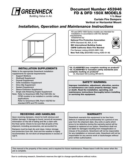
Document Number 453946<br />
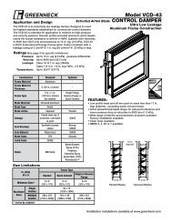
<strong>FD</strong> & D<strong>FD</strong> 150X Models<br />
®<br />
1 1 ⁄2 Hour<br />
<strong>Curtain</strong> <strong>Fire</strong> <strong>Dampers</strong><br />
Vertical or Horizontal Mount<br />
Installation, Operation <strong>and</strong> Maintenance Instructions<br />
<strong>FD</strong> <strong>and</strong> D<strong>FD</strong> 150X Series models are intended for<br />
installation in accordance <strong>with</strong> fire damper<br />
requirements<br />
established by:<br />
National <strong>Fire</strong> Protection Association<br />
NFPA St<strong>and</strong>ard 80, 90A, & 101<br />
IBC International Building Codes<br />
CSFM California State <strong>Fire</strong> Marshal<br />
<strong>Fire</strong> Damper Listing (#3225-0981:102)<br />
New York City (BSA/MEA listing #260-91-M)<br />
L<br />
S TATE<br />
S<br />
I S<br />
T<br />
STATE OF CALIFORNIA<br />
FIR E MAR S HALL<br />
E R V<br />
I N G<br />
E<br />
I C<br />
Installation Supplements<br />
Refer to the appropriate <strong>Greenheck</strong> installation<br />
supplements for special requirements:<br />
• Support Mullions<br />
• Shaftwall Supplement<br />
• Drywall Supplement<br />
• Grille Installation Supplement<br />
• Drive Slip Supplement<br />
• Sealant Supplement<br />
• Sleeve Extension Supplement<br />
• Single side Retaining Angles Supplement<br />
Note: Refer to <strong>Greenheck</strong> IOM, Part #461335, for<br />
CFSD models to be installed in corridor ceiling<br />
applications.<br />
Refer to <strong>Greenheck</strong> IOM, Part # 452763 for<br />
st<strong>and</strong>ard D<strong>FD</strong> <strong>and</strong> <strong>FD</strong> models.<br />
“UL CLASSIFIED (see complete marking on product)”<br />
“UL CLASSIFIED to Canadian safety st<strong>and</strong>ards (see<br />
complete marking on product)”<br />
UL St<strong>and</strong>ard 555 (Listing #R13317)<br />
Safety WARNING:<br />
Improper installation, adjustment, alteration, service<br />
or maintenance can cause property damage, injury<br />
or death. Read the installation, operating, <strong>and</strong><br />
maintenance instructions thoroughly before installing<br />
or servicing this equipment.<br />
Receiving <strong>and</strong> H<strong>and</strong>ling<br />
Upon receiving dampers, check for both obvious <strong>and</strong><br />
hidden damage. If damage is found, record all necessary<br />
information on the bill of lading <strong>and</strong> file a claim <strong>with</strong><br />
the final carrier. Check to be sure that all parts of the<br />
shipment, including accessories, are accounted for.<br />
<strong>Dampers</strong> must be kept dry <strong>and</strong> clean. Indoor storage<br />
<strong>and</strong> protection from dirt, dust <strong>and</strong> the weather is highly<br />
recommended. Do not store at temperatures in excess of<br />
100°F.<br />
Warranty<br />
<strong>Greenheck</strong> warrants this equipment to be free from<br />
defects in material <strong>and</strong> workmanship for a period of one<br />
year from the shipment date. Any units or parts which<br />
prove to be defective during the warranty period will be<br />
repaired or replaced at our option. <strong>Greenheck</strong> shall not<br />
be liable for damages resulting from misapplication or<br />
misuse of its products. <strong>Greenheck</strong> will not be responsible<br />
for any installation or removal costs. <strong>Greenheck</strong> will not be<br />
responsible for any service work or backcharges <strong>with</strong>out<br />
prior written authorization.<br />
This manual is the property of the owner, <strong>and</strong> is required for future maintenance. Please leave it <strong>with</strong> the owner when the<br />
job is complete.<br />
Due to continuing research, <strong>Greenheck</strong> reserves the right to change specifications <strong>with</strong>out notice.
Table of Contents<br />
Pre-Installation Guidelines.......................................................................................................................................... 2<br />
Installation................................................................................................................................................................3-5<br />
Breakaway Connections............................................................................................................................................. 6<br />
Installation for Steel Stud Connection Option........................................................................................................... 7<br />
Damper Maintenance.................................................................................................................................................. 8<br />
Damper Troubleshooting............................................................................................................................................. 8<br />
Pre-Installation Guidelines<br />
The basic intent of a proper installation is to secure the fire damper in, not to, the opening in such a manner as to<br />
prevent distortion <strong>and</strong> disruption of damper operation. This is accomplished by allowing the fire damper in rated<br />
separation openings to exp<strong>and</strong> <strong>and</strong> for the connecting duct to separate in the event of the collapse of the hanging<br />
system. The following items will aid in completing the damper installation in a timely <strong>and</strong> effective manner.<br />
1. Check the schedules for proper damper locations <strong>with</strong>in the building. Visually inspect the damper for damage <strong>and</strong><br />
verify that the fusible link is in place or has not separated. If fusible link is not present or has separated, replace<br />
link. Never install a fire damper <strong>with</strong>out the proper UL approved fusible link in place. (Fusible link is st<strong>and</strong>ard<br />
control option. An electric link may have been provided.)<br />
2. Lift or h<strong>and</strong>le damper using sleeve or frame.<br />
3. Install damper accordingly to comply <strong>with</strong> manufacturer’s appropriate UL procedure file number.<br />
4. Damper must be installed into duct or opening square <strong>and</strong> free of twist or other misalignment. Damper must not be<br />
squeezed or stretched into duct or opening.<br />
5. Damper must be kept clean <strong>and</strong> protected from dirt, dust <strong>and</strong> other foreign materials prior to <strong>and</strong> after installation.<br />
Examples of such foreign materials include, but are not limited to:<br />
a. Mortar dust<br />
b. Drywall dust<br />
c. <strong>Fire</strong>safing materials<br />
d. Wall texture<br />
e. Paint overspray<br />
6. Damper should be sufficiently covered as to prevent overspray of spray-on insulating, wall texturing, or spray<br />
painting when performed <strong>with</strong>in 5 feet of the damper. Excessive dirt or foreign material deposits can cause damper<br />
to bind <strong>and</strong> not operate properly.<br />
7. Caulking is not necessary, nor is it allowed, between the damper sleeve <strong>and</strong> the wall or floor opening (annular<br />
space). However, caulking may be applied to the retaining angles.<br />
8. ACCESS: Suitable access (such that fusible links can be changed) must be provided for damper inspection <strong>and</strong><br />
servicing. Where it is not possible to achieve sufficient size access, it will be necessary to install a removable<br />
section of duct. (Refer to NFPA 90A).<br />
9. The Code Authority Having Jurisdiction (AHJ) must evaluate <strong>and</strong> provide approval of final installation where<br />
variations to these instructions are necessary.<br />
2
Installation - Failure to follow these instructions will void all warranties.<br />
These instructions apply to 11/2 hour rated fire dampers<br />
mounted in masonry, block or stud walls <strong>and</strong> concrete<br />
floors. Specific requirements in these instructions are<br />
m<strong>and</strong>atory. These instructions meet the requirements of<br />
UL 555. Installation shall comply <strong>with</strong> the requirements<br />
of NFPA 90A St<strong>and</strong>ard for the Installation of Air<br />
Conditioning <strong>and</strong> Ventilating Systems. U.L. listing<br />
R13317, California State <strong>Fire</strong> Marshal listings 3225-<br />
981:102, <strong>and</strong> New York City BSA/MEA listing 260-91-M<br />
as they apply to these dampers.<br />
Note: <strong>Fire</strong> dampers are manufactured <strong>and</strong> labelled for<br />
either vertical or horizontal installation. The dampers<br />
must be installed in accordance <strong>with</strong> the labelling.<br />
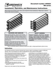
Retaining<br />
Angle<br />
2 in. Max.<br />
Min. 1 in.<br />
Overlap*<br />
Wall or<br />
Floor<br />
Retaining<br />
Angle<br />
Sleeve<br />
Duct<br />
6 in. Max.<br />
Damper<br />
1. NO ADDITIONAL SLEEVES ARE REQUIRED<br />
The fire damper extended frame is an approved<br />
sleeve <strong>and</strong> can be properly installed <strong>with</strong>out the need<br />
for a supplemental field installed sleeve. Damper<br />
frame shall extend a maximum of 6 in. (152mm)<br />
beyond the wall or floor opening on each side.<br />
2. CLEARANCES REQUIRED BETWEEN FIRE<br />
DAMPER SLEEVES AND WALL/FLOOR<br />
OPENINGS<br />
<strong>Fire</strong> damper assemblies exp<strong>and</strong> during periods of<br />
intense heat. Therefore, it is essential that openings<br />
in walls or floors be larger than the fire damper<br />
assembly to allow for this expansion. Minimum<br />
clearances required between the outside of fire<br />
damper sleeve assemblies <strong>and</strong> wall/floor openings<br />
are:<br />
• Galvanized steel fire dampers <strong>and</strong> sleeves: 1/8<br />
in. (3mm) per linear foot of damper width <strong>and</strong><br />
height <strong>with</strong> a minimum clearance of 1/4 in. (6mm)<br />
.Recommended clearances, for width <strong>and</strong>/or height<br />
dimensions of:<br />
1) 48 in. (1219mm) or less: 1/2 in. (13mm) clearance<br />
2) More than 48 in. (1219mm) <strong>and</strong> 96 in. (2438mm)<br />
or less: 1 in. (25mm) clearance<br />
3) More than 96 in. (2438mm): 11/2 in. (38mm)<br />
clearance<br />
These are total clearances (ignoring fastener heads)<br />
<strong>and</strong> do not need to be equally spaced around<br />
the damper. Refer to Section 3 <strong>and</strong> Figure 1 for<br />
additional installation considerations.<br />
Example:<br />
A 12 in. x 12 in. (305mm x 305mm) damper would<br />
require a minimum clearance of 1/4 in. (6mm).<br />
A 48 in. x 12 in. (1219mm x 305mm) damper<br />
would require a minimum clearance of 1/2 in.<br />
(13mm) on width <strong>and</strong> 1/4 in. (6mm) on height.<br />
6 in. Max.<br />
2 in. Max.<br />
*only applicable for damper sizes above 36 in. x 36 in.<br />
Figure 1: Retaining angle installation.<br />
3. SECURING THE FIRE DAMPER TO WALL AND<br />
FLOOR OPENINGS<br />
<strong>Fire</strong> damper assemblies must be installed in wall <strong>and</strong><br />
floor openings using retaining angles on each side of<br />
the wall or floor as described below:<br />
• Retaining angles for 11/2 hour rated dampers <strong>with</strong><br />
a width <strong>and</strong> height 48 in. (1219mm) or less must be<br />
a minimum of 20 ga. (1mm). Retaining angles for<br />
all 3 hour rated dampers <strong>and</strong> all dampers <strong>with</strong> a<br />
width or height greater than 48 in. (1219mm) must<br />
be a minimum of 16 gauge (1.5mm). The leg of the<br />
retaining angle on the damper sleeve shall be a<br />
minimum of 11/4 in. (32mm). The leg of the retaining<br />
angle on the wall/floor shall be long enough to cover<br />
the annular space <strong>and</strong> overlap the wall/floor by a<br />
minimum of 1 in. (25mm).<br />
• Retaining angles must be attached to the damper<br />
using one or more of the following methods of<br />
attachment:<br />
• tack or spot welds<br />
• #10 sheetmetal screws<br />
• 1/4 in. (6mm) bolts <strong>and</strong> nuts<br />
• 3/16 in. (4.7mm) steel pop rivets<br />
Attachments must be spaced a maximum of 6 in.<br />
(152mm) on center <strong>and</strong> a maximum of 2 in. (51mm)<br />
from corners. The angles must be attached to all 4<br />
sides of the sleeve <strong>with</strong> butt joints at each corner.<br />
A minimum of two attachments are required on<br />
each side, top <strong>and</strong> bottom. The angles need not be<br />
attached to each other at the corners.<br />
• Retaining angles should not be fastened to the wall/<br />
floor material. The angles should only s<strong>and</strong>wich the<br />
wall/floor <strong>and</strong> allow for damper expansion during<br />
periods of intense heat.<br />
3
4. CONNECTING DUCTS TO THE FIRE DAMPER<br />
All duct connections to <strong>FD</strong> & D<strong>FD</strong> 150X series extended frame dampers must be “breakaway” type connections. All<br />
connections shown 1/4 on in. minimum page 5 & 6 are considered breakaway. Factory furnished duct collars on types R & CR fire<br />
total clearance<br />
dampers are also considered breakaway(see Figure 2 & 3).<br />
1/4 in. minimum<br />
total clearance<br />
1/4 in. minimum<br />
total clearance<br />
Retaining Angles<br />
(See Section 4)<br />
Wall or Floor<br />
See Section 2<br />
Maximum<br />
6 in.<br />
Maximum<br />
6 in.<br />
Maximum<br />
6 in.<br />
Maximum Wall or Floor<br />
6 in.<br />
Wall or Floor<br />
Maximum<br />
6 in.<br />
Maximum<br />
6 in.<br />
“K” side<br />
Wall or Floor<br />
Sleeve<br />
(see sections 2 & 3)<br />
See Section 2<br />
Damper<br />
Duct<br />
Duct<br />
Duct<br />
Retaining Angles<br />
Retaining Angles<br />
(See Retaining Section Angles 3)<br />
(See Section 3)<br />
(See Section 3)<br />
Damper<br />
Damper Damper<br />
Type A<br />
Type A<br />
Wall Wall or Floor or Floor<br />
Wall or Floor<br />
Type A<br />
Retaining Angles<br />
(See Section 4)<br />
See Section 2<br />
Damper<br />
Damper<br />
Damper<br />
“K” side<br />
Wall or<br />
Floor<br />
See Section 2<br />
Damper<br />
Sleeve<br />
(see sections 2 & 3)<br />
Duct<br />
Duct<br />
Duct<br />
Duct<br />
Type B<br />
Wall or Floor<br />
On types R & CR factory<br />
furnished duct collar<br />
qualifies as breakaway<br />
connection.<br />
On types R & CR factory<br />
On types furnished R & duct CR factory collar<br />
furnished qualifies duct as breakaway collar<br />
qualifies connection. as breakaway<br />
connection.<br />
Type B<br />
Type B<br />
Wall or Floor<br />
Wall or Floor<br />
Type B<br />
Duct<br />
Duct<br />
Damper<br />
“K” side<br />
Wall or<br />
floor<br />
Type C, CO, CR, & R<br />
Sleeve<br />
Duct<br />
Damper<br />
Duct<br />
Type C, CO, CR, & R<br />
Damper<br />
On types R & CR factory<br />
furnished duct collar qualifies<br />
as breakaway connection, see<br />
Section 5<br />
Type C, CO, CR, & R<br />
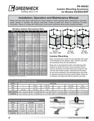
Figure 2: Vertical Mount Type A, Type B, <strong>and</strong> Type C,<br />
CO, CR, R damper installation diagrams.<br />
Type C, CO, CR, & R<br />
Figure 3: Horizontal Mount Type A, Type B, <strong>and</strong> Type C,<br />
CO, CR, R damper installation diagrams.<br />
When dampers installed horizontally, the ramp must be<br />
positioned up as shown in above drawings.<br />
4<br />
Table 1<br />
Damper Model<br />
Maximum Sizes for Single<br />
Section <strong>Dampers</strong>*<br />
in. (mm)<br />
<strong>FD</strong>-150X (H or V) 48 x 48 (1219 x 1219)<br />
D<strong>FD</strong>-150X (V) 36 x 36 (914 x 914)<br />
D<strong>FD</strong>-150X (H) 30 x 30 (762 x 762)<br />
Note: V = Vertical mount & H = Horizontal<br />
* Sizes are based on damper <strong>with</strong> no transitions.
Recommended Preparation of Openings in Wood <strong>and</strong> Metal Stud Walls<br />
• Frame wall openings as shown in Figure 4 <strong>and</strong> 4A.<br />
• Gypsum wall board must be fastened 12 in. on center to all stud <strong>and</strong> runner flanges surrounding opening (see<br />
Figure 4 <strong>and</strong> 4A).<br />
• Prepare opening between studs <strong>and</strong> sleeve assembly as shown below (see Figure 5).<br />
• All construction <strong>and</strong> fasteners must meet then requirements of the appropriate wall design.<br />
(See UL <strong>Fire</strong> Resistance Directory)<br />
24 in. o.c.<br />
Maximum<br />
(metal studs)<br />
24 in. o.c.<br />
Maximum<br />
(metal studs)<br />
Ceiling Runner<br />
12 in.<br />
24 in. o.c.<br />
Maximum<br />
2 Panhead<br />
Screws<br />
2 in. (51mm)<br />
2 in. (51mm)<br />
16 in. o.c.<br />
Maximum<br />
(wood studs)<br />
16 in. o.c.<br />
Maximum<br />
(wood studs)<br />
Floor Runner<br />
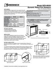
Figure 4: Preparation detail for opening in stud wall.<br />
Second set of studs are not required on openings<br />
36 in. x 36 in. (914mm x 914mm) or smaller.<br />
Metal Stud Construction<br />
Gypsum Wallboard<br />
Stud or Runner<br />
Retaining<br />
Angle<br />
1 in. Min.<br />
Damper<br />
Sleeve<br />
In metal stud construction,<br />
exposed steel surfaces need<br />
not be covered <strong>with</strong> gypsum<br />
wallboard.<br />
Figure 4A<br />
Metal Stud Construction<br />
Metal stud only<br />
Wooden Stud Construction<br />
Gypsum Wallboard<br />
Gypsum Wa llboard<br />
Stud or Runner<br />
Stud or Runner<br />
Retaining<br />
Angle<br />
Retaining<br />
Angl e<br />
1 in. Min.<br />
1 in. Min.<br />
Damper<br />
Sleeve<br />
In metal stud construction,<br />
exposed steel surfaces need<br />
not be covered <strong>with</strong> gypsum<br />
wallboard.<br />
Wooden Stud Construction<br />
Damper<br />
Sleeve<br />
In wood stud construction,<br />
gypsum wallboard must cover<br />
all wood stud surfaces.<br />
Figure 5: Detail of retaining angles <strong>and</strong> gypsum board application for metal <strong>and</strong> wooden stud construction.<br />
5
Duct-Sleeve Connections<br />
Traditional Breakaway Style Transverse Joints<br />
Transverse joints illustrated in Figure 6 have always<br />
been approved as breakaway connections. SMACNA<br />
testing has also approved the following variations as<br />
breakaway connections.<br />
• The breakaway connections shown to the right can<br />
be applied <strong>with</strong> maximum of (2) #10 sheet metal<br />
screws on each side <strong>and</strong> on the bottom located in<br />
the center of the slip pocket <strong>and</strong> penetrating both<br />
sides of the slip pocket.<br />
• Transverse joints illustrated can<br />
be applied as top <strong>and</strong> bottom<br />
joints <strong>with</strong> Drive Slip - side<br />
Drive Slip Joint<br />
joints in duct heights up to 20<br />
in. (508mm).<br />
Round <strong>and</strong> Oval Duct Breakaway Connections<br />
Round or flat oval ducts connected to factory supplied<br />
Type R, CR, or CO damper collars may use #10 sheet<br />
metal screws as follows:<br />
• Ducts 22 in. (559mm) wide (or dia.) <strong>and</strong> smaller may<br />
use 3 screws.<br />
• Ducts larger than 22 in. (559mm) wide (or dia.) may<br />
use 5 screws.<br />
Plain “S” Slip Hemmed “S” Slip Double “S” Slip<br />
Inside Slip Joint St<strong>and</strong>ing “S” St<strong>and</strong>ing “S” (Alt.)<br />
St<strong>and</strong>ing “S” (Alt.) St<strong>and</strong>ing “S” St<strong>and</strong>ing “S”<br />
(Bar Reinforced) (Angle Reinforced)<br />
Figure 6: Traditional breakaway style transverse joints.<br />
NOTE: All breakaway connections described may have<br />
duct sealant, PA2084T duct sealant adhesive manufactured<br />
by Precision, DP1010 water base duct sealant by Design<br />
Polymetrics, Grey Pookie, Ductmate PROseal ® , or<br />
CL Ward S Seal applied in accordance <strong>with</strong> SMACNA<br />
recommendations.<br />
Proprietary Flange System Breakaway Connections<br />
(Ductmate, Ward, Nexus)<br />
Flanged connection systems manufactured by<br />
Ductmate, Ward, <strong>and</strong> Nexus are approved as breakaway<br />
connections when installed as illustrated in Figure 7.<br />
6 in. long 1/16 in. max.<br />
thickness plastic cleats;<br />
12 in. c-c (min. 1 per side)<br />
Flanged system angles<br />
<strong>Fire</strong> Damper Sleeve<br />
(TDC by Lockformer, TDF by Engle)<br />
TDC <strong>and</strong> TDF systems are approved as breakaway<br />
connections when installed as described in the SMACNA<br />
Duct Construction St<strong>and</strong>ards. St<strong>and</strong>ard 6 in. metal clips<br />
may be used <strong>with</strong> spacing (see Figure 8). Three-eighth<br />
in. metal bolts <strong>and</strong> nuts may be used to fasten together<br />
corner pieces (see Figure 9).<br />
(Attach per<br />
manufacturer’s<br />
instructions)<br />
Duct<br />
Figure 7:<br />
Neoprene gasket<br />
between all angles<br />
Detail of manufactured flanged system<br />
breakaway connections.<br />
Do not bolt corners<br />
60 in. Duct<br />
4 Req’d.<br />
Clip Spacing<br />
6 in.<br />
7 in.<br />
Std. Clip<br />
Length<br />
9 in.<br />
6 in. 6 in.<br />
7 in.<br />
Duct End<br />
Flange<br />
Corner Piece<br />
Sleeve<br />
Typical TDC/TDF joint<br />
Duct<br />
48 in. Duct<br />
3 Req’d.<br />
36 in. Duct<br />
3 Req’d.<br />
24 in. Duct<br />
2 Req’d.<br />
18 in. Duct &<br />
Smaller<br />
1 Req’d.<br />
5 in. 5 in.<br />
5 in.<br />
CL<br />
Duct<br />
5 in.<br />
3/8 in. bolt<br />
(optional)<br />
Figure 8:<br />
6<br />
Detail of proprietary flanged system breakaway<br />
connections.<br />
Figure 9: Detail of bolted corner.
Installation for Steel Stud Connection (SSC) Option<br />
These instructions apply to 11/2 hour rated fire dampers mounted in steel stud walls. Specific requirements in these<br />
instructions are m<strong>and</strong>atory. These instructions meet the requirements of UL555. Installation shall comply <strong>with</strong> the<br />
requirements of NFPA 90A St<strong>and</strong>ard for the Installation of Air Conditioning <strong>and</strong> Ventilating Systems. U.L. listings<br />
R13317 <strong>and</strong> R13743, California State <strong>Fire</strong> Marshal listings 3225-981:102 <strong>and</strong> 3225-1241:101, <strong>and</strong> New York City BSA/<br />
MEA listing 260-91-M as they apply to these dampers.<br />
1. NO ADDITIONAL SLEEVES OR ANGLES ARE<br />
REQUIRED<br />
The fire damper extended frame is an approved<br />
sleeve <strong>and</strong> the Steel Stud Connection (SSC) Option<br />
allows fastening of the fire damper sleeve directly<br />
to the wall's steel stud framing. Damper frame shall<br />
extend a maximum of 6 in. (152mm) beyond the wall<br />
opening on either side. Maximum size fire damper<br />
that may be installed using this SSC option is 36 in. W<br />
x 36 in. H (914mm x 914mm).<br />
2. INSTALLATION<br />
<strong>Fire</strong> damper <strong>with</strong> SSC option must be in place before<br />
the wall is constructed or it can be installed as the<br />
wall is being constructed. Wall opening is framed<br />
around the fire damper before sheet rock or other<br />
wall board material is applied to the steel studs. This<br />
installation provides appropriate protection for duct<br />
penetrations in fire resistant wall construction using<br />
steel studs <strong>with</strong> a fire resistance rating less than 3<br />
hours. The following wall design 3 numbers (as detailed<br />
in the UL <strong>Fire</strong> Resistance Directory) are appropriate<br />
for fire damper installations using this SSC option:<br />
1 Hour Design: U405, U406, U422, U434, U448, U451,<br />
U456, U457, U465, U468, U469, U485, U494<br />
11/2 Hour Design: U449, U452, U470, U471<br />
2<br />
2<br />
2 Hour Design: U403, U411, U412, U421, U425, U428,<br />
U429, U443, U453, U474, U475, U477, U484, U491,<br />
U495<br />
3. FRAMING OF WALL OPENING<br />
Form a wall opening 1/8 in. (3mm) to 1/4 in. (6mm)<br />
larger than the OD of the fire damper's extended<br />
frame (sleeve) using the same metal studs <strong>and</strong><br />
techniques required by the wall design per the UL<br />
<strong>Fire</strong> Resistance Directory. Open side of the steel stud<br />
channels shall face the fire damper <strong>and</strong> encompass<br />
the damper's retaining bar.<br />
4. APPLY WALLBOARD AFTER DAMPER<br />
INSTALLATION<br />
After damper is installed, wallboard shall be applied<br />
to steel stud framework in the manner required by<br />
the wall design per the UL <strong>Fire</strong> Resistance Directory<br />
listing. Around the damper perimeter use a minimum<br />
of 2 connections per side, spaced 12 in. (305mm)<br />
maximum <strong>and</strong> located a maximum of 2 in. (51mm)<br />
from each corner. No additional retaining angles are<br />
required to complete the installation.<br />
5. CONNECTING DUCTS TO THE FIRE DAMPER<br />
3<br />
All duct connections to <strong>FD</strong> & D<strong>FD</strong> 150X series<br />
extended frame dampers must be “breakaway” type<br />
connections. All connections shown on page 5 & 6<br />
are considered breakaway. Factory furnished duct<br />
collars on types R, CR, & CO fire dampers are also<br />
considered breakaway.<br />
Item<br />
3 Description<br />
3<br />
1 <strong>FD</strong>150X fire damper <strong>with</strong> SSC option<br />
2 Steel stud wall (see UL <strong>Fire</strong> Resistance Directory for specific<br />
details)<br />
3 Steel stud frame around opening in wall<br />
4 Duct connection (see section 6)<br />
5 Wallboard (see UL <strong>Fire</strong> Resistance Directory for specific<br />
details)<br />
6 Fasteners (see UL <strong>Fire</strong> Resistance Directory <strong>and</strong> Section 5)<br />
2<br />
3<br />
3<br />
3<br />
6<br />
3<br />
6<br />
3<br />
5<br />
3<br />
5<br />
1<br />
1<br />
Retaining<br />
Bar<br />
1<br />
Retaining<br />
Bar<br />
1<br />
4<br />
4<br />
Top Cross-section View<br />
4 2<br />
Top Cross-section ViewSide Cross-Section View<br />
of Damper in Wall<br />
3<br />
5<br />
4 2<br />
Side Cross-Section View<br />
of Damper in Wall<br />
3<br />
6<br />
7<br />
1<br />
Retaining<br />
1<br />
4
Damper Maintenance<br />
<strong>Dampers</strong> shall be maintained, cycled, <strong>and</strong> tested in intervals as stated in the latest editions of NFPA 90A, 92A, <strong>and</strong> UL<br />
864 unless local codes require more frequent inspections.<br />
<strong>Dampers</strong> do not typically require maintenance as long as they are kept dry <strong>and</strong> clean. If cleaning is necessary, use<br />
mild detergents or solvents. If lubrication is desired, do not use oil-based lubricants or any other lubricants that attract<br />
contaminant’s such as dust.<br />
Damper Trouble Shooting<br />
The following is a cause <strong>and</strong> correction list for common concerns <strong>with</strong> the dampers.<br />
Symptom Possible Cause Corrective Action<br />
Damper does not fully open <strong>and</strong>/or<br />
fully close<br />
Frame is 'racked' causing blades to<br />
bind on jamb<br />
Screws in damper linkage<br />
Contaminant's on damper<br />
Link separated Heat Replace link<br />
Adjust frame such that it is square<br />
<strong>and</strong> plumb<br />
Locate screws <strong>and</strong> remove<br />
Clean <strong>with</strong> a non-oil based solvent<br />
(see Damper Maintenance)<br />
Our Commitment<br />
As a result of our commitment to continuous improvement, <strong>Greenheck</strong> reserves the right to change specifications<br />
<strong>with</strong>out notice.<br />
Specific <strong>Greenheck</strong> product warranties are located on greenheck.com <strong>with</strong>in the product area tabs <strong>and</strong> in<br />
the Library under Warranties.<br />
®<br />
Phone: (715) 359-6171 • Fax: (715) 355-2399 • E-mail: gfcinfo@greenheck.com • Website: www.greenheck.com<br />
453946• D<strong>FD</strong> & <strong>FD</strong> 150X Series Rev. 15, August 2013 Copyright 2013 © <strong>Greenheck</strong> Fan Corporation<br />
8