XN12L2xx 32-bit MCU Family ARM Cortex-M0 Core, Up to 88K ...
XN12L2xx 32-bit MCU Family ARM Cortex-M0 Core, Up to 88K ...
XN12L2xx 32-bit MCU Family ARM Cortex-M0 Core, Up to 88K ...

You also want an ePaper? Increase the reach of your titles
YUMPU automatically turns print PDFs into web optimized ePapers that Google loves.
<strong>XN12L2xx</strong><br />
<strong>32</strong>-<strong>bit</strong> <strong>MCU</strong> <strong>Family</strong><br />
<strong>ARM</strong> <strong>Cortex</strong>-<strong>M0</strong> <strong>Core</strong>, <strong>Up</strong> <strong>to</strong> <strong>88K</strong> Flash and 12K RAM<br />
USER MANUAL<br />
1 Introduction ........................................................................................................................................................ 18<br />
1.1 General ...................................................................................................................................................... 18<br />
1.2 Features .................................................................................................................................................... 18<br />
1.3 Part Function Summary ............................................................................................................................. 19<br />
2 Package and Pin Assignment ............................................................................................................................ 20<br />
2.1 General Description ................................................................................................................................... 20<br />
2.2 QFP 48 Package ....................................................................................................................................... 20<br />
2.3 QFP 64 Package ....................................................................................................................................... 21<br />
2.4 Pin Description .......................................................................................................................................... 22<br />
2.5 Peripheral Pin Group ................................................................................................................................. 27<br />
3 System Block Diagram ....................................................................................................................................... 30<br />
4 System Description ............................................................................................................................................ 31<br />
4.1 <strong>ARM</strong> <strong>Cortex</strong>-<strong>M0</strong> <strong>Core</strong> ............................................................................................................................ 31<br />
4.2 Memory Map .............................................................................................................................................. <strong>32</strong><br />
4.3 <strong>Cortex</strong>-<strong>M0</strong> <strong>Core</strong> System Control Block .................................................................................................. 37<br />
4.3.1 General Description ................................................................................................................. 37<br />
4.3.2 CPUID Register........................................................................................................................ 37<br />
4.3.3 Interrupt Control and State Register ........................................................................................ 37<br />
4.3.4 Application Interrupt and Reset Control Register .................................................................... 39<br />
4.3.5 System Control Register .......................................................................................................... 39<br />
4.3.6 Configuration and Control Register.......................................................................................... 40<br />
4.3.7 System Handle Priority Registers ............................................................................................ 40<br />
© 2010 Xinnova Technology Ltd. All rights reserved. The Xinnova logo is registered trademarks of Xinnova Technology Ltd. This Datasheet may be<br />
revised by subsequent versions or modifications without prior notice.
<strong>XN12L2xx</strong><br />
4.4 Nested Vec<strong>to</strong>red Interrupt Controller (NVIC) ............................................................................................ 41<br />
4.4.1 NVIC Description...................................................................................................................... 41<br />
4.4.2 Nested Vec<strong>to</strong>red Interrupt Controller Register List .................................................................. 43<br />
4.4.3 Interrupt Set-enable Register ................................................................................................... 44<br />
4.4.4 Interrupt Clear-enable Register ................................................................................................ 44<br />
4.4.5 Interrupt Set-pending Register ................................................................................................. 44<br />
4.4.6 Interrupt Clear-pending Register.............................................................................................. 45<br />
4.4.7 Interrupt Priority Registers ....................................................................................................... 45<br />
4.4.7.1 NMI Interrupt Source Configuration Register .................................................................. 46<br />
4.5 System Tick Timer ..................................................................................................................................... 47<br />
4.5.1 System Timer Control and Status Register ............................................................................. 47<br />
4.5.2 System Timer Reload Value Register ...................................................................................... 48<br />
4.5.3 System Timer Current Value Register ..................................................................................... 48<br />
4.5.4 Usage of System Tick Timer .................................................................................................... 48<br />
4.6 System Control .......................................................................................................................................... 49<br />
4.6.1 System Reset ........................................................................................................................... 51<br />
4.6.1.1 System Memory Remap Register ................................................................................... 52<br />
4.6.1.2 System Reset Status Register ........................................................................................ 52<br />
4.6.1.3 PIO State at System Reset ............................................................................................. 53<br />
4.6.1.4 Software Reset ................................................................................................................ 53<br />
4.6.1.5 POR ................................................................................................................................. 53<br />
4.6.1.6 BOD ................................................................................................................................. 53<br />
4.6.2 Clock control ............................................................................................................................ 54<br />
4.6.2.1 General description ......................................................................................................... 54<br />
2 www.xinnovatech.com
<strong>XN12L2xx</strong><br />
4.6.2.2 System Oscilla<strong>to</strong>r Control ................................................................................................ 54<br />
4.6.2.3 Watchdog Oscilla<strong>to</strong>r Control ........................................................................................... 55<br />
4.6.2.4 Internal Resonant Crystal Control ................................................................................... 56<br />
4.6.2.5 System PLL ..................................................................................................................... 56<br />
4.6.2.6 Main Clock ....................................................................................................................... 59<br />
4.6.2.7 System AHB Clock Control ............................................................................................. 60<br />
4.6.2.8 UART Clock Control ........................................................................................................ 62<br />
4.6.2.9 CLKOUT Clock Control ................................................................................................... 63<br />
4.6.2.10 IOCONFIG Filter Clock Control ....................................................................................... 64<br />
4.6.3 Power Management ................................................................................................................. 64<br />
4.6.3.1 Power Control Register ................................................................................................... 65<br />
4.6.3.2 General Data Registers 0 <strong>to</strong> 3 ......................................................................................... 66<br />
4.6.3.3 WAKEUP and RTC Configuration Register .................................................................... 66<br />
4.6.3.4 Deep-sleep Configuration Register ................................................................................. 66<br />
4.6.3.5 Wake-up Configuration Register ..................................................................................... 67<br />
4.6.3.6 Power-down Configuration Register ............................................................................... 68<br />
4.6.3.7 Active Mode ..................................................................................................................... 69<br />
4.6.3.8 Sleep Mode ..................................................................................................................... 70<br />
4.6.3.9 Deep-sleep Mode ............................................................................................................ 70<br />
4.6.3.10 Power-down Mode .......................................................................................................... 72<br />
4.6.4 Deep-sleep Wake <strong>Up</strong> Control .................................................................................................. 74<br />
4.6.4.1 Deep-sleep Wake <strong>Up</strong> Control Register ........................................................................... 74<br />
4.6.4.2 Deep-sleep Wake <strong>Up</strong> Signal Enable Register ................................................................ 75<br />
4.6.4.3 Deep-sleep Wake <strong>Up</strong> Signal Reset Register .................................................................. 76<br />
www.xinnovatech.com 3
<strong>XN12L2xx</strong><br />
4.6.4.4 Deep-sleep Wake <strong>Up</strong> Signal Status Register ................................................................. 78<br />
4.6.5 Miscellaneous .......................................................................................................................... 79<br />
4.6.5.1 Peripheral Reset Control Register .................................................................................. 79<br />
4.7 I/O configuration ........................................................................................................................................ 80<br />
4.7.1 General Description of IOCON Register .................................................................................. 80<br />
4.7.1.1 Pin Function .................................................................................................................... 82<br />
4.7.1.2 Pin Mode ......................................................................................................................... 82<br />
4.7.1.3 Pin Drive .......................................................................................................................... 82<br />
4.7.1.4 Open-drain Mode ............................................................................................................ 82<br />
4.7.1.5 A/D-mode ........................................................................................................................ 82<br />
4.7.1.6 TWS Mode (I2C Compatible) .......................................................................................... 82<br />
4.7.1.7 Programmable Glitch Filter.............................................................................................. 82<br />
4.7.2 IOCON Register List ................................................................................................................ 83<br />
4.7.2.1 PIO0_0 IOCON Register ................................................................................................. 85<br />
4.7.2.2 PIO0_1 IOCON Register ................................................................................................. 85<br />
4.7.2.3 PIO0_2 IOCON Register ................................................................................................. 86<br />
4.7.2.4 PIO0_3 IOCON Register ................................................................................................. 87<br />
4.7.2.5 PIO0_4 IOCON Register ................................................................................................. 88<br />
4.7.2.6 PIO0_5 IOCON Register ................................................................................................. 89<br />
4.7.2.7 PIO0_6 IOCON Register ................................................................................................. 90<br />
4.7.2.8 PIO0_7 IOCON Register ................................................................................................. 91<br />
4.7.2.9 PIO0_8 IOCON Register ................................................................................................. 92<br />
4.7.2.10 PIO0_9 IOCON Register ................................................................................................. 93<br />
4.7.2.11 PIO0_10 IOCON Register ............................................................................................... 94<br />
4 www.xinnovatech.com
<strong>XN12L2xx</strong><br />
4.7.2.12 PIO0_11 IOCON Register ............................................................................................... 95<br />
4.7.2.13 PIO0_12 IOCON Register ............................................................................................... 96<br />
4.7.2.14 PIO0_13 IOCON Register ............................................................................................... 98<br />
4.7.2.15 PIO0_14 IOCON Register ............................................................................................... 99<br />
4.7.2.16 PIO0_15 IOCON Register ............................................................................................. 100<br />
4.7.2.17 PIO0_16 IOCON Register ............................................................................................. 101<br />
4.7.2.18 PIO0_17 IOCON Register ............................................................................................. 102<br />
4.7.2.19 PIO0_18 IOCON Register ............................................................................................. 103<br />
4.7.2.20 PIO0_19 IOCON Register ............................................................................................. 104<br />
4.7.2.21 PIO0_20 IOCON Register ............................................................................................. 105<br />
4.7.2.22 PIO0_21 IOCON Register ............................................................................................. 106<br />
4.7.2.23 PIO0_22 IOCON Register ............................................................................................. 107<br />
4.7.2.24 PIO0_23 IOCON Register ............................................................................................. 108<br />
4.7.2.25 PIO0_24 IOCON Register ............................................................................................. 109<br />
4.7.2.26 PIO0_25 IOCON Register ............................................................................................. 110<br />
4.7.2.27 PIO0_26 IOCON Register ............................................................................................. 111<br />
4.7.2.28 PIO0_27 IOCON Register ............................................................................................. 112<br />
4.7.2.29 PIO0_28 IOCON Register ............................................................................................. 113<br />
4.7.2.30 PIO0_29 IOCON Register ............................................................................................. 114<br />
4.7.2.31 PIO0_30 IOCON Register ............................................................................................. 115<br />
4.7.2.<strong>32</strong> PIO0_31 IOCON Register ............................................................................................. 116<br />
4.7.2.33 PIO1_0 IOCON Register ............................................................................................... 117<br />
4.7.2.34 PIO1_1 IOCON Register ............................................................................................... 118<br />
4.7.2.35 PIO1_2 IOCON Register ............................................................................................... 119<br />
www.xinnovatech.com 5
<strong>XN12L2xx</strong><br />
4.7.2.36 PIO1_3 IOCON Register ............................................................................................... 120<br />
4.7.2.37 PIO1_4 IOCON Register ............................................................................................... 121<br />
4.7.2.38 PIO1_5 IOCON Register ............................................................................................... 122<br />
4.7.2.39 PIO1_6 IOCON Register ............................................................................................... 123<br />
4.7.2.40 PIO2_0 IOCON Register ............................................................................................... 124<br />
4.7.2.41 PIO2_1 IOCON Register ............................................................................................... 125<br />
4.7.2.42 PIO2_2 IOCON Register ............................................................................................... 126<br />
4.7.2.43 PIO2_3 IOCON Register ............................................................................................... 127<br />
4.7.2.44 PIO2_4 IOCON Register ............................................................................................... 128<br />
4.7.2.45 PIO2_5 IOCON Register ............................................................................................... 129<br />
4.7.2.46 PIO2_6 IOCON Register ............................................................................................... 130<br />
4.7.2.47 PIO2_7 IOCON Register ............................................................................................... 131<br />
4.7.2.48 PIO2_8 IOCON Register ............................................................................................... 1<strong>32</strong><br />
4.7.2.49 PIO2_9 IOCON Register .............................................................................................. 133<br />
4.7.2.50 PIO2_10 IOCON Register ............................................................................................ 134<br />
4.7.2.51 PIO2_11 IOCON Register ............................................................................................ 135<br />
4.7.2.52 PIO2_12 IOCON Register ............................................................................................. 136<br />
4.7.2.53 PIO2_13 IOCON Register ............................................................................................. 137<br />
4.7.2.54 PIO2_14 IOCON Register ............................................................................................. 138<br />
4.7.2.55 PIO2_15 IOCON Register ............................................................................................. 139<br />
5 GPIO ................................................................................................................................................................ 141<br />
5.1 General Description ................................................................................................................................. 141<br />
5.2 Pin Description ........................................................................................................................................ 141<br />
5.3 Control Register Description ................................................................................................................... 141<br />
6 www.xinnovatech.com
<strong>XN12L2xx</strong><br />
5.3.1 GPIO Mask Register .............................................................................................................. 142<br />
5.3.2 GPIO Pin Value Register ....................................................................................................... 142<br />
5.3.3 GPIO Pin Output Register ...................................................................................................... 143<br />
5.3.4 GPIO Pin Output Set Register ............................................................................................... 143<br />
5.3.5 GPIO Pin Output Clear Register ............................................................................................ 143<br />
5.3.6 GPIO NOT Register ............................................................................................................... 144<br />
5.3.7 GPIO Data Direction Register ................................................................................................ 144<br />
5.3.8 GPIO Interrupt Sense Register .............................................................................................. 144<br />
5.3.9 GPIO Interrupt Both Edges Sense Register .......................................................................... 144<br />
5.3.10 GPIO Interrupt Event Register ............................................................................................... 145<br />
5.3.11 GPIO Interrupt Mask Register ................................................................................................ 145<br />
5.3.12 GPIO Raw Interrupt Status Register ...................................................................................... 145<br />
5.3.13 GPIO Masked Interrupt Status Register ................................................................................ 145<br />
5.3.14 GPIO Interrupt Clear Register ................................................................................................ 146<br />
6 16-Bit Timer/Counter ........................................................................................................................................ 147<br />
6.1 General Description ................................................................................................................................. 147<br />
6.2 Pin Description ........................................................................................................................................ 149<br />
6.3 Register Description ................................................................................................................................ 149<br />
6.3.1 Interrupt Register ................................................................................................................... 150<br />
6.3.2 Timer Control Register ........................................................................................................... 151<br />
6.3.3 Timer Counter Register .......................................................................................................... 151<br />
6.3.4 Prescale Register ................................................................................................................... 151<br />
6.3.5 Prescale Counter Register ..................................................................................................... 151<br />
6.3.6 Match Control Register .......................................................................................................... 152<br />
www.xinnovatech.com 7
<strong>XN12L2xx</strong><br />
6.3.7 Match Registers ..................................................................................................................... 153<br />
6.3.8 Capture Control Register ....................................................................................................... 153<br />
6.3.9 Capture Registers .................................................................................................................. 155<br />
6.3.10 External Match Register ......................................................................................................... 155<br />
6.3.11 Count Control Register .......................................................................................................... 157<br />
6.3.11.1 Edge Count Mode ......................................................................................................... 159<br />
6.3.11.2 Quadrature Count Mode................................................................................................ 159<br />
6.3.11.3 Triggered Count Mode .................................................................................................. 159<br />
6.3.11.4 Signed Count Mode ....................................................................................................... 159<br />
6.3.11.5 Gated Count Mode ........................................................................................................ 160<br />
6.3.12 Timer PWM Control register .................................................................................................. 160<br />
6.3.12.1 Rules for Single Edge Controlled PWM Outputs .......................................................... 160<br />
7 <strong>32</strong>-Bit Timer/Counter ........................................................................................................................................ 162<br />
7.1 General Description ................................................................................................................................. 162<br />
7.2 Pin Description ........................................................................................................................................ 163<br />
7.3 Register Description ................................................................................................................................ 164<br />
7.3.1 Interrupt Register ................................................................................................................... 165<br />
7.3.2 Timer Control Register ........................................................................................................... 165<br />
7.3.3 Timer Counter Register .......................................................................................................... 166<br />
7.3.4 Prescale Register ................................................................................................................... 166<br />
7.3.5 Prescale Counter Register ..................................................................................................... 166<br />
7.3.6 Match Control Register .......................................................................................................... 166<br />
7.3.7 Match Registers ..................................................................................................................... 168<br />
7.3.8 Capture Control Register ....................................................................................................... 168<br />
8 www.xinnovatech.com
<strong>XN12L2xx</strong><br />
7.3.9 Capture Register .................................................................................................................... 169<br />
7.3.10 External Match Register ......................................................................................................... 169<br />
7.3.11 Count Control Register .......................................................................................................... 171<br />
7.3.12 PWM Control Register ........................................................................................................... 173<br />
7.3.13 Rules for Single Edge Controlled PWM Outputs ................................................................... 174<br />
8 Watchdog Timer (WDT) ................................................................................................................................... 176<br />
8.1 General Description ................................................................................................................................. 176<br />
8.2 Register Description ................................................................................................................................ 177<br />
8.3 Watchdog Mode Register ........................................................................................................................ 177<br />
8.3.1 Watchdog Timer Constant Register ....................................................................................... 179<br />
8.3.2 Watchdog Feed Register ....................................................................................................... 179<br />
8.3.3 Watchdog Timer Value Register ............................................................................................ 180<br />
8.3.4 Watchdog Timer Clock Source Selection Register ................................................................ 180<br />
8.3.5 Watchdog Timer Warning Interrupt Register ......................................................................... 181<br />
8.3.6 Watchdog Timer Window Register ........................................................................................ 181<br />
8.4 Watchdog Timer Clock and Power Control ............................................................................................. 181<br />
8.5 Watchdog Lock Feature .......................................................................................................................... 182<br />
8.6 Watchdog Timing Examples .................................................................................................................... 182<br />
9 CRC Module ..................................................................................................................................................... 184<br />
9.1 General Description ................................................................................................................................. 184<br />
9.2 CRC Module Interface Register Description ........................................................................................... 184<br />
15.1.1 CRC Mode Register ............................................................................................................... 184<br />
15.1.2 CRC Seed Register ............................................................................................................... 185<br />
15.1.3 CRC Checksum Register ....................................................................................................... 185<br />
www.xinnovatech.com 9
<strong>XN12L2xx</strong><br />
15.1.4 CRC Data Register ................................................................................................................ 185<br />
9.3 Functions Description .............................................................................................................................. 185<br />
15.1.5 CRC Calculation..................................................................................................................... 185<br />
10 UART................................................................................................................................................................ 188<br />
10.1 General Description ........................................................................................................................ 188<br />
10.2 Pin Description ................................................................................................................................ 189<br />
10.3 UART Register Description............................................................................................................. 189<br />
10.3.1 UART Receiver Buffer Register ............................................................................................. 189<br />
10.3.2 UART Transmitter Holding Register ...................................................................................... 190<br />
10.3.3 UART State Register ............................................................................................................. 190<br />
10.3.4 UART Control Register .......................................................................................................... 190<br />
10.3.5 UART Interrupt Status Register ............................................................................................. 191<br />
10.3.6 UART Baudrate Divider Register ........................................................................................... 192<br />
10.4 Operation Description ..................................................................................................................... 192<br />
10.4.1 UART Communication Convention ........................................................................................ 192<br />
10.4.2 IrDA Function ......................................................................................................................... 193<br />
11 SPI .................................................................................................................................................................... 194<br />
11.1 General Description ........................................................................................................................ 194<br />
11.2 Pin Description ................................................................................................................................ 194<br />
11.3 Register Description ....................................................................................................................... 195<br />
11.3.1 SPI Control Register 0 ........................................................................................................... 195<br />
11.3.2 SPI Control Register 1 ........................................................................................................... 196<br />
11.3.3 SPI Data Register .................................................................................................................. 197<br />
11.3.4 SPI Status Register ................................................................................................................ 197<br />
10 www.xinnovatech.com
<strong>XN12L2xx</strong><br />
11.3.5 SPI Clock Prescale Register .................................................................................................. 198<br />
11.3.6 SPI Interrupt Mask Set/Clear Register ................................................................................... 198<br />
11.3.7 SPI Raw Interrupt Status Register ......................................................................................... 198<br />
11.3.8 SPI Masked Interrupt Status Register ................................................................................... 199<br />
11.3.9 SPI Interrupt Clear Register ................................................................................................... 199<br />
11.3.10 SPI DMA Control Register ..................................................................................................... 199<br />
11.4 Operation ........................................................................................................................................ 200<br />
11.4.1 SPI Frame Format.................................................................................................................. 200<br />
11.4.2 SSI Frame Format.................................................................................................................. 204<br />
12 TWS ................................................................................................................................................................. 206<br />
12.1 General Description ........................................................................................................................ 206<br />
12.2 Pin Description ................................................................................................................................ 206<br />
12.3 Register Description ....................................................................................................................... 207<br />
12.3.1 TWS Control Set register ....................................................................................................... 208<br />
12.3.2 TWS Status Register ............................................................................................................. 209<br />
12.3.3 TWS Data Register ................................................................................................................ 210<br />
12.3.4 TWS Slave Address Register 0 ............................................................................................. 210<br />
12.3.5 TWS HIGH Duty Cycle register .............................................................................................. 210<br />
12.3.6 TWS Low Duty Cycle register ................................................................................................ 210<br />
12.3.7 TWS Control Clear Register .................................................................................................. 211<br />
12.3.8 TWS Slave Address Registers ............................................................................................... 211<br />
12.3.9 TWS Data Buffer Register ..................................................................................................... 212<br />
12.3.10 TWS Mask Registers ............................................................................................................. 212<br />
12.4 TWS Operation ............................................................................................................................... 212<br />
www.xinnovatech.com 11
<strong>XN12L2xx</strong><br />
12.4.1 Master Transmitter Mode ....................................................................................................... 212<br />
12.4.2 Master Receiver Mode ........................................................................................................... 214<br />
12.4.3 Slave Receiver Mode ............................................................................................................. 216<br />
12.4.4 Slave Transmitter Mode ......................................................................................................... 218<br />
12.4.5 Detailed State Tables ............................................................................................................. 219<br />
12.4.6 TWS State Service Routines ................................................................................................. 222<br />
12.4.6.1 Initialization Routine ...................................................................................................... 222<br />
12.4.6.2 Start Master Transmit Function ..................................................................................... 222<br />
12.4.6.3 Start Master Receive Function ...................................................................................... 223<br />
12.4.6.4 TWS Interrupt Routine ................................................................................................... 223<br />
12.4.6.5 Non Mode Specific States ............................................................................................. 223<br />
12.4.6.6 Master Transmitter States ............................................................................................. 224<br />
12.4.6.7 Master Receive States .................................................................................................. 225<br />
12.4.6.8 Slave Receiver States ................................................................................................... 226<br />
12.4.6.9 Slave Transmitter States ............................................................................................... 227<br />
13 RTC .................................................................................................................................................................. 228<br />
13.1 General Description ........................................................................................................................ 228<br />
13.2 Pin Description ................................................................................................................................ 228<br />
13.3 RTC Register Description ............................................................................................................... 228<br />
13.3.1 RTC Data Register ................................................................................................................. 228<br />
13.3.2 RTC Match Register .............................................................................................................. 228<br />
13.3.3 RTC Load Register ................................................................................................................ 229<br />
13.3.4 RTC Control Register ............................................................................................................. 229<br />
13.3.5 RTC Interrupt Control Set/Clear Register .............................................................................. 229<br />
12 www.xinnovatech.com
<strong>XN12L2xx</strong><br />
13.3.6 RTC Interrupt Status Register ................................................................................................ 229<br />
13.3.7 RTC Masked Interrupt Status Register .................................................................................. 230<br />
13.3.8 RTC Interrupt Clear Register ................................................................................................. 230<br />
13.4 Functional Description .................................................................................................................... 230<br />
14 ADC/DAC and On-chip Temperature Sensor .................................................................................................. 231<br />
14.1 General Description ........................................................................................................................ 231<br />
14.2 Pin description ................................................................................................................................ 231<br />
14.3 Register Description ....................................................................................................................... 231<br />
14.3.1 ADC Control Register ............................................................................................................ 2<strong>32</strong><br />
14.3.2 ADC Global Data Register ..................................................................................................... 233<br />
14.3.3 ADC Interrupt Enable Register .............................................................................................. 234<br />
14.3.4 ADC Data Registers ............................................................................................................... 234<br />
14.3.5 ADC Interrupt Status Register ............................................................................................... 235<br />
14.3.6 High Limit Control Register .................................................................................................... 235<br />
14.3.7 Low Limit Control Register ..................................................................................................... 236<br />
14.3.8 Software Sample Control Register......................................................................................... 236<br />
14.3.9 D/A Control Register .............................................................................................................. 237<br />
14.3.10 D/A Data Register .................................................................................................................. 237<br />
14.4 Operation ........................................................................................................................................ 238<br />
14.4.1 Select ADC Converter for Each AD Input Channel ................................................................ 238<br />
14.4.2 ADC Hardware-Triggered Conversion ................................................................................... 238<br />
14.4.3 Interrupts ................................................................................................................................ 238<br />
14.4.4 ADC DMA Control .................................................................................................................. 238<br />
14.4.5 DAC DMA Control .................................................................................................................. 238<br />
www.xinnovatech.com 13
<strong>XN12L2xx</strong><br />
14.4.6 On-chip Temperature Sensor ................................................................................................ 239<br />
15 Compara<strong>to</strong>r ...................................................................................................................................................... 241<br />
15.1 General Description ........................................................................................................................ 241<br />
15.2 Pin Description ................................................................................................................................ 242<br />
15.3 Register Description ....................................................................................................................... 242<br />
15.3.1 Compara<strong>to</strong>r Control Register ................................................................................................. 242<br />
15.3.2 Voltage Ladder Register ........................................................................................................ 244<br />
15.3.3 Interrupt Status Register ........................................................................................................ 244<br />
15.4 Functional Description .................................................................................................................... 245<br />
15.4.1 Input Multiplexer ..................................................................................................................... 245<br />
15.4.2 Interrupts ................................................................................................................................ 246<br />
15.4.3 Compara<strong>to</strong>r Outputs .............................................................................................................. 246<br />
16 DMA ................................................................................................................................................................. 247<br />
16.1 General Description ........................................................................................................................ 247<br />
16.2 Operations ...................................................................................................................................... 247<br />
16.3 Memory Regions Accessible By the Micro DMA Controller ........................................................... 248<br />
16.3.1 DMA System Connections ..................................................................................................... 248<br />
16.4 Clocking and Power Control ........................................................................................................... 249<br />
16.4.1 DMA Status Register ............................................................................................................. 250<br />
16.4.2 DMA Configuration Register .................................................................................................. 250<br />
16.4.3 Channel Control Base Pointer Register ................................................................................. 251<br />
16.4.4 Channel Wait on Request Status Register ............................................................................ 251<br />
16.4.5 Channel Software Request Register...................................................................................... 251<br />
16.4.6 Channel Useburst Set Register ............................................................................................. 251<br />
14 www.xinnovatech.com
<strong>XN12L2xx</strong><br />
16.4.7 Channel Useburst Clear Register .......................................................................................... 252<br />
16.4.8 Channel Request Mask Set Register ..................................................................................... 252<br />
16.4.9 Channel Request Mask Clear Register ................................................................................. 253<br />
16.5 Channel Enable Set Register ......................................................................................................... 253<br />
16.5.1 Channel Enable Clear Register ............................................................................................. 254<br />
16.5.2 Channel Priority Set Register ................................................................................................. 254<br />
16.5.3 Channel Priority Clear Register ............................................................................................. 255<br />
16.5.4 Channel DMA Interrupt Status Register ................................................................................ 255<br />
16.5.5 Channel DMA Interrupt Enable Register ............................................................................... 255<br />
16.6 Functional Description .................................................................................................................... 256<br />
16.6.1 DMA Control Signals .............................................................................................................. 256<br />
16.6.2 DMA Ar<strong>bit</strong>ration ...................................................................................................................... 256<br />
16.6.3 DMA Priority ........................................................................................................................... 256<br />
16.6.4 DMA Cycle Types .................................................................................................................. 257<br />
16.6.5 DMA Control ........................................................................................................................... 258<br />
16.6.5.1 Control Data Configuration ............................................................................................ 259<br />
17 Flash/SRAM memory and ISP/IAP Functions.................................................................................................. 262<br />
17.1 Flash/Boot ROM Organization and Access Speed ........................................................................ 262<br />
17.2 Flash Configuration/Control Register ............................................................................................. 263<br />
17.2.1 Flash Access Cycle Register ................................................................................................. 263<br />
17.2.2 Device ID Register ................................................................................................................. 263<br />
17.2.3 Device Hardware Version Register ........................................................................................ 264<br />
17.2.4 Device Unique Serial No Register ......................................................................................... 264<br />
17.3 Flash Memory Security ................................................................................................................... 264<br />
www.xinnovatech.com 15
<strong>XN12L2xx</strong><br />
17.3.1 Memory A/B Configure ........................................................................................................... 265<br />
17.3.2 Enable Password Protection .................................................................................................. 265<br />
17.3.3 Protection Summary .............................................................................................................. 265<br />
17.4 ISP Pro<strong>to</strong>col and Command ........................................................................................................... 266<br />
17.4.1 ISP Command List ................................................................................................................. 266<br />
17.4.2 Command Return Code ......................................................................................................... 267<br />
17.4.2.1 Erase Sec<strong>to</strong>r(s) ............................................................................................................. 268<br />
17.4.3 Sec<strong>to</strong>r Blank Check ............................................................................................................... 268<br />
17.4.3.1 Write Data <strong>to</strong> RAM Memory .......................................................................................... 268<br />
17.4.3.2 Copy RAM Data <strong>to</strong> Flash............................................................................................... 269<br />
17.4.3.3 Compare Memory Data ................................................................................................. 269<br />
17.4.3.4 Read Data from Memory ............................................................................................... 269<br />
17.4.3.5 Chip Erase ..................................................................................................................... 270<br />
17.4.3.6 Retrieve Device ID ........................................................................................................ 270<br />
17.4.3.7 Retrieve BSL Version .................................................................................................... 270<br />
17.4.3.8 Run Specific Address Code .......................................................................................... 270<br />
17.4.3.9 Password Verification .................................................................................................... 271<br />
17.4.3.10 Set New Password ........................................................................................................ 271<br />
17.4.3.11 Set B Boundary ............................................................................................................. 271<br />
17.4.3.12 Password Status ........................................................................................................... 272<br />
17.5 IAP Command and Entry Address .................................................................................................. 272<br />
18 IRC_NOT_POWERED 0x07SWD ................................................................................................................... 274<br />
18 SWD ................................................................................................................................................................. 275<br />
18.1 General Description ........................................................................................................................ 275<br />
16 www.xinnovatech.com
<strong>XN12L2xx</strong><br />
18.2 Pin Description ................................................................................................................................ 275<br />
18.3 Debug Operation ............................................................................................................................ 275<br />
19 Revision His<strong>to</strong>ry ............................................................................................................................................... 276<br />
www.xinnovatech.com 17
<strong>XN12L2xx</strong><br />
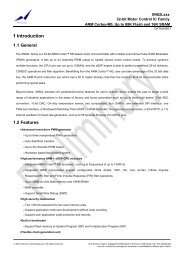
1 Introduction<br />
1.1 General<br />
The <strong>XN12L2xx</strong> is Xinnova’s <strong>32</strong>-<strong>bit</strong> <strong>ARM</strong> <strong>Cortex</strong>-<strong>M0</strong> core series <strong>MCU</strong>. It focuses on high performance requirement<br />
application in industrial and home au<strong>to</strong>mation.<br />
<strong>XN12L2xx</strong> integrates the rich peripheral and features for user’s options:<br />
<strong>Up</strong> <strong>to</strong> 2 12-<strong>bit</strong> ADC converters support up 8 channels AD input; one 10-<strong>bit</strong> DAC output channel; two compara<strong>to</strong>rs; on-chip<br />
temperature sensor; four UARTs; one SPI interface; one Two-Wire Serial(TWS) interface which is compatible I 2 C; hardware<br />
CRC and DMA module; a windowed Watchdog Timer (WDT); four general purpose timers/counters; a <strong>32</strong>-<strong>bit</strong> RTC; a 1 %<br />
internal oscilla<strong>to</strong>r; and up <strong>to</strong> 55 General Purpose I/O (GPIO) pins.<br />
1.2 Features<br />
• High performance <strong>ARM</strong><br />
– Integrated <strong>ARM</strong> <strong>Cortex</strong>-<strong>M0</strong> processor, running at frequencies of up <strong>to</strong> 100 MHz<br />
– <strong>Up</strong> <strong>to</strong> <strong>88K</strong>B on-chip flash memory and up <strong>to</strong> 12KB SRAM<br />
– DMA controller<br />
– CRC module<br />
– Support Serial Wire Debug (SWD)<br />
• High security mechanism<br />
– Two 128 <strong>bit</strong>s password for two user memory areas<br />
– Support application multi-user development without code unveiling<br />
– Support user application code protection and security<br />
• Built in bootloader<br />
– Support flash memory In-System-Program (ISP) and In-Application-Program (IAP)<br />
– Support user application code protection and security<br />
• Flexible clock generation unit<br />
– Crystal oscilla<strong>to</strong>r with an operating range of 0.5 MHz <strong>to</strong> 16 MHz<br />
– 20 MHz Internal Resonant Crystal (IRC) oscilla<strong>to</strong>r trimmed <strong>to</strong> 1% accuracy<br />
– Integrated Phase Locked Loop (PLL) allows CPU operation up <strong>to</strong> the maximum CPU rate<br />
– Support <strong>32</strong>K Real-Time Clock (RTC) timer<br />
• Enhanced Timer/Counter<br />
– Two 16-<strong>bit</strong> and two <strong>32</strong>-<strong>bit</strong> timers/counters<br />
– Each timer/counter support four match/capture functions<br />
– Support Edge count, Gated count, Quadrature count, Trigger count and Signed count mode<br />
18 www.xinnovatech.com
<strong>XN12L2xx</strong><br />
• Analog peripherals<br />
– UP <strong>to</strong> two 12-<strong>bit</strong> ADC support up <strong>to</strong> 8 channel with 1MHz sample rate<br />
– One channel 10-<strong>bit</strong> DAC, 1MHz converting speed<br />
– Two highly flexible analog compara<strong>to</strong>rs<br />
– On-chip temperature sensor support -40°C <strong>to</strong> +120°C detection<br />
• Rich communication interface and GPIO<br />
– Four UARTs with baudrate detection and IrDA supporting<br />
– SPI controller with FIFO and multi-pro<strong>to</strong>col capabilities<br />
– Two Wire Serial (TWS) interface<br />
– <strong>Up</strong> <strong>to</strong> 55 General Purpose I/O (GPIO) pins<br />
• Power management<br />
– Three reduced power modes: Sleep, Deep-sleep, and Power-down<br />
– Processor wake-up from Deep-sleep mode via using 12 port pins<br />
– Processor wake-up from Deep-power down and Deep-sleep modes via the RTC<br />
– Brownout detection(BOD) with two separate thresholds for interrupt and forced reset.<br />
– Power-On Reset (POR)<br />
– Integrated Power Management Unit (PMU)<br />
• Operating Temperature<br />
– Industrial (-40°C <strong>to</strong> +85°C)<br />
• Unique device serial number for identification<br />
• 3.3 V power supply<br />
• 64-pin and 48-pin LQFP package<br />
1.3 Part Function Summary<br />
Part<br />
Flash<br />
(KB)<br />
SRAM<br />
(KB)<br />
T/C DMA PLL CRC RTC ADC DAC Comp<br />
°C<br />
Sensor<br />
UART TWS SPI WDT GPIO Package<br />
XN12L202 <strong>32</strong> 4 4 √ √ √ √<br />
8ch/12<strong>bit</strong>/<br />
1ADC<br />
- 2 - 4 1 1 √ 39/ 55 LQFP48/ 64<br />
XN12L206 48 8 4 √ √ √ √<br />
8ch/12<strong>bit</strong>/<br />
1ADC<br />
- 2 - 4 1 1 √ 39/ 55 LQFP48/ 64<br />
XN12L208 64 8 4 √ √ √ √<br />
8ch/12<strong>bit</strong>/<br />
2ADC<br />
- 2 √ 4 1 1 √ 39/ 55 LQFP48/ 64<br />
XN12L210 88 12 4 √ √ √ √<br />
8ch/12<strong>bit</strong>/<br />
2ADC<br />
- 2 √ 4 1 1 √ 39/ 55 LQFP48/ 64<br />
XN12L212 88 12 4 √ √ √ √<br />
8ch/12<strong>bit</strong>/2A<br />
DC<br />
1ch/<br />
10<strong>bit</strong><br />
2 √ 4 1 1 √ 55 LQFP64<br />
www.xinnovatech.com 19
<strong>XN12L2xx</strong><br />
2 Package and Pin Assignment<br />
2.1 General Description<br />
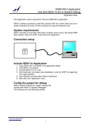
<strong>XN12L2xx</strong> comes in LQFP 64 and LQFP 48 package. To save package pin, all pins have more than one function except<br />
power supply pin. And the pin function is configurable by IOCON register. The default function will be set after system reset.<br />
2.2 QFP 48 Package<br />
VSSIO<br />
VDD(IO)<br />
RTCXIN<br />
RTCXOUT<br />
VDD(3V3)<br />
VSS<br />
PIO1_6/CT16B1_CAP1/CT16B1_MAT1<br />
PIO1_5/AD7/CT16B1_CAP0/CT16B1_MAT0<br />
PIO1_4/AD6<br />
PIO1_3/AD5/WAKEUP<br />
PIO1_2/SWDIO/AD4<br />
R/PIO1_1/AD3<br />
48 47 46 45 44 43 42 41 40 39 38 37<br />
XTALIN<br />
1<br />
36<br />
R/PIO1_0/AD2<br />
XTALOUT<br />
2<br />
35<br />
R/PIO0_31/AD1<br />
VREF_ADC<br />
3<br />
34<br />
R/PIO0_30/AD0<br />
PIO0_19/ACMP0_I0/CT<strong>32</strong>B0_CAP1/CT<strong>32</strong>B0_MAT1<br />
4<br />
33<br />
PIO0_18/SWCLK/CT<strong>32</strong>B0_CAP0/CT<strong>32</strong>B0_MAT0<br />
PIO0_20/ACMP0_I1/CT<strong>32</strong>B0_CAP2/CT<strong>32</strong>B0_MAT2<br />
5<br />
<strong>32</strong><br />
PIO0_17/MOSI/RXD3<br />
PIO0_21/ACMP0_I2/CT<strong>32</strong>B0_CAP3/CT<strong>32</strong>B0_MAT3<br />
PIO0_22/ACMP0_I3<br />
6<br />
7<br />
QFP48<br />
31<br />
30<br />
PIO0_16/MISO/CT16B1_CAP1/CT16B1_MAT1/TXD3<br />
PIO0_15/SSEL/CT16B1_CAP0/CT16B1_MAT0/RXD2<br />
PIO0_23/ACMP1_I0/CT<strong>32</strong>B1_CAP0/CT<strong>32</strong>B1_MAT0<br />
8<br />
29<br />
PIO0_14/SCK/TXD2<br />
PIO0_24/ACMP1_I1/CT<strong>32</strong>B1_CAP1/CT<strong>32</strong>B1_MAT1<br />
9<br />
28<br />
RESET/PIO0_13<br />
SWDIO/ACMP1_I2/CT<strong>32</strong>B1_CAP2/CT<strong>32</strong>B1_MAT2/PIO0_25<br />
10<br />
27<br />
PIO0_12/CLKOUT/CT16B0_CAP1/CT16B0_MAT1<br />
SWCLK/ACMP1_I3/CT<strong>32</strong>B1_CAP3/CT<strong>32</strong>B1_MAT3/PIO0_26<br />
11<br />
26<br />
PIO0_11/SDA/CT16B0_CAP0/CT16B0_MAT0<br />
PIO0_27/ACMP0_O/DA0<br />
12<br />
13 14 15 16 17 18 19 20 21 22 23 24<br />
25<br />
PIO0_10/SCL<br />
PIO0_28/ACMP1_O/DA0/CT16B0_CAP0/CT16B0_MAT0<br />
PIO0_29/CT16B0_CAP1/CT16B0_MAT1<br />
PIO0_0<br />
PIO0_1/RXD0/CT<strong>32</strong>B0_CAP0/CT<strong>32</strong>B0_MAT0<br />
PIO0_2/TXD0/CT<strong>32</strong>B0_CAP1/CT<strong>32</strong>B0_MAT1<br />
PIO0_3/CT<strong>32</strong>B0_CAP2/CT<strong>32</strong>B0_MAT2<br />
PIO0_4/CT<strong>32</strong>B0_CAP3/CT<strong>32</strong>B0_MAT3<br />
PIO0_5<br />
PIO0_6/CT<strong>32</strong>B1_CAP0/CT<strong>32</strong>B1_MAT0<br />
PIO0_7/CT<strong>32</strong>B1_CAP1/CT<strong>32</strong>B1_MAT1<br />
PIO0_8/RXD1/CT<strong>32</strong>B1_CAP2/CT<strong>32</strong>B1_MAT2<br />
PIO0_9/TXD1/CT<strong>32</strong>B1_CAP3/CT<strong>32</strong>B1_MAT3<br />
20 www.xinnovatech.com
<strong>XN12L2xx</strong><br />
www.xinnovatech.com 21<br />
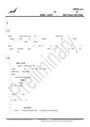
2.3 QFP 64 Package<br />
QFP64<br />
PIO0_23/ACMP1_I0/CT<strong>32</strong>B1_CAP0/CT<strong>32</strong>B1_MAT0<br />
16<br />
15<br />
14<br />
13<br />
12<br />
11<br />
10<br />
9<br />
8<br />
7<br />
5<br />
6<br />
4<br />
3<br />
1<br />
2<br />
PIO0_17/MOSI/RXD3<br />
PIO0_16/MISO/CT16B1_CAP1/CT16B1_MAT1/TXD3<br />
PIO0_15/SSEL/CT16B1_CAP0/CT16B1_MAT0/RXD2<br />
VDD(IO)<br />
PIO2_11/CT<strong>32</strong>B1_CAP3/CT<strong>32</strong>B1_MAT3/RXD1<br />
PIO2_10/CT<strong>32</strong>B1_CAP2/CT<strong>32</strong>B1_MAT2/TXD1<br />
PIO2_9/CT<strong>32</strong>B1_CAP1/CT<strong>32</strong>B1_MAT1<br />
PIO2_8/CT<strong>32</strong>B1_CAP0/CT<strong>32</strong>B1_MAT0<br />
VDD(3V3)<br />
PIO1_5/AD7/CT16B1_CAP0/CT16B1_MAT0<br />
VSS<br />
RTCXIN<br />
PIO1_6/CT16B1_CAP1/CT16B1_MAT1<br />
PIO1_4/AD6<br />
VSSIO<br />
PIO1_3/AD5/WAKEUP<br />
PIO1_2/SWDIO/AD4<br />
R/PIO1_1/AD3<br />
RTCXINOUT<br />
49<br />
50<br />
51<br />
52<br />
53<br />
54<br />
55<br />
56<br />
57<br />
58<br />
60 59<br />
61<br />
62<br />
64 63<br />
R/PIO0_31/AD1<br />
R/PIO0_30/AD0<br />
PIO0_18/SWCLK/CT<strong>32</strong>B0_CAP0/CT<strong>32</strong>B0_MAT0<br />
PIO0_14/SCK/TXD2<br />
RESET/PIO0_13<br />
PIO0_12/CLKOUT/CT16B0_CAP1/CT16B0_MAT1<br />
PIO0_11/SDA/CT16B0_CAP0/CT16B0_MAT0<br />
PIO0_10/SCL<br />
R/PIO1_0/AD2<br />
PIO2_7/CT<strong>32</strong>B0_CAP3/CT<strong>32</strong>B0_MAT3/RXD2<br />
PIO2_6/CT<strong>32</strong>B0_CAP2/CT<strong>32</strong>B0_MAT2/TXD2<br />
PIO2_5/CT<strong>32</strong>B0_CAP1/CT<strong>32</strong>B0_MAT1<br />
PIO2_4/CT<strong>32</strong>B0_CAP0/CT<strong>32</strong>B0_MAT0<br />
33<br />
34<br />
35<br />
36<br />
37<br />
38<br />
39<br />
40<br />
41<br />
42<br />
44<br />
43<br />
45<br />
46<br />
48<br />
47<br />
PIO0_29/CT16B0_CAP1/CT16B0_MAT1<br />
PIO0_0<br />
PIO0_1/RXD0/CT<strong>32</strong>B0_CAP0/CT<strong>32</strong>B0_MAT0<br />
PIO0_2/TXD0/CT<strong>32</strong>B0_CAP1/CT<strong>32</strong>B0_MAT1<br />
PIO0_3/CT<strong>32</strong>B0_CAP2/CT<strong>32</strong>B0_MAT2<br />
PIO0_4/CT<strong>32</strong>B0_CAP3/CT<strong>32</strong>B0_MAT3<br />
PIO0_5<br />
PIO0_6/CT<strong>32</strong>B1_CAP0/CT<strong>32</strong>B1_MAT0<br />
PIO0_7/CT<strong>32</strong>B1_CAP1/CT<strong>32</strong>B1_MAT1<br />
PIO0_8/RXD1/CT<strong>32</strong>B1_CAP2/CT<strong>32</strong>B1_MAT2<br />
PIO0_9/TXD1/CT<strong>32</strong>B1_CAP3/CT<strong>32</strong>B1_MAT3<br />
PIO0_28/ACMP1_O/CT16B0_CAP0/CT16B0_MAT0<br />
PIO2_0/CT16B0_CAP0/CT16B0_MAT0<br />
PIO2_1/CT16B0_CAP1/CT16B0_MAT1/RXD0<br />
PIO2_2/CT16B1_CAP0/CT16B1_MAT0/TXD0<br />
PIO2_3/CT16B1_CAP1/CT16B1_MAT1<br />
<strong>32</strong><br />
31<br />
30<br />
29<br />
28<br />
27<br />
26<br />
25<br />
24<br />
23<br />
21 22<br />
20<br />
19<br />
17 18<br />
XTALOUT<br />
VREF_ADC<br />
PIO0_19/ACMP0_I0/CT<strong>32</strong>B0_CAP1/CT<strong>32</strong>B0_MAT1<br />
PIO0_20/ACMP0_I1/CT<strong>32</strong>B0_CAP2/CT<strong>32</strong>B0_MAT2<br />
PIO0_21/ACMP0_I2/CT<strong>32</strong>B0_CAP3/CT<strong>32</strong>B0_MAT3<br />
PIO0_22/ACMP0_I3<br />
PIO0_24/ACMP1_I1/CT<strong>32</strong>B1_CAP1/CT<strong>32</strong>B1_MAT1<br />
SWDIO/ACMP1_I2/CT<strong>32</strong>B1_CAP2/CT<strong>32</strong>B1_MAT2/PIO0_25<br />
SWCLK/ACMP1_I3/CT<strong>32</strong>B1_CAP3/CT<strong>32</strong>B1_MAT3/PIO0_26<br />
PIO0_27/ACMP0_O/DA0<br />
XTALIN<br />
PIO2_12/RXD1<br />
PIO2_13/TXD1<br />
PIO2_14/TXD3<br />
PIO2_15/RXD3
<strong>XN12L2xx</strong><br />
2.4 Pin Description<br />
Table 2-1: Pin assignment and description<br />
Symbol Pin Wake <strong>Up</strong><br />
Type Default Description<br />
48 64<br />
input<br />
PIO0_0 15 19 yes I/O I; PU PIO0_0 — General purpose digital input/output pin<br />
PIO0_1/<br />
RXD0/<br />
CT<strong>32</strong>B0_CAP0/<br />
CT<strong>32</strong>B0_MAT0<br />
PIO0_2/<br />
TXD0/<br />
CT<strong>32</strong>B0_CAP1/<br />
CT<strong>32</strong>B0_MAT1<br />
PIO0_3/<br />
CT<strong>32</strong>B0_CAP2/<br />
CT<strong>32</strong>B0_MAT2<br />
PIO0_4/<br />
CT<strong>32</strong>B0_CAP3/<br />
CT<strong>32</strong>B0_MAT3<br />
16 20 yes I/O I; PU PIO0_1 — General purpose digital input/output pin<br />
- I - RXD0 — Receiver input for UART0<br />
- I - CT<strong>32</strong>B0_CAP0 — Capture input, channel 0 for <strong>32</strong>-<strong>bit</strong> timer 0<br />
- O - CT<strong>32</strong>B0_MAT0 — Match output, channel 0 for <strong>32</strong>-<strong>bit</strong> timer 0<br />
17 21 yes I/O I; PU PIO0_2 — General purpose digital input/output pin<br />
- O - TXD0 — Transmitter output for UART0<br />
- I - CT<strong>32</strong>B0_CAP1 — Capture input, channel 1 for <strong>32</strong>-<strong>bit</strong> timer 0<br />
- O - CT<strong>32</strong>B0_MAT1 — Match output, channel 1 for <strong>32</strong>-<strong>bit</strong> timer 0<br />
18 22 yes I/O I; PU PIO0_3 — General purpose digital input/output pin.<br />
- I - CT<strong>32</strong>B0_CAP2 — Capture input, channel 2 for <strong>32</strong>-<strong>bit</strong> timer 0<br />
- O - CT<strong>32</strong>B0_MAT2 — Match output, channel 2 for <strong>32</strong>-<strong>bit</strong> timer 0<br />
19 23 yes I/O I; PU PIO0_4 — General purpose digital input/output pin<br />
- I - CT<strong>32</strong>B0_CAP3 — Capture input, channel 3 for <strong>32</strong>-<strong>bit</strong> timer 0<br />
- O - CT<strong>32</strong>B0_MAT3 — Match output, channel 3 for <strong>32</strong>-<strong>bit</strong> timer 0<br />
PIO0_5 20 24 yes I/O I; PU PIO0_5 — General purpose digital input/output pin<br />
PIO0_6/<br />
CT<strong>32</strong>B1_CAP0/<br />
CT<strong>32</strong>B1_MAT0<br />
PIO0_7/<br />
CT<strong>32</strong>B1_CAP1/<br />
CT<strong>32</strong>B1_MAT1<br />
PIO0_8/<br />
RXD1/<br />
CT<strong>32</strong>B1_CAP2/<br />
CT<strong>32</strong>B1_MAT2<br />
PIO0_9/<br />
TXD1/<br />
CT<strong>32</strong>B1_CAP3/<br />
CT<strong>32</strong>B1_MAT3<br />
PIO0_10/<br />
SCL<br />
PIO0_11/<br />
SDA/<br />
CT16B0_CAP0/<br />
21 25 yes I/O I; PU PIO0_6 — General purpose digital input/output pin<br />
- I - CT<strong>32</strong>B1_CAP0 — Capture input, channel 0 for <strong>32</strong>-<strong>bit</strong> timer 1<br />
- O - CT<strong>32</strong>B1_MAT0 — Match output, channel 0 for <strong>32</strong>-<strong>bit</strong> timer 1<br />
22 26 yes I/O I; PU PIO0_7 — General purpose digital input/output pin<br />
- I - CT<strong>32</strong>B1_CAP1 — Capture input, channel 1 for <strong>32</strong>-<strong>bit</strong> timer 1<br />
- O - CT<strong>32</strong>B1_MAT1 — Match output, channel 1 for <strong>32</strong>-<strong>bit</strong> timer 1<br />
23 27 yes I/O I; PU PIO0_8 — General purpose digital input/output pin<br />
- I - RXD1 — Receiver input for UART1<br />
- I - CT<strong>32</strong>B1_CAP2 — Capture input, channel 2 for <strong>32</strong>-<strong>bit</strong> timer 1<br />
- O - CT<strong>32</strong>B1_MAT2 — Match output, channel 2 for <strong>32</strong>-<strong>bit</strong> timer 1<br />
24 28 yes I/O I; PU PIO0_9 — General purpose digital input/output pin<br />
- O - TXD1 — Transmitter output for UART1<br />
- I - CT<strong>32</strong>B1_CAP3 — Capture input, channel 3 for <strong>32</strong>-<strong>bit</strong> timer 1<br />
- O - CT<strong>32</strong>B1_MAT3 — Match output, channel 3 for <strong>32</strong>-<strong>bit</strong> timer 1<br />
25 37 yes I/O I; IA PIO0_10 — General purpose digital input/output pin<br />
- I/O - SCL — TWS-bus clock input/output<br />
26 38 yes I/O I; IA PIO0_11 — General purpose digital input/output pin<br />
- I/O - SDA — TWS-bus data input/output<br />
- I - CT16B0_CAP0 — Capture input, channel 0 for 16-<strong>bit</strong> timer 0<br />
22 www.xinnovatech.com
<strong>XN12L2xx</strong><br />
Symbol Pin Wake <strong>Up</strong><br />
Type Default Description<br />
48 64<br />
input<br />
CT16B0_MAT0 - O - CT16B0_MAT0 — Match output, channel 0 for 16-<strong>bit</strong> timer 0<br />
PIO0_12/<br />
27 39 - I/O I; PU PIO0_12 — General purpose digital input/output pin. High-current<br />
output driver<br />
CLKOUT/<br />
CT16B0_CAP1/<br />
CT16B0_MAT1<br />
RESET/<br />
PIO0_13<br />
PIO0_14/<br />
SCK/<br />
TXD2<br />
PIO0_15/<br />
SSEL/<br />
CT16B1_CAP0/<br />
CT16B1_MAT0/<br />
RXD2<br />
PIO0_16/<br />
MISO/<br />
CT16B1_CAP1/<br />
CT16B1_MAT1/<br />
TXD3<br />
PIO0_17/<br />
MOSI/<br />
RXD3<br />
PIO0_18/<br />
SWCLK/<br />
CT<strong>32</strong>B0_CAP0/<br />
CT<strong>32</strong>B0_MAT0<br />
PIO0_19/<br />
ACMP0_I0/<br />
CT<strong>32</strong>B0_CAP1/<br />
CT<strong>32</strong>B0_MAT1<br />
PIO0_20/<br />
ACMP0_I1/<br />
CT<strong>32</strong>B0_CAP2/<br />
CT<strong>32</strong>B0_MAT2<br />
PIO0_21/<br />
ACMP0_I2/<br />
- O - CLKOUT — Clock out pin<br />
- I - CT16B0_CAP1 — Capture input, channel 1 for 16-<strong>bit</strong> timer 0<br />
- O - CT16B0_MAT1 — Match output, channel 1 for 16-<strong>bit</strong> timer 0<br />
28 40 - I I; PU RESET — External reset input<br />
- I/O - PIO0_13 — General purpose digital input/output pin<br />
29 41 - I/O I; PU PIO0_14 — General purpose digital input/output pin<br />
- I/O - SCK — Serial clock for SPI<br />
- I - TXD2 — Transmitter output for UART2<br />
30 42 - I/O I; PU PIO0_15 — General purpose digital input/output pin<br />
- I/O - SSEL — Slave select for SPI<br />
- I - CT16B1_CAP0 — Capture input, channel 0 for 16-<strong>bit</strong> timer 1<br />
- O - CT16B1_MAT0 — Match output, channel 0 for 16-<strong>bit</strong> timer 1<br />
- O - RXD2 — Receiver input for UART2<br />
31 43 - I/O I; PU PIO0_16 — General purpose digital input/output pin<br />
- I/O - MISO — Master In Slave Out for SPI<br />
- I - CT16B1_CAP1 — Capture input, channel 1 for 16-<strong>bit</strong> timer 1<br />
- O - CT16B1_MAT1 — Match output, channel 1 for 16-<strong>bit</strong> timer 1<br />
- I - TXD3 — Transmitter output for UART3<br />
<strong>32</strong> 44 - I/O I; PU PIO0_17 — General purpose digital input/output pin<br />
- I/O - MOSI — Master Out Slave In for SPI<br />
- O - RXD3 — Receiver input for UART3<br />
33 45 - I/O I; PU PIO0_18 — General purpose digital input/output pin<br />
- I - SWCLK — Serial wire clock, alternate location<br />
- I - CT<strong>32</strong>B0_CAP0 — Capture input, channel 0 for <strong>32</strong>-<strong>bit</strong> timer 0<br />
- O - CT<strong>32</strong>B0_MAT0 — Match output, channel 0 for <strong>32</strong>-<strong>bit</strong> timer 0<br />
4 4 - I/O I; PU PIO0_19 — General purpose digital input/output pin<br />
- I - ACMP0_I0 — Input 0 for compara<strong>to</strong>r 0<br />
- I - CT<strong>32</strong>B0_CAP1 — Capture input, channel 1 for <strong>32</strong>-<strong>bit</strong> timer 0<br />
- O - CT<strong>32</strong>B0_MAT1 — Match output, channel 1 for <strong>32</strong>-<strong>bit</strong> timer 0<br />
5 5 - I/O I; PU PIO0_20 — General purpose digital input/output pin<br />
- I - ACMP0_I1 — Input 1 for compara<strong>to</strong>r 0<br />
- I - CT<strong>32</strong>B0_CAP2 — Capture input, channel 2 for <strong>32</strong>-<strong>bit</strong> timer 0<br />
- O - CT<strong>32</strong>B0_MAT2 — Match output, channel 2 for <strong>32</strong>-<strong>bit</strong> timer 0<br />
6 6 - I/O I; PU PIO0_21 — General purpose digital input/output pin<br />
- I - ACMP0_I2 — Input 2 for compara<strong>to</strong>r 0<br />
www.xinnovatech.com 23
<strong>XN12L2xx</strong><br />
Symbol Pin Wake <strong>Up</strong><br />
Type Default Description<br />
48 64<br />
input<br />
CT<strong>32</strong>B0_CAP3/<br />
CT<strong>32</strong>B0_MAT3<br />
PIO0_22/<br />
ACMP0_I3<br />
PIO0_23/<br />
ACMP1_I0/<br />
CT<strong>32</strong>B1_CAP0/<br />
CT<strong>32</strong>B1_MAT0<br />
PIO0_24/<br />
ACMP1_I1/<br />
CT<strong>32</strong>B1_CAP1/<br />
CT<strong>32</strong>B1_MAT1<br />
SWDIO/<br />
ACMP1_I2/<br />
CT<strong>32</strong>B1_CAP2/<br />
CT<strong>32</strong>B1_MAT2/<br />
PIO0_25<br />
SWCLK/<br />
ACMP1_I3/<br />
CT<strong>32</strong>B1_CAP3/<br />
CT<strong>32</strong>B1_MAT3/<br />
PIO0_26<br />
PIO0_27/<br />
- I - CT<strong>32</strong>B0_CAP3 — Capture input, channel 3 for <strong>32</strong>-<strong>bit</strong> timer 0<br />
- O - CT<strong>32</strong>B0_MAT3 — Match output, channel 3 for <strong>32</strong>-<strong>bit</strong> timer 0<br />
7 7 - I/O I; PU PIO0_22 — General purpose digital input/output pin<br />
- I - ACMP0_I3 — Input 3 for compara<strong>to</strong>r 0<br />
8 8 - I/O I; PU PIO0_23 — General purpose digital input/output pin<br />
- I - ACMP1_I0 — Input 0 for compara<strong>to</strong>r 1<br />
- I - CT<strong>32</strong>B1_CAP0 — Capture input, channel 0 for <strong>32</strong>-<strong>bit</strong> timer 1<br />
- O - CT<strong>32</strong>B1_MAT0 — Match output, channel 0 for <strong>32</strong>-<strong>bit</strong> timer 1<br />
9 9 - I/O I; PU PIO0_24 — General purpose digital input/output pin<br />
- I - ACMP1_I1 — Input 1 for compara<strong>to</strong>r 1<br />
- I - CT<strong>32</strong>B1_CAP1 — Capture input, channel 1 for <strong>32</strong>-<strong>bit</strong> timer 1<br />
- O - CT<strong>32</strong>B1_MAT1 — Match output, channel 1 for <strong>32</strong>-<strong>bit</strong> timer 1<br />
10 10 - I/O I; PU SWDIO — Serial wire debugs input/output, default location<br />
- I - ACMP1_I2 — Input 2 for compara<strong>to</strong>r 1<br />
- I - CT<strong>32</strong>B1_CAP2 — Capture input, channel 2 for <strong>32</strong>-<strong>bit</strong> timer 1<br />
- O - CT<strong>32</strong>B1_MAT2 — Match output, channel 2 for <strong>32</strong>-<strong>bit</strong> timer 1<br />
- I/O - PIO0_25 — General purpose digital input/output pin<br />
11 11 - I I; PU SWCLK — Serial wire clock, default location<br />
- I - ACMP1_I3 — Input 3 for compara<strong>to</strong>r 1<br />
- I - CT<strong>32</strong>B1_CAP3 — Capture input, channel 3 or <strong>32</strong>-<strong>bit</strong> timer 1<br />
- O - CT<strong>32</strong>B1_MAT3 — Match output, channel 3 for <strong>32</strong>-<strong>bit</strong> timer 1<br />
- I/O PIO0_26 — General purpose digital input/output pin<br />
12 12 - I/O I; PU PIO0_27 — General purpose digital input/output pin. High-current<br />
output driver<br />
ACMP0_O/<br />
DA0<br />
PIO0_28/<br />
- O - ACMP0_O — Output for compara<strong>to</strong>r 0<br />
- O - DA0 — DA Output<br />
13 17 - I/O I; PU PIO0_28 — General purpose digital input/output pin. High-current<br />
output driver<br />
ACMP1_O/<br />
CT16B0_CAP0/<br />
CT16B0_MAT0<br />
PIO0_29/<br />
- O - ACMP1_O — Output for compara<strong>to</strong>r 1<br />
- I - CT16B0_CAP0 — Capture input, channel 0 for 16-<strong>bit</strong> timer 0<br />
- O - CT16B0_MAT0 — Match output, channel 0 for 16-<strong>bit</strong> timer 0<br />
14 18 - I/O I; PU PIO0_29 — General purpose digital input/output pin. High-current<br />
output driver<br />
CT16B0_CAP1/<br />
CT16B0_MAT1<br />
R/<br />
- I - CT16B0_CAP1 — Capture input, channel 1 for 16-<strong>bit</strong> timer 0<br />
- O - CT16B0_MAT1 — Match output, channel 1 for 16-<strong>bit</strong> timer 0<br />
34 46 - I I; PU R — Reserved. Configure for an alternate function in the IOCONFIG<br />
block. TEST purpose pin 0<br />
PIO0_30/<br />
- I/O - PIO0_30 — General purpose digital input/output pin<br />
24 www.xinnovatech.com
<strong>XN12L2xx</strong><br />
Symbol Pin Wake <strong>Up</strong><br />
Type Default Description<br />
48 64<br />
input<br />
AD0 - I - AD0 — A/D converter, input 0<br />
R/<br />
35 47 - I I; PU R — Reserved. Configure for an alternate function in the IOCONFIG<br />
block. TEST purpose pin 1<br />
PIO0_31/<br />
AD1<br />
R/<br />
- I/O - PIO0_31 — General purpose digital input/output pin<br />
- I - AD1 — A/D converter, input 1<br />
36 48 - I I; PU R — Reserved. Configure for an alternate function in the IOCONFIG<br />
block. TEST purpose pin 2<br />
PIO1_0/<br />
AD2<br />
R/<br />
- I/O - PIO1_0 — General purpose digital input/output pin<br />
- I - AD2 — A/D converter, input 2<br />
37 49 - I I; PU R — Reserved. Configure for an alternate function in the IOCONFIG<br />
block. TEST purpose pin 3<br />
PIO1_1/<br />
AD3<br />
PIO1_2/<br />
SWDIO/<br />
AD4<br />
PIO1_3/<br />
AD5/<br />
WAKEUP<br />
PIO1_4/<br />
AD6<br />
PIO1_5/<br />
AD7/<br />
CT16B1_CAP0/<br />
CT16B1_MAT0<br />
PIO1_6/<br />
CT16B1_CAP1/<br />
CT16B1_MAT1<br />
PIO2_0/<br />
CT16B0_CAP0/<br />
CT16B0_MAT0<br />
PIO2_1/<br />
CT16B0_CAP1/<br />
CT16B0_MAT1/<br />
RXD0<br />
PIO2_2/<br />
CT16B1_CAP0/<br />
CT16B1_MAT0/<br />
- I/O - PIO1_1 — General purpose digital input/output pin<br />
- I - AD3 — A/D converter, input 3<br />
38 50 - I/O I; PU PIO1_2 — General purpose digital input/output pin<br />
- I/O - SWDIO — Serial wire debug input/output, alternate location<br />
- I - AD4 — A/D converter, input 4<br />
39 51 - I/O I; PU PIO1_3 — General purpose digital input/output pin<br />
- I - AD5 — A/D converter, input 5<br />
- I - WAKEUP — Deep power-down mode wake-up pin<br />
40 52 - I/O I; PU PIO1_4 — General purpose digital input/output pin<br />
- I - AD6 — A/D converter, input 6<br />
41 53 - I/O I; PU PIO1_5 — General purpose digital input/output pin<br />
- I - AD7 — A/D converter, input 7<br />
- I - CT16B1_CAP0 — Capture input, channel 0 for 16-<strong>bit</strong> timer 1<br />
- O - CT16B1_MAT0 — Match output, channel 0 for 16-<strong>bit</strong> timer 1<br />
42 54 - I/O I; PU PIO1_6 — General purpose digital input/output pin<br />
- I - CT16B1_CAP1 — Capture input, channel 1 for 16-<strong>bit</strong> timer 1<br />
- O - CT16B1_MAT1 — Match output, channel 1 for 16-<strong>bit</strong> timer 1<br />
- 29 - I/O I; PU PIO2_0 — General purpose digital input/output pin<br />
- I - CT16B0_CAP0 — Capture input, channel 0 for 16-<strong>bit</strong> timer 0<br />
- O - CT16B0_MAT0 — Match output, channel 0 for 16-<strong>bit</strong> timer 0<br />
- 30 - I/O I; PU PIO2_1 — General purpose digital input/output pin<br />
- I - CT16B0_CAP1 — Capture input, channel 1 for 16-<strong>bit</strong> timer 0<br />
- O - CT16B0_MAT1 — Match output, channel 1 for 16-<strong>bit</strong> timer 0<br />
- I - RXD0 — Receiver input for UART0<br />
- 31 - I/O I; PU PIO2_2 — General purpose digital input/output pin<br />
- I - CT16B1_CAP0 — Capture input, channel 0 for 16-<strong>bit</strong> timer 1<br />
- O - CT16B1_MAT0 — Match output, channel 0 for 16-<strong>bit</strong> timer 1<br />
www.xinnovatech.com 25
<strong>XN12L2xx</strong><br />
Symbol Pin Wake <strong>Up</strong><br />
Type Default Description<br />
48 64<br />
input<br />
TXD0 - O - TXD0 — Transmitter output for UART0<br />
PIO2_3/<br />
CT16B1_CAP1/<br />
CT16B1_MAT1/<br />
PIO2_4/<br />
CT<strong>32</strong>B0_CAP0/<br />
CT<strong>32</strong>B0_MAT0/<br />
PIO2_5/<br />
CT<strong>32</strong>B0_CAP1/<br />
CT<strong>32</strong>B0_MAT1/<br />
PIO2_6/<br />
CT<strong>32</strong>B0_CAP2/<br />
CT<strong>32</strong>B0_MAT2/<br />
TXD2<br />
PIO2_7/<br />
CT<strong>32</strong>B0_CAP3/<br />
CT<strong>32</strong>B0_MAT3/<br />
RXD2<br />
PIO2_8/<br />
CT<strong>32</strong>B1_CAP0/<br />
CT<strong>32</strong>B1_MAT0<br />
PIO2_9/<br />
CT<strong>32</strong>B1_CAP1/<br />
CT<strong>32</strong>B1_MAT1<br />
PIO2_10/<br />
CT<strong>32</strong>B1_CAP2/<br />
CT<strong>32</strong>B1_MAT2/<br />
TXD1<br />
PIO2_11/<br />
CT<strong>32</strong>B1_CAP3/<br />
CT<strong>32</strong>B1_MAT3/<br />
RXD1<br />
PIO2_12/<br />
RXD1<br />
PIO2_13/<br />
TXD1<br />
PIO2_14/<br />
TXD3<br />
- <strong>32</strong> - I/O I; PU PIO2_3 — General purpose digital input/output pin<br />
- I - CT16B1_CAP1 — Capture input, channel 1 for 16-<strong>bit</strong> timer 1<br />
- O - CT16B1_MAT1 — Match output, channel 1 for 16-<strong>bit</strong> timer 1<br />
- 33 - I/O I; PU PIO2_4 — General purpose digital input/output pin<br />
- I - CT<strong>32</strong>B0_CAP0 — Capture input, channel 0 for <strong>32</strong>-<strong>bit</strong> timer 0<br />
- O - CT<strong>32</strong>B0_MAT0 — Match output, channel 0 for <strong>32</strong>-<strong>bit</strong> timer 0<br />
- 34 - I/O I; PU PIO2_5 — General purpose digital input/output pin<br />
- I - CT<strong>32</strong>B0_CAP1 — Capture input, channel 1 for <strong>32</strong>-<strong>bit</strong> timer 0<br />
- O - CT<strong>32</strong>B0_MAT1 — Match output, channel 1 for <strong>32</strong>-<strong>bit</strong> timer 0<br />
- 35 - I/O I; PU PIO2_6 — General purpose digital input/output pin<br />
- I - CT<strong>32</strong>B0_CAP2 — Capture input, channel 2 for <strong>32</strong>-<strong>bit</strong> timer 0<br />
- O - CT<strong>32</strong>B0_MAT2 — Match output, channel 2 for <strong>32</strong>-<strong>bit</strong> timer 0<br />
- I - TXD2 — Transmitter output for UART2<br />
- 3-6 - I/O I; PU PIO2_7 — General purpose digital input/output pin<br />
- I - CT<strong>32</strong>B0_CAP3 — Capture input, channel 3 for <strong>32</strong>-<strong>bit</strong> timer 0<br />
- O - CT<strong>32</strong>B0_MAT3 — Match output, channel 3 for <strong>32</strong>-<strong>bit</strong> timer 0<br />
- O - RXD2 — Receiver input for UART2<br />
- 59 - I/O I; PU PIO2_8 — General purpose digital input/output pin<br />
- I - CT<strong>32</strong>B1_CAP0 — Capture input, channel 0 for <strong>32</strong>-<strong>bit</strong> timer 1<br />
- O - CT<strong>32</strong>B1_MAT0 — Match output, channel 0 for <strong>32</strong>-<strong>bit</strong> timer 1<br />
- 60 - I/O I; PU PIO2_9 — General purpose digital input/output pin<br />
- I - CT<strong>32</strong>B1_CAP1 — Capture input, channel 1 for <strong>32</strong>-<strong>bit</strong> timer 1<br />
- O - CT<strong>32</strong>B1_MAT1 — Match output, channel 1 for <strong>32</strong>-<strong>bit</strong> timer 1<br />
- 61 - I/O I; PU PIO2_10 — General purpose digital input/output pin<br />
- I - CT<strong>32</strong>B1_CAP2 — Capture input, channel 2 for <strong>32</strong>-<strong>bit</strong> timer 1<br />
- O - CT<strong>32</strong>B1_MAT2 — Match output, channel 2 for <strong>32</strong>-<strong>bit</strong> timer 1<br />
- O - TXD1 — Transmitter output for UART1<br />
- 62 - I/O I; PU PIO2_11 — General purpose digital input/output pin<br />
- I - CT<strong>32</strong>B1_CAP3 — Capture input, channel 3 for <strong>32</strong>-<strong>bit</strong> timer 1<br />
- O - CT<strong>32</strong>B1_MAT3 — Match output, channel 3 for <strong>32</strong>-<strong>bit</strong> timer 1<br />
- I - RXD1 — Receiver input for UART1<br />
- 13 - I/O I; PU PIO2_12 — General purpose digital input/output pin<br />
- I - RXD1 — Receiver input for UART1<br />
- 14 - I/O I; PU PIO2_13 — General purpose digital input/output pin<br />
- O - TXD1 — Transmitter output for UART1<br />
- 15 - I/O I; PU PIO2_14 — General purpose digital input/output pin<br />
- I - TXD3 — Transmitter output for UART3<br />
26 www.xinnovatech.com
<strong>XN12L2xx</strong><br />
Symbol Pin Wake <strong>Up</strong><br />
Type Default Description<br />
48 64<br />
input<br />
PIO2_15/<br />
RXD3<br />
- 16 - I/O I; PU PIO2_15 — General purpose digital input/output pin<br />
- O - RXD3 — Receiver input for UART3<br />
RTCXOUT 46 58 - O - Output from the <strong>32</strong> KHz oscilla<strong>to</strong>r circuit<br />
RTCXIN 45 57 - I - Input <strong>to</strong> the <strong>32</strong> KHz oscilla<strong>to</strong>r amplifier<br />
XTALIN 1 1 - I - Input <strong>to</strong> the system oscilla<strong>to</strong>r circuit and internal clock genera<strong>to</strong>r<br />
circuits<br />
XTALOUT 2 2 - O - Output from the system oscilla<strong>to</strong>r amplifier<br />
V REF_ADC 3 3 - I - Used as the ADC reference voltage<br />
V DD(IO) 47 63 - I - Input/output supply voltage<br />
V DD(3V3) 44 56 - I - 3.3 V supply voltage <strong>to</strong> the internal regula<strong>to</strong>r and the ADC<br />
V SSIO 48 64 - I - Ground<br />
V SS 43 55 - I - Ground<br />
2.5 Peripheral Pin Group<br />
To enable a peripheral function on a pin, find the corresponding port pin, or select a port pin if the function is multiplexed, and<br />
program the port pin’s IOCONFIG register <strong>to</strong> enable that function. The primary SWD functions and RESET are the default<br />
functions on their pins after reset, all other digital pins default <strong>to</strong> GPIO.<br />
Table 2-2 : Pin multiplexing<br />
Peripheral Function Type Available on ports<br />
Analog Compara<strong>to</strong>rs ACMP0_I0 I PIO0_19<br />
ACMP0_I1 I PIO0_20<br />
ACMP0_I2 I PIO0_21<br />
ACMP0_I3 I PIO0_22<br />
ACMP0_O O PIO0_27<br />
ACMP1_I0 I PIO0_23<br />
ACMP1_I1 I PIO0_24<br />
ACMP1_I2 I PIO0_25<br />
ACMP1_I3 I PIO0_26<br />
ACMP1_O O PIO0_28<br />
ADC AD0 I PIO0_30<br />
AD1 I PIO0_31<br />
AD2 I PIO1_0<br />
AD3 I PIO1_1<br />
AD4 I PIO1_2<br />
AD5 I PIO1_3<br />
AD6 I PIO1_4<br />
www.xinnovatech.com 27
<strong>XN12L2xx</strong><br />
Peripheral Function Type Available on ports<br />
AD7 I PIO1_5<br />
DAC DA0 O PIO0_27<br />
CT16B0 CT16B0_CAP0 I PIO0_11 PIO0_28 PIO2_0<br />
CT16B0_CAP1 I PIO0_12 PIO0_29 PIO2_1<br />
CT16B0_MAT0 O PIO0_11 PIO0_28 PIO2_0<br />
CT16B0_MAT1 O PIO0_12 PIO0_29 PIO2_1<br />
CT16B1 CT16B1_CAP0 I PIO0_15 PIO1_5 PIO2_2<br />
CT16B1_CAP1 I PIO0_16 PIO1_6 PIO2_3<br />
CT16B1_MAT0 O PIO0_15 PIO1_5 PIO2_2<br />
CT16B1_MAT1 O PIO0_16 PIO1_6 PIO2_3<br />
CT<strong>32</strong>B0 CT<strong>32</strong>B0_CAP0 I PIO0_1 PIO0_18 PIO2_4<br />
CT<strong>32</strong>B0_CAP1 I PIO0_2 PIO0_19 PIO2_5<br />
CT<strong>32</strong>B0_CAP2 I PIO0_3 PIO0_20 PIO2_6<br />
CT<strong>32</strong>B0_CAP3 I PIO0_4 PIO0_21 PIO2_7<br />
CT<strong>32</strong>B0_MAT0 O PIO0_1 PIO0_18 PIO2_4<br />
CT<strong>32</strong>B0_MAT1 O PIO0_2 PIO0_19 PIO2_5<br />
CT<strong>32</strong>B0_MAT2 O PIO0_3 PIO0_20 PIO2_6<br />
CT<strong>32</strong>B0_MAT3 O PIO0_4 PIO0_21 PIO2_7<br />
CT<strong>32</strong>B1 CT<strong>32</strong>B1_CAP0 I PIO0_6 PIO0_23 PIO2_8<br />
CT<strong>32</strong>B1_CAP1 I PIO0_7 PIO0_24 PIO2_9<br />
CT<strong>32</strong>B1_CAP2 I PIO0_8 PIO0_25 PIO2_10<br />
CT<strong>32</strong>B1_CAP3 I PIO0_9 PIO0_26 PIO2_11<br />
CT<strong>32</strong>B1_MAT0 O PIO0_6 PIO0_23 PIO2_8<br />
CT<strong>32</strong>B1_MAT1 O PIO0_7 PIO0_24 PIO2_9<br />
CT<strong>32</strong>B1_MAT2 O PIO0_8 PIO0_25 PIO2_10<br />
CT<strong>32</strong>B1_MAT3 O PIO0_9 PIO0_26 PIO2_11<br />
UART0 RXD0 I PIO0_1 PIO2_1<br />
TXD0 O PIO0_2 PIO2_2<br />
UART1 RXD1 I PIO0_8 PIO2_11 PIO2_12<br />
TXD1 O PIO0_9 PIO2_10 PIO2_13<br />
UART2 RXD0 I PIO0_15 PIO2_7<br />
TXD0 O PIO0_14 PIO2_6<br />
UART3 RXD1 I PIO0_17 PIO2_15<br />
TXD1 O PIO0_16 PIO2_14<br />
SPI SCK I/O PIO0_14<br />
MISO I/O PIO0_16<br />
MOSI I/O PIO0_17<br />
SSEL I/O PIO0_15<br />
TWS SCL I/O PIO0_10<br />
28 www.xinnovatech.com
<strong>XN12L2xx</strong><br />
Peripheral Function Type Available on ports<br />
SDA I/O PIO0_11<br />
SWD SWCLK I PIO0_26 PIO0_18<br />
SWDIO I/O PIO0_25 PIO1_2<br />
www.xinnovatech.com 29
<strong>XN12L2xx</strong><br />
3 System Block Diagram<br />
SWD<br />
XTALIN<br />
XTALOUT RESET<br />
TEST/DEBUG<br />
INTERFACE<br />
IRC, OSILLATORS<br />
BOD<br />
POR<br />
CLOCK<br />
GENERATION,<br />
POWER CONTROL<br />
SYSTEM<br />
FUNCTION<br />
CLKOUT<br />
<strong>ARM</strong><br />
<strong>Cortex</strong>-<strong>M0</strong><br />
DMA<br />
CONTROLLER<br />
<strong>Up</strong> <strong>to</strong> <strong>88K</strong> APP.<br />
FLASH<br />
8K<br />
BOOT<br />
<strong>Up</strong> <strong>to</strong> 12K<br />
SRAM<br />
AHB-LITE BUS<br />
CRC Module<br />
AHB-APB<br />
BRIDGE<br />
Temperature<br />
Sensor<br />
HIGH speed<br />
GPIO<br />
GPIO_port<br />
SPI<br />
12-<strong>bit</strong> ADC1<br />
UART0<br />
12-<strong>bit</strong> ADC0<br />
AD[7:0]<br />
UART1<br />
10-<strong>bit</strong> DAC<br />
DA<br />
UART2<br />
UART3<br />
TWS<br />
COMPARATOR0/1<br />
ACMP0_I[3:0]<br />
ACMP1_I[3:0]<br />
ACMP0_O<br />
ACMP1_O<br />
WATCHDOG<br />
<strong>32</strong>-<strong>bit</strong><br />
COUNTER/TIMER<br />
4xMAT<br />
4xCAP<br />
RTCLKIN<br />
RTCLKOUT<br />
<strong>32</strong>KHz<br />
OSCILLATOR<br />
RTC<br />
<strong>32</strong>-<strong>bit</strong><br />
COUNTER/TIMER<br />
4xMAT<br />
4xCAP<br />
SYSTEM CONTROL<br />
16-<strong>bit</strong><br />
COUNTER/TIMER<br />
2xMAT<br />
2xCAP<br />
16-<strong>bit</strong><br />
COUNTER/TIMER<br />
2xMAT<br />
2xCAP<br />
Figure 3-1: <strong>XN12L2xx</strong> block diagram<br />
30 www.xinnovatech.com
<strong>XN12L2xx</strong><br />
4 System Description<br />
4.1 <strong>ARM</strong> <strong>Cortex</strong>-<strong>M0</strong> <strong>Core</strong><br />
The <strong>Cortex</strong>-<strong>M0</strong> processor is <strong>32</strong>-<strong>bit</strong> Reduced Instruction Set Computing (RISC) processor introduced by <strong>ARM</strong>. It has an<br />
AMBA AHB-Lite interface and includes a Nested Vec<strong>to</strong>r Interrupt Controller (NVIC) component. It also has optional hardware<br />
debug functionality. The processor uses Thumb instruction set and is compatible with other <strong>ARM</strong> <strong>Cortex</strong>-M profile<br />
processor. It supports two modes –Thread mode and Handler mode. Handler mode is entered as a result of an exception.<br />
An exception return can only be issued in Handler mode. Thread mode is entered on Reset, and can be entered as a result<br />
of an exception return.<br />
Figure shows the functional controller of processor.<br />
Power<br />
Management<br />
Interface<br />
Connection <strong>to</strong><br />
Debugger<br />
Wakeup Interrupt<br />
Controller<br />
SWD Debug<br />
Interface<br />
Interrupt<br />
Request and<br />
NMI<br />
Nested Vec<strong>to</strong>r<br />
Interrupt Controller<br />
(NVIC)<br />
<strong>Cortex</strong>-<strong>M0</strong><br />
Processor <strong>Core</strong><br />
Debug Subsystem<br />
Internal Bus System<br />
AHB LITE Bus<br />
Interface<br />
<strong>Cortex</strong>-<strong>M0</strong><br />
Memory and<br />
Peripherals<br />
Figure 4-1: <strong>Cortex</strong> <strong>M0</strong> <strong>Core</strong> block diagram<br />
<strong>ARM</strong> <strong>Cortex</strong>-<strong>M0</strong> processor provides the following functions and features:<br />
• The <strong>ARM</strong>v6-M Thumb ® instruction set<br />
• Thumb-2 technology<br />
• <strong>ARM</strong>v6-M compliant 24-<strong>bit</strong> System Tick (SysTick) timer<br />
• A <strong>32</strong>-<strong>bit</strong> hardware multiplier<br />
www.xinnovatech.com 31
<strong>XN12L2xx</strong><br />
• The system interface supports little-endian data accesses<br />
• The ability <strong>to</strong> have deterministic, fixed-latency, interrupt handling<br />
• Load/s<strong>to</strong>re-multiples and multicycle-multiplies that can be abandoned and restarted <strong>to</strong> facilitate rapid interrupt handling<br />
• C Application Binary Interface compliant exception model. This is the <strong>ARM</strong>v6-M, C Application Binary Interface (C-ABI)<br />
compliant exception model that enables the use of pure C functions as interrupt handlers<br />
• Low power sleep mode entry using Wait For Interrupt (WFI), Wait For Event (WFE) instructions, or the return from<br />
interrupt sleep-on-exit feature<br />
• NVIC that features:<br />
– <strong>32</strong> external interrupt inputs, each with four levels of priority<br />
– Dedicated Non-Maskable Interrupt (NMI) input.<br />
– Support for both level-sensitive and pulse-sensitive interrupt lines<br />
– Wake-up Interrupt Controller (WIC), providing ultra-low power sleep mode support.<br />
• Debug support<br />
– Four hardware breakpoints.<br />
– Two watch points.<br />
– Program Counter Sampling Register (PCSR) for non-intrusive code profiling.<br />
– Single step and vec<strong>to</strong>r catch capabilities.<br />
• Bus interfaces:<br />
– Single <strong>32</strong>-<strong>bit</strong> AMBA-3 AHB-Lite system interface that provides simple integration <strong>to</strong> all system peripherals and<br />
memory.<br />
– Single <strong>32</strong>-<strong>bit</strong> slave port that supports the Debug Access Port (DAP).<br />
4.2 Memory Map<br />
<strong>XN12L2xx</strong> memory address space supports up <strong>to</strong> 4GB size. It’s divided in<strong>to</strong> a few memory segments: boot area, flash<br />
memory area, SRAM area, private peripheral area, APB peripheral area and AHB peripheral area.<br />
The private peripheral area is reserved for <strong>M0</strong> core.<br />
The AHB peripheral area is 2 MB in size and is divided <strong>to</strong> allow for up <strong>to</strong> 128 peripherals. The GPIO ports, the CRC module,<br />
and the DMA controller are AHB peripherals.<br />
The APB peripheral area is 512 KB in size and each peripheral of either type is allocated with 16 KB. This allows the<br />
simplified address decoding for each peripheral. All peripheral register addresses are <strong>32</strong>-<strong>bit</strong> word aligned regardless of their<br />
size. An implication of this is that word and half-word registers must be accessed all at once. For example, it is not possible<br />
<strong>to</strong> read or write the upper byte of a word register separately.<br />
<strong>32</strong> www.xinnovatech.com
<strong>XN12L2xx</strong><br />
The boot area is 8 KB size and used <strong>to</strong> s<strong>to</strong>re <strong>MCU</strong> bootloader, ISP and IAP function. The user is able <strong>to</strong> take up <strong>to</strong> 88 KB<br />
flash memory and up <strong>to</strong> 12 KB SRAM for application usage. The flash and SRAM apply <strong>32</strong>-<strong>bit</strong> data bus.<br />
The following diagram shows <strong>XN12L2xx</strong> memory allocation:<br />
www.xinnovatech.com 33
<strong>XN12L2xx</strong><br />
Private peripheral<br />
Reserved<br />
0xE010 0000<br />
4GB<br />
Reserved<br />
Private peripheral<br />
Reserved<br />
AHB peripheral<br />
0xFFFF FFFF<br />
0xE010 0000<br />
0xE000 0000<br />
0x5008 0000<br />
0x5000 0000<br />
SCB<br />
NVIC<br />
System Tick<br />
Reserved<br />
AHB peripheral<br />
CRC<br />
Flash<br />
Reserved<br />
GPIO PIO2<br />
GPIO PIO1<br />
GPIO PIO0<br />
APB peripheral<br />
0xE000 EE00<br />
0xE000 ED00<br />
0xE000 E100<br />
0xE000 E000<br />
0xE000 0000<br />
0x5008 0000<br />
0x5007 0000<br />
0x5006 0000<br />
0x5003 0000<br />
0x5002 0000<br />
0x5001 0000<br />
0x5000 0000<br />
Reserved<br />
APB peripheral<br />
Reserved<br />
8KB Boot rom<br />
0x4008 0000<br />
0x4000 0000<br />
0x1FFF 2000<br />
0x1FFF 0000<br />
Reserved<br />
UART3<br />
UART2<br />
DAC0<br />
Reserved<br />
ADC1<br />
0x4008 0000<br />
0x4007 8000<br />
0x4007 4000<br />
0x4007 0000<br />
0x4006 C180<br />
0x4006 8000<br />
0x4006 4000<br />
Reserved<br />
Reserved<br />
12KB SRAM<br />
Reserved<br />
<strong>88K</strong>B On-chip<br />
0x1000 3000<br />
0x1000 0000<br />
0x0001 6000<br />
0x0000 0000<br />
Interrupt vec<strong>to</strong>rs<br />
0x0000 00C0<br />
0x0000 0000<br />
Compara<strong>to</strong>r 0/1<br />
RTC<br />
DMA<br />
System control<br />
IO config<br />
SPI<br />
Reserved<br />
PMU<br />
Reserved<br />
0x4005 8000<br />
0x4005 4000<br />
0x4005 0000<br />
0x4004 C000<br />
0x4004 8000<br />
0x4004 4000<br />
0x4004 0000<br />
0x4003 C000<br />
0x4003 8000<br />
ADC0<br />
<strong>32</strong>-<strong>bit</strong> timer/counter<br />
<strong>32</strong>-<strong>bit</strong> timer/counter<br />
16-<strong>bit</strong> timer/counter<br />
16-<strong>bit</strong> timer/counter<br />
UART1<br />
UART0<br />
WDT<br />
TWS<br />
0x4002 4000<br />
0x4002 0000<br />
0x4001 C000<br />
0x4001 8000<br />
0x4001 4000<br />
0x4001 0000<br />
0x4000 C000<br />
0x4000 8000<br />
0x4000 4000<br />
0x4000 0000<br />
Figure 4-2: Memory allocation diagram<br />
34 www.xinnovatech.com
<strong>XN12L2xx</strong><br />
Table 4-1: Memory map summary<br />
Address Function Description<br />
0x00000000 ~ 0x00015FFF<br />
0x10000000 ~ 0x10003FFF<br />
0x10002000 ~ 0x1FFEFFFF<br />
0x1FFF0000 ~ 0x1FFF1FFF<br />
0x40000000 ~ 0x40003FFF<br />
0x40004000 ~ 0x40007FFF<br />
Flash memory<br />
SRAM memory<br />
Reserved RAM space<br />
Boot Loader<br />
TWS<br />
Watchdog<br />
0x40008000 ~ 0x4000BFFF UART 0<br />
0x4000C000 ~ 0x4000FFFF UART 1<br />
0x40010000 ~ 0x40013FFF 16-Bit Timer 0<br />
0x40014000 ~ 0x40017FFF 16-Bit Timer 1<br />
0x40018000 ~ 0x4001BFFF <strong>32</strong>-Bit Timer 0<br />
0x4001C000 ~ 0x4001FFFF <strong>32</strong>-Bit Timer 1<br />
0x40020000 ~ 0x40023FFF<br />
0x40024000 ~ 0x40037FFF<br />
0x40038000 ~ 0x4003BFFF<br />
0x4003C000 ~ 0x4003FFFF<br />
0x40040000 ~ 0x40043FFF<br />
0x40044000 ~ 0x40047FFF<br />
0x40048000 ~ 0x4004BFFF<br />
0x4004C000 ~ 0x4004FFFF<br />
0x40050000 ~ 0x40053FFF<br />
0x40054000 ~ 0x40057FFF<br />
0x40058000 ~ 0x40063FFFF<br />
0x40064000 ~ 0x40067FFFF<br />
0x40068000 ~ 0x4006BFFFF<br />
0x4006C180 ~ 0x4006FFFFF<br />
0x40070000 ~ 0x40073FFFF<br />
0x40074000 ~ 0x40077FFFF<br />
0x40080000 ~ 0x4FFFFFFF<br />
ADC0<br />
Reserved<br />
PMU<br />
Reserved<br />
SPI<br />
IOCONFIG<br />
System Control<br />
DMA register<br />
Real Timer Clock<br />
Compara<strong>to</strong>r0,1<br />
Reserved Space<br />
ADC1<br />
Reserved Space<br />
DAC<br />
UART2<br />
UART3<br />
Reserved Space<br />
0x50000000 ~ 0x5000FFFF GPIO 0<br />
0x50010000 ~ 0x5001FFFF GPIO 1<br />
0x50020000 ~ 0x5002FFFF GPIO 2<br />
0x50030000 ~ 0x5005FFFF<br />
0x50060000 ~ 0x5006FFFF<br />
0x50070000 ~ 0x5007FFFF<br />
0x50080000 ~ 0xFFFFFFFF<br />
0xE000E000 ~ 0xE000E0FF<br />
0xE000E100 ~ 0xE000E4FF<br />
Reserved space<br />
Flash Control<br />
CRC<br />
Reserved space<br />
System Tick Timer<br />
NVIC Control<br />
www.xinnovatech.com 35
<strong>XN12L2xx</strong><br />
0xE000ED00 ~ 0xE000EE00<br />
<strong>M0</strong> <strong>Core</strong> SCB Control<br />
36 www.xinnovatech.com
<strong>XN12L2xx</strong><br />
4.3 <strong>Cortex</strong>-<strong>M0</strong> <strong>Core</strong> System Control Block<br />
4.3.1 General Description<br />
The <strong>Cortex</strong>-<strong>M0</strong> <strong>Core</strong> System Control Block (SCB) provides <strong>M0</strong> core system implementation information, and core system<br />
control. It includes configuration, control, and reporting of the system exceptions. The SCB registers list as:<br />
Table 4-2: Summary of the <strong>Cortex</strong> <strong>M0</strong> core SCB registers (base address 0xE000-ED00)<br />
Symbol Access Offset Address Description Reset value<br />
CPUID RO 0x00 The information of <strong>M0</strong> core. 0x410CC200<br />
ICSR RW 0x04 NMI interrupt control and status 0x00000000<br />
AIRCR RW 0x0C Application Interrupt and Reset Control Register 0xFA050000<br />
SCR RW 0x10 System Control Register 0x00000000<br />
CCR RO 0x14 Configuration and Control Register 0x00000204<br />
SHPR2 RW 0x1C System handle Priority Register2 0x00000000<br />
SHPR3 RW 0x20 System handle Priority Register3 0x00000000<br />
4.3.2 CPUID Register<br />
The CPUID register contains the <strong>M0</strong> core processor part number, version, and implementation information. See the register<br />
summary in for its attributes.<br />
Table 4-3: CPUID Register (CPUID, address0xE000-ED00) <strong>bit</strong> description<br />
Bit Symbol Description<br />
3:0 REVISION Revision number<br />
15:4 PARTNO Part number of the processor: 0xC20 = <strong>Cortex</strong>-<strong>M0</strong><br />
19:16 CONSTANT The architecture of the processor:, 0xC = <strong>ARM</strong>v6-M architecture<br />
23:20 - Reserved<br />
31:24 IMPLEMENTER Implementer code: 0x41 = <strong>ARM</strong><br />
4.3.3 Interrupt Control and State Register<br />
The Interrupt Control and State Register (ICSR) is used <strong>to</strong> control and indicate non-maskable interrupt.<br />
Table 4-4: Interrupt Control and State Register (ICSR, address0xE000-ED04) <strong>bit</strong> description<br />
Bit Symbol Access Description<br />
5:0 VECTACTIVE RO Contains the active exception number:<br />
0 = Thread mode<br />
None 0 = The exception number [1] of the currently active exception.<br />
Note: Subtract 16 from this value <strong>to</strong> obtain the CMSIS IRQ number that identifies the<br />
corresponding <strong>bit</strong> in the Interrupt Clear-Enable, Set-Enable, Clear-Pending,<br />
Set-pending, and Priority Register.<br />
11:6 - - Reserved.<br />
www.xinnovatech.com 37
<strong>XN12L2xx</strong><br />
17:12 VECTPENDING RO Indicates the exception number of the highest priority pending enabled exception:<br />
0 = no pending exceptions<br />
None 0 = the exception number of the highest priority pending enabled exception.<br />
21:18 - - Reserved.<br />
22 ISRPENDING RO Interrupt pending flag, excluding NMI and Faults:<br />
0 = interrupt not pending<br />
1 = interrupt pending.<br />
24:23 - - Reserved.<br />
25 PENDSTCLR WO SysTick exception clear-pending <strong>bit</strong>. Write:<br />
0 = no effect<br />
1 = removes the pending state from the SysTick exception. This <strong>bit</strong> is WO. On a register<br />
read its value is Unknown.<br />
26 PENDSTSET RW SysTick exception set-pending <strong>bit</strong>.<br />
Write:<br />
0 = no effect<br />
1 = changes SysTick exception state <strong>to</strong> pending.<br />
Read:<br />
0 = SysTick exception is not pending<br />
1 = SysTick exception is pending.<br />
27 PENDSVCLR WO PendSV clear-pending <strong>bit</strong>.<br />
Write:<br />
0 = no effect<br />
1 = removes the pending state from the PendSV exception.<br />
28 PENDSVSET RW PendSV set-pending <strong>bit</strong>.<br />
Write:<br />
0 = no effect<br />
1 = changes PendSV exception state <strong>to</strong> pending.<br />
Read:<br />
0 = PendSV exception is not pending<br />
1 = PendSV exception is pending. Writing 1 <strong>to</strong> this <strong>bit</strong> is the only way <strong>to</strong> set the PendSV<br />
exception state <strong>to</strong> pending.<br />
30:29 - - Reserved.<br />
38 www.xinnovatech.com
<strong>XN12L2xx</strong><br />
31 NMIPENDSET RW NMI set-pending <strong>bit</strong>. Write:<br />
0 = no effect<br />
1 = changes NMI exception state <strong>to</strong> pending.<br />
Read:<br />
0 = NMI exception is not pending<br />
1 = NMI exception is pending.<br />
Because NMI is the highest-priority exception, normally the processor enters the NMI<br />
exception handler as soon as it detects a write of 1 <strong>to</strong> this <strong>bit</strong>. Entering the handler then<br />
clears this <strong>bit</strong> <strong>to</strong> 0. This means a read of this <strong>bit</strong> by the NMI exception handler returns 1<br />
only if the NMI signal is reasserted while the processor is executing that handler.<br />
4.3.4 Application Interrupt and Reset Control Register<br />
The Application Interrupt and Reset Control Register (AIRCR) provides endian status for data accesses and reset control of<br />
the system.<br />
Table 4-5: Application Interrupt and Reset Control Register (AIRCR, address0xE000-ED0C) <strong>bit</strong> description<br />
Bit Symbol Access Description<br />
0 - - Reserved.<br />
1 VECTCLRACTIVE WO Reserved for debug use. This <strong>bit</strong> reads as 0. When writing <strong>to</strong> the register you must write<br />
0 <strong>to</strong> this <strong>bit</strong>, otherwise behavior is Unpredictable.<br />
2 SYSRESETREQ WO System reset request:<br />
0 = no effect<br />
1 = requests a system level reset. This <strong>bit</strong> reads as 0.<br />
14:3 - - Reserved<br />
15 ENDIANESS RO Data endianness implemented:<br />
0 = Little-endian<br />
1 = Big-endian.<br />
31:16 VECTKEY WO Register key: On writes, write 0x05FA <strong>to</strong> VECTKEY, otherwise the write is ignored.<br />
4.3.5 System Control Register<br />
The System Control Register (SCR) controls features of entry <strong>to</strong> and exit from low power state.<br />
Table 4-6: System Control Register (SCR, address0xE000-ED10) <strong>bit</strong> description<br />
Bit Symbol Description<br />
0 - Reserved<br />
1 SLEEPONEXIT Indicates sleep-on-exit when returning from Handler mode <strong>to</strong> Thread mode:<br />
0 = do not sleep when returning <strong>to</strong> Thread mode.<br />
1 = enter sleep, or deep sleep, on return from an ISR <strong>to</strong> Thread mode. Setting this <strong>bit</strong> <strong>to</strong> 1 enables<br />
an interrupt driven application <strong>to</strong> avoid returning <strong>to</strong> an empty main application.<br />
www.xinnovatech.com 39
<strong>XN12L2xx</strong><br />
2 SLEEPDEEP Controls whether the processor uses sleep or deep sleep as its low power mode:<br />
0 = sleep<br />
1 = deep sleep.<br />
3 - Reserved.<br />
4 SEVONPEND Send Event on Pending <strong>bit</strong>:<br />
0 = only enabled interrupts or events can wake up the processor, disabled interrupts are excluded<br />
1 = enabled events and all interrupts, including disabled interrupts, can wake up the processor.<br />
When an event or interrupt enters pending state, the event signal wakes up the processor from<br />
WFE. If the processor is not waiting for an event, the event is registered and affects the next WFE.<br />
The processor also wakes up on execution of an SEV instruction.<br />
31:5 - Reserved<br />
4.3.6 Configuration and Control Register<br />
The Configuration and Control Register (CCR) is a read-only register and indicates some aspects of the behavior of the<br />
<strong>Cortex</strong>-<strong>M0</strong> processor.<br />
Table 4-7: Configuration and Control Register (CCR, address0xE000-ED14) <strong>bit</strong> description<br />
Bit Symbol Description<br />
2:0 - Reserved.<br />
3 UNALIGN_TRP Always reads as one, indicates that all unaligned accesses generate a HardFault.<br />
8:4 - Reserved.<br />
9 STKALIGN Always reads as one, indicates 8-byte stack alignment on exception entry. On exception entry, the<br />
processor uses <strong>bit</strong>[9] of the stacked PSR <strong>to</strong> indicate the stack alignment. On return from the<br />
exception it uses this stacked <strong>bit</strong> <strong>to</strong> res<strong>to</strong>re the correct stack alignment.<br />
31:10 - Reserved.<br />
4.3.7 System Handle Priority Registers<br />
To improve software efficiency, the <strong>Cortex</strong> Microcontroller Software Interface Standard (CMSIS) simplifies the SCB register<br />
presentation. In the CMSIS, the array of system handle priority registers (SHPR) corresponds <strong>to</strong> the registers<br />
SHPR2-SHPR3.<br />
Table 4-8: SHPR2 Register (SHPR2, address0xE000-ED1C) <strong>bit</strong> description<br />
Bit Symbol Description<br />
29:0 - Reserved.<br />
31:30 PRI_11 Priority of system handle -11 – SVCall<br />
“0” denotes the highest priority and “3” denotes lowest priority<br />
Table 4-9: SHPR3 Register (SHPR3, address0xE000-ED20) <strong>bit</strong> description<br />
Bit Symbol Description<br />
21:0 - Reserved.<br />
40 www.xinnovatech.com
<strong>XN12L2xx</strong><br />
23:22 PRI_14 Priority of system handle -14 – PendSV<br />
“0” denotes the highest priority and “3” denotes lowest priority<br />
29:24 - Reserved.<br />
31:30 PRI_15 Priority of system handle -15 – SysTick<br />
“0” denotes the highest priority and “3” denotes lowest priority<br />
4.4 Nested Vec<strong>to</strong>red Interrupt Controller (NVIC)<br />
4.4.1 NVIC Description<br />
The Nested Vec<strong>to</strong>red Interrupt Controller (NVIC) is an integral part of the <strong>Cortex</strong>-<strong>M0</strong>. The tight coupling <strong>to</strong> the CPU allows<br />
for low interrupt latency and efficient processing of late arriving interrupts. The major features:<br />
• Nested Vec<strong>to</strong>red Interrupt Controller that is an integral part of the <strong>ARM</strong> <strong>Cortex</strong>-<strong>M0</strong>.<br />
• Tightly coupled interrupt controller provides low interrupt latency.<br />
• Controls system exceptions and peripheral interrupts.<br />
• Supports <strong>32</strong> vec<strong>to</strong>red interrupts.<br />
• Four programmable interrupt priority levels with hardware priority level masking.<br />
• Software interrupts generation.<br />
• Non-Maskable Interrupt (NMI) with configurable source.<br />
The following lists the interrupt sources for system and each peripheral function. Each peripheral device may have one or<br />
more interrupt lines <strong>to</strong> the Vec<strong>to</strong>red Interrupt Controller. Each line may represent more than one interrupt source. There is no<br />
significance or priority about what line is connected where, except for certain standards from <strong>ARM</strong>.<br />
Table 4-10: Vec<strong>to</strong>red Interrupt sources and vec<strong>to</strong>r list<br />
Exception<br />
IRQ<br />
Offset Addr.<br />
Exception Type Priority Description<br />
Number<br />
Number<br />
In Vec<strong>to</strong>r<br />
Table<br />
0x00<br />
Initial SP Value<br />
1 0x04 Reset -3 the Highest<br />
2 -14 0x08 NMI -2<br />
3 -13 0x0C HardFault -1<br />
10~4 0x10~0x28 Reserved<br />
11 -5 0x2C SVCall Configurable (1)<br />
13~12 0x30~0x34 Reserved<br />
14 -2 0x38 PendSV Configurable (1)<br />
15 -1 0x3C SysTick Configurable (1)<br />
16 0 0x40 wake-up<br />
interrupt 0<br />
Configurable (2)<br />
Connected <strong>to</strong> a PIO input pin serving as wake-up<br />
pin when the part is in Deep-sleep mode; Interrupt 0<br />
correspond <strong>to</strong> PIO0_0, PIO0_4 and PIO0_8.<br />
www.xinnovatech.com 41
<strong>XN12L2xx</strong><br />
17 1 0x44 wake-up<br />
interrupt 1<br />
18 2 0x48 wake-up<br />
interrupt 2<br />
19 3 0x4C wake-up<br />
interrupt 3<br />
Configurable (2)<br />
Configurable (2)<br />
Configurable (2)<br />
Connected <strong>to</strong> a PIO input pin serving as wake-up<br />
pin when the part is in Deep-sleep mode; Interrupt 1<br />
correspond <strong>to</strong> PIO0_1, PIO0_5 and PIO0_9.<br />
Connected <strong>to</strong> a PIO input pin serving as wake-up<br />
pin when the part is in Deep-sleep mode; Interrupt 2<br />
correspond <strong>to</strong> PIO0_2, PIO0_6 and PIO0_10.<br />
Connected <strong>to</strong> a PIO input pin serving as wake-up<br />
pin when the part is in Deep-sleep mode; Interrupt<br />
3 correspond <strong>to</strong> PIO0_3, PIO0_7 and PIO0_11.<br />
20 4 0x50 - -<br />
21 5 0x54 - -<br />
22 6 0x58 - -<br />
23 7 0x5C - -<br />
24 8 0x60 ADC 1 interrupt Configurable (2) A/D Converter end of conversion<br />
25 9 0x64 - -<br />
26 10 0x68 UART 2 interrupt Configurable (2) Transmit Holding Register Empty (THRE)<br />
Transmit Holding Register overrun(THROE)<br />
Receive Buffer Full(RBRS)<br />
Receive Buffer Overrun(RBROE)<br />
27 11 0x6C UART 3 interrupt Configurable (2) Transmit Holding Register Empty (THRE)<br />
Transmit Holding Register overrun(THROE)<br />
Receive Buffer Full(RBRS)<br />
Receive Buffer Overrun(RBROE)<br />
28 12 0x70 TWS Configurable (2) SI (state change)<br />
29 13 0x74 CT16B0 Configurable (2) Match 3 <strong>to</strong> 0<br />
Capture 3 <strong>to</strong> 0<br />
30 14 0x78 CT16B1 Configurable (2) Match 3 <strong>to</strong> 0<br />
Capture 3 <strong>to</strong> 0<br />
31 15 0x7C CT<strong>32</strong>B0 Configurable (2) Match 3 <strong>to</strong> 0<br />
Capture 3 <strong>to</strong> 0<br />
<strong>32</strong> 16 0x80 CT<strong>32</strong>B1 Configurable (2) Match 3 <strong>to</strong> 0<br />
Capture 3 <strong>to</strong> 0<br />
33 17 0x84 SPI Configurable (2) Tx FIFO half empty Rx FIFO half full<br />
Rx Timeout<br />
Rx Overrun<br />
34 18 0x88 UART0 Configurable (2) Transmit Holding Register Empty (THRE)<br />
Transmit Holding Register overrun(THROE)<br />
Receive Buffer Full(RBRS)<br />
Receive Buffer Overrun(RBROE)<br />
42 www.xinnovatech.com
<strong>XN12L2xx</strong><br />
35 19 0x8C UART1 Configurable (2) Transmit Holding Register Empty (THRE)<br />
Transmit Holding Register overrun(THROE)<br />
Receive Buffer Full(RBRS)<br />
Receive Buffer Overrun(RBROE)<br />
36 20 0x90 Compara<strong>to</strong>r Configurable (2) Compara<strong>to</strong>r 0/1 interrupt<br />
37 21 0x94 ADC0 Configurable (2) A/D Converter end of conversion<br />
38 22 0x98 WDT Configurable (2) Watchdog interrupt (WDINT)<br />
39 23 0x9C BOD Configurable (2) Brown-out detect<br />
40 24 0xA0 - -<br />
41 25 0xA4 PIO0 Configurable (2) GPIO interrupt status of port 0<br />
42 26 0xA8 PIO1 Configurable (2) GPIO interrupt status of port 1<br />
43 27 0xAC PIO2 Configurable (2) GPIO interrupt status of port 2<br />
44 28 0xB0 - -<br />
45 29 0xB4 DMA Configurable (2) DMA request interrupt<br />
46 30 0xB8 RTC Configurable (2) RTC interrupt<br />
47 31 0xBC DAC Configurable (2) D/A converter interrupt<br />
Note:<br />
(1) See SCB control register SHPR2-SHPR3.<br />
(2) See IPR0~IPR7 of NVIC.<br />
4.4.2 Nested Vec<strong>to</strong>red Interrupt Controller Register List<br />
The listed NVIC control registers allow user <strong>to</strong> control IRQ0~IRQ31, including interrupt enable, pending, and priority.<br />
Table 4-11 : NVIC register summary<br />
Symbol Access Address Description Reset value<br />
INTNMI R/W 0x4004 8174 Non-Maskable Interrupt (NMI) source config<br />
ISER R/W 0xE000 E100 Interrupt Set-enable Register 0x00000000<br />
ICER R/W 0xE000 E180 Interrupt Clear-enable Register 0x00000000<br />
ISPR R/W 0xE000 E200 Interrupt Set-pending Register 0x00000000<br />
ICPR R/W 0xE000 E280 Interrupt Clear-pending Register 0x00000000<br />
IPR0 R/W 0xE000 E400 Interrupt Priority Registers IPR0 0x00000000<br />
IPR1 R/W 0xE000 E404 Interrupt Priority Registers IPR1 0x00000000<br />
IPR2 R/W 0xE000 E408 Interrupt Priority Registers IPR2 0x00000000<br />
IPR3 R/W 0xE000 E40C Interrupt Priority Registers IPR3 0x00000000<br />
IPR4 R/W 0xE000 E410 Interrupt Priority Registers IPR4 0x00000000<br />
IPR5 R/W 0xE000 E414 Interrupt Priority Registers IPR5 0x00000000<br />
IPR6 R/W 0xE000 E418 Interrupt Priority Registers IPR6 0x00000000<br />
IPR7 R/W 0xE000 E41C Interrupt Priority Registers IPR7 0x00000000<br />
www.xinnovatech.com 43
<strong>XN12L2xx</strong><br />
4.4.3 Interrupt Set-enable Register<br />
The Interrupt Set-Enable Register (ISER) enables interrupts, and show which interrupts are enabled.<br />
Table 4-12: Interrupt Set-Enable Register (ISER, address 0xE000 E100) <strong>bit</strong> description<br />
Bit Symbol Description Reset Value<br />
31:0 SETENA Interrupt IRQ0~IRQ31 set-enable <strong>bit</strong>s.<br />
0x00000000<br />
Write:<br />
0 = no effect<br />
1 = enable interrupt.<br />
Read:<br />
0 = interrupt disabled<br />
1 = interrupt enabled.<br />
If a pending interrupt is enabled, the NVIC activates the interrupt based on its priority. If an interrupt is not enabled, asserting<br />
its interrupt signal changes the interrupt state <strong>to</strong> pending, but the NVIC never activates the interrupt, regardless of its priority.<br />
4.4.4 Interrupt Clear-enable Register<br />
The Interrupt Clear-enable Register (ICER) disables interrupts, and show which interrupts are enabled.<br />
Table 4-13: Interrupt Clear-enable Register (ICER, address 0xE000 E180) <strong>bit</strong> description<br />
Bit Symbol Description Reset Value<br />
31:0 CLRENA Interrupt IRQ0~IRQ31 clear-enable <strong>bit</strong>s.<br />
0x00000000<br />
Write:<br />
0 = no effect<br />
1 = disable interrupt.<br />
Read:<br />
0 = interrupt disabled<br />
1 = interrupt enabled.<br />
4.4.5 Interrupt Set-pending Register<br />
The Interrupt Set-pending Register (ISPR) forces interrupts in<strong>to</strong> the pending state and shows which interrupts are pending.<br />
Table 4-14: Interrupt Set-pending Register (ISPR, address 0xE000 E200) <strong>bit</strong> description<br />
Bit Symbol Description Reset Value<br />
31:0 SETPEND Interrupt IRQ0~IRQ31 set-pending <strong>bit</strong>s.<br />
0x00000000<br />
Write:<br />
0 = no effect<br />
1 = changes interrupt state <strong>to</strong> pending.<br />
Read:<br />
0 = interrupt is not pending<br />
1 = interrupt is pending.<br />
Note: Writing 1 <strong>to</strong> the ISPR <strong>bit</strong> corresponding <strong>to</strong>:<br />
44 www.xinnovatech.com
<strong>XN12L2xx</strong><br />
• an interrupt that is pending has no effect<br />
• a disabled interrupt sets the state of that interrupt <strong>to</strong> pending.<br />
4.4.6 Interrupt Clear-pending Register<br />
The interrupt Clear-pending Register (ICPR) removes the pending state from interrupts, and show which interrupts are<br />
pending.<br />
Table 4-15: Interrupt Clear-pending Register (ICPR, address 0xE000 E280) <strong>bit</strong> description<br />
Bit Symbol Description Reset Value<br />
31:0 CLRPEND Interrupt IRQ0~IRQ31 clear-pending <strong>bit</strong>s.<br />
0x00000000<br />
Write:<br />
0 = no effect<br />
1 = removes pending state of an interrupt.<br />
Read:<br />
0 = interrupt is not pending<br />
1 = interrupt is pending.<br />
Note: Writing 1 <strong>to</strong> an ICPR <strong>bit</strong> does not affect the active state of the corresponding interrupt.<br />
4.4.7 Interrupt Priority Registers<br />
The Interrupt Priority Registers IPR0-IPR7 provide an 2-<strong>bit</strong> priority field for each interrupt (IRQ0~IRQ31). These registers are<br />
only word-accessible. Each register holds four priority fields as shown:<br />
31 24 23 16 15 8 7 0<br />
IPR7<br />
PRI_31 PRI_30 PRI_29 PRI_28<br />
.<br />
.<br />
.<br />
.<br />
.<br />
.<br />
IPRn<br />
PRI_(4n+3) PRI_(4n+2) PRI_(4n+1) PRI_(4n)<br />
.<br />
.<br />
.<br />
.<br />
.<br />
.<br />
IPR0<br />
PRI_3 PRI_2 PRI_1 PRI_0<br />
Figure 4-3: IPR register<br />
Table 4-16: IPRn Register (IPR0~7, address 0x0xE000 E400~0xE000 E41C) <strong>bit</strong> description<br />
Bit Symbol Description Reset Value<br />
7:0 Priority, byte offset 0 Each priority field holds a priority value, 0-3.<br />
0x00<br />
15:8<br />
23:16<br />
31:24<br />
Priority, byte offset 1<br />
Priority, byte offset 2<br />
Priority, byte offset 3<br />
The lower the value, the greater the priority of the corresponding interrupts.<br />
The processor implements only <strong>bit</strong>s [7:6] of each field, <strong>bit</strong>s [5:0] read as<br />
zero and ignore writes.<br />
0x00<br />
0x00<br />
0x00<br />
Find the IPR number and byte offset for interrupt M as follows:<br />
www.xinnovatech.com 45
<strong>XN12L2xx</strong><br />
• the corresponding IPR number, N, is given by N = N DIV 4<br />
• the byte offset of the required Priority field in this register is M MOD 4, where:<br />
– byte offset 0 refers <strong>to</strong> register <strong>bit</strong>s 7:0<br />
– byte offset 1 refers <strong>to</strong> register <strong>bit</strong>s 15:8<br />
– byte offset 2 refers <strong>to</strong> register <strong>bit</strong>s 23:16<br />
– byte offset 3 refers <strong>to</strong> register <strong>bit</strong>s 31:24<br />
4.4.7.1 NMI Interrupt Source Configuration Register<br />
This register configures a source for the <strong>ARM</strong> <strong>Cortex</strong>-<strong>M0</strong> Non-Maskable Interrupt (NMI).<br />
Table 4-17: NMI interrupt source configuration register (INTNMI, address 0x4004 8174) <strong>bit</strong> description<br />
Bit Symbol Value Description Reset value<br />
5:0 NMISRC NMI interrupts source select. -<br />
0 ~ 3 wake-up interrupt 0~3<br />
7~ 4 Reserved<br />
8 ADC1<br />
9 Reserved<br />
10 UART2<br />
11 UART3<br />
12 TWS<br />
13 CT16B0<br />
14 CT16B1<br />
15 CT<strong>32</strong>B0<br />
16 CT<strong>32</strong>B1<br />
17 SPI<br />
18 UART0<br />
19 UART1<br />
20 Reserved<br />
21 ADC0<br />
22 WDT<br />
23 BOD<br />
24 Reserved<br />
25 PIO0<br />
26 PIO1<br />
27 Reserved<br />
28 Reserved<br />
29 Reserved<br />
30 RTC<br />
31 DAC<br />
46 www.xinnovatech.com
<strong>XN12L2xx</strong><br />
<strong>32</strong>~62 Reserved<br />
63 NMI disabled<br />
31:6 - - Reserved 0x0<br />
4.5 System Tick Timer<br />
The SysTick timer is an integral part of the <strong>Cortex</strong>-<strong>M0</strong>. The SysTick timer is intended <strong>to</strong> generate a fixed 10 millisecond<br />
interrupt for use by an operating system or other system management software. Since the SysTick timer is a part of the<br />
<strong>Cortex</strong>-<strong>M0</strong>, it facilitates porting of software by providing a standard timer that is available on <strong>Cortex</strong>-<strong>M0</strong> based devices.<br />
The SysTick timer can be used for:<br />
• An RTOS tick timer which fires at a programmable rate (for example 100 Hz) and invokes a SysTick routine.<br />
• A high-speed alarm timer using the core clock.<br />
• A simple counter. Software can use this <strong>to</strong> measure time <strong>to</strong> completion and time used.<br />
• An internal clock source control based on missing/meeting durations. The COUNTFLAG <strong>bit</strong>-field in the control and<br />
status register can be used <strong>to</strong> determine if an action completed within a set duration, as part of a dynamic clock<br />
management control loop.<br />
Features:<br />
• Simple 24-<strong>bit</strong> timer.<br />
• Uses dedicated exception vec<strong>to</strong>r.<br />
• Clocked internally by the system clock.<br />
Table 4-18: Register overview: SysTick timer (base address 0xE000 E000)<br />
Symbol Access Address offset Description Reset value<br />
SYST_CSR R/W 0x010 System Timer Control and status register 0x0000 0000<br />
SYST_RVR R/W 0x014 System Timer Reload value register 0x0000 0000<br />
SYST_CVR R/W 0x018 System Timer Current value register 0x0000 0000<br />
4.5.1 System Timer Control and Status Register<br />
The sysTick Timer Control and Status Register contains control information for the SysTick timer and provides a status flag.<br />
This register is part of the <strong>ARM</strong> <strong>Cortex</strong>-<strong>M0</strong> core system timer register block. This register determines the clock source for<br />
the system tick timer.<br />
Table 4-18: SysTick timer Control and Status Register (SYST_CSR – 0xE000 E010) <strong>bit</strong> description<br />
Bit Symbol Value Description Reset value<br />
0 ENABLE System Tick counter enable. 0<br />
0 The counter is disabled.<br />
1 The counter is enabled<br />
1 TICKINT System Tick interrupt enable. 0<br />
0 The System Tick interrupt is disabled.<br />
1 The System Tick interrupt is enabled.<br />
www.xinnovatech.com 47
<strong>XN12L2xx</strong><br />
15:2 - Reserved. NA<br />
16 COUNTFLAG - Returns 1 if the SysTick timer counted <strong>to</strong> 0 since the last read of this register. 0<br />
31:17 - - Reserved NA<br />
4.5.2 System Timer Reload Value Register<br />
The System Timer Reload Value Register is set <strong>to</strong> the value that will be loaded in<strong>to</strong> the SysTick timer whenever it counts<br />
down <strong>to</strong> zero. This register is loaded by software as part of timer initialization.<br />
Table 4-19: System Timer Reload Value Register (SYST_RVR – 0xE000 E014) <strong>bit</strong> description<br />
Bit Symbol Description Reset value<br />
23:0 RELOAD This is the value that is loaded in<strong>to</strong> the System Tick counter when it counts down <strong>to</strong> 0. 0<br />
31:24 - Reserved NA<br />
4.5.3 System Timer Current Value Register<br />
The System Timer Current Value Register returns the current count from the System Tick counter when it is read by<br />
software.<br />
Table 4-20: System Timer Current Value Register (SYST_CVR – 0xE000 E018) <strong>bit</strong> description<br />
Bit Symbol Description Reset value<br />
23:0 CURRENT Reading this register returns the current value of the System Tick counter. Writing any<br />
0<br />
value clears the System Tick counter and the COUNTFLAG <strong>bit</strong> in STCTRL.<br />
31:24 Reserved NA<br />
4.5.4 Usage of System Tick Timer<br />
The SysTick timer is a 24-<strong>bit</strong> timer that counts down <strong>to</strong> zero and generates an interrupt. The intent is <strong>to</strong> provide a fixed 10<br />
millisecond time interval between interrupts. The SysTick timer is clocked from the CPU clock (the system clock) or from the<br />
reference clock, which is fixed <strong>to</strong> half the frequency of the CPU clock. In order <strong>to</strong> generate recurring interrupts at a specific<br />
interval, the SYST_RVR register must be initialized with the correct value for the desired interval. The default value gives a<br />
10 millisecond interrupt rate if the CPU clock is set <strong>to</strong> 20MHz.<br />
Example:<br />
1. Program the SYST_RVR register with the reload value RELOAD <strong>to</strong> obtain the desired time interval.<br />
2. Clear the SYST_CVR register by writing <strong>to</strong> it. This ensures that the timer will count from the SYST_RVR value rather<br />
than an ar<strong>bit</strong>rary value when the timer is enabled.<br />
3. Program the SYST_SCR register with the value 0x7 which enables the SysTick timer and the SysTick timer interrupt.<br />
The following example illustrates selecting the SysTick timer reload value <strong>to</strong> obtain a 10 ms time interval with the system<br />
clock set <strong>to</strong> 20MHz.<br />
The system tick clock = system clock = 20MHz.<br />
RELOAD = (system tick clock frequency × 10 ms) −1<br />
= (20MHz ×10 ms) −1<br />
48 www.xinnovatech.com
<strong>XN12L2xx</strong><br />
= 200000−1<br />
= 199999<br />
= 0x00030D3F<br />
4.6 System Control<br />
<strong>XN12L2xx</strong> system control includes:<br />
• System Resets<br />
• System Memory Remap<br />
• Clock control<br />
• System Tick<br />
• Interrupt source control<br />
• Power Management<br />
• Peripheral Control in system level<br />
Table 4-21 : System Control Register Summary<br />
Symbol Access Address<br />
offset<br />
Base:0x4003 8000<br />
Description<br />
Reset value<br />
PCON R/W 0x000 Power control register 0x0000 0000<br />
GPREG0 R/W 0x004 General purpose register 0 0x0000 0000<br />
GPREG1 R/W 0x008 General purpose register 1 0x0000 0000<br />
GPREG2 R/W 0x00C General purpose register 2 0x0000 0000<br />
GPREG3 R/W 0x010 General purpose register 3 0x0000 0000<br />
SYSCFG R/W 0x014 System configuration registers (RTC clock control<br />
0x0000 0000<br />
and hysteresis of the WAKEUP pin).<br />
Base:0x4004 8000<br />
SYSMEMREMAP R/W 0x000 System memory remap 0x0000 0000<br />
PRESETCTRL R/W 0x004 Peripheral reset control 0x0000 FFFF<br />
SYSPLLCTRL R/W 0x008 System PLL control 0x0000 0000<br />
SYSPLLSTAT R 0x00C System PLL status 0x0000 0000<br />
- - 0x010 –<br />
Reserved -<br />
0x01C<br />
SYSOSCCTRL R/W 0x020 System oscilla<strong>to</strong>r control 0x0000 0000<br />
WDTOSCCTRL R/W 0x024 Watchdog oscilla<strong>to</strong>r control 0x0000 0000<br />
IRCCTRL R/W 0x028 IRC control 0x0000 0080<br />
- - 0x02C Reserved -<br />
SYSRESSTAT R/W 0x030 System reset status register 0x0000 0000<br />
- - 0x034 – Reserved -<br />
www.xinnovatech.com 49
<strong>XN12L2xx</strong><br />
0x03C<br />
SYSPLLCLKSEL R/W 0x040 System PLL clock source select 0x0000 0000<br />
SYSPLLCLKUEN R/W 0x044 System PLL clock source update enable 0x0000 0000<br />
- - 0x048 –<br />
Reserved -<br />
0x06C<br />
MAINCLKSEL R/W 0x070 Main clock source select 0x0000 0000<br />
MAINCLKUEN R/W 0x074 Main clock source update enable 0x0000 0000<br />
SYSAHBCLKDIV R/W 0x078 System AHB clock divider 0x0000 0001<br />
- - 0x07C Reserved -<br />
SYSAHBCLKCTRL R/W 0x080 System AHB clock control 0xF01F FFFF<br />
- - 0x084 –<br />
Reserved -<br />
0x094<br />
UART0CLKDIV R/W 0x098 UART0 clock divider 0x0000 0000<br />
UART1CLKDIV R/W 0x09C UART1 clock divider 0x0000 0000<br />
- - 0x0A0-<br />
Reserved -<br />
0x0DC<br />
CLKOUTCLKSEL R/W 0x0E0 CLKOUT clock source select 0x0000 0000<br />
CLKOUTUEN R/W 0x0E4 CLKOUT clock source update enable 0x0000 0000<br />
CLKOUTDIV R/W 0x0E8 CLKOUT clock divider 0x0000 0000<br />
- - 0x0EC<br />
Reserved -<br />
-0x0FC<br />
PIOPORCAP0 R 0x100 POR captured PIO status 0 user<br />
dependent<br />
PIOPORCAP1 R 0x104 POR captured PIO status 1 user<br />
dependent<br />
PIOPORCAP2 R 0x108 POR captured PIO status 2 user<br />
dependent<br />
- - 0x 10C –<br />
Reserved -<br />
0x130<br />
IOCONFIGCLKDIV6 R/W 0x134 Peripheral clock 6 <strong>to</strong> the IOCONFIG block for<br />
0x0000 0000<br />
programmable glitch filter<br />
IOCONFIGCLKDIV5 R/W 0x138 Peripheral clock 5 <strong>to</strong> the IOCONFIG block for<br />
0x0000 0000<br />
programmable glitch filter<br />
IOCONFIGCLKDIV4 R/W 0x13C Peripheral clock 4 <strong>to</strong> the IOCONFIG block for<br />
0x0000 0000<br />
programmable glitch filter<br />
IOCONFIGCLKDIV3 R/W 0x140 Peripheral clock 3 <strong>to</strong> the IOCONFIG block for<br />
0x0000 0000<br />
programmable glitch filter<br />
IOCONFIGCLKDIV2 R/W 0x144 Peripheral clock 2 <strong>to</strong> the IOCONFIG block for<br />
0x0000 0000<br />
programmable glitch filter<br />
IOCONFIGCLKDIV1 R/W 0x148 Peripheral clock 1 <strong>to</strong> the IOCONFIG block for 0x0000 0000<br />
50 www.xinnovatech.com
<strong>XN12L2xx</strong><br />
programmable glitch filter<br />
IOCONFIGCLKDIV0 R/W 0x14C Peripheral clock 0 <strong>to</strong> the IOCONFIG block for<br />
0x0000 0000<br />
programmable glitch filter<br />
BODCTRL R/W 0x150 BOD control 0x0000 0000<br />
- - 0x154 Reserved -<br />
AHBPRIO - 0x158 AHB priority setting 0x0000 0004<br />
- - 0x15C –<br />
Reserved -<br />
0x16C<br />
IRQLATENCY R/W 0x170 IQR delay. Allows trade-off between interrupt<br />
0x0000 0010<br />
latency and determinism.<br />
INTNMI R/W 0x174 NMI interrupt source configuration control 0x0000 003F<br />
- - 0x178 –<br />
Reserved -<br />
0x1FC<br />
DSWAKECTL R/W 0x200 Deep sleep wake up control register 0x0000 0000<br />
DSWAKEEN R/W 0x204 Deep sleep wake up signal enable register 0x0000 0000<br />
DSWAKECLR W 0x208 Deep sleep wake up signal reset register 0x0000 0000<br />
DSWAKE R 0x20C Deep sleep wake up signal status register 0x0000 0000<br />
- - 0x210 –<br />
Reserved -<br />
0x22C<br />
PDSLEEPCFG R/W 0x230 Power-down states in Deep-sleep mode 0x0000 FFFF<br />
PDAWAKECFG R/W 0x234 Power-down states after wake-up from Deep-sleep<br />
0x0000 FDF0<br />
mode<br />
PDRUNCFG R/W 0x238 Power-down configuration register 0x0000 FDF0<br />
- - 0x22C Reserved<br />
UART2CLKDIV R/W 0x240 UART2 clock divider 0x0000 0000<br />
UART3CLKDIV R/W 0x244 UART3 clock divider 0x0000 0000<br />
4.6.1 System Reset<br />
The system reset can be triggered by the following events:<br />
• The Power-On Reset (POR)<br />
• The low level on the RESET# pin<br />
• Watchdog Time Out Reset<br />
• Brown-Out Detec<strong>to</strong>r Reset (BOD)<br />
• Software Reset<br />
• System Reset from Power-down wake up<br />
The RESET# pin is a Schmitt trigger input pin. Assertion of Reset by any source, once the operating voltage attains a usable<br />
level, starts the IRC causing reset <strong>to</strong> remain asserted until the external Reset is de-asserted, the oscilla<strong>to</strong>r is running, and<br />
the flash controller has completed its initialization. On the assertion of a reset source external <strong>to</strong> the <strong>Cortex</strong>-<strong>M0</strong> CPU (POR,<br />
BOD reset, External reset, and Watchdog reset), the following processes are initiated:<br />
www.xinnovatech.com 51
<strong>XN12L2xx</strong><br />
• The IRC starts up. After the IRC-start-up time, the IRC provides a stable clock output.<br />
• The boot code in the ROM starts. The boot code performs the boot tasks and may jump <strong>to</strong> the flash.<br />
When the internal Reset is removed, the processor begins executing at address 0, which is initially the Reset vec<strong>to</strong>r mapped<br />
from the boot block. At that point, all of the processor and peripheral registers have been initialized <strong>to</strong> predetermined values.<br />
4.6.1.1 System Memory Remap Register<br />
The System Memory Remap Register selects whether the <strong>ARM</strong> interrupt vec<strong>to</strong>rs are read from the boot ROM, the flash, or<br />
the SRAM.<br />
Table 4-22: System Memory Remap Register (SYSMEMREMAP, address 0x4004 8000) <strong>bit</strong> description<br />
Bit Symbol Value Description Reset value<br />
1:0 MAP System memory remap. Value 0x3 is reserved. 00<br />
0x0<br />
0x1<br />
0x2<br />
Boot Loader Mode. Interrupt vec<strong>to</strong>rs are re-mapped <strong>to</strong> Boot ROM.<br />
User RAM Mode. Interrupt vec<strong>to</strong>rs are re-mapped <strong>to</strong> Static RAM.<br />
User Flash Mode. Interrupt vec<strong>to</strong>rs are not re-mapped and reside in Flash.<br />
31:2 - - Reserved 0x00<br />
4.6.1.2 System Reset Status Register<br />
The SYSRSTSTAT register shows the source of the latest reset event. The <strong>bit</strong>s are cleared by writing a one <strong>to</strong> any of the <strong>bit</strong>s.<br />
The POR event clears all other <strong>bit</strong>s in this register, but if another reset signal (e.g., EXTRST) remains asserted after the POR<br />
signal is negated, then its <strong>bit</strong> is set <strong>to</strong> detect.<br />
Table 4-23: System Reset Status Register (SYSRESSTAT, address 0x4004 8030) <strong>bit</strong> description<br />
Bit Symbol Value Description Reset value<br />
0 POR POR reset status 0<br />
0 no POR detected<br />
1 POR detected<br />
1 EXTRST reset status 0<br />
0 no RESET event detected<br />
1 RESET detected<br />
2 WDT Status of the Watchdog reset 0<br />
0 no WDT reset detected<br />
1 WDT reset detected<br />
3 BOD Status of the Brown-out detect reset 0<br />
0 no BOD reset detected<br />
1 BOD reset detected<br />
4 SYSRST Status of the software system reset. The <strong>ARM</strong> software reset has the same<br />
0<br />
effect as the hardware reset using the RESET# pin.<br />
0 no System reset detected<br />
1 System reset detected<br />
31:5 - - Reserved 0x00<br />
52 www.xinnovatech.com
<strong>XN12L2xx</strong><br />
4.6.1.3 PIO State at System Reset<br />
The PIO status is captured and res<strong>to</strong>red in<strong>to</strong> two registers when POR reset.<br />
The PIOPORCAP0 register captures the state (HIGH or LOW) of the PIO pins of ports 0 at power-on-reset. Each <strong>bit</strong><br />
represents the reset state of one GPIO pin. This register is a read-only status register.<br />
Table 4-24: POR Captured PIO Status Register 0 (PIOPORCAP0, address 0x4004 8100) <strong>bit</strong> description<br />
Bit Symbol Description Reset value<br />
31:0 PIO0_STAT Raw reset status input PIO0_0 <strong>to</strong> PIO0_31 User implementation dependent<br />
The PIOPORCAP1 register captures the state (HIGH or LOW) of the PIO pins of port 1 at power-on-reset. Each <strong>bit</strong><br />
represents the reset state of one PIO pin. This register is a read-only status register.<br />
Table 4-25: POR Captured PIO Status Register 1 (PIOPORCAP1, address 0x4004 8104) <strong>bit</strong> description<br />
Bit Symbol Description Reset value<br />
6:0 PIO1_STAT Raw reset status input PIO1_0 <strong>to</strong> PIO1_6 User implementation dependent<br />
31:7 - Reserved NA<br />
The PIOPORCAP2 register captures the state (HIGH or LOW) of the PIO pins of port 2 at power-on-reset. Each <strong>bit</strong><br />
represents the reset state of one PIO pin. This register is a read-only status register.<br />
Table 4-26: POR Captured PIO Status Register 2 (PIOPORCAP2, address 0x4004 8108) <strong>bit</strong> description<br />
Bit Symbol Description Reset value<br />
6:0 PIO2_STAT Raw reset status input PIO2_0 <strong>to</strong> PIO1_15 User implementation dependent<br />
31:7 - Reserved NA<br />
4.6.1.4 Software Reset<br />
The software is able <strong>to</strong> trigger system reset by setting SYSRESETREQ <strong>bit</strong> of <strong>M0</strong> core AIRCR register. See section SCB.<br />
4.6.1.5 POR<br />
The built-in analog module Power-On-Reset (POR) is used <strong>to</strong> moni<strong>to</strong>r power on state and issue POR signal <strong>to</strong> reset<br />
<strong>Cortex</strong>-<strong>M0</strong> core and related peripherals.<br />
4.6.1.6 BOD<br />
The BOD supports two functions <strong>to</strong> device via power supply voltage moni<strong>to</strong>ring:<br />
1. Reset and hold reset <strong>to</strong> device when power supply voltage drop <strong>to</strong> 2.624V. The hysteresis voltage window is about<br />
0.135V (Typical).<br />
2. Issue BOD interrupt when power supply voltage drop <strong>to</strong> 2.828V (Typical) level. The hysteresis voltage window is 0.101V<br />
(Typical).<br />
Table 4-27: BOD control register (BODCTRL, address 0x4004 8150) <strong>bit</strong> description<br />
Bit Symbol Value Description Reset value<br />
3:0 - - Reserved 0x0<br />
4 BODRSTENA BOD reset enable 0<br />
www.xinnovatech.com 53
<strong>XN12L2xx</strong><br />
0 Disable reset function.<br />
1 Enable reset function.<br />
31:5 - - Reserved 0x0<br />
4.6.2 Clock control<br />
4.6.2.1 General description<br />
Compare with other <strong>MCU</strong> system, <strong>XN12L2xx</strong> applies very flexible clock system. The user is able <strong>to</strong> configure <strong>MCU</strong> clock for<br />
different applications <strong>to</strong> achieve the efficient power management. See following figure for an overview of the <strong>XN12L2xx</strong><br />
system.<br />
XTALIN<br />
XTALOUT<br />
SYS_OSC<br />
SYS_OSC_CLK<br />
SYS_PLLCLK_IN<br />
PLL<br />
System CLK<br />
DIVIDER<br />
System Clk<br />
<strong>ARM</strong> <strong>Core</strong><br />
Peripheral<br />
PCLK<br />
SYS_OSC_BYPASS<br />
SYS_PLLCLKIN_SEL<br />
MAIN_CLK<br />
IRC_OSC<br />
IRC_OSC_CLK<br />
MAINCLK_SEL<br />
SYSAHBCLKCTRL<br />
WDT_CLK<br />
WDT_OSC<br />
WDT_OSC_CLK<br />
WDT_CLK_SEL<br />
INTERNAL<br />
CLOCK<br />
DIVIDERS<br />
UART0/1,<br />
RTC,<br />
SysTick<br />
PCLK<br />
RTCXIN<br />
RTCXOUT<br />
RTC_OSC<br />
1Hz<br />
1KHz<br />
RTC<br />
Timer<br />
RTC<br />
DIVIDER<br />
RTC_SEL<br />
CLOCKOUT<br />
DIVIDER<br />
CLOCKOUT<br />
Outside-Chip-Inside<br />
CLOCKOUT_SEL<br />
Inside-Chip-Outside<br />
Figure 4-4: Clock System block diagram<br />
Following reset, the <strong>XN12L2xx</strong> will operate from the IRC oscilla<strong>to</strong>r until switched by software. This allows systems <strong>to</strong> operate<br />
without any external crystal and the boot loader code <strong>to</strong> operate at a known frequency.<br />
The SYSAHBCLKCTRL register gates the system clock <strong>to</strong> the various peripherals and memories. UART0/1/2/3 have<br />
individual clock dividers <strong>to</strong> derive peripheral clocks from the main clock. The watchdog clock can be derived from the WDT<br />
oscilla<strong>to</strong>r output or the main clock. The main clock and the clock outputs from the IRC, the system oscilla<strong>to</strong>r, and the<br />
watchdog oscilla<strong>to</strong>r can be observed directly on the CLKOUT pin.<br />
4.6.2.2 System Oscilla<strong>to</strong>r Control<br />
This register configures the frequency range for the system oscilla<strong>to</strong>r.<br />
54 www.xinnovatech.com
<strong>XN12L2xx</strong><br />
Table 4-28: System Oscilla<strong>to</strong>r Control Register (SYSOSCCTRL, address 0x4004 8020) <strong>bit</strong> description<br />
Bit Symbol Value Description Reset value<br />
0 BYPASS Bypass system oscilla<strong>to</strong>r 0<br />
0 Oscilla<strong>to</strong>r is not bypassed.<br />
1 Bypass enabled. PLL input (sys_osc_clk) is fed directly from<br />
the XTALIN and XTALOUT pins.<br />
1 FREQRANGE Determines frequency range for Low-power oscilla<strong>to</strong>r. 0<br />
0 0.4 – 3MHz frequency range.<br />
1 3 – 16MHz frequency range<br />
31:2 - Reserved 0x00<br />
4.6.2.3 Watchdog Oscilla<strong>to</strong>r Control<br />
This register configures the watchdog oscilla<strong>to</strong>r. The oscilla<strong>to</strong>r consists of an analog and a digital part. The analog part<br />
contains the oscilla<strong>to</strong>r function and generates an analog clock (F clkana). With the digital part, the analog output clock (F clkana)<br />
can be divided <strong>to</strong> the required output clock frequency WDT_CLK. The analog output frequency (F clkana) can be adjusted with<br />
the FREQSEL <strong>bit</strong>s between <strong>32</strong>0kHz and 2.2MHz. With the digital part F clkana will be divided (divider ratios =4, 8, 16,…, 256)<br />
<strong>to</strong> WDT_CLK using the DIVSEL <strong>bit</strong>s when watchdog oscilla<strong>to</strong>r is selected as WDT clock source (see WDT section).<br />
In this case, the output clock frequency of the watchdog clock can be calculated as<br />
WDT_CLK = F clkana/(4 × (1 + DIVSEL)) = 1.25K Hz <strong>to</strong> 550K Hz (nominal values).<br />
Note: Any setting of the FREQSEL <strong>bit</strong>s will yield a F clkana value within ± 20% of the listed frequency value. The watchdog oscilla<strong>to</strong>r is the<br />
clock source with the lowest power consumption. If accurate timing is required, use the IRC or system clock.<br />
Note: The frequency of the watchdog oscilla<strong>to</strong>r is undefined after reset. The watchdog oscilla<strong>to</strong>r frequency must be programmed by writing<br />
<strong>to</strong> the WDTOSCCTRL register before using the watchdog oscilla<strong>to</strong>r.<br />
Table 4-29: Watchdog Oscilla<strong>to</strong>r Control Register (WDTOSCCTRL, address 0x4004 8024) <strong>bit</strong> description<br />
Bit Symbol Value Description Reset value<br />
4:0 DIVSEL Select divider for F clkana . 0x0<br />
8:5 FREQSEL Select watchdog oscilla<strong>to</strong>r analog output frequency (F clkana). 0x0<br />
0x1<br />
0x2<br />
0x3<br />
0x4<br />
0x5<br />
0x6<br />
0x7<br />
0x8<br />
0x9<br />
0xA<br />
0xB<br />
0xC<br />
0.<strong>32</strong>Hz<br />
0.6MHz<br />
0.85MHz<br />
1.04MHz<br />
1.16MHz<br />
1.28MHz<br />
1.43MHz<br />
1.52MHz<br />
1.63MHz<br />
1.7MHz<br />
1.8MHz<br />
1.92MHz<br />
www.xinnovatech.com 55
<strong>XN12L2xx</strong><br />
0xD<br />
0xE<br />
0xF<br />
2MHz<br />
2.08MHz<br />
2.2MHz<br />
31:9 - - Reserved 0x0<br />
4.6.2.4 Internal Resonant Crystal Control<br />
This register is used <strong>to</strong> trim the on-chip 20MHz oscilla<strong>to</strong>r. The trimmed value is fac<strong>to</strong>ry-preset and written by the boot code<br />
on start-up.<br />
Table 4-30: Internal Resonant Crystal Control Register (IRCCTRL, address 0x4004 8028) <strong>bit</strong> description<br />
Bit value Symbol Description Reset value<br />
9:0 TRIM Trim value 0x220<br />
31:10 - Reserved 0x00<br />
4.6.2.5 System PLL<br />
The <strong>XN12L2xx</strong> uses the system PLL <strong>to</strong> create the clocks for the core and peripherals.<br />
M[7:0]<br />
VCO_OUT<br />
FIN<br />
FCK<br />
UP<br />
VCTR<br />
N[6:0] PFD CP VCO ODSEL[1:0]<br />
RCK<br />
DN<br />
FOUT<br />
UP<br />
DN<br />
LKDT<br />
LKDT<br />
Figure 4-5: PLL block diagram<br />
The block diagram of this PLL is shown in Figure. The input frequency (FIN) range is 2MHz <strong>to</strong> 50MHz. The input clock is fed<br />
directly <strong>to</strong> the Phase-Frequency Detec<strong>to</strong>r (PFD). This block compares the phase and frequency of its inputs, and generates<br />
a control signal when phase and/ or frequency do not match. The loop filter filters these control signals and drives the current<br />
voltage control oscilla<strong>to</strong>r (VCO), which generates the main clock and optionally two additional phases. The VCO frequency<br />
range is 12.5MHz <strong>to</strong> 500MHz. These clocks are either divided by 2×OD by the programmable post divider <strong>to</strong> create the<br />
output clock(s), or are sent directly <strong>to</strong> the output(s). The main output clock is then divided by M by the programmable<br />
feedback divider <strong>to</strong> generate the feedback clock. The output signal of the phase-frequency detec<strong>to</strong>r is also moni<strong>to</strong>red by the<br />
lock detec<strong>to</strong>r, <strong>to</strong> signal when the PLL has locked on <strong>to</strong> the input clock. The divider values for OD and M must be selected so<br />
that the PLL output clock frequency FOUT is not higher than 100MHz.<br />
Lock detec<strong>to</strong>r (LKDT)<br />
56 www.xinnovatech.com
<strong>XN12L2xx</strong><br />
The lock detec<strong>to</strong>r measures the phase difference between the rising edges of the input and feedback clocks. Only when this<br />
difference is smaller than the so called “lock criterion” for more than eight consecutive input clock periods, the lock output<br />
switches from low <strong>to</strong> high. A single <strong>to</strong>o large phase difference immediately resets the counter and causes the lock signal <strong>to</strong><br />
drop (if it was high). Requiring eight phase measurements in a row <strong>to</strong> be below a certain figure ensures that the lock detec<strong>to</strong>r<br />
will not indicate lock until both the phase and frequency of the input and feedback clocks are very well aligned. This<br />
effectively prevents false lock indications, and thus ensures a glitch free lock signal.<br />
Power-down control<br />
To reduce the power consumption when the PLL clock is not needed, a Power-down mode has been incorporated. This<br />
mode is enabled by setting the SYSPLL_PD <strong>bit</strong> <strong>to</strong> one in the Power-down configuration register. In this mode, the internal<br />
current reference will be turned off, the oscilla<strong>to</strong>r and the phase-frequency detec<strong>to</strong>r will be s<strong>to</strong>pped and the dividers will enter<br />
a reset state. While in Power-down mode, the lock output will be low <strong>to</strong> indicate that the PLL is not in lock. When the<br />
Power-down mode is terminated by setting the SYSPLL_PD <strong>bit</strong> <strong>to</strong> zero, the PLL will resume its normal operation and will<br />
make the lock signal high once it has regained lock on the input clock.<br />
Divider ratio programming<br />
• Post divider<br />
The division ratio of the post divider is controlled by the ODSEL <strong>bit</strong>s. The division ratio is two times the value of OD<br />
selected by ODSEL <strong>bit</strong>s as shown in PLL Control register. This guarantees an output clock with a 50% duty cycle.<br />
• Feedback divider<br />
The feedback divider’s division ratio is controlled by the M <strong>bit</strong>s. The division ratio between the PLL’s output clock and the<br />
input clock is the decimal value on M <strong>bit</strong>s plus one, as specified in PLL Control register.<br />
• Changing the divider values<br />
Changing the divider ratio while the PLL is running is not recommended. As there is no way <strong>to</strong> synchronize the change of<br />
the M and ODSEL values with the dividers, the risk exists that the counter will read in an undefined value, which could<br />
lead <strong>to</strong> unwanted spikes or drops in the frequency of the output clock. The recommended way of changing between<br />
divider settings is <strong>to</strong> power down the PLL, adjust the divider settings and then let the PLL start up again.<br />
Frequency selection<br />
The PLL frequency equations use the following parameters:<br />
Table 4-31 : PLL frequency parameters<br />
Parameter<br />
FIN<br />
VCO<br />
FOUT<br />
OD<br />
M<br />
N<br />
System PLL<br />
Frequency of sys_pllclkin (input clock <strong>to</strong> the system PLL) from the SYSPLLCLKSEL multiplexer<br />
Frequency of the Voltage Control Oscilla<strong>to</strong>r (VCO); 12.5 <strong>to</strong> 500MHz.<br />
Frequency of sys_pllclkout. FOUT must be ≦100MHz.<br />
System PLL post divider ratio; ODSEL <strong>bit</strong>s in SYSPLLCTRL<br />
System PLL feedback divider register; M <strong>bit</strong>s in SYSPLLCTRL<br />
Pre-divider ratio, N <strong>bit</strong>s in SYSPLLCTRL<br />
In normal mode the post divider is enabled, giving a 50% duty cycle clock with the following frequency relations:<br />
www.xinnovatech.com 57
<strong>XN12L2xx</strong><br />
FOUT=FIN X<br />
M<br />
N<br />
X<br />
1<br />
OD<br />
=<br />
VCD<br />
2 X OD<br />
To select the appropriate values for M and OD, it is recommended <strong>to</strong> follow these steps:<br />
1. Specify the input clock frequency FIN.<br />
2. Calculate M <strong>to</strong> obtain the desired output frequency FOUT with M = FOUT / FIN.<br />
3. Find a value so that VCO = 2 × OD × FOUT.<br />
4. Verify that all frequencies and divider values conform <strong>to</strong> the limits specified.<br />
5. Ensure that FOUT ≦100MHz.<br />
Table 4-<strong>32</strong>: PLL configuration examples<br />
PLL input clock sys_pllclkin<br />
Main clock<br />
N value<br />
M value<br />
ODSEL<br />
P divider<br />
VCO<br />
(FIN)<br />
(FOUT)<br />
Pre- divider<br />
Loop divider<br />
<strong>bit</strong>s<br />
value<br />
frequency<br />
12MHz 24MHz 1 8 10 (binary) 4 192MHz<br />
12MHz 50MHz 6 100 01 (binary) 2 200MHz<br />
4.6.2.5.1 System PLL Control Register<br />
This register connects and enables the system PLL and configures the PLL multiplier and divider values. The PLL accepts<br />
an input frequency from 2MHz <strong>to</strong> 20MHz from various clock sources. The input frequency is multiplied up <strong>to</strong> a high frequency,<br />
then divided down <strong>to</strong> provide the actual clock used by the CPU, peripherals, and memories. The PLL can produce a clock up<br />
<strong>to</strong> the maximum allowed for the CPU.<br />
Table 4-33: System PLL Control Register (SYSPLLCTRL, address 0x4004 8008) <strong>bit</strong> description<br />
Bit Symbol Value Description Reset value<br />
7:0 M Loop divider value. The value shall be 2≦M≦255 0x0<br />
14:8 N Pre-divider value. The value shall be 1≦N≦127 0x0<br />
16:15 ODSEL Post divider ratio value OD 00<br />
0x0 OD = 1<br />
0x1 OD = 2<br />
0x2 OD = 4<br />
0x3 OD = 8<br />
31:17 - Reserved 0x0<br />
4.6.2.5.2 System PLL Status Register<br />
This register is a Read-only register and supplies the PLL lock status.<br />
Table 4-34: System PLL Status Register (SYSPLLSTAT, address 0x4004 800C) <strong>bit</strong> description<br />
Bit Symbol Value Description Reset value<br />
0 LOCK PLL lock status 0<br />
0 PLL not locked<br />
1 PLL locked<br />
58 www.xinnovatech.com
<strong>XN12L2xx</strong><br />
31:1 - - Reserved 0x00<br />
4.6.2.5.3 System PLL Clock Source Select Register<br />
This register selects the clock source for the system PLL. The SYSPLLCLKUEN register must be <strong>to</strong>ggled from LOW <strong>to</strong> HIGH<br />
for the update <strong>to</strong> take effect. When switching clock sources, both clocks must be running before updating the clock source.<br />
Table 4-35: System PLL Clock Source Select Register (SYSPLLCLKSEL, address 0x4004 8040) <strong>bit</strong> description<br />
Bit Symbol Value Description Reset value<br />
1:0 SEL System PLL clock source 00<br />
0x0<br />
0x1<br />
0x2<br />
0x3<br />
IRC oscilla<strong>to</strong>r<br />
System oscilla<strong>to</strong>r<br />
Reserved<br />
Reserved<br />
31:2 - - Reserved 0x00<br />
4.6.2.5.4 System PLL Clock Source <strong>Up</strong>date Enable Register<br />
This register updates the clock source of the system PLL with the new input clock after the SYSPLLCLKSEL register has<br />
been written <strong>to</strong>. In order for the update <strong>to</strong> take effect, first write a zero <strong>to</strong> the SYSPLLUEN register and then write a one <strong>to</strong><br />
SYSPLLUEN.<br />
Table 4-36: System PLL Clock Source <strong>Up</strong>date Enable Register (SYSPLLCLKUEN, address 0x4004 8044) <strong>bit</strong> description<br />
Bit Symbol Value Description Reset value<br />
0 ENA Enable system PLL clock source update 0<br />
0 No change<br />
1 <strong>Up</strong>date clock source<br />
31:1 - - Reserved 0x00<br />
4.6.2.6 Main Clock<br />
4.6.2.6.1 Main Clock Source Select Register<br />
This register selects the main system clock which can be either any input <strong>to</strong> the system PLL, the output from the system PLL<br />
(sys_pllclkout), or the watchdog or IRC oscilla<strong>to</strong>rs directly. The main system clock clocks the core, the peripherals, and the<br />
memories. The MAINCLKUEN register must be <strong>to</strong>ggled from LOW <strong>to</strong> HIGH for the update <strong>to</strong> take effect. When switching<br />
clock sources, both clocks must be running before updating the clock source.<br />
Table 4-37: Main Clock Source Select Register (MAINCLKSEL, address 0x4004 8070) <strong>bit</strong> description<br />
Bit Symbol Value Description Reset value<br />
1:0 SEL Clock source for main clock 00<br />
0x0<br />
0x1<br />
0x2<br />
0x3<br />
IRC oscilla<strong>to</strong>r<br />
Input clock <strong>to</strong> system PLL<br />
WDT oscilla<strong>to</strong>r<br />
System PLL clock out<br />
31:2 - - Reserved 0x00<br />
www.xinnovatech.com 59
<strong>XN12L2xx</strong><br />
4.6.2.6.2 Main Clock Source <strong>Up</strong>date Enable Register<br />
This register updates the clock source of the main clock with the new input clock after the MAINCLKSEL register has been<br />
written <strong>to</strong>. In order for the update <strong>to</strong> take effect, first write a zero <strong>to</strong> the MAINCLKUEN register and then write a one <strong>to</strong><br />
MAINCLKUEN.<br />
Table 4-38: Main Clock Source <strong>Up</strong>date Enables Register (MAINCLKUEN, address 0x4004 8074) <strong>bit</strong> description<br />
Bit Symbol Value Description Reset value<br />
0 ENA Enable main clock source update 0<br />
0 No change<br />
1 <strong>Up</strong>date clock source<br />
31:1 - - Reserved 0x00<br />
4.6.2.7 System AHB Clock Control<br />
4.6.2.7.1 System AHB Interface Clock Divider Register<br />
This register divides the main clock <strong>to</strong> provide the system clock <strong>to</strong> the core, memories, and the peripherals. The system clock<br />
can be shut down completely by setting the DIV <strong>bit</strong>s <strong>to</strong> 0x0.<br />
Table 4-39: System AHB Clock Divider Register (SYSAHBCLKDIV, address 0x4004 8078) <strong>bit</strong> description<br />
Bit Symbol Description Reset value<br />
7:0 DIV System AHB clock divider values 0: System clock disabled.<br />
0x01<br />
1: Divide by 1.<br />
To<br />
255: Divide by 255.<br />
31:8 Reserved 0x00<br />
4.6.2.7.2 System AHB Interface Clock Control Register<br />
The AHBCLKCTRL register enables the clocks <strong>to</strong> individual system and peripheral blocks. The system clock (<strong>bit</strong> 0 in the<br />
AHBCLKCTRL register) provides the clock for the AHB <strong>to</strong> APB bridge, the AHB matrix, the <strong>ARM</strong> <strong>Cortex</strong>-<strong>M0</strong>, the SYSCON<br />
block, and the PMU. This clock cannot be disabled.<br />
Table 4-40: System AHB Clock Control Register (SYSAHBCLKCTRL, address 0x4004 8080) <strong>bit</strong> description<br />
Bit Symbol Value Description Reset value<br />
0 SYS Enables clock for AHB <strong>to</strong> APB bridge, <strong>to</strong> the AHB matrix, <strong>to</strong> the <strong>Cortex</strong>-<strong>M0</strong><br />
1<br />
FCLK and HCLK, <strong>to</strong> the SysCon, and <strong>to</strong> the PMU. This <strong>bit</strong> is read only.<br />
0 Reserved<br />
1 Enable<br />
1 - Reserved NA<br />
2 RAM Enables clock for RAM. 1<br />
0 Disable<br />
1 Enable<br />
4:3 - - Reserved NA<br />
5 TWS Enables clock for TWS. 1<br />
60 www.xinnovatech.com
<strong>XN12L2xx</strong><br />
0 Disable<br />
1 Enable<br />
6 CRC Enables clock for CRC. 1<br />
0 Disable<br />
1 Enable<br />
7 CT16B0 Enables clock for 16-<strong>bit</strong> counter/timer 0. 1<br />
0 Disable<br />
1 Enable<br />
8 CT16B1 Enables clock for 16-<strong>bit</strong> counter/timer 1. 1<br />
0 Disable<br />
1 Enable<br />
9 CT<strong>32</strong>B0 Enables clock for <strong>32</strong>-<strong>bit</strong> counter/timer 0. 1<br />
0 Disable<br />
1 Enable<br />
10 CT<strong>32</strong>B1 Enables clock for <strong>32</strong>-<strong>bit</strong> counter/timer 1. 1<br />
0 Disable<br />
1 Enable<br />
11 SPI Enables clock for SPI. 1<br />
0 Disable<br />
1 Enable<br />
12 UART0 Enables clock for UART0. 1<br />
0 Disable<br />
1 Enable<br />
13 UART1 Enables clock for UART1. 1<br />
0 Disable<br />
1 Enable<br />
14 ADC0 Enables clock for ADC0 1<br />
0 Disable<br />
1 Enable<br />
15 WDT Enables clock for WDT. 1<br />
0 Disable<br />
1 Enable<br />
16 IOCON Enables clock for IO configuration block. 1<br />
0 Disable<br />
1 Enable<br />
17 DMA Enables clock for micro DMA. 1<br />
0 Disable<br />
1 Enable<br />
18 - - Reserved. Write as zero. 1<br />
www.xinnovatech.com 61
<strong>XN12L2xx</strong><br />
19 RTC Enables clock for RTC.<br />
1<br />
0 Disable<br />
Remark: The RTC clock source must be selected before the RTC is enabled<br />
through this <strong>bit</strong>.<br />
1 Enable<br />
20 CMP Enables clock for compara<strong>to</strong>r. 1<br />
0 Disable<br />
1 Enable<br />
23:21 - - Reserved. NA<br />
24 ADC1 Enables clock for ADC1 1<br />
0 Disable<br />
1 Enable<br />
25 - - Reserved. NA<br />
26 DAC Enables clock for DAC 1<br />
0 Disable<br />
1 Enable<br />
27 UART2 Enables clock for UART2 1<br />
0 Disable<br />
1 Enable<br />
28 UART3 Enables clock for UART3 1<br />
0 Disable<br />
1 Enable<br />
29 GPIO0 Enables clock for GPIO port 0 1<br />
0 Disable<br />
1 Enable<br />
30 GPIO1 Enables clock for GPIO port 1 1<br />
0 Disable<br />
1 Enable<br />
31 GPIO2 Enables clock for GPIO port 2 1<br />
0 Disable<br />
1 Enable<br />
4.6.2.8 UART Clock Control<br />
This register configures main clock <strong>to</strong> the UART0/1/2/3 peripheral clock UARTn_PCLK. The UARTn_PCLK can be shut<br />
down by setting the DIV <strong>bit</strong>s <strong>to</strong> 0x0. The UARTn pins must be configured in the IOCON block before the UARTn clock can be<br />
enabled.<br />
Table 4-41: UARTn Clock Divider Register (UART0CLKDIV, address 0x4004 8098; UART1CLKDIV, address 0x4004 809C; UART2CLKDIV,<br />
address 0x4004 8240; UART3CLKDIV, address 0x4004 8244) <strong>bit</strong> description<br />
Bit Symbol Value Description Reset value<br />
7:0 DIV UARTn clock divider values 0x0<br />
62 www.xinnovatech.com
<strong>XN12L2xx</strong><br />
0x00<br />
UARTn clock disabled.<br />
0x01 Divide by 1<br />
~ <strong>to</strong><br />
0xFF Divide by 255.<br />
31:8 - Reserved 0x00<br />
4.6.2.9 CLKOUT Clock Control<br />
4.6.2.9.1 CLKOUT Clock Source Select Register<br />
This register configures the clkout_clk signal <strong>to</strong> be output on the CLKOUT pin. All three oscilla<strong>to</strong>rs and the main clock can be<br />
selected for the clkout_clk clock. The CLKOUTCLKUEN register must be <strong>to</strong>ggled from LOW <strong>to</strong> HIGH for the update <strong>to</strong> take<br />
effect.<br />
Table 4-42: CLKOUT Clock Source Select Register (CLKOUTCLKSEL, address 0x4004 80E0) <strong>bit</strong> description<br />
Bit Symbol Value Description Reset value<br />
1:0 SEL CLKOUT clock source 00<br />
0x0<br />
0x1<br />
0x2<br />
0x3<br />
IRC oscilla<strong>to</strong>r<br />
System oscilla<strong>to</strong>r<br />
Watchdog oscilla<strong>to</strong>r<br />
Main clock<br />
31:2 - - Reserved 0x00<br />
4.6.2.9.2 CLKOUT Clock Source <strong>Up</strong>date Enable Register<br />
This register updates the clock source of the CLKOUT pin with the new clock after the CLKOUTCLKSEL register has been<br />
written <strong>to</strong>. In order for the update <strong>to</strong> take effect at the input of the CLKOUT pin, first write a zero <strong>to</strong> the CLKCLKUEN register<br />
and then write a one <strong>to</strong> CLKCLKUEN.<br />
Table 4-43: CLKOUT Clock Source <strong>Up</strong>dates Enable Register (CLKOUTUEN, address 0x4004 80E4) <strong>bit</strong> description<br />
Bit Symbol Value Description Reset value<br />
0 ENA Enable CLKOUT clock source update 0<br />
0 No change<br />
1 <strong>Up</strong>date clock source<br />
31:1 - - Reserved 0x00<br />
4.6.2.9.3 CLKOUT Clock Divider Register<br />
This register determines the divider value for the clkout_clk signal on the CLKOUT pin.<br />
Table 4-44: CLKOUT Clock Divider Registers (CLKOUTDIV, address 0x4004 80E8) <strong>bit</strong> description<br />
Bit Symbol Value Description Reset value<br />
7:0 DIV Clock divider values 0<br />
0x00<br />
Clock disabled.<br />
0x01 Divide by 1<br />
~ <strong>to</strong><br />
0xFF Divide by 255.<br />
www.xinnovatech.com 63
<strong>XN12L2xx</strong><br />
31:8 - - Reserved 0x00<br />
4.6.2.10 IOCONFIG Filter Clock Control<br />
These registers individually configure main clock <strong>to</strong> the seven peripheral input clocks <strong>to</strong> the IOCONFIG programmable glitch<br />
filter. The clocks can be shut down by setting the DIV <strong>bit</strong>s <strong>to</strong> 0x0.<br />
Table 4-45: IOCONFIG Filter Clock Divider Registers 0 <strong>to</strong> 6(IOCONFIGCLKDIV0 <strong>to</strong> IOCONFIGCLKDIV6, address 4004 8014C <strong>to</strong> 4004<br />
80134) <strong>bit</strong> description<br />
Bit Symbol Value Description Reset value<br />
7:0 DIV Clock divider values 0<br />
0x00<br />
0x01<br />
~<br />
0xFF<br />
Clock disabled.<br />
Divide by 1<br />
<strong>to</strong><br />
Divide by 255.<br />
31:8 - - Reserved 0x00<br />
4.6.3 Power Management<br />
The <strong>XN12L2xx</strong> support a variety of power control features. In Active mode, when the microcontroller is running, power and<br />
clocks <strong>to</strong> selected peripherals can be optimized for power consumption. In addition, there are three special modes of<br />
processor power reduction: Sleep mode, Deep-sleep mode, and Power-down mode. The Debug mode is not supported in<br />
Sleep, Deep-sleep, or Power-down modes.<br />
Table 4-46: System power and clock management in different mode<br />
Module<br />
Group<br />
Module/<br />
Block<br />
Active Mode Sleep Mode Deep-Sleep Mode Power Down Mode<br />
Clock Power Clock Power Clock Power Clock Power<br />
<strong>Core</strong> <strong>M0</strong> - ON S<strong>to</strong>pped ON S<strong>to</strong>pped ON S<strong>to</strong>pped OFF<br />
Memory SRAM - ON S<strong>to</strong>pped ON S<strong>to</strong>pped ON S<strong>to</strong>pped OFF<br />
FLASH - ON S<strong>to</strong>pped ON S<strong>to</strong>pped ON S<strong>to</strong>pped OFF<br />
Analog IRCOUT - PDRUNCFG - PDRUNCFG - OFF - OFF<br />
IRC - PDRUNCFG - PDRUNCFG - OFF - OFF<br />
BOD - PDRUNCFG - PDRUNCFG - PDSLEEPCFG - OFF<br />
ADC0 - PDRUNCFG - PDRUNCFG - OFF - OFF<br />
DAC - PDRUNCFG - PDRUNCFG - OFF - OFF<br />
SYSOSC - PDRUNCFG - PDRUNCFG - OFF - OFF<br />
WDTOSC - PDRUNCFG - PDRUNCFG - PDSLEEPCFG - OFF<br />
SYSPLL - PDRUNCFG - PDRUNCFG - OFF - OFF<br />
ADC1 - PDRUNCFG - PDRUNCFG - OFF - OFF<br />
ADC2 - PDRUNCFG - PDRUNCFG - OFF - OFF<br />
RTCOSC - PDRUNCFG - PDRUNCFG - PDSLEEPCFG - PDSLEEPCFG<br />
COMP - PDRUNCFG - PDRUNCFG - OFF - OFF<br />
Digital TWS AHBCLKCTRL ON AHBCLKCTRL ON AHBCLKCTRL ON - OFF<br />
CRC AHBCLKCTRL ON AHBCLKCTRL ON AHBCLKCTRL ON - OFF<br />
64 www.xinnovatech.com
<strong>XN12L2xx</strong><br />
CT16B0 AHBCLKCTRL ON AHBCLKCTRL ON AHBCLKCTRL ON - OFF<br />
CT16B1 AHBCLKCTRL ON AHBCLKCTRL ON AHBCLKCTRL ON - OFF<br />
CT<strong>32</strong>B0 AHBCLKCTRL ON AHBCLKCTRL ON AHBCLKCTRL ON - OFF<br />
CT<strong>32</strong>B1 AHBCLKCTRL ON AHBCLKCTRL ON AHBCLKCTRL ON - OFF<br />
SPI AHBCLKCTRL ON AHBCLKCTRL ON AHBCLKCTRL ON - OFF<br />
UART0,1,<br />
AHBCLKCTRL ON AHBCLKCTRL ON AHBCLKCTRL ON - OFF<br />
2,3<br />
ADC0,1,2<br />
AHBCLKCTRL ON AHBCLKCTRL ON AHBCLKCTRL ON - OFF<br />
/DAC<br />
WDT AHBCLKCTRL ON AHBCLKCTRL ON AHBCLKCTRL ON - OFF<br />
IOCON AHBCLKCTRL ON AHBCLKCTRL ON AHBCLKCTRL ON - OFF<br />
DMA AHBCLKCTRL ON AHBCLKCTRL ON AHBCLKCTRL ON - OFF<br />
RTC AHBCLKCTRL ON AHBCLKCTRL ON AHBCLKCTRL ON - ON<br />
CMP AHBCLKCTRL ON AHBCLKCTRL ON AHBCLKCTRL ON - OFF<br />
GPIO0 AHBCLKCTRL ON AHBCLKCTRL ON AHBCLKCTRL ON - OFF<br />
GPIO1 AHBCLKCTRL ON AHBCLKCTRL ON AHBCLKCTRL ON - OFF<br />
GPIO2 AHBCLKCTRL ON AHBCLKCTRL ON AHBCLKCTRL ON - OFF<br />
Wakeup WAKEUP - - - - - - - ON<br />
4.6.3.1 Power Control Register<br />
The power control register selects whether one of the <strong>ARM</strong> <strong>Cortex</strong>-<strong>M0</strong> controlled power saving modes (Sleep mode or<br />
Deep-sleep mode) or the Power-down mode, and provides the flags for Sleep or Deep-sleep modes and Power-down<br />
modes respectively.<br />
Table 4-47: Power Control Register (PCON, address 0x4003 8000) <strong>bit</strong> description<br />
Bit Symbol Value Description Reset value<br />
0 - - Reserved. 0x0<br />
1 DPDEN Power-down mode enable 0x0<br />
0 <strong>ARM</strong> WFI will enter Sleep or Deep-sleep mode (clock <strong>to</strong> <strong>ARM</strong> <strong>Cortex</strong>-<strong>M0</strong> core<br />
turned off).<br />
1 <strong>ARM</strong> WFI will enter Power down mode (<strong>ARM</strong> <strong>Cortex</strong>-<strong>M0</strong> core powered-down) if<br />
WDLOCKDP = 0<br />
7:2 - - Reserved. 0x0<br />
8 SLEEPFLAG Sleep mode flag 0x0<br />
0 Read: No Sleep/Deep-sleep or Power-down mode entered.<br />
Write: No effect.<br />
1 Read: Sleep/Deep-sleep or Power-down mode entered.<br />
Write: Writing a 1 clears the SLEEPFLAG <strong>bit</strong> <strong>to</strong> 0.<br />
10:9 - - Reserved. Do not write ones <strong>to</strong> this <strong>bit</strong>. 0x0<br />
11 DPDFLAG Power-down flag 0x0<br />
0 Read: Power-down mode not entered. Write: No effect. 0x0<br />
www.xinnovatech.com 65
<strong>XN12L2xx</strong><br />
1 Read: Power-down mode entered.<br />
0x0<br />
Write: Clear the Power-down flag.<br />
31:12 - - Reserved. Do not write ones <strong>to</strong> this <strong>bit</strong>. 0x0<br />
4.6.3.2 General Data Registers 0 <strong>to</strong> 3<br />
The general purpose registers retain data through the Power-down mode when power is still applied <strong>to</strong> the V DD(3V3) pin but<br />
the chip has entered Power-down mode. Only a “cold” boot when all power has been completely removed from the chip will<br />
reset the general purpose registers.<br />
Table 4-48: General Data Registers 0 <strong>to</strong> 3 (GPREG0 – GPREG3, address 0x4003 8004 <strong>to</strong> 0x4003 8010) <strong>bit</strong> description<br />
Bit Symbol Description Reset value<br />
31:0 GPDATA Data retained during Power-down mode. 0x0<br />
4.6.3.3 WAKEUP and RTC Configuration Register<br />
This register controls the clock input <strong>to</strong> the RTC and the hysteresis of the WAKEUP pin. Three clocks can be selected from<br />
the <strong>32</strong> kHz RTC oscilla<strong>to</strong>r: the 1 Hz clock (default) and the 1 kHz clock. In addition, the peripheral RTC clock, which is<br />
derived from the main clock by the RTC clock divider, can be selected as RTC clock source. The RTC clock source must be<br />
selected before the RTC is enabled in the SYSAHBCLKCTRL register. The clock source must not be changed while the RTC<br />
is running. If the external voltage applied on pin V DD drops below BOD reset voltage level, the hysteresis of the WAKEUP<br />
input pin has <strong>to</strong> be disabled in order for the chip <strong>to</strong> wake up from Power-down mode.<br />
Table 4-49: System Configuration Register (SYSCFG, address 0x4003 8014) <strong>bit</strong> description<br />
Bit Symbol Value Description Reset value<br />
9:0 - - Reserved. 0x0<br />
10 WAKEUPHYS WAKEUP pin hysteresis enable 0x0<br />
0 Hysteresis for WAKUP pin disabled.<br />
1 Hysteresis for WAKEUP pin enabled.<br />
12:11 RTCCLK RTC clock source select 0000<br />
00 1 Hz clock<br />
01 IRC clock<br />
10 1 kHz clock<br />
11 RTC PCLK<br />
31:15 - - Reserved. 0x0<br />
4.6.3.4 Deep-sleep Configuration Register<br />
When the device is in Deep-sleep mode, all analog modules of device are power down. However, the RTC oscilla<strong>to</strong>r, the<br />
WatchDog and the BOD may work as application requirement. This register controls the behavior of the RTC oscilla<strong>to</strong>r, the<br />
WatchDog (WD) oscilla<strong>to</strong>r and the BOD circuit when the device enters Deep-sleep mode. In addition, the WD oscilla<strong>to</strong>r<br />
behavior is influenced by the WDLOCKCLK <strong>bit</strong> in the WDMODE register. All other analog blocks are shut down in<br />
Deep-sleep mode.<br />
Table 4-50: Deep-sleep Configuration Register (PDSLEEPCFG, address 0x4004 8230) <strong>bit</strong> description<br />
Bit Symbol Value Description Reset value<br />
66 www.xinnovatech.com
<strong>XN12L2xx</strong><br />
2:0 - Reserved. Always write these <strong>bit</strong>s as ones. 111<br />
3 BOD_PD BOD power-down control in Deep-sleep mode 1<br />
0 Powered<br />
1 Powered down<br />
5:4 - Reserved. Always write these <strong>bit</strong>s as ones. 11<br />
6 WDTOSC_PD Watchdog oscilla<strong>to</strong>r power-down control in Deep-sleep mode 1<br />
0 Powered<br />
1 Powered down. Must be changed <strong>to</strong> 0 before the WDLOCKCLK <strong>bit</strong> is<br />
set in the WDMODE register.<br />
11:7 - - Reserved 11111<br />
12 RTCOSC_PD RTC oscilla<strong>to</strong>r power-down 0<br />
0 Powered<br />
1 Powered down<br />
15:13 - - Reserved 111<br />
31:16 - - Reserved 0<br />
4.6.3.5 Wake-up Configuration Register<br />
The <strong>bit</strong>s in this register can be programmed <strong>to</strong> indicate the state the microcontroller must enter when it is waking up from<br />
Deep-sleep mode.<br />
Table 4-51: Wake-up Configuration Register (PDAWAKECFG, address 0x4004 8234) <strong>bit</strong> description<br />
Bit Symbol Value Description Reset value<br />
0 IRCOUT_PD IRC oscilla<strong>to</strong>r output power-down 0<br />
0 Powered<br />
1 Powered down<br />
1 IRC_PD IRC oscilla<strong>to</strong>r power-down 0<br />
0 Powered<br />
1 Powered down<br />
2 - - Reserved 0<br />
3 BOD_PD BOD power-down 0<br />
0 Powered<br />
1 Powered down<br />
4 ADC0_PD ADC power-down 1<br />
0 Powered<br />
1 Powered down<br />
5 SYSOSC_PD System oscilla<strong>to</strong>r power-down 1<br />
0 Powered<br />
1 Powered down<br />
6 WDTOSC_PD Watchdog oscilla<strong>to</strong>r power-down 1<br />
0 Powered<br />
1 Powered down<br />
www.xinnovatech.com 67
<strong>XN12L2xx</strong><br />
7 SYSPLL_PD System PLL power-down 1<br />
0 Powered<br />
1 Powered down<br />
8 - - Reserved 1<br />
9 ADC1_PD ADC1 converter power-down 1<br />
0 Powered<br />
1 Powered down<br />
10 - - Reserved 1<br />
11 DAC_PD DAC converter power-down 1<br />
0 Powered<br />
1 Powered down<br />
12 RTCOSC_PD RTC oscilla<strong>to</strong>r power-down 0<br />
0 Powered<br />
1 Powered down<br />
14:13 - - Reserved 11<br />
15 COMP_PD Compara<strong>to</strong>r power-down 1<br />
0 Powered<br />
1 Powered down<br />
31:16 - Reserved - 0<br />
4.6.3.6 Power-down Configuration Register<br />
The <strong>bit</strong>s in the PDRUNCFG register control the power <strong>to</strong> the various analog blocks. This register can be written <strong>to</strong> at any<br />
time while the microcontroller is running, and a write will take effect immediately with the exception of the power-down signal<br />
<strong>to</strong> the IRC.<br />
To avoid glitches when powering down the IRC, the IRC clock is au<strong>to</strong>matically switched off at a clean point. Therefore, for<br />
the IRC a delay is possible before the power-down state takes effect.<br />
Note: Settings in this register are affected by the WDT lock status:<br />
• If the watchdog oscilla<strong>to</strong>r is selected as the clock source for the WDT, writes <strong>to</strong> <strong>bit</strong> 6 in the PDRUNCFG register are ignored if at the<br />
same time <strong>bit</strong> 5 is set in the MOD register.<br />
• If the IRC is selected as the clock source for the WDT, writes <strong>to</strong> <strong>bit</strong>s 0 and <strong>bit</strong> 1 in the PDRUNCFG register are ignored if at the same<br />
time <strong>bit</strong> 5 is set in the MOD register.<br />
Table 4-52: Power-down Configuration Register (PDRUNCFG, address 0x4004 8238) <strong>bit</strong> description<br />
Bit Symbol Value Description Reset value<br />
0 IRCOUT_PD IRC oscilla<strong>to</strong>r output power-down 0<br />
0 Powered<br />
1 Powered down<br />
1 IRC_PD IRC oscilla<strong>to</strong>r power-down 0<br />
0 Powered<br />
1 Powered down<br />
68 www.xinnovatech.com
<strong>XN12L2xx</strong><br />
2 - - Reserved 0<br />
3 BOD_PD BOD power-down 0<br />
0 Powered<br />
1 Powered down<br />
4 ADC0_PD ADC power-down 1<br />
0 Powered<br />
1 Powered down<br />
5 SYSOSC_PD System oscilla<strong>to</strong>r power-down 1<br />
0 Powered<br />
1 Powered down<br />
6 WDTOSC_PD Watchdog oscilla<strong>to</strong>r power-down 1<br />
0 Powered<br />
1 Powered down<br />
7 SYSPLL_PD System PLL power-down 1<br />
0 Powered<br />
1 Powered down<br />
8 - - Reserved 1<br />
9 ADC1_PD ADC1 converter power-down 1<br />
0 Powered<br />
1 Powered down<br />
10 - - Reserved 1<br />
11 DAC_PD DAC converter power-down 1<br />
0 Powered<br />
1 Powered down<br />
12 RTCOSC_PD RTC oscilla<strong>to</strong>r power-down 0<br />
0 Powered<br />
1 Powered down<br />
14:13 - - Reserved 11<br />
15 COMP_PD Compara<strong>to</strong>r power-down 1<br />
0 Powered<br />
1 Powered down<br />
31:16 - - Reserved 0<br />
4.6.3.7 Active Mode<br />
In Active mode, the <strong>ARM</strong> <strong>Cortex</strong>-<strong>M0</strong> core and memories are clocked by the system clock, and peripherals are clocked by<br />
the system clock or a dedicated peripheral clock. The microcontroller is in Active mode after reset and the default power<br />
configuration is determined by the reset values of the PDRUNCFG and SYSAHBCLKCTRL registers. The power<br />
configuration can be changed during run time.<br />
Power consumption in Active mode is determined by the following configuration choices:<br />
• The SYSAHBCLKCTRL register controls which memories and peripherals are running.<br />
www.xinnovatech.com 69
<strong>XN12L2xx</strong><br />
• The power <strong>to</strong> various analog blocks (PLL, oscilla<strong>to</strong>rs, the ADC, the BOD circuit, and the flash block) can be controlled at<br />
any time individually through the PDRUNCFG register.<br />
• The clock source for the system clock can be selected from the IRC (default), the system oscilla<strong>to</strong>r, or the watchdog<br />
oscilla<strong>to</strong>r.<br />
• The system clock frequency can be selected by the SYSPLLCTRL and the SYSAHBCLKDIV register.<br />
• Selected peripherals (UART0/1/2/3, WDT) use individual peripheral clocks with their own clock dividers. The peripheral<br />
clocks can be shut down through the corresponding clock divider registers.<br />
4.6.3.8 Sleep Mode<br />
In Sleep mode, the system clock <strong>to</strong> the <strong>ARM</strong> <strong>Cortex</strong>-<strong>M0</strong> core is s<strong>to</strong>pped, and execution of instructions is suspended until<br />
either a reset or an enabled interrupt occurs.<br />
For peripheral functions, if selected <strong>to</strong> be clocked in the SYSAHBCLKCTRL register, continue operation during Sleep mode<br />
and may generate interrupts <strong>to</strong> cause the processor <strong>to</strong> resume execution. Sleep mode eliminates dynamic power used by<br />
the processor itself, memory systems and their related controllers, and internal buses. The processor state and registers,<br />
peripheral registers, and internal SRAM values are maintained, and the logic levels of the pins remain static.<br />
Power Configuration in Sleep Mode<br />
Power consumption in Sleep mode is configured by the same settings as in Active mode:<br />
• The clock remains running.<br />
• The system clock frequency remains the same as in Active mode, but the processor is not clocked.<br />
• Analog and digital peripherals are selected as in Active mode.<br />
Enter Sleep Mode<br />
The following steps must be performed <strong>to</strong> enter Sleep mode:<br />
1. The DPDEN <strong>bit</strong> in the PCON register must be set <strong>to</strong> zero.<br />
2. The SLEEPDEEP <strong>bit</strong> in the <strong>ARM</strong> <strong>Cortex</strong>-<strong>M0</strong> SCR register must be set <strong>to</strong> zero.<br />
3. Use the <strong>ARM</strong> <strong>Cortex</strong>-<strong>M0</strong> Wait-For-Interrupt (WFI) instruction.<br />
Wake-up from Sleep Mode<br />
Sleep mode is exited au<strong>to</strong>matically when an interrupt enabled by the NVIC arrives at the processor or a reset occurs. After<br />
wake-up due <strong>to</strong> an interrupt, the microcontroller returns <strong>to</strong> its original power configuration defined by the contents of the<br />
PDRUNCFG and the SYSAHBCLKDIV registers. If a reset occurs, the microcontroller enters the default configuration in<br />
Active mode.<br />
4.6.3.9 Deep-sleep Mode<br />
In Deep-sleep mode, the system clock <strong>to</strong> the processor is disabled as in Sleep mode. All analog blocks are powered down,<br />
except for the BOD circuit and the watchdog oscilla<strong>to</strong>r, which must be selected or deselected during Deep-sleep mode in the<br />
PDSLEEPCFG register. The RTC and the RTC oscilla<strong>to</strong>r are operating in Deep-sleep mode unless the RTC is powered<br />
down. Deep-sleep mode eliminates all power used by the flash, analog peripherals and all dynamic power used by the<br />
70 www.xinnovatech.com
<strong>XN12L2xx</strong><br />
processor itself, memory systems and their related controllers, and internal buses. The processor state and registers,<br />
peripheral registers, and internal SRAM values are maintained, and the logic levels of the pins remain static.<br />
Power Configuration in Deep-sleep Mode<br />
Power consumption in Deep-sleep mode is determined by the Deep-sleep power configuration setting in the PDSLEEPCFG<br />
register:<br />
• Except for the RTC oscilla<strong>to</strong>r, the only clock source available in Deep-sleep mode is the watchdog oscilla<strong>to</strong>r. The<br />
watchdog oscilla<strong>to</strong>r can be left running in Deep-sleep mode if required for peripheral-controlled wake-up. All other clock<br />
sources (the IRC and system oscilla<strong>to</strong>r) and the system PLL are shut down. The watchdog oscilla<strong>to</strong>r analog output<br />
frequency must be set <strong>to</strong> the lowest value of its analog clock output.<br />
• The BOD circuit can be left running in Deep-sleep mode if required by the application.<br />
• If the watchdog oscilla<strong>to</strong>r is running in Deep-sleep mode, only the watchdog timer should be enabled in<br />
SYSAHBCLKCTRL register <strong>to</strong> minimize power consumption.<br />
• The RTC and the RTC oscilla<strong>to</strong>r can be left running in Deep-sleep mode.<br />
Enter Deep-sleep Mode<br />
The following steps must be performed <strong>to</strong> enter Deep-sleep mode:<br />
1. The DPDEN <strong>bit</strong> in the PCON register must be set <strong>to</strong> zero.<br />
2. Select the power configuration in Deep-sleep mode in the PDSLEEPCFG register.<br />
a) For peripheral controlled wake-up, ensure that the watchdog oscilla<strong>to</strong>r is powered in the PDRUNCFG register and<br />
switch the clock source <strong>to</strong> WD oscilla<strong>to</strong>r in the MAINCLKSEL register.<br />
b) Without peripheral controlled wake-up and if the watchdog oscilla<strong>to</strong>r is shut down, ensure that the IRC is powered<br />
in the PDRUNCFG register and switch the clock source <strong>to</strong> IRC in the MAINCLKSEL register. This ensures that the<br />
system clock is shut down glitch-free.<br />
3. Select the power configuration after wake-up in the PDAWAKECFG register.<br />
4. Configure the Deep-sleep wake up pin control:<br />
– If an external pin is used for wake-up, enable and clear the wake-up pin in the Deep-sleep wake up control registers,<br />
and enable the wake pin interrupt in the NVIC.<br />
– If the RTC is used, enable the RTC interrupt in the NVIC.<br />
5. In the SYSAHBCLKCTRL register, disable all peripherals except RTC or WDT if needed.<br />
6. Write one <strong>to</strong> the SLEEPDEEP <strong>bit</strong> in the <strong>ARM</strong> <strong>Cortex</strong>-<strong>M0</strong> SCR register.<br />
7. Use the <strong>ARM</strong> WFI instruction.<br />
Wake-up from Deep-sleep Mode<br />
The microcontroller can wake up from Deep-sleep mode in the following ways:<br />
• Signal on an external pin. For this purpose, pins PIO0_0 <strong>to</strong> PIO0_11 can be enabled as inputs <strong>to</strong> the wake up control.<br />
The Deep-sleep wake up control does not require any clocks and generates the interrupt if enabled in the NVIC <strong>to</strong><br />
wake up from Deep-sleep mode.<br />
www.xinnovatech.com 71
<strong>XN12L2xx</strong><br />
• RTC match interrupt for self-timed wake-up.<br />
• Reset from the BOD circuit. In this case, the BOD circuit must be enabled in the PDSLEEPCFG register, and the BOD<br />
reset must be enabled in the BODCTRL register.<br />
• Reset from the watchdog timer. In this case, the watchdog oscilla<strong>to</strong>r must be running in Deep-sleep mode (see<br />
PDSLEEPCFG register), and the WDT must be enabled in the SYSAHBCLKCTRL register.<br />
• External RESET pin.<br />
Using External Pins <strong>to</strong> Wake <strong>Up</strong> from Deep-sleep Mode (Deep-sleep Wake <strong>Up</strong> Control)<br />
The Deep-sleep mode is exited when the Deep-sleep wake up control indicates an interrupt <strong>to</strong> the <strong>ARM</strong> core. The port pins<br />
PIO0_0 <strong>to</strong> PIO0_11 are connected <strong>to</strong> the Deep-sleep wake up control and serve as wake-up pins. The user must program<br />
the Deep-sleep wake up registers for each input <strong>to</strong> set the appropriate edge polarity for the corresponding wake-up event.<br />
Furthermore, the interrupts corresponding <strong>to</strong> each input must be enabled in the NVIC. Interrupts 0 <strong>to</strong> 3 in the NVIC<br />
correspond <strong>to</strong> 11 PIO pins.<br />
The Deep-sleep wake up control does not require a clock <strong>to</strong> run because it uses the input signals on the enabled pins <strong>to</strong><br />
generate a clock edge. Therefore, the Deep-sleep wake up signals should be cleared before use.<br />
The Deep-sleep wake up control can also be used in Active mode <strong>to</strong> provide a vec<strong>to</strong>red interrupt using the <strong>XN12L2xx</strong>’s input<br />
pins.<br />
Using the RTC <strong>to</strong> Wake <strong>Up</strong> from Deep-sleep Mode<br />
The RTC is clocked by the independent RTC oscilla<strong>to</strong>r and continues <strong>to</strong> run in Deep-sleep mode. The RTC interrupt must be<br />
enabled in the NVIC.<br />
4.6.3.10 Power-down Mode<br />
In Power-down mode, power and clocks are shut off <strong>to</strong> the entire microcontroller with the exception of the WAKEUP pin. The<br />
microcontroller is blocked from entering Power-down mode when the WDLOCKDP <strong>bit</strong> is set <strong>to</strong> one in the WDMODE register.<br />
If the RTC is enabled before entering Power-down mode, the RTC and the RTC oscilla<strong>to</strong>r continue <strong>to</strong> run in Power-down<br />
mode. If the RTC is not needed in Power-down mode, disable the RTC <strong>to</strong> minimize power consumption.<br />
During Power-down mode, the contents of the SRAM and registers are not retained except for a small amount of data which<br />
can be s<strong>to</strong>red in four <strong>32</strong>-<strong>bit</strong> general purpose registers of the PMU block.<br />
Power Configuration in Power-down Mode<br />
Power-down mode has no configuration options. All clocks, the core, and all peripherals except for the RTC and the RTC<br />
oscilla<strong>to</strong>r are powered down. Only the WAKEUP pin and the backup registers are powered. The low-power RTC and the<br />
RTC oscilla<strong>to</strong>r can be left running (this is the default).<br />
Enter Power-down Mode<br />
The microcontroller can only enter Power down mode if the WDLOCKDP <strong>bit</strong> is set <strong>to</strong> 0 in the WDMODE register. If<br />
WDLOCKDP = 1, the microcontroller must be reset before the Power-down mode can be entered. And the WAKEUP pin<br />
must be pulled HIGH externally before entering Power-down mode.<br />
The following steps must be performed <strong>to</strong> enter Power-down mode:<br />
72 www.xinnovatech.com
<strong>XN12L2xx</strong><br />
1. Write one <strong>to</strong> the DPDEN <strong>bit</strong> in the PCON register.<br />
2. S<strong>to</strong>re data <strong>to</strong> be retained in the general purpose registers.<br />
3. Write one <strong>to</strong> the SLEEPDEEP <strong>bit</strong> in the <strong>ARM</strong> <strong>Cortex</strong>-<strong>M0</strong> SCR register.<br />
4. Ensure that the IRC is powered by setting <strong>bit</strong>s IRCOUT_PD and IRC_PD <strong>to</strong> zero in the PDRUNCFG register before<br />
entering Power-down mode.<br />
5. Use the <strong>ARM</strong> WFI instruction.<br />
Wake-up from Power-down Mode<br />
Waking up from Power-down mode causes the microcontroller <strong>to</strong> reset. However, the contents of the RTC registers and the<br />
backup registers are conserved. <strong>XN12L2xx</strong> can wake up from Power-down mode in two ways:<br />
• Pulling the WAKEUP pin LOW wakes up <strong>XN12L2xx</strong> from Power-down. The minimum pulse width for the HIGH-<strong>to</strong>-LOW<br />
transition on the WAKEUP pin is 50 ns.<br />
• An RTC interrupt wakes up <strong>XN12L2xx</strong> from Power-down mode.<br />
Note: The RESET pin has no functionality in Power-down mode.<br />
Using the WAKEUP Pin <strong>to</strong> Wake <strong>Up</strong> from Power-down Mode<br />
Pulling the WAKEUP pin LOW wakes up <strong>XN12L2xx</strong> from Power-down, and the microcontroller goes through the entire reset<br />
process. The minimum pulse width for the HIGH-<strong>to</strong>-LOW transition on the WAKEUP pin is 50 ns.<br />
Follow these steps <strong>to</strong> wake up the microcontroller from Power-down mode using the WAKEUP pin:<br />
1. Generate a wake-up signal by going HIGH-<strong>to</strong>-LOW externally on the WAKEUP pin with a pulse length of at least 50ns<br />
while the part is in Power-down mode.<br />
– The PMU will turn on the on-chip voltage regula<strong>to</strong>r. When the core voltage reaches the power-on-reset (POR) trip<br />
point, a system reset will be triggered and the microcontroller re-boots.<br />
– All registers except the GPREG0 <strong>to</strong> GPREG3 will be in their reset state.<br />
– The contents of the RTC registers will be preserved if the RTC is enabled.<br />
2. Once the microcontroller has booted, read the power-down flag in the PCON register <strong>to</strong> verify that the reset was<br />
caused by a wake-up event from power-down.<br />
3. Clear the power-down flag in the PCON register.<br />
4. (Optional) Read the s<strong>to</strong>red data in the general purpose registers.<br />
5. Set up the PMU for the next Power-down cycle.<br />
Using the RTC <strong>to</strong> Wake <strong>Up</strong> from Power-down Mode<br />
An RTC interrupt wakes up the microcontroller from Power-down mode in the same way the WAKEUP pin does. The<br />
wake-up signal is generated when an RTC interrupt is created after a programmed number of clocks.<br />
To use the RTC wake-up interrupt, the RTC must be configured as follows:<br />
• Program the RTC match register with the RTC timer match value.<br />
• Clear the interrupt mask in the RTC interrupt mask register.<br />
www.xinnovatech.com 73
<strong>XN12L2xx</strong><br />
• The clock source for the RTC must be the RTC oscilla<strong>to</strong>r.<br />
Follow these steps <strong>to</strong> wake up from Power-down mode using the RTC:<br />
1. Generate a self-timed RTC wake-up interrupt by setting the RTC match register.<br />
–-The PMU will turn on the on-chip voltage regula<strong>to</strong>r. When the core voltage reaches the power-on-reset (POR) trip<br />
point, a system reset will be triggered and the microcontroller re-boots.<br />
–-All registers except the GPREG0 <strong>to</strong> GPREG3 will be in their reset state.<br />
–-The contents of the RTC registers will be preserved.<br />
2. Once the microcontroller has booted, read the power-down flag in the PCON register <strong>to</strong> verify that the reset was<br />
caused by a wake-up event from Power-down.<br />
3. Clear the power-down flag in the PCON register.<br />
4. Read the content of the General Purpose registers if needed.<br />
5. Read the RTC count.<br />
6. (Optional) Clear the RTC interrupt in the RTC ICR register and the pending interrupt in the NVIC.<br />
7. (Optional) Read the s<strong>to</strong>red data in the general purpose registers.<br />
8. Set up the PMU for the next Power-down cycle.<br />
4.6.4 Deep-sleep Wake <strong>Up</strong> Control<br />
<strong>XN12L2xx</strong> provides a set of control registers <strong>to</strong> allow external pin wake chip from deep sleep. Deep-sleep wake up control<br />
Register is used for external pin wake up configuration.<br />
4.6.4.1 Deep-sleep Wake <strong>Up</strong> Control Register<br />
The DSWAKECTL register controls the wake up inputs of ports 0 (PIO0_0 <strong>to</strong> PIO0_11). This register selects a falling or<br />
rising edge on the corresponding PIO input <strong>to</strong> produce a falling or rising clock edge, respectively, for the Deep-sleep wake<br />
up. Every <strong>bit</strong> in the DSWAKECTL register controls one port input and is connected <strong>to</strong> one wake-up interrupt in the NVIC. Bit<br />
0/4/8 in the DSWAKECTL register corresponds <strong>to</strong> interrupt 0. Bit 1/5/9 in the DSWAKECTL register corresponds <strong>to</strong> interrupt<br />
1. Bit 2/6/10 in the DSWAKECTL register corresponds <strong>to</strong> interrupt 2. Bit 3/7/11 in the DSWAKECTL register corresponds <strong>to</strong><br />
interrupt 3. Through this register set, external pins can be used <strong>to</strong> wake up the microcontroller from Deep-sleep mode. Each<br />
interrupt connected <strong>to</strong> an input must be enabled in the NVIC if the corresponding PIO pin is used <strong>to</strong> wake up the<br />
microcontroller from Deep-sleep mode.<br />
Table 4-53: Deep-sleep Wake <strong>Up</strong> Control Register (DSWAKECTL, address 0x4004 8200) <strong>bit</strong> description<br />
Bit Symbol Description Reset value<br />
0 CTLPIO0_0 Edge select for wake up on pin PIO0_0 <strong>to</strong> trigger interrupt 0.<br />
0<br />
0 = Falling edge<br />
1 = Rising edge<br />
1 CTLPIO0_1 Edge select for wake up on pin PIO0_1 <strong>to</strong> trigger interrupt 1.<br />
0<br />
0 = Falling edge<br />
1 = Rising edge<br />
74 www.xinnovatech.com
<strong>XN12L2xx</strong><br />
2 CTLPIO0_2 Edge select for wake up on pin PIO0_2 <strong>to</strong> trigger interrupt 2.<br />
0<br />
0 = Falling edge<br />
1 = Rising edge<br />
3 CTLPIO0_3 Edge select for wake up on pin PIO0_3 <strong>to</strong> trigger interrupt 3.<br />
0<br />
0 = Falling edge<br />
1 = Rising edge<br />
4 CTLPIO0_4 Edge select for wake up on pin PIO0_4 <strong>to</strong> trigger interrupt 0.<br />
0<br />
0 = Falling edge<br />
1 = Rising edge<br />
5 CTLPIO0_5 Edge select for wake up on pin PIO0_5 <strong>to</strong> trigger interrupt 1.<br />
0<br />
0 = Falling edge<br />
1 = Rising edge<br />
6 CTLPIO0_6 Edge select for wake up on pin PIO0_6 <strong>to</strong> trigger interrupt 2.<br />
0<br />
0 = Falling edge<br />
1 = Rising edge<br />
7 CTLPIO0_7 Edge select for wake up on pin PIO0_7 <strong>to</strong> trigger interrupt 3.<br />
0<br />
0 = Falling edge<br />
1 = Rising edge<br />
8 CTLPIO0_8 Edge select for wake up on pin PIO0_8 <strong>to</strong> trigger interrupt 0.<br />
0<br />
0 = Falling edge<br />
1 = Rising edge<br />
9 CTLPIO0_9 Edge select for wake up on pin PIO0_9 <strong>to</strong> trigger interrupt 1.<br />
0<br />
0 = Falling edge<br />
1 = Rising edge<br />
10 CTLPIO0_10 Edge select for wake up on pin PIO0_10 <strong>to</strong> trigger interrupt 2.<br />
0<br />
0 = Falling edge<br />
1 = Rising edge<br />
11 CTLPIO0_11 Edge select for wake up on pin PIO0_11 <strong>to</strong> trigger interrupt 3.<br />
0<br />
0 = Falling edge<br />
1 = Rising edge<br />
31:12 - Reserved - 0<br />
4.6.4.2 Deep-sleep Wake <strong>Up</strong> Signal Enable Register<br />
This DSWAKEEN register enables or disables the start signal <strong>bit</strong>s in the Deep-sleep wake up.<br />
Table 4-54: Deep-sleep Wake <strong>Up</strong> Signal Enable Register(DSWAKEEN, address 0x4004 8204) <strong>bit</strong> description<br />
Bit Symbol Description Reset –Value<br />
0 ERPIO0_0 Enable pin PIO0_0 wake up function.<br />
0<br />
0 = Disabled.<br />
1 = Enabled.<br />
www.xinnovatech.com 75
<strong>XN12L2xx</strong><br />
1 ERPIO0_1 Enable pin PIO0_1 wake up function.<br />
0<br />
0 = Disabled.<br />
1 = Enabled.<br />
2 ERPIO0_2 Enable pin PIO0_2 wake up function.<br />
0<br />
0 = Disabled.<br />
1 = Enabled.<br />
3 ERPIO0_3 Enable pin PIO0_3 wake up function.<br />
0<br />
0 = Disabled.<br />
1 = Enabled.<br />
4 ERPIO0_4 Enable pin PIO0_4 wake up function.<br />
0<br />
0 = Disabled.<br />
1 = Enabled.<br />
5 ERPIO0_5 Enable pin PIO0_5 wake up function.<br />
0<br />
0 = Disabled.<br />
1 = Enabled.<br />
6 ERPIO0_6 Enable pin PIO0_6 wake up function.<br />
0<br />
0 = Disabled.<br />
1 = Enabled.<br />
7 ERPIO0_7 Enable pin PIO0_7 wake up function.<br />
0<br />
0 = Disabled.<br />
1 = Enabled.<br />
8 ERPIO0_8 Enable pin PIO0_8 wake up function.<br />
0<br />
0 = Disabled.<br />
1 = Enabled.<br />
9 ERPIO0_9 Enable pin PIO0_9 wake up function.<br />
0<br />
0 = Disabled.<br />
1 = Enabled.<br />
10 ERPIO0_10 Enable pin PIO0_10 wake up function.<br />
0<br />
0 = Disabled.<br />
1 = Enabled.<br />
11 ERPIO0_11 Enable pin PIO0_11 wake up function.<br />
0<br />
0 = Disabled.<br />
1 = Enabled.<br />
31:12 Reserved<br />
4.6.4.3 Deep-sleep Wake <strong>Up</strong> Signal Reset Register<br />
Writing a one <strong>to</strong> a <strong>bit</strong> in the DSWAKECLR register resets the Deep-sleep wake up signal state. The Deep-sleep wake up<br />
uses the input signals <strong>to</strong> generate a clock edge for registering a wake up signal. This clock edge (falling or rising) sets the<br />
interrupt for waking up from Deep-sleep mode. Therefore, the Deep-sleep wake up signal states must be cleared before<br />
being used.<br />
Table 4-55: Deep-sleep Wake <strong>Up</strong> Reset Register (DSWAKECLR, address 0x4004 8208) <strong>bit</strong> description<br />
76 www.xinnovatech.com
<strong>XN12L2xx</strong><br />
Bit Symbol Description Reset value<br />
0 RSRPIO0_0 Wake up signal reset for pin PIO0_0.<br />
0<br />
0 = No effect.<br />
1 = Write: reset wake up signal.<br />
1 RSRPIO0_1 Wake up signal reset for pin PIO0_1.<br />
0<br />
0 = No effect.<br />
1 = Write: reset wake up signal.<br />
2 RSRPIO0_2 Wake up signal reset for pin PIO0_2.<br />
0<br />
0 = No effect<br />
1 = Write: reset wake up signal.<br />
3 RSRPIO0_3 Wake up signal reset for pin PIO0_3.<br />
0<br />
0 = No effect.<br />
1 = Write: reset wake up signal.<br />
4 RSRPIO0_4 Wake up signal reset for pin PIO0_4.<br />
0<br />
0 = No effect.<br />
1 = Write: reset wake up signal.<br />
5 RSRPIO0_5 Wake up signal reset for pin PIO0_5.<br />
0<br />
0 = No effect.<br />
1 = Write: reset wake up signal.<br />
6 RSRPIO0_6 Wake up signal reset for pin PIO0_6.<br />
0<br />
0 = No effect.<br />
1 = Write: reset wake up signal.<br />
7 RSRPIO0_7 Wake up signal reset for pin PIO0_7.<br />
0<br />
0 = No effect.<br />
1 = Write: reset wake up signal.<br />
8 RSRPIO0_8 Wake up signal reset for pin PIO0_8.<br />
0<br />
0 = No effect.<br />
1 = Write: reset wake up signal.<br />
9 RSRPIO0_9 Wake up signal reset for pin PIO0_9.<br />
0<br />
0 = No effect.<br />
1 = Write: reset wake up signal.<br />
10 RSRPIO0_10 Wake up signal reset for pin PIO0_10.<br />
0<br />
0 = No effect.<br />
1 = Write: reset wake up signal.<br />
11 RSRPIO0_11 Wake up signal reset for pin PIO0_11.<br />
0<br />
0 = No effect.<br />
1 = Write: reset wake up signal.<br />
31:12 - Reserved -<br />
www.xinnovatech.com 77
<strong>XN12L2xx</strong><br />
4.6.4.4 Deep-sleep Wake <strong>Up</strong> Signal Status Register<br />
This register reflects the status of the enabled wake up signal <strong>bit</strong>s. Each <strong>bit</strong> (if enabled) reflects the state of the Deep-sleep<br />
wake up signal, i.e. whether or not a wake-up signal has been received for a given pin.<br />
Table 4-56: Deep-sleep Wake <strong>Up</strong> Signal Status Register (DSWAKE, address 0x4004 820C) <strong>bit</strong> description<br />
Bit Symbol Description Reset value<br />
0 SRPIO0_0 Wake up signal status for PIO0_0.<br />
0<br />
0 = No wake up signal received.<br />
1 = Wake up signal pending.<br />
1 SRPIO0_1 Wake up signal status for PIO0_1.<br />
0<br />
0 = No wake up signal received.<br />
1 = Wake up signal pending.<br />
2 SRPIO0_2 Wake up signal status for PIO0_2.<br />
0<br />
0 = No wake up signal received.<br />
1 = Wake up signal pending.<br />
3 SRPIO0_3 Wake up signal status for PIO0_3.<br />
0<br />
0 = No wake up signal received.<br />
1 = Wake up signal pending.<br />
4 SRPIO0_4 Wake up signal status for PIO0_4.<br />
0<br />
0 = No wake up signal received.<br />
1 = Wake up signal pending.<br />
5 SRPIO0_5 Wake up signal status for PIO0_5.<br />
0<br />
0 = No wake up signal received.<br />
1 = Wake up signal pending.<br />
6 SRPIO0_6 Wake up signal status for PIO0_6.<br />
0<br />
0 = No wake up signal received.<br />
1 = Wake up signal pending.<br />
7 SRPIO0_7 Wake up signal status for PIO0_7.<br />
0<br />
0 = No wake up signal received.<br />
1 = Wake up signal pending.<br />
8 SRPIO0_8 Wake up signal status for PIO0_8.<br />
0<br />
0 = No wake up signal received.<br />
1 = Wake up signal pending.<br />
9 SRPIO0_9 Wake up signal status for PIO0_9.<br />
0<br />
0 = No wake up signal received.<br />
1 = Wake up signal pending.<br />
10 SRPIO0_10 Wake up signal status for PIO0_10.<br />
0<br />
0 = No wake up signal received.<br />
1 = Wake up signal pending.<br />
78 www.xinnovatech.com
<strong>XN12L2xx</strong><br />
11 SRPIO0_11 Wake up signal status for PIO0_11.<br />
0<br />
0 = No wake up signal received.<br />
1 = Wake up signal pending.<br />
31:12 - Reserved -<br />
4.6.5 Miscellaneous<br />
4.6.5.1 Peripheral Reset Control Register<br />
This register allows software <strong>to</strong> reset individual peripherals. If a <strong>bit</strong> in this register is set <strong>to</strong> 0, the corresponding peripheral is<br />
keep <strong>to</strong> reset. Writing a 1 de-asserts the reset. Bit 15 of this register overwrites the flash timing for read access.<br />
Table 4-57: Peripheral Reset Control Register (PRESETCTRL, address 0x4004 8004) <strong>bit</strong> description<br />
Bit Symbol Value Description Reset value<br />
0 SPI_RST_N SPI reset control 1<br />
0 SPI reset enabled<br />
1 SPI reset de-asserted<br />
1 TWS_RST_N TWS reset control 1<br />
0 TWS reset enabled<br />
1 TWS reset de-asserted<br />
2 UART0_RST_N UART0 reset control 1<br />
0 UART0 reset enabled<br />
1 UART0 reset de-asserted<br />
3 UART1_RST_N UART1 reset control 1<br />
0 UART1 reset enabled<br />
1 UART1 reset de-asserted<br />
4 CT16B0_RST_N 16-<strong>bit</strong> counter/timer 0 (CT16B0) reset control 1<br />
0 CT16B0 reset enabled<br />
1 CT16B0 reset de-asserted<br />
5 CT16B1_RST_N 16-<strong>bit</strong> counter/timer 1 (CT16B1) reset control 1<br />
0 CT16B1 reset enabled<br />
1 CT16B1 reset de-asserted<br />
6 CT<strong>32</strong>B0_RST_N <strong>32</strong>-<strong>bit</strong> counter/timer 0 (CT<strong>32</strong>B0) reset control 1<br />
0 CT<strong>32</strong>B0 reset enabled<br />
1 CT<strong>32</strong>B0 reset de-asserted<br />
7 CT<strong>32</strong>B1_RST_N <strong>32</strong>-<strong>bit</strong> counter/timer 1 (CT<strong>32</strong>B1) reset control 1<br />
0 CT<strong>32</strong>B1 reset enabled<br />
1 CT<strong>32</strong>B1 reset de-asserted<br />
8 CMP_RST_N Compara<strong>to</strong>r reset control 1<br />
0 Compara<strong>to</strong>r reset enabled<br />
1 Compara<strong>to</strong>r reset de-asserted<br />
9 CRC_RST_N CRC reset control 1<br />
www.xinnovatech.com 79
<strong>XN12L2xx</strong><br />
0 CRC reset enabled<br />
1 CRC reset de-asserted<br />
10 DMA_RST_N Micro DMA reset control 1<br />
0 DMA reset enabled<br />
1 DMA reset de-asserted<br />
13:11 - - Reserved. 1 11<br />
14 ADC0_RST_N ADC0<br />
0 ADC0 reset enabled<br />
1 ADC0 reset de-asserted<br />
1<br />
15 ADC1_RST_N ADC1<br />
0 ADC1 reset enabled<br />
1 ADC1 reset de-asserted<br />
1<br />
16 - - Reserved. 1<br />
17 DAC_RST_N DAC<br />
0 DAC reset enabled<br />
1 DAC reset de-asserted<br />
1<br />
18 UART2_RST_N UART2<br />
0 UART2 reset enabled<br />
1 UART2 reset de-asserted<br />
1<br />
19 UART3_RST_N UART3<br />
0 UART3 reset enabled<br />
1 UART3 reset de-asserted<br />
1<br />
31:20 - Reserved 0x0<br />
4.7 I/O configuration<br />
To do pin multiplex for different application requirement, <strong>XN12L2xx</strong> is designed with one IOCON register for each pin<br />
assignment. The I/O configuration registers control the electrical characteristics of the pads. The following features are<br />
programmable:<br />
• Pin function<br />
• Pin mode: Internal pull-up, open-drain mode,<br />
• Pin drive<br />
• Analog input or digital mode for pads hosting the ADC inputs<br />
• IO pin glitch filter<br />
4.7.1 General Description of IOCON Register<br />
The following table shows the register <strong>bit</strong> allocation for all IOCON registers (except PIO0_10 and PIO0_11).<br />
Table 4-58: IOCON register <strong>bit</strong> allocation (except TWS-pins)<br />
80 www.xinnovatech.com
<strong>XN12L2xx</strong><br />
Bit Symbol Value Description Reset value<br />
2:0 FUNC Selects pin function. 000<br />
000 Selects function 0 (default).<br />
001 Select function 1.<br />
010 Select function 2.<br />
011 Select function 3.<br />
100 Select function 4.<br />
101 Select function 5.<br />
110 Select function 6.<br />
111 Reserved.<br />
3 - Reserved 0<br />
4 MODE Selects function mode (on-chip pull-up resis<strong>to</strong>r control). 1<br />
0 Inactive (pull-up resis<strong>to</strong>r not enabled).<br />
1 Pull-up resis<strong>to</strong>r enabled.<br />
5 - Reserved. 0<br />
6 INV Invert input 0<br />
0 Input not inverted.<br />
1 Input inverted.<br />
7 ADMODE Analog/Digital mode 1<br />
0 Analog mode enabled.<br />
1 Digital mode enabled.<br />
8 - Reserved. 0<br />
9 DRV Drive current mode (Normal-drive pin). 0<br />
0 Low mode current selected.<br />
1 High mode current selected.<br />
10 OD Open-drain mode. 0<br />
0 Disable.<br />
1 Open-drain mode enabled. Remark: This is not a true open-drain mode. Input<br />
cannot be pulled up above V DD (IO).<br />
12:11 S_MODE Sample mode 00<br />
0x0<br />
0x1<br />
Bypass input filter.<br />
Sampling for 1 filter clock cycle. Input pulses shorter than one filter clock are<br />
rejected.<br />
0x2<br />
Sampling for 2 filter clock cycles. Input pulses shorter than two filter clocks are<br />
rejected.<br />
0x3<br />
Sampling for 3 filter clock cycles. Input pulses shorter than three filter clocks are<br />
rejected.<br />
15:13 CLK_DIV Select peripheral clock divider for input filter sampling clock. 000<br />
0x0<br />
0x1<br />
IOCONFIGCLKDIV0.<br />
IOCONFIGCLKDIV1.<br />
www.xinnovatech.com 81
<strong>XN12L2xx</strong><br />
0x2<br />
0x3<br />
0x4<br />
0x5<br />
0x6<br />
0x7<br />
IOCONFIGCLKDIV2.<br />
IOCONFIGCLKDIV3.<br />
IOCONFIGCLKDIV4.<br />
IOCONFIGCLKDIV5.<br />
IOCONFIGCLKDIV6.<br />
Reserved<br />
31:16 - - Reserved. 0<br />
4.7.1.1 Pin Function<br />
The FUNC <strong>bit</strong>s in the IOCON registers can be set <strong>to</strong> GPIO (FUNC = 000) or <strong>to</strong> a peripheral function. If the pins are<br />
configured as GPIO pins, the DIR registers determine whether the pin is configured as an input or output. For any peripheral<br />
function, the pin direction is controlled au<strong>to</strong>matically depending on the pin’s functionality. The GPIOnDIR registers have no<br />
effect for peripheral functions.<br />
4.7.1.2 Pin Mode<br />
The MODE <strong>bit</strong> in the IOCON register allows enabling or disabling an on-chip pull-up resis<strong>to</strong>r for each pin. By default all<br />
pull-up resis<strong>to</strong>rs are enabled except for the TWS pins PIO0_10 and PIO0_11, which do not have a programmable pull-up<br />
resis<strong>to</strong>r.<br />
4.7.1.3 Pin Drive<br />
Two levels of output drive can be selected for each normal-drive pin, named low mode and high mode. Four pins (PIO0_27,<br />
PIO0_28, PIO0_29, PIO0_12) are designated high-drive pins with a high mode and low mode output drive.<br />
4.7.1.4 Open-drain Mode<br />
An open-drain mode can be enabled for all digital I/O pins. Except for pins PIO0_10 and PIO0_11, this mode is not a true<br />
open-drain mode. The input cannot be pulled up above V DD (IO) .<br />
4.7.1.5 A/D-mode<br />
In A/D-mode, the digital receiver is disconnected <strong>to</strong> obtain an accurate input voltage for analog-<strong>to</strong>-digital conversions. This<br />
mode is available in those IOCON registers that control pins which can function as ADC inputs. If A/D mode is selected, the<br />
pin mode setting has no effect.<br />
4.7.1.6 TWS Mode (I2C Compatible)<br />
The TWS pins PIO0_10 and PIO0_11 can be programmed <strong>to</strong> support a true open-drain mode independently of whether the<br />
TWS function is selected or another digital function. If the TWS function is selected, all three TWS modes, Standard mode,<br />
Fast-mode, and Fast-mode plus, are supported. A digital glitch filter can be configured for all functions. Pins PIO0_10 and<br />
PIO0_11 operate as high-current sink drivers (20mA) independently of the programmed function.<br />
4.7.1.7 Programmable Glitch Filter<br />
All PIO pins are equipped with a programmable, digital glitch filter. The filter rejects input pulses with a selectable duration of<br />
shorter than one, two, or three cycles of a filter clock (S_MODE = 1, 2, or 3). The filter clock can be selected from one of<br />
seven peripheral clocks PCLK0 <strong>to</strong> 6, which are derived from the main clock using the IOCONFIGCLKDIV0 <strong>to</strong> 6 registers.<br />
The filter can also be bypassed entirely.<br />
82 www.xinnovatech.com
<strong>XN12L2xx</strong><br />
Any input pulses of duration T pulse of either polarity will be rejected if:<br />
t pulse < t PCLKn × S_MODE<br />
Input pulses of one filter clock cycle longer may also be rejected:<br />
t pulse < t PCLKn × (S_MODE + 1)<br />
Note: The filtering effect is accomplished by requiring that the input signal be stable for (S_MODE +1) successive edges of the filter clock<br />
before being passed on <strong>to</strong> the chip. Enabling the filter results in delaying the signal <strong>to</strong> the internal logic and should be done only if specifically<br />
required by an application. For high-speed or time critical functions, for example the timer captures inputs or the SPI function; ensure that<br />
the filter is bypassed. If the delay of the input signal must be minimized, select a faster PCLK and a higher sample mode (S_MODE) <strong>to</strong><br />
minimize the effect of the potential extra clock cycle. If the sensitivity <strong>to</strong> noise spikes must be minimized, select a slower PCLK and lower<br />
sample mode.<br />
4.7.2 IOCON Register List<br />
Table 4-59: Register overview: I/O configuration block (base address 0x4004 4000)<br />
Symbol Access Address<br />
offset<br />
Description<br />
Reset value<br />
- R/W 0x000 Reserved. -<br />
- R/W 0x004 Reserved. -<br />
PIO0_19 R/W 0x008 Configures pin PIO0_19/ACMP0_I0/CT<strong>32</strong>B0_CAP1/CT<strong>32</strong>B0_MAT1 0x0000 0090<br />
PIO0_20 R/W 0x00C Configures pin PIO0_20/ACMP0_I1/CT<strong>32</strong>B0_CAP2/CT<strong>32</strong>B0_MAT2 0x0000 0090<br />
PIO0_21 R/W 0x010 Configures pin PIO0_21/ACMP0_I2/CT<strong>32</strong>B0_CAP3/CT<strong>32</strong>B0_MAT3/PWM1_0 0x0000 0090<br />
PIO0_22 R/W 0x014 Configures pin PIO0_22/ACMP0_I3/PWM1_1 0x0000 0090<br />
PIO0_23 R/W 0x018 Configures pin<br />
0x0000 0090<br />
PIO0_23/ACMP1_I0/CT<strong>32</strong>B1_CAP0/CT<strong>32</strong>B1_MAT0/PWM_FAULT2<br />
PIO0_24 R/W 0x01C Configures pin<br />
0x0000 0090<br />
PIO0_24/ACMP1_I1/CT<strong>32</strong>B1_CAP1/CT<strong>32</strong>B1_MAT1/PWM_FAULT3<br />
PIO0_25 R/W 0x020 Configures pin SWDIO/ACMP1_I2/CT<strong>32</strong>B1_CAP2/CT<strong>32</strong>B1_MAT2/PIO0_25 0x0000 0090<br />
PIO0_26 R/W 0x024 Configures pin SWCLK/ACMP1_I3/CT<strong>32</strong>B1_CAP3/CT<strong>32</strong>B1_MAT3/PIO0_26 0x0000 0090<br />
PIO0_27 R/W 0x028 Configures pin PIO0_27/ACMP0_O/DA0/PWM_FAULT0 0x0000 0090<br />
PIO2_12 R/W 0x02C Configures pin PIO2_12/RXD1/ PWM2_2. 0x0000 0090<br />
PIO2_13 R/W 0x030 Configures pin PIO2_13/TXD1/ PWM2_3. 0x0000 0090<br />
PIO2_14 R/W 0x034 Configures pin PIO2_14/ PWM2_0. 0x0000 0090<br />
PIO2_15 R/W 0x038 Configures pin PIO2_15/ PWM2_1. 0x0000 0090<br />
PIO0_28 R/W 0x03C Configures pin PIO0_28/ACMP1_O/DA0/CT16B0_CAP0/CT16B0_MAT0 0x0000 0090<br />
PIO0_29 R/W 0x040 Configures pin PIO0_29/ROSC/CT16B0_CAP1/CT16B0_MAT1 0x0000 0090<br />
PIO0_0 R/W 0x044 Configures pin PIO0_0/PW<strong>M0</strong>_2 0x0000 0090<br />
PIO0_1 R/W 0x048 Configures pin PIO0_1/RXD0/CT<strong>32</strong>B0_CAP0/CT<strong>32</strong>B0_MAT0 0x0000 0090<br />
PIO0_2 R/W 0x04C Configures pin PIO0_2/TXD0/CT<strong>32</strong>B0_CAP1/CT<strong>32</strong>B0_MAT1 0x0000 0090<br />
- R/W 0x050 Reserved -<br />
PIO0_3 R/W 0x054 Configures pin PIO0_3/CT<strong>32</strong>B0_CAP2/CT<strong>32</strong>B0_MAT2/PW<strong>M0</strong>_4/PWM1_4 0x0000 0090<br />
www.xinnovatech.com 83
<strong>XN12L2xx</strong><br />
PIO0_4 R/W 0x058 Configures pin PIO0_4/CT<strong>32</strong>B0_CAP3/CT<strong>32</strong>B0_MAT3/PW<strong>M0</strong>_5/PWM1_5 0x0000 0090<br />
PIO0_5 R/W 0x05C Configures pin PIO0_5/ PW<strong>M0</strong>_3. 0x0000 0090<br />
PIO0_6 R/W 0x060 Configures pin PIO0_6/CT<strong>32</strong>B1_CAP0/CT<strong>32</strong>B1_MAT0/PW<strong>M0</strong>_6/PWM1_2 0x0000 0090<br />
PIO0_7 R/W 0x064 Configures pin PIO0_7/CT<strong>32</strong>B1_CAP1/CT<strong>32</strong>B1_MAT1/PW<strong>M0</strong>_7/PWM1_3 0x0000 0090<br />
PIO0_8 R/W 0x068 Configures pin PIO0_8/RXD1/CT<strong>32</strong>B1_CAP2/CT<strong>32</strong>B1_MAT2/PW<strong>M0</strong>_0 0x0000 0090<br />
PIO0_9 R/W 0x06C Configures pin PIO0_9/TXD1/CT<strong>32</strong>B1_CAP3/CT<strong>32</strong>B1_MAT3/PW<strong>M0</strong>_1 0x0000 0090<br />
PIO2_0 R/W 0x070 Configures pin PIO2_0/CT16B0_CAP0/CT16B0_MAT0/PWM1_2 0x0000 0090<br />
PIO2_1 R/W 0x074 Configures pin PIO2_1/CT16B0_CAP1/CT16B0_MAT1/RXD0/PWM_FAULT2 0x0000 0090<br />
PIO2_2 R/W 0x078 Configures pin PIO2_2/CT16B1_CAP0/CT16B1_MAT0/TXD0/PWM_FAULT3 0x0000 0090<br />
PIO2_3 R/W 0x07C Configures pin PIO2_3/CT16B1_CAP1/CT16B1_MAT1/PWM1_3 0x0000 0090<br />
PIO2_4 R/W 0x080 Configures pin PIO2_4/CT<strong>32</strong>B0_CAP0/CT<strong>32</strong>B0_MAT0/PWM1_0 0x0000 0090<br />
PIO2_5 R/W 0x084 Configures pin PIO2_5/CT<strong>32</strong>B0_CAP1/CT<strong>32</strong>B0_MAT1/ PWM1_1 0x0000 0090<br />
PIO2_6 R/W 0x088 Configures pin PIO2_6/CT<strong>32</strong>B0_CAP2/CT<strong>32</strong>B0_MAT2/PWM2_6 0x0000 0090<br />
PIO2_7 R/W 0x08C Configures pin PIO2_7/CT<strong>32</strong>B0_CAP3/CT<strong>32</strong>B0_MAT3/PWM2_7 0x0000 0090<br />
PIO0_10 R/W 0x090 Configures pin PIO0_10/SCL 0x0000 0080<br />
PIO0_11 R/W 0x094 Configures pin PIO0_11/SDA/CT16B0_CAP0/CT16B0_MAT0 0x0000 0080<br />
PIO0_12 R/W 0x098 Configures pin PIO0_12/CLKOUT/CT16B0_CAP1/CT16B0_MAT1 0x0000 0090<br />
PIO0_13 R/W 0x09C Configures pin RESET/PIO0_13. 0x0000 0090<br />
PIO0_14 R/W 0x0A0 Configures pin PIO0_14/SPI_CLK. 0x0000 0090<br />
PIO0_15 R/W 0x0A4 Configures pin PIO0_15/SSEL/CT16B1_CAP0/CT16B1_MAT0 0x0000 0090<br />
PIO0_16 R/W 0x0A8 Configures pin PIO0_16/MISO/CT16B1_CAP1/CT16B1_MAT1 0x0000 0090<br />
PIO0_17 R/W 0x0AC Configures pin PIO0_17/SPI_MOSI. 0x0000 0090<br />
PIO0_18 R/W 0x0B0 Configures pin PIO0_18/SWCLK/CT<strong>32</strong>B0_CAP0/CT<strong>32</strong>B0_MAT0 0x0000 0090<br />
PIO0_30 R/W 0x0B4 Configures pin R/PIO0_30/AD0. 0x0000 0090<br />
PIO0_31 R/W 0x0B8 Configures pin R/PIO0_31/AD1/PWM1_7. 0x0000 0090<br />
PIO1_0 R/W 0x0BC Configures pin R/PIO1_0/AD2. 0x0000 0090<br />
PIO1_1 R/W 0x0C0 Configures pin R/PIO1_1/AD3/ PW<strong>M0</strong>_4/PWM1_4. 0x0000 0090<br />
PIO1_2 R/W 0x0C4 Configures pin PIO1_2/SWDIO/AD4. 0x0000 0090<br />
PIO1_3 R/W 0x0C8 Configures pin PIO1_3/AD5/WAKEUP. 0x0000 0090<br />
PIO1_4 R/W 0x0CC Configures pin PIO1_4/AD6/ PW<strong>M0</strong>_5/PWM1_5. 0x0000 0090<br />
PIO1_5 R/W 0x0D0 Configures pin PIO1_5/AD7/CT16B1_CAP0/CT16B1_MAT0 0x0000 0090<br />
PIO1_6 R/W 0x0D4 Configures pin PIO1_6/CT16B1_CAP1/CT16B1_MAT1/PWM_FAULT1 0x0000 0090<br />
- - 0x0D8 Reserved. -<br />
- - 0x0DC Reserved. -<br />
PIO2_8 R/W 0x0E0 Configures pin PIO2_8/CT<strong>32</strong>B1_CAP0/CT<strong>32</strong>B1_MAT0/PWM2_4 0x0000 0090<br />
PIO2_9 R/W 0x0E4 Configures pin PIO2_9/CT<strong>32</strong>B1_CAP1/CT<strong>32</strong>B1_MAT1/PWM2_5 0x0000 0090<br />
PIO2_10 R/W 0x0E8 Configures pin PIO2_10/CT<strong>32</strong>B1_CAP2/CT<strong>32</strong>B1_MAT2/TXD1 0x0000 0090<br />
PIO2_11 R/W 0x0EC Configures pin PIO2_11/CT<strong>32</strong>B1_CAP3/CT<strong>32</strong>B1_MAT3/RXD1 0x0000 0090<br />
84 www.xinnovatech.com
<strong>XN12L2xx</strong><br />
4.7.2.1 PIO0_0 IOCON Register<br />
Table 4-60: PIO0_0 register (PIO0_0, address 0x4004 4044) <strong>bit</strong> description<br />
Bit Symbol Value Description Reset value<br />
2:0 FUNC Selects pin function. 000<br />
0x0<br />
Selects function PIO0_0.<br />
3 - Reserved 0<br />
4 MODE Selects function mode (on-chip pull-up resis<strong>to</strong>r control). 1<br />
0 Inactive (pull-up resis<strong>to</strong>r not enabled).<br />
1 Pull-up resis<strong>to</strong>r enabled.<br />
5 Reserved. 0<br />
6 INV Invert input 0<br />
0 Input not inverted.<br />
1 Input inverted.<br />
7 - Reserved. 1<br />
8 - Reserved. 0<br />
9 DRV Drive current mode (Normal-drive pin). 0<br />
0 2 mA drive current selected.<br />
1 High mode current selected.<br />
10 OD Open-drain mode. 0<br />
0 Open-drain mode disabled.<br />
1 Open-drain mode enabled.<br />
12:11 S_MODE Sample mode 00<br />
0x0<br />
0x1<br />
0x2<br />
0x3<br />
Bypass input filter.<br />
Input pulses shorter than one filter clock are rejected.<br />
Input pulses shorter than two filter clocks are rejected.<br />
Input pulses shorter than three filter clocks are rejected.<br />
15:13 CLK_DIV Select peripheral clock divider for input filter sampling clock. 000<br />
0x0<br />
0x1<br />
0x2<br />
0x3<br />
0x4<br />
0x5<br />
0x6<br />
IOCONFIGCLKDIV0.<br />
IOCONFIGCLKDIV1.<br />
IOCONFIGCLKDIV2.<br />
IOCONFIGCLKDIV3.<br />
IOCONFIGCLKDIV4.<br />
IOCONFIGCLKDIV5.<br />
IOCONFIGCLKDIV6.<br />
31:16 - Reserved. 0<br />
4.7.2.2 PIO0_1 IOCON Register<br />
Table 4-61: PIO0_1 register (PIO0_1, address 0x4004 4048) <strong>bit</strong> description<br />
Bit Symbol Value Description Reset value<br />
2:0 FUNC Selects pin function. 000<br />
www.xinnovatech.com 85
<strong>XN12L2xx</strong><br />
0x0<br />
0x1<br />
0x2<br />
0x3<br />
0x4<br />
Selects function PIO0_1.<br />
Reserved.<br />
Select function RXD0.<br />
Select function CT<strong>32</strong>B0_CAP0.<br />
Select function CT<strong>32</strong>B0_MAT0.<br />
3 - Reserved 0<br />
4 MODE Selects function mode (on-chip pull-up resis<strong>to</strong>r control). 1<br />
0 Inactive (pull-up resis<strong>to</strong>r not enabled).<br />
1 Pull-up resis<strong>to</strong>r enabled.<br />
5 - Reserved. 0<br />
6 INV Invert input 0<br />
0 Input not inverted.<br />
1 Input inverted.<br />
7 - Reserved. 1<br />
8 - Reserved. 0<br />
9 DRV Drive current mode (Normal-drive pin). 0<br />
0 Low mode current selected.<br />
1 High mode current selected.<br />
10 OD Open-drain mode. 0<br />
0 Open-drain mode disabled.<br />
1 Open-drain mode enabled.<br />
12:11 S_MODE Sample mode 00<br />
0x0<br />
0x1<br />
0x2<br />
0x3<br />
Bypass input filter.<br />
Input pulses shorter than one filter clock are rejected.<br />
Input pulses shorter than two filter clocks are rejected.<br />
Input pulses shorter than three filter clocks are rejected.<br />
15:13 CLK_DIV Select peripheral clock divider for input filter sampling clock. 000<br />
0x0<br />
0x1<br />
0x2<br />
0x3<br />
0x4<br />
0x5<br />
0x6<br />
IOCONFIGCLKDIV0.<br />
IOCONFIGCLKDIV1.<br />
IOCONFIGCLKDIV2.<br />
IOCONFIGCLKDIV3.<br />
IOCONFIGCLKDIV4.<br />
IOCONFIGCLKDIV5.<br />
IOCONFIGCLKDIV6.<br />
31:16 - - Reserved. 0<br />
4.7.2.3 PIO0_2 IOCON Register<br />
Table 4-62: PIO0_2 register (PIO0_2, address 0x4004 404C) <strong>bit</strong> description<br />
Bit Symbol Value Description Reset value<br />
2:0 FUNC Selects pin function. 000<br />
86 www.xinnovatech.com
<strong>XN12L2xx</strong><br />
0x0<br />
0x1<br />
0x2<br />
0x3<br />
0x4<br />
Selects function PIO0_2.<br />
Reserved.<br />
Select function TXD0.<br />
Select function CT<strong>32</strong>B0_CAP1.<br />
Select function CT<strong>32</strong>B0_MAT1.<br />
3 Reserved 0<br />
4 MODE Selects function mode (on-chip pull-up resis<strong>to</strong>r control). 1<br />
0 Inactive (pull-up resis<strong>to</strong>r not enabled).<br />
1 Pull-up resis<strong>to</strong>r enabled.<br />
5 - Reserved. 0<br />
6 INV Invert input 0<br />
0 Input not inverted.<br />
1 Input inverted.<br />
7 - Reserved. 1<br />
8 - Reserved. 0<br />
9 DRV Drive current mode (Normal-drive pin). 0<br />
0 Low mode current selected.<br />
1 High mode current selected.<br />
10 OD Open-drain mode. 0<br />
0 Open-drain mode disabled.<br />
1 Open-drain mode enabled.<br />
12:11 S_MODE Sample mode 00<br />
0x0<br />
0x1<br />
0x2<br />
0x3<br />
Bypass input filter.<br />
Input pulses shorter than one filter clock are rejected.<br />
Input pulses shorter than two filter clocks are rejected.<br />
Input pulses shorter than three filter clocks are rejected.<br />
15:13 CLK_DIV Select peripheral clock divider for input filter sampling clock. 000<br />
0x0<br />
0x1<br />
0x2<br />
0x3<br />
0x4<br />
0x5<br />
0x6<br />
IOCONFIGCLKDIV0.<br />
IOCONFIGCLKDIV1.<br />
IOCONFIGCLKDIV2.<br />
IOCONFIGCLKDIV3.<br />
IOCONFIGCLKDIV4.<br />
IOCONFIGCLKDIV5.<br />
IOCONFIGCLKDIV6.<br />
31:16 - Reserved. 0<br />
4.7.2.4 PIO0_3 IOCON Register<br />
Table 4-63: PIO0_3 register (PIO0_3, address 0x4004 4054) <strong>bit</strong> description<br />
Bit Symbol Value Description Reset value<br />
2:0 FUNC Selects pin function. 000<br />
www.xinnovatech.com 87
<strong>XN12L2xx</strong><br />
0x0<br />
0x1<br />
0x2<br />
0x3<br />
0x4<br />
Selects function PIO0_3.<br />
Reserved.<br />
Reserved.<br />
Select function CT<strong>32</strong>B0_CAP2.<br />
Select function CT<strong>32</strong>B0_MAT2.<br />
3 - Reserved 0<br />
4 MODE Selects function mode (on-chip pull-up resis<strong>to</strong>r control). 1<br />
0 Inactive (pull-up resis<strong>to</strong>r not enabled).<br />
1 Pull-up resis<strong>to</strong>r enabled.<br />
5 - Reserved. 0<br />
6 INV Invert input 0<br />
0 Input not inverted.<br />
1 Input inverted.<br />
7 - Reserved. 1<br />
8 - Reserved. 0<br />
9 DRV Drive current mode (Normal-drive pin). 0<br />
0 Low mode current selected.<br />
1 High mode current selected.<br />
10 OD Open-drain mode. 0<br />
0 Open-drain mode disabled.<br />
1 Open-drain mode enabled.<br />
12:11 S_MODE Sample mode 00<br />
0x0<br />
0x1<br />
0x2<br />
0x3<br />
Bypass input filter.<br />
Input pulses shorter than one filter clock are rejected.<br />
Input pulses shorter than two filter clocks are rejected.<br />
Input pulses shorter than three filter clocks are rejected.<br />
15:13 CLK_DIV Select peripheral clock divider for input filter sampling clock. 000<br />
0x0<br />
0x1<br />
0x2<br />
0x3<br />
0x4<br />
0x5<br />
0x6<br />
IOCONFIGCLKDIV0.<br />
IOCONFIGCLKDIV1.<br />
IOCONFIGCLKDIV2.<br />
IOCONFIGCLKDIV3.<br />
IOCONFIGCLKDIV4.<br />
IOCONFIGCLKDIV5.<br />
IOCONFIGCLKDIV6.<br />
31:16 - - Reserved. 0<br />
4.7.2.5 PIO0_4 IOCON Register<br />
Table 4-64: PIO0_4 register (PIO0_4, address 0x4004 4058) <strong>bit</strong> description<br />
Bit Symbol Value Description Reset value<br />
2:0 FUNC Selects pin function. 000<br />
88 www.xinnovatech.com
<strong>XN12L2xx</strong><br />
0x0<br />
0x1<br />
0x2<br />
0x3<br />
0x4<br />
Selects function PIO0_4.<br />
Reserved.<br />
Reserved.<br />
Select function CT<strong>32</strong>B0_CAP3.<br />
Select function CT<strong>32</strong>B0_MAT3.<br />
3 - Reserved 0<br />
4 MODE Selects function mode (on-chip pull-up resis<strong>to</strong>r control). 1<br />
0 Inactive (pull-up resis<strong>to</strong>r not enabled).<br />
1 Pull-up resis<strong>to</strong>r enabled.<br />
5 - Reserved. 0<br />
6 INV Invert input 0<br />
0 Input not inverted.<br />
1 Input inverted.<br />
7 - Reserved. 1<br />
8 - Reserved. 0<br />
9 DRV Drive current mode (Normal-drive pin). 0<br />
0 Low mode current selected.<br />
1 High mode current selected.<br />
10 OD Open-drain mode. 0<br />
0 Open-drain mode disabled.<br />
1 Open-drain mode enabled.<br />
12:11 S_MODE Sample mode 00<br />
0x0<br />
0x1<br />
0x2<br />
0x3<br />
Bypass input filter.<br />
Input pulses shorter than one filter clock are rejected.<br />
Input pulses shorter than two filter clocks are rejected.<br />
Input pulses shorter than three filter clocks are rejected.<br />
15:13 CLK_DIV Select peripheral clock divider for input filter sampling clock. 000<br />
0x0<br />
0x1<br />
0x2<br />
0x3<br />
0x4<br />
0x5<br />
0x6<br />
IOCONFIGCLKDIV0.<br />
IOCONFIGCLKDIV1.<br />
IOCONFIGCLKDIV2.<br />
IOCONFIGCLKDIV3.<br />
IOCONFIGCLKDIV4.<br />
IOCONFIGCLKDIV5.<br />
IOCONFIGCLKDIV6.<br />
31:16 - - Reserved. 0<br />
4.7.2.6 PIO0_5 IOCON Register<br />
Table 4-65: PIO0_5 register (PIO0_5, address 0x4004 405C) <strong>bit</strong> description<br />
Bit Symbol Value Description Reset value<br />
2:0 FUNC Selects pin function. 000<br />
www.xinnovatech.com 89
<strong>XN12L2xx</strong><br />
0x0<br />
Selects function PIO0_5.<br />
3 - Reserved 0<br />
4 MODE Selects function mode (on-chip pull-up resis<strong>to</strong>r control). 1<br />
0 Inactive (pull-up resis<strong>to</strong>r not enabled).<br />
1 Pull-up resis<strong>to</strong>r enabled.<br />
5 - Reserved. 0<br />
6 INV Invert input 0<br />
0 Input not inverted.<br />
1 Input inverted.<br />
7 - Reserved. 1<br />
8 - Reserved. 0<br />
9 DRV Drive current mode (Normal-drive pin). 0<br />
0 Low mode current selected.<br />
1 High mode current selected.<br />
10 OD Open-drain mode. 0<br />
0 Open-drain mode disabled.<br />
1 Open-drain mode enabled.<br />
12:11 S_MODE Sample mode 00<br />
0x0<br />
0x1<br />
0x2<br />
0x3<br />
Bypass input filter.<br />
Input pulses shorter than one filter clock are rejected.<br />
Input pulses shorter than two filter clocks are rejected.<br />
Input pulses shorter than three filter clocks are rejected.<br />
15:13 CLK_DIV Select peripheral clock divider for input filter sampling clock. 000<br />
0x0<br />
0x1<br />
0x2<br />
0x3<br />
0x4<br />
0x5<br />
0x6<br />
IOCONFIGCLKDIV0.<br />
IOCONFIGCLKDIV1.<br />
IOCONFIGCLKDIV2.<br />
IOCONFIGCLKDIV3.<br />
IOCONFIGCLKDIV4.<br />
IOCONFIGCLKDIV5.<br />
IOCONFIGCLKDIV6.<br />
31:16 - Reserved. 0<br />
4.7.2.7 PIO0_6 IOCON Register<br />
Table 4-66: PIO0_6 register (PIO0_6, address 0x4004 4060) <strong>bit</strong> description<br />
Bit Symbol Value Description Reset value<br />
2:0 FUNC Selects pin function. 000<br />
0x0<br />
0x1<br />
0x2<br />
0x3<br />
Selects function PIO0_6.<br />
Reserved.<br />
Reserved.<br />
Select function CT<strong>32</strong>B1_CAP0.<br />
90 www.xinnovatech.com
<strong>XN12L2xx</strong><br />
0x4<br />
Select function CT<strong>32</strong>B1_MAT0.<br />
3 - Reserved 0<br />
4 MODE Selects function mode (on-chip pull-up resis<strong>to</strong>r control). 1<br />
0 Inactive (pull-up resis<strong>to</strong>r not enabled).<br />
1 Pull-up resis<strong>to</strong>r enabled.<br />
5 - Reserved. 0<br />
6 INV Invert input 0<br />
0 Input not inverted.<br />
1 Input inverted.<br />
7 - Reserved. 1<br />
8 - Reserved. 0<br />
9 DRV Drive current mode (Normal-drive pin). 0<br />
0 Low mode current selected.<br />
1 High mode current selected.<br />
10 OD Open-drain mode. 0<br />
0 Open-drain mode disabled.<br />
1 Open-drain mode enabled.<br />
12:11 S_MODE Sample mode 00<br />
0x0<br />
0x1<br />
0x2<br />
0x3<br />
Bypass input filter.<br />
Input pulses shorter than one filter clock are rejected.<br />
Input pulses shorter than two filter clocks are rejected.<br />
Input pulses shorter than three filter clocks are rejected.<br />
15:13 CLK_DIV Select peripheral clock divider for input filter sampling clock. 000<br />
0x0<br />
0x1<br />
0x2<br />
0x3<br />
0x4<br />
0x5<br />
0x6<br />
IOCONFIGCLKDIV0.<br />
IOCONFIGCLKDIV1.<br />
IOCONFIGCLKDIV2.<br />
IOCONFIGCLKDIV3.<br />
IOCONFIGCLKDIV4.<br />
IOCONFIGCLKDIV5.<br />
IOCONFIGCLKDIV6.<br />
31:16 - Reserved. 0<br />
4.7.2.8 PIO0_7 IOCON Register<br />
Table 4-67: PIO0_7 register (PIO0_7, address 0x4004 4064) <strong>bit</strong> description<br />
Bit Symbol Value Description Reset value<br />
2:0 FUNC Selects pin function. 000<br />
0x0<br />
0x1<br />
0x2<br />
0x3<br />
Selects function PIO0_7.<br />
Reserved.<br />
Reserved.<br />
Select function CT<strong>32</strong>B1_CAP1.<br />
www.xinnovatech.com 91
<strong>XN12L2xx</strong><br />
0x4<br />
Select function CT<strong>32</strong>B1_MAT1.<br />
3 - Reserved 0<br />
4 MODE Selects function mode (on-chip pull-up resis<strong>to</strong>r control). 1<br />
0 Inactive (pull-up resis<strong>to</strong>r not enabled).<br />
1 Pull-up resis<strong>to</strong>r enabled.<br />
5 - Reserved. 0<br />
6 INV Invert input 0<br />
0 Input not inverted.<br />
1 Input inverted.<br />
7 - Reserved. 1<br />
8 - Reserved. 0<br />
9 DRV Drive current mode (Normal-drive pin). 0<br />
0 Low mode current selected.<br />
1 High mode current selected.<br />
10 OD Open-drain mode. 0<br />
0 Open-drain mode disabled.<br />
1 Open-drain mode enabled.<br />
12:11 S_MODE Sample mode 00<br />
0x0<br />
0x1<br />
0x2<br />
0x3<br />
Bypass input filter.<br />
Input pulses shorter than one filter clock are rejected.<br />
Input pulses shorter than two filter clocks are rejected.<br />
Input pulses shorter than three filter clocks are rejected.<br />
15:13 CLK_DIV Select peripheral clock divider for input filter sampling clock. 000<br />
0x0<br />
0x1<br />
0x2<br />
0x3<br />
0x4<br />
0x5<br />
0x6<br />
IOCONFIGCLKDIV0.<br />
IOCONFIGCLKDIV1.<br />
IOCONFIGCLKDIV2.<br />
IOCONFIGCLKDIV3.<br />
IOCONFIGCLKDIV4.<br />
IOCONFIGCLKDIV5.<br />
IOCONFIGCLKDIV6.<br />
31:16 - Reserved. 0<br />
4.7.2.9 PIO0_8 IOCON Register<br />
Table 4-68: PIO0_8 register (PIO0_8, address 0x4004 4068) <strong>bit</strong> description<br />
Bit Symbol Value Description Reset value<br />
2:0 FUNC Selects pin function. 000<br />
0x0<br />
0x1<br />
0x2<br />
0x3<br />
Selects function PIO0_8.<br />
Reserved.<br />
Select function RXD1.<br />
Select function CT<strong>32</strong>B1_CAP2.<br />
92 www.xinnovatech.com
<strong>XN12L2xx</strong><br />
0x4<br />
Select function CT<strong>32</strong>B1_MAT2.<br />
3 - Reserved 0<br />
4 MODE Selects function mode (on-chip pull-up resis<strong>to</strong>r control). 1<br />
0 Inactive (pull-up resis<strong>to</strong>r not enabled).<br />
1 Pull-up resis<strong>to</strong>r enabled.<br />
5 - Reserved. 0<br />
6 INV Invert input 0<br />
0 Input not inverted.<br />
1 Input inverted.<br />
7 - Reserved. 1<br />
8 - Reserved. 0<br />
9 DRV Drive current mode (Normal-drive pin). 0<br />
0 Low mode current selected.<br />
1 High mode current selected.<br />
10 OD Open-drain mode. 0<br />
0 Open-drain mode disabled.<br />
1 Open-drain mode enabled.<br />
12:11 S_MODE Sample mode 00<br />
0x0<br />
0x1<br />
0x2<br />
0x3<br />
Bypass input filter.<br />
Input pulses shorter than one filter clock are rejected.<br />
Input pulses shorter than two filter clocks are rejected.<br />
Input pulses shorter than three filter clocks are rejected.<br />
15:13 CLK_DIV Select peripheral clock divider for input filter sampling clock. 000<br />
0x0<br />
0x1<br />
0x2<br />
0x3<br />
0x4<br />
0x5<br />
0x6<br />
IOCONFIGCLKDIV0.<br />
IOCONFIGCLKDIV1.<br />
IOCONFIGCLKDIV2.<br />
IOCONFIGCLKDIV3.<br />
IOCONFIGCLKDIV4.<br />
IOCONFIGCLKDIV5.<br />
IOCONFIGCLKDIV6.<br />
31:16 - - Reserved. 0<br />
4.7.2.10 PIO0_9 IOCON Register<br />
Table 4-69: PIO0_9 register (PIO0_9, address 0x4004 406C) <strong>bit</strong> description<br />
Bit Symbol Value Description Reset value<br />
2:0 FUNC Selects pin function. 000<br />
0x0<br />
0x1<br />
0x2<br />
0x3<br />
Selects function PIO0_9.<br />
Reserved.<br />
Select function TXD1.<br />
Select function CT<strong>32</strong>B1_CAP3.<br />
www.xinnovatech.com 93
<strong>XN12L2xx</strong><br />
0x4<br />
Select function CT<strong>32</strong>B1_MAT3.<br />
3 - Reserved 0<br />
4 MODE Selects function mode (on-chip pull-up resis<strong>to</strong>r control). 1<br />
0 Inactive (pull-up resis<strong>to</strong>r not enabled).<br />
1 Pull-up resis<strong>to</strong>r enabled.<br />
5 - Reserved. 0<br />
6 INV Invert input 0<br />
0 Input not inverted.<br />
1 Input inverted.<br />
7 - Reserved. 1<br />
8 - Reserved. 0<br />
9 DRV Drive current mode (Normal-drive pin). 0<br />
0 Low mode current selected.<br />
1 High mode current selected.<br />
10 OD Open-drain mode. 0<br />
0 Open-drain mode disabled.<br />
1 Open-drain mode enabled.<br />
12:11 S_MODE Sample mode 00<br />
0x0<br />
0x1<br />
0x2<br />
0x3<br />
Bypass input filter.<br />
Input pulses shorter than one filter clock are rejected.<br />
Input pulses shorter than two filter clocks are rejected.<br />
Input pulses shorter than three filter clocks are rejected.<br />
15:13 CLK_DIV Select peripheral clock divider for input filter sampling clock. 000<br />
0x0<br />
0x1<br />
0x2<br />
0x3<br />
0x4<br />
0x5<br />
0x6<br />
IOCONFIGCLKDIV0.<br />
IOCONFIGCLKDIV1.<br />
IOCONFIGCLKDIV2.<br />
IOCONFIGCLKDIV3.<br />
IOCONFIGCLKDIV4.<br />
IOCONFIGCLKDIV5.<br />
IOCONFIGCLKDIV6.<br />
31:16 - - Reserved. 0<br />
4.7.2.11 PIO0_10 IOCON Register<br />
Table 4-70: PIO0_10 register (PIO0_10, address 0x4004 4090) <strong>bit</strong> description<br />
Bit Symbol Value Description Reset value<br />
2:0 FUNC Selects pin function. 000<br />
0x0<br />
0x1<br />
0x2<br />
Selects function PIO0_10.<br />
Reserved.<br />
Select TWS-bus function SCL.<br />
5:3 - Reserved. 000<br />
94 www.xinnovatech.com
<strong>XN12L2xx</strong><br />
6 INV Invert input 0<br />
0 Input not inverted.<br />
1 Input inverted.<br />
9:7 - - Reserved. 001<br />
10 TOD True open-drain mode. 0<br />
0 Disable.<br />
1 True open-drain mode enabled.<br />
12:11 S_MODE Sample mode 00<br />
0x0<br />
0x1<br />
0x2<br />
0x3<br />
Bypass input filter.<br />
Input pulses shorter than one filter clock are rejected.<br />
Input pulses shorter than two filter clocks are rejected.<br />
Input pulses shorter than three filter clocks are rejected.<br />
15:13 CLK_DIV Select peripheral clock divider for input filter sampling clock. 000<br />
0x0<br />
0x1<br />
0x2<br />
0x3<br />
0x4<br />
0x5<br />
0x6<br />
0x0<br />
IOCONFIGCLKDIV0.<br />
IOCONFIGCLKDIV1.<br />
IOCONFIGCLKDIV2.<br />
IOCONFIGCLKDIV3.<br />
IOCONFIGCLKDIV4.<br />
IOCONFIGCLKDIV5.<br />
IOCONFIGCLKDIV6.<br />
Reserved.<br />
31:16 - Reserved. 0<br />
4.7.2.12 PIO0_11 IOCON Register<br />
Table 4-71: PIO0_11 register (PIO0_11, address 0x4004 4094) <strong>bit</strong> description<br />
Bit Symbol Value Description Reset value<br />
2:0 FUNC Selects pin function. 000<br />
0x0<br />
0x1<br />
0x2<br />
0x3<br />
0x4<br />
Selects function PIO0_11.<br />
Reserved.<br />
Select TWS-bus function SDA.<br />
Select function CT16B0_CAP0.<br />
Select function CT16B0_MAT0.<br />
5:3 - - Reserved. 000<br />
6 INV Invert input 0<br />
0 Input not inverted.<br />
1 Input inverted.<br />
9:7 - - Reserved. 001<br />
10 TOD True open-drain mode. 0<br />
0 Disable.<br />
1 True open-drain mode enabled.<br />
www.xinnovatech.com 95
<strong>XN12L2xx</strong><br />
12:11 S_MODE Sample mode 00<br />
0x0<br />
0x1<br />
0x2<br />
0x3<br />
Bypass input filter.<br />
Input pulses shorter than one filter clock are rejected.<br />
Input pulses shorter than two filter clocks are rejected.<br />
Input pulses shorter than three filter clocks are rejected.<br />
15:13 CLK_DIV Select peripheral clock divider for input filter sampling clock. 000<br />
0x0<br />
0x1<br />
0x2<br />
0x3<br />
0x4<br />
0x5<br />
0x6<br />
0x0<br />
IOCONFIGCLKDIV0.<br />
IOCONFIGCLKDIV1.<br />
IOCONFIGCLKDIV2.<br />
IOCONFIGCLKDIV3.<br />
IOCONFIGCLKDIV4.<br />
IOCONFIGCLKDIV5.<br />
IOCONFIGCLKDIV6.<br />
Reserved.<br />
31:16 - Reserved. 0<br />
4.7.2.13 PIO0_12 IOCON Register<br />
Table 4-72: PIO0_12 register (PIO0_12, address 0x4004 4098) <strong>bit</strong> description<br />
Bit Symbol Value Description Reset value<br />
2:0 FUNC Selects pin function. 000<br />
0x0<br />
0x1<br />
0x2<br />
0x3<br />
0x4<br />
Selects function PIO0_12.<br />
Reserved.<br />
Select function CLKOUT.<br />
Select function CT16B0_CAP1.<br />
Select function CT16B0_MAT1.<br />
3 - Reserved 0<br />
4 MODE Selects function mode (on-chip pull-up resis<strong>to</strong>r control). 1<br />
0 Inactive (pull-up resis<strong>to</strong>r not enabled).<br />
1 Pull-up resis<strong>to</strong>r enabled.<br />
5 Reserved. 0<br />
6 INV Invert input 0<br />
0 Input not inverted.<br />
1 Input inverted.<br />
7 - Reserved. 1<br />
8 - Reserved. 0<br />
9 DRV Drive current mode (High-drive pin). 0<br />
0 Low mode current selected.<br />
1 High mode current selected.<br />
10 OD Open-drain mode. 0<br />
0 Open-drain mode disabled.<br />
96 www.xinnovatech.com
<strong>XN12L2xx</strong><br />
1 Open-drain mode enabled.<br />
12:11 S_MODE Sample mode 00<br />
0x0<br />
0x1<br />
0x2<br />
0x3<br />
Bypass input filter.<br />
Input pulses shorter than one filter clock are rejected.<br />
Input pulses shorter than two filter clocks are rejected.<br />
Input pulses shorter than three filter clocks are rejected.<br />
15:13 CLK_DIV Select peripheral clock divider for input filter sampling clock. 000<br />
0x0<br />
0x1<br />
0x2<br />
0x3<br />
0x4<br />
0x5<br />
0x6<br />
IOCONFIGCLKDIV0.<br />
IOCONFIGCLKDIV1.<br />
IOCONFIGCLKDIV2.<br />
IOCONFIGCLKDIV3.<br />
IOCONFIGCLKDIV4.<br />
IOCONFIGCLKDIV5.<br />
IOCONFIGCLKDIV6.<br />
31:16 - Reserved. 0<br />
www.xinnovatech.com 97
<strong>XN12L2xx</strong><br />
4.7.2.14 PIO0_13 IOCON Register<br />
Table 4-73: RESET_PIO0_13 register (RESET_PIO0_13, address 0x4004 409C) <strong>bit</strong> description<br />
Bit Symbol Value Description Reset value<br />
2:0 FUNC Selects pin function. 000<br />
0x0<br />
0x1<br />
Selects function RESET.<br />
Select function PIO0_13.<br />
3 - Reserved 0<br />
4 MODE Selects function mode (on-chip pull-up resis<strong>to</strong>r control). 1<br />
0 Inactive (pull-up resis<strong>to</strong>r not enabled).<br />
1 Pull-up resis<strong>to</strong>r enabled.<br />
5 Reserved. 0<br />
6 INV Invert input 0<br />
0 Input not inverted.<br />
1 Input inverted.<br />
7 - Reserved. 1<br />
8 - Reserved. 0<br />
9 DRV Drive current mode (Normal-drive pin). 0<br />
0 Low mode current selected.<br />
1 High mode current selected.<br />
10 OD Open-drain mode. 0<br />
0 Open-drain mode disabled.<br />
1 Open-drain mode enabled.<br />
12:11 S_MODE Sample mode 00<br />
0x0<br />
0x1<br />
0x2<br />
0x3<br />
Bypass input filter.<br />
Input pulses shorter than one filter clock are rejected.<br />
Input pulses shorter than two filter clocks are rejected.<br />
Input pulses shorter than three filter clocks are rejected.<br />
15:13 CLK_DIV Select peripheral clock divider for input filter sampling clock. 000<br />
0x0<br />
0x1<br />
0x2<br />
0x3<br />
0x4<br />
0x5<br />
0x6<br />
IOCONFIGCLKDIV0.<br />
IOCONFIGCLKDIV1.<br />
IOCONFIGCLKDIV2.<br />
IOCONFIGCLKDIV3.<br />
IOCONFIGCLKDIV4.<br />
IOCONFIGCLKDIV5.<br />
IOCONFIGCLKDIV6.<br />
31:16 - Reserved. 0<br />
98 www.xinnovatech.com
<strong>XN12L2xx</strong><br />
4.7.2.15 PIO0_14 IOCON Register<br />
Table 4-74: PIO0_14 register (PIO0_14, address 0x4004 40A0) <strong>bit</strong> description<br />
Bit Symbol Value Description Reset value<br />
2:0 FUNC Selects pin function. 000<br />
0x0<br />
0x1<br />
0x2<br />
Selects function PIO0_14.<br />
Reserved.<br />
Select function SCK.<br />
0x3~4 Reserved.<br />
0x5<br />
Select function RXD2.<br />
3 - Reserved 0<br />
4 MODE Selects function mode (on-chip pull-up resis<strong>to</strong>r control). 1<br />
0 Inactive (pull-up resis<strong>to</strong>r not enabled).<br />
1 Pull-up resis<strong>to</strong>r enabled.<br />
5 - Reserved. 0<br />
6 INV Invert input 0<br />
0 Input not inverted.<br />
1 Input inverted.<br />
7 - Reserved. 1<br />
8 - Reserved. 0<br />
9 DRV Drive current mode (Normal-drive pin). 0<br />
0 2 mA drive current selected.<br />
1 High mode current selected.<br />
10 OD Open-drain mode. 0<br />
0 Open-drain mode disabled.<br />
1 Open-drain mode enabled.<br />
12:11 S_MODE Sample mode 00<br />
0x0<br />
0x1<br />
0x2<br />
0x3<br />
Bypass input filter.<br />
Input pulses shorter than one filter clock are rejected.<br />
Input pulses shorter than two filter clocks are rejected.<br />
Input pulses shorter than three filter clocks are rejected.<br />
15:13 CLK_DIV<br />
Select peripheral clock divider for input filter sampling clock.<br />
000<br />
0x0<br />
0x1<br />
0x2<br />
0x3<br />
0x4<br />
0x5<br />
0x6<br />
IOCONFIGCLKDIV0.<br />
IOCONFIGCLKDIV1.<br />
IOCONFIGCLKDIV2.<br />
IOCONFIGCLKDIV3.<br />
IOCONFIGCLKDIV4.<br />
IOCONFIGCLKDIV5.<br />
IOCONFIGCLKDIV6.<br />
31:16 - - Reserved. 0<br />
www.xinnovatech.com 99
<strong>XN12L2xx</strong><br />
4.7.2.16 PIO0_15 IOCON Register<br />
Table 4-75: PIO0_15 register (PIO0_15, address 0x4004 40A4) <strong>bit</strong> description<br />
Bit Symbol Value Description Reset value<br />
2:0 FUNC Selects pin function. 000<br />
0x0<br />
0x1<br />
0x2<br />
0x3<br />
0x4<br />
0x5<br />
Selects function PIO0_15.<br />
Reserved.<br />
Select function SSEL.<br />
Select function CT16B1_CAP0.<br />
Select function CT16B1_MAT0.<br />
Select function TXD2.<br />
3 - Reserved 0<br />
4 MODE Selects function mode (on-chip pull-up resis<strong>to</strong>r control). 1<br />
0 Inactive (pull-up resis<strong>to</strong>r not enabled).<br />
1 Pull-up resis<strong>to</strong>r enabled.<br />
5 - Reserved. 0<br />
6 INV Invert input 0<br />
0 Input not inverted.<br />
1 Input inverted.<br />
7 - Reserved. 1<br />
8 - Reserved. 0<br />
9 DRV Drive current mode (Normal-drive pin). 0<br />
0 2 mA drive current selected.<br />
1 High mode current selected.<br />
10 OD Open-drain mode. 0<br />
0 Open-drain mode disabled.<br />
1 Open-drain mode enabled.<br />
12:11 S_MODE Sample mode 00<br />
0x0<br />
0x1<br />
0x2<br />
0x3<br />
Bypass input filter.<br />
Input pulses shorter than one filter clock are rejected.<br />
Input pulses shorter than two filter clocks are rejected.<br />
Input pulses shorter than three filter clocks are rejected.<br />
15:13 CLK_DIV Select peripheral clock divider for input filter sampling clock. 000<br />
0x0<br />
0x1<br />
0x2<br />
0x3<br />
0x4<br />
0x5<br />
0x6<br />
IOCONFIGCLKDIV0.<br />
IOCONFIGCLKDIV1.<br />
IOCONFIGCLKDIV2.<br />
IOCONFIGCLKDIV3.<br />
IOCONFIGCLKDIV4.<br />
IOCONFIGCLKDIV5.<br />
IOCONFIGCLKDIV6.<br />
100 www.xinnovatech.com
<strong>XN12L2xx</strong><br />
31:16 - - Reserved. 0<br />
4.7.2.17 PIO0_16 IOCON Register<br />
Table 4-76: PIO0_16 register (PIO0_16, address 0x4004 40A8) <strong>bit</strong> description<br />
Bit Symbol Value Description Reset value<br />
2:0 FUNC Selects pin function. 000<br />
0x0<br />
0x1<br />
0x2<br />
0x3<br />
0x4<br />
0x5<br />
Selects function PIO0_16.<br />
Reserved.<br />
Select function MISO.<br />
Select function CT16B1_CAP1.<br />
Select function CT16B1_MAT1.<br />
Select function RXD3.<br />
3 - Reserved 0<br />
4 MODE Selects function mode (on-chip pull-up resis<strong>to</strong>r control). 1<br />
0 Inactive (pull-up resis<strong>to</strong>r not enabled).<br />
1 Pull-up resis<strong>to</strong>r enabled.<br />
5 - Reserved. 0<br />
6 INV Invert input 0<br />
0 Input not inverted.<br />
1 Input inverted.<br />
7 - Reserved. 1<br />
8 - Reserved. 0<br />
9 DRV Drive current mode (Normal-drive pin). 0<br />
0 2 mA drive current selected.<br />
1 High mode current selected.<br />
10 OD Open-drain mode. 0<br />
0 Open-drain mode disabled.<br />
1 Open-drain mode enabled.<br />
12:11 S_MODE Sample mode 00<br />
0x0<br />
0x1<br />
0x2<br />
0x3<br />
Bypass input filter.<br />
Input pulses shorter than one filter clock are rejected.<br />
Input pulses shorter than two filter clocks are rejected.<br />
Input pulses shorter than three filter clocks are rejected.<br />
15:13 CLK_DIV<br />
Select peripheral clock divider for input filter sampling clock.<br />
000<br />
0x0<br />
0x1<br />
0x2<br />
0x3<br />
0x4<br />
0x5<br />
IOCONFIGCLKDIV0.<br />
IOCONFIGCLKDIV1.<br />
IOCONFIGCLKDIV2.<br />
IOCONFIGCLKDIV3.<br />
IOCONFIGCLKDIV4.<br />
IOCONFIGCLKDIV5.<br />
www.xinnovatech.com 101
<strong>XN12L2xx</strong><br />
0x6<br />
IOCONFIGCLKDIV6.<br />
31:16 - - Reserved. 0<br />
4.7.2.18 PIO0_17 IOCON Register<br />
Table 4-77: PIO0_17 register (PIO0_17, address 0x4004 40AC) <strong>bit</strong> description<br />
Bit Symbol Value Description Reset value<br />
2:0 FUNC Selects pin function. 000<br />
0x0<br />
0x1<br />
0x2<br />
Selects function PIO0_17.<br />
Reserved.<br />
Select function MOSI.<br />
0x3~5 Reserved.<br />
0x6<br />
Select function TXD3.<br />
3 - Reserved 0<br />
4 MODE Selects function mode (on-chip pull-up resis<strong>to</strong>r control). 1<br />
0 Inactive (pull-up resis<strong>to</strong>r not enabled).<br />
1 Pull-up resis<strong>to</strong>r enabled.<br />
5 - Reserved. 0<br />
6 INV Invert input 0<br />
0 Input not inverted.<br />
1 Input inverted.<br />
7 - Reserved. 1<br />
8 - Reserved. 0<br />
9 DRV Drive current mode (Normal-drive pin). 0<br />
0 2 mA drive current selected.<br />
1 High mode current selected.<br />
10 OD Open-drain mode. 0<br />
0 Open-drain mode disabled.<br />
1 Open-drain mode enabled.<br />
12:11 S_MODE Sample mode 00<br />
0x0<br />
0x1<br />
0x2<br />
0x3<br />
Bypass input filter.<br />
Input pulses shorter than one filter clock are rejected.<br />
Input pulses shorter than two filter clocks are rejected.<br />
Input pulses shorter than three filter clocks are rejected.<br />
15:13 CLK_DIV<br />
Select peripheral clock divider for input filter sampling clock.<br />
000<br />
0x0<br />
0x1<br />
0x2<br />
0x3<br />
0x4<br />
0x5<br />
IOCONFIGCLKDIV0.<br />
IOCONFIGCLKDIV1.<br />
IOCONFIGCLKDIV2.<br />
IOCONFIGCLKDIV3.<br />
IOCONFIGCLKDIV4.<br />
IOCONFIGCLKDIV5.<br />
102 www.xinnovatech.com
<strong>XN12L2xx</strong><br />
0x6<br />
IOCONFIGCLKDIV6.<br />
31:16 - - Reserved. 0<br />
4.7.2.19 PIO0_18 IOCON Register<br />
Table 4-78: PIO0_18 register (PIO0_18, address 0x4004 40B0) <strong>bit</strong> description<br />
Bit Symbol Value Description Reset value<br />
2:0 FUNC Selects pin function. 000<br />
0x0<br />
0x1<br />
0x2<br />
0x3<br />
0x4<br />
Selects function PIO0_18.<br />
Select function SWCLK.<br />
Reserved.<br />
Select function CT<strong>32</strong>B0_CAP0.<br />
Select function CT<strong>32</strong>B0_MAT0.<br />
3 - Reserved 0<br />
4 MODE Selects function mode (on-chip pull-up resis<strong>to</strong>r control). 1<br />
0 Inactive (pull-up resis<strong>to</strong>r not enabled).<br />
1 Pull-up resis<strong>to</strong>r enabled.<br />
5 - Reserved. 0<br />
6 INV Invert input 0<br />
0 Input not inverted.<br />
1 Input inverted.<br />
7 - Reserved. 1<br />
8 - Reserved. 0<br />
9 DRV Drive current mode (Normal-drive pin). 0<br />
0 2 mA drive current selected.<br />
1 High mode current selected.<br />
10 OD Open-drain mode. 0<br />
0 Open-drain mode disabled.<br />
1 Open-drain mode enabled.<br />
12:11 S_MODE Sample mode 00<br />
0x0<br />
0x1<br />
0x2<br />
0x3<br />
Bypass input filter.<br />
Input pulses shorter than one filter clock are rejected.<br />
Input pulses shorter than two filter clocks are rejected.<br />
Input pulses shorter than three filter clocks are rejected.<br />
15:13 CLK_DIV<br />
Select peripheral clock divider for input filter sampling clock.<br />
000<br />
0x0<br />
0x1<br />
0x2<br />
0x3<br />
0x4<br />
0x5<br />
IOCONFIGCLKDIV0.<br />
IOCONFIGCLKDIV1.<br />
IOCONFIGCLKDIV2.<br />
IOCONFIGCLKDIV3.<br />
IOCONFIGCLKDIV4.<br />
IOCONFIGCLKDIV5.<br />
www.xinnovatech.com 103
<strong>XN12L2xx</strong><br />
0x6<br />
IOCONFIGCLKDIV6.<br />
31:16 - - Reserved. 0<br />
4.7.2.20 PIO0_19 IOCON Register<br />
Table 4-79: PIO0_19 register (PIO0_19, address 0x4004 4008) <strong>bit</strong> description<br />
Bit Symbol Value Description Reset value<br />
2:0 FUNC Selects pin function. 000<br />
0x0<br />
0x1<br />
0x2<br />
0x3<br />
0x4<br />
Selects function PIO0_19.<br />
Reserved.<br />
Select function ACMP0_I0.<br />
Select function CT<strong>32</strong>B0_CAP1.<br />
Select function CT<strong>32</strong>B0_MAT1.<br />
3 - Reserved 0<br />
4 MODE Selects function mode (on-chip pull-up resis<strong>to</strong>r control). 1<br />
0 Inactive (pull-up resis<strong>to</strong>r not enabled).<br />
1 Pull-up resis<strong>to</strong>r enabled.<br />
5 - Reserved. 0<br />
6 INV Invert input 0<br />
0 Input not inverted.<br />
1 Input inverted.<br />
7 ADMODE Analog/Digital mode 1<br />
0 Analog mode enabled.<br />
1 Digital mode enabled.<br />
8 - Reserved. 0<br />
9 DRV Drive current mode (Normal-drive pin). 0<br />
0 Low mode current selected.<br />
1 High mode current selected.<br />
10 OD Open-drain mode. 0<br />
0 Open-drain mode disabled.<br />
1 Open-drain mode enabled.<br />
12:11 S_MODE Sample mode 00<br />
0x0<br />
0x1<br />
0x2<br />
0x3<br />
Bypass input filter.<br />
Input pulses shorter than one filter clock are rejected.<br />
Input pulses shorter than two filter clocks are rejected.<br />
Input pulses shorter than three filter clocks are rejected.<br />
15:13 CLK_DIV Select peripheral clock divider for input filter sampling clock. 000<br />
0x0<br />
0x1<br />
0x2<br />
0x3<br />
IOCONFIGCLKDIV0.<br />
IOCONFIGCLKDIV1.<br />
IOCONFIGCLKDIV2.<br />
IOCONFIGCLKDIV3.<br />
104 www.xinnovatech.com
<strong>XN12L2xx</strong><br />
0x4<br />
0x5<br />
0x6<br />
IOCONFIGCLKDIV4.<br />
IOCONFIGCLKDIV5.<br />
IOCONFIGCLKDIV6.<br />
31:16 - - Reserved. 0<br />
4.7.2.21 PIO0_20 IOCON Register<br />
Table 4-80: PIO0_20 register (PIO0_20, address 0x4004 400C) <strong>bit</strong> description<br />
Bit Symbol Value Description Reset value<br />
2:0 FUNC Selects pin function. 000<br />
0x0<br />
0x1<br />
0x2<br />
0x3<br />
0x4<br />
Selects function PIO0_20.<br />
Reserved.<br />
Select function ACMP0_I1.<br />
Select function CT<strong>32</strong>B0_CAP2.<br />
Select function CT<strong>32</strong>B0_MAT2.<br />
3 - Reserved 0<br />
4 MODE Selects function mode (on-chip pull-up resis<strong>to</strong>r control). 1<br />
0 Inactive (pull-up resis<strong>to</strong>r not enabled).<br />
1 Pull-up resis<strong>to</strong>r enabled.<br />
5 - Reserved. 0<br />
6 INV Invert input 0<br />
0 Input not inverted.<br />
1 Input inverted.<br />
7 ADMODE Analog/Digital mode 1<br />
0 Analog mode enabled.<br />
1 Digital mode enabled.<br />
8 - Reserved. 0<br />
9 DRV Drive current mode (Normal-drive pin). 0<br />
0 Low mode current selected.<br />
1 High mode current selected.<br />
10 OD Open-drain mode. 0<br />
0 Open-drain mode disabled.<br />
1 Open-drain mode enabled.<br />
12:11 S_MODE Sample mode 00<br />
0x0<br />
0x1<br />
0x2<br />
0x3<br />
Bypass input filter.<br />
Input pulses shorter than one filter clock are rejected.<br />
Input pulses shorter than two filter clocks are rejected.<br />
Input pulses shorter than three filter clocks are rejected.<br />
15:13 CLK_DIV Select peripheral clock divider for input filter sampling clock. 000<br />
0x0<br />
0x1<br />
IOCONFIGCLKDIV0.<br />
IOCONFIGCLKDIV1.<br />
www.xinnovatech.com 105
<strong>XN12L2xx</strong><br />
0x2<br />
0x3<br />
0x4<br />
0x5<br />
0x6<br />
IOCONFIGCLKDIV2.<br />
IOCONFIGCLKDIV3.<br />
IOCONFIGCLKDIV4.<br />
IOCONFIGCLKDIV5.<br />
IOCONFIGCLKDIV6.<br />
31:16 - - Reserved. 0<br />
4.7.2.22 PIO0_21 IOCON Register<br />
Table 4-81: PIO0_21 register (PIO0_21, address 0x4004 4010) <strong>bit</strong> description<br />
Bit Symbol Value Description Reset value<br />
2:0 FUNC Selects pin function. 000<br />
0x0<br />
0x1<br />
0x2<br />
0x3<br />
0x4<br />
Selects function PIO0_21.<br />
Reserved.<br />
Select function ACMP0_I2.<br />
Select function CT<strong>32</strong>B0_CAP3.<br />
Select function CT<strong>32</strong>B0_MAT3.<br />
3 - Reserved 0<br />
4 MODE Selects function mode (on-chip pull-up resis<strong>to</strong>r control). 1<br />
0 Inactive (pull-up resis<strong>to</strong>r not enabled).<br />
1 Pull-up resis<strong>to</strong>r enabled.<br />
5 - Reserved. 0<br />
6 INV Invert input 0<br />
0 Input not inverted.<br />
1 Input inverted.<br />
7 ADMODE Analog/Digital mode 1<br />
0 Analog mode enabled.<br />
1 Digital mode enabled.<br />
8 - - Reserved. 0<br />
9 DRV Drive current mode (Normal-drive pin). 0<br />
0 Low mode current selected.<br />
1 High mode current selected.<br />
10 OD Open-drain mode. 0<br />
0 Open-drain mode disabled.<br />
1 Open-drain mode enabled.<br />
12:11 S_MODE Sample mode 00<br />
0x0<br />
0x1<br />
0x2<br />
0x3<br />
Bypass input filter.<br />
Input pulses shorter than one filter clock are rejected.<br />
Input pulses shorter than two filter clocks are rejected.<br />
Input pulses shorter than three filter clocks are rejected.<br />
15:13 CLK_DIV Select peripheral clock divider for input filter sampling clock. 000<br />
106 www.xinnovatech.com
<strong>XN12L2xx</strong><br />
0x0<br />
0x1<br />
0x2<br />
0x3<br />
0x4<br />
0x5<br />
0x6<br />
IOCONFIGCLKDIV0.<br />
IOCONFIGCLKDIV1.<br />
IOCONFIGCLKDIV2.<br />
IOCONFIGCLKDIV3.<br />
IOCONFIGCLKDIV4.<br />
IOCONFIGCLKDIV5.<br />
IOCONFIGCLKDIV6.<br />
31:16 - - Reserved. 0<br />
4.7.2.23 PIO0_22 IOCON Register<br />
Table 4-82: PIO0_22 register (PIO0_22, address 0x4004 4014) <strong>bit</strong> description<br />
Bit Symbol Value Description Reset value<br />
2:0 FUNC Selects pin function. 000<br />
0x0<br />
0x1<br />
0x2<br />
Selects function PIO0_22.<br />
Reserved.<br />
Select function ACMP0_I3.<br />
3 - Reserved 0<br />
4 MODE Selects function mode (on-chip pull-up resis<strong>to</strong>r control). 1<br />
0 Inactive (pull-up resis<strong>to</strong>r not enabled).<br />
1 Pull-up resis<strong>to</strong>r enabled.<br />
5 - Reserved. 0<br />
6 INV Invert input 0<br />
0 Input not inverted.<br />
1 Input inverted.<br />
7 ADMODE Analog/Digital mode 1<br />
0 Analog mode enabled.<br />
1 Digital mode enabled.<br />
8 - Reserved. 0<br />
9 DRV Drive current mode (Normal-drive pin). 0<br />
0 Low mode current selected.<br />
1 High mode current selected.<br />
10 OD Open-drain mode. 0<br />
0 Open-drain mode disabled.<br />
1 Open-drain mode enabled.<br />
12:11 S_MODE Sample mode 00<br />
0x0<br />
0x1<br />
0x2<br />
0x3<br />
Bypass input filter.<br />
Input pulses shorter than one filter clock are rejected.<br />
Input pulses shorter than two filter clocks are rejected.<br />
Input pulses shorter than three filter clocks are rejected.<br />
15:13 CLK_DIV Select peripheral clock divider for input filter sampling clock. 000<br />
www.xinnovatech.com 107
<strong>XN12L2xx</strong><br />
0x0<br />
0x1<br />
0x2<br />
0x3<br />
0x4<br />
0x5<br />
0x6<br />
IOCONFIGCLKDIV0.<br />
IOCONFIGCLKDIV1.<br />
IOCONFIGCLKDIV2.<br />
IOCONFIGCLKDIV3.<br />
IOCONFIGCLKDIV4.<br />
IOCONFIGCLKDIV5.<br />
IOCONFIGCLKDIV6.<br />
31:16 - Reserved. 0<br />
4.7.2.24 PIO0_23 IOCON Register<br />
Table 4-83: PIO0_23 register (PIO0_23, address 0x4004 4018) <strong>bit</strong> description<br />
Bit Symbol Value Description Reset value<br />
2:0 FUNC Selects pin function. 000<br />
0x0<br />
0x1<br />
0x2<br />
0x3<br />
0x4<br />
Selects function PIO0_23.<br />
Reserved.<br />
Select function ACMP1_I0.<br />
Select function CT<strong>32</strong>B1_CAP0.<br />
Select function CT<strong>32</strong>B1_MAT0.<br />
3 - - Reserved 0<br />
4 MODE Selects function mode (on-chip pull-up resis<strong>to</strong>r control). 1<br />
0 Inactive (pull-up resis<strong>to</strong>r not enabled).<br />
1 Pull-up resis<strong>to</strong>r enabled.<br />
5 Reserved. 0<br />
6 INV Invert input 0<br />
0 Input not inverted.<br />
1 Input inverted.<br />
7 ADMODE Analog/Digital mode 1<br />
0 Analog mode enabled.<br />
1 Digital mode enabled.<br />
8 - Reserved. 0<br />
9 DRV Drive current mode (Normal-drive pin). 0<br />
0 Low mode current selected.<br />
1 High mode current selected.<br />
10 OD Open-drain mode. 0<br />
0 Open-drain mode disabled.<br />
1 Open-drain mode enabled.<br />
12:11 S_MODE Sample mode 00<br />
0x0<br />
0x1<br />
0x2<br />
Bypass input filter.<br />
Input pulses shorter than one filter clock are rejected.<br />
Input pulses shorter than two filter clocks are rejected.<br />
108 www.xinnovatech.com
<strong>XN12L2xx</strong><br />
0x3<br />
Input pulses shorter than three filter clocks are rejected.<br />
15:13 CLK_DIV Select peripheral clock divider for input filter sampling clock. 000<br />
0x0<br />
0x1<br />
0x2<br />
0x3<br />
0x4<br />
0x5<br />
0x6<br />
IOCONFIGCLKDIV0.<br />
IOCONFIGCLKDIV1.<br />
IOCONFIGCLKDIV2.<br />
IOCONFIGCLKDIV3.<br />
IOCONFIGCLKDIV4.<br />
IOCONFIGCLKDIV5.<br />
IOCONFIGCLKDIV6.<br />
31:16 - Reserved. 0<br />
4.7.2.25 PIO0_24 IOCON Register<br />
Table 4-84: PIO0_24 register (PIO0_24, address 0x4004 401C) <strong>bit</strong> description<br />
Bit Symbol Value Description Reset value<br />
2:0 FUNC Selects pin function. 000<br />
0x0<br />
0x1<br />
0x2<br />
0x3<br />
0x4<br />
Selects function PIO0_24.<br />
Reserved.<br />
Select function ACMP1_I1.<br />
Select function CT<strong>32</strong>B1_CAP1.<br />
Select function CT<strong>32</strong>B1_MAT1.<br />
3 - - Reserved 0<br />
4 MODE Selects function mode (on-chip pull-up resis<strong>to</strong>r control). 1<br />
0 Inactive (pull-up resis<strong>to</strong>r not enabled).<br />
1 Pull-up resis<strong>to</strong>r enabled.<br />
5 - Reserved. 0<br />
6 INV Invert input 0<br />
0 Input not inverted.<br />
1 Input inverted.<br />
7 ADMODE Analog/Digital mode 1<br />
0 Analog mode enabled.<br />
1 Digital mode enabled.<br />
8 - Reserved. 0<br />
9 DRV Drive current mode (Normal-drive pin). 0<br />
0 Low mode current selected.<br />
1 High mode current selected.<br />
10 OD Open-drain mode. 0<br />
0 Open-drain mode disabled.<br />
1 Open-drain mode enabled.<br />
12:11 S_MODE Sample mode 00<br />
0x0<br />
Bypass input filter.<br />
www.xinnovatech.com 109
<strong>XN12L2xx</strong><br />
0x1<br />
0x2<br />
0x3<br />
Input pulses shorter than one filter clock are rejected.<br />
Input pulses shorter than two filter clocks are rejected.<br />
Input pulses shorter than three filter clocks are rejected.<br />
15:13 CLK_DIV Select peripheral clock divider for input filter sampling clock. 000<br />
0x0<br />
0x1<br />
0x2<br />
0x3<br />
0x4<br />
0x5<br />
0x6<br />
IOCONFIGCLKDIV0.<br />
IOCONFIGCLKDIV1.<br />
IOCONFIGCLKDIV2.<br />
IOCONFIGCLKDIV3.<br />
IOCONFIGCLKDIV4.<br />
IOCONFIGCLKDIV5.<br />
IOCONFIGCLKDIV6.<br />
31:16 - - Reserved. 0<br />
4.7.2.26 PIO0_25 IOCON Register<br />
Table 4-85: SWDIO_PIO0_25 register (SWDIO_PIO0_25, address 0x4004 4020) <strong>bit</strong> description<br />
Bit Symbol Value Description Reset value<br />
2:0 FUNC Selects pin function. 000<br />
0x0<br />
0x1<br />
0x2<br />
0x3<br />
0x4<br />
0x5<br />
0x6<br />
Selects function SWDIO.<br />
Reserved. Do not use.<br />
Select function ACMP1_I2.<br />
Select function CT<strong>32</strong>B1_CAP2.<br />
Select function CT<strong>32</strong>B1_MAT2.<br />
Reserved.<br />
Select function PIO0_25.<br />
3 - Reserved 0<br />
4 MODE Selects function mode (on-chip pull-up resis<strong>to</strong>r control). 1<br />
0 Inactive (pull-up resis<strong>to</strong>r not enabled).<br />
1 Pull-up resis<strong>to</strong>r enabled.<br />
5 - Reserved. 0<br />
6 INV Invert input 0<br />
0 Input not inverted.<br />
1 Input inverted.<br />
7 ADMODE Analog/Digital mode 1<br />
0 Analog mode enabled.<br />
1 Digital mode enabled.<br />
8 - Reserved. 0<br />
9 DRV Drive current mode (Normal-drive pin). 0<br />
0 Low mode current selected.<br />
1 High mode current selected.<br />
10 OD Open-drain mode. 0<br />
110 www.xinnovatech.com
<strong>XN12L2xx</strong><br />
0 Open-drain mode disabled.<br />
1 Open-drain mode enabled.<br />
12:11 S_MODE Sample mode 00<br />
0x0<br />
0x1<br />
0x2<br />
0x3<br />
Bypass input filter.<br />
Input pulses shorter than one filter clock are rejected.<br />
Input pulses shorter than two filter clocks are rejected.<br />
Input pulses shorter than three filter clocks are rejected.<br />
15:13 CLK_DIV Select peripheral clock divider for input filter sampling clock. 000<br />
0x0<br />
0x1<br />
0x2<br />
0x3<br />
0x4<br />
0x5<br />
0x6<br />
IOCONFIGCLKDIV0.<br />
IOCONFIGCLKDIV1.<br />
IOCONFIGCLKDIV2.<br />
IOCONFIGCLKDIV3.<br />
IOCONFIGCLKDIV4.<br />
IOCONFIGCLKDIV5.<br />
IOCONFIGCLKDIV6.<br />
31:16 - - Reserved. 0<br />
4.7.2.27 PIO0_26 IOCON Register<br />
Table 4-86: SWCLK_PIO0_26 register (SWCLK_PIO0_26, address 0x4004 4024) <strong>bit</strong> description<br />
Bit Symbol Value Description Reset value<br />
2:0 FUNC Selects pin function. 000<br />
0x0<br />
0x1<br />
0x2<br />
0x3<br />
0x4<br />
0x5<br />
0x6<br />
Selects function SWCLK.<br />
Reserved.<br />
Select function ACMP1_I3.<br />
Select function CT<strong>32</strong>B1_CAP3.<br />
Select function CT<strong>32</strong>B1_MAT3.<br />
Reserved.<br />
Select function PIO0_26.<br />
3 - Reserved 0<br />
4 MODE Selects function mode (on-chip pull-up resis<strong>to</strong>r control). 1<br />
0 Inactive (pull-up resis<strong>to</strong>r not enabled).<br />
1 Pull-up resis<strong>to</strong>r enabled.<br />
5 - Reserved. 0<br />
6 INV Invert input 0<br />
0 Input not inverted.<br />
1 Input inverted.<br />
7 ADMODE Analog/Digital mode 1<br />
0 Analog mode enabled.<br />
1 Digital mode enabled.<br />
8 - Reserved. 0<br />
www.xinnovatech.com 111
<strong>XN12L2xx</strong><br />
9 DRV Drive current mode (Normal-drive pin). 0<br />
0 Low mode current selected.<br />
1 High mode current selected.<br />
10 OD Open-drain mode. 0<br />
0 Open-drain mode disabled.<br />
1 Open-drain mode enabled.<br />
12:11 S_MODE Sample mode 00<br />
0x0<br />
0x1<br />
0x2<br />
0x3<br />
Bypass input filter.<br />
Input pulses shorter than one filter clock are rejected.<br />
Input pulses shorter than two filter clocks are rejected.<br />
Input pulses shorter than three filter clocks are rejected.<br />
15:13 CLK_DIV Select peripheral clock divider for input filter sampling clock. 000<br />
0x0<br />
0x1<br />
0x2<br />
0x3<br />
0x4<br />
0x5<br />
0x6<br />
IOCONFIGCLKDIV0.<br />
IOCONFIGCLKDIV1.<br />
IOCONFIGCLKDIV2.<br />
IOCONFIGCLKDIV3.<br />
IOCONFIGCLKDIV4.<br />
IOCONFIGCLKDIV5.<br />
IOCONFIGCLKDIV6.<br />
31:16 - - Reserved. 0<br />
4.7.2.28 PIO0_27 IOCON Register<br />
Table 4-87: PIO0_27 register (PIO0_27, address 0x4004 4028) <strong>bit</strong> description<br />
Bit Symbol Value Description Reset value<br />
2:0 FUNC Selects pin function. 000<br />
0x0<br />
0x1<br />
0x2<br />
Selects function PIO0_27.<br />
Reserved.<br />
Selects function ACMP0_O.<br />
0x3~5 Reserved.<br />
0x6<br />
Selects DA0<br />
3 - Reserved 0<br />
4 MODE Selects function mode (on-chip pull-up resis<strong>to</strong>r control). 1<br />
0 Inactive (pull-up resis<strong>to</strong>r not enabled).<br />
1 Pull-up resis<strong>to</strong>r enabled.<br />
5 - Reserved. 0<br />
6 INV Invert input 0<br />
0 Input not inverted.<br />
1 Input inverted.<br />
7 ADMODE Analog/Digital mode 1<br />
0 Analog mode enabled.<br />
112 www.xinnovatech.com
<strong>XN12L2xx</strong><br />
1 Digital mode enabled.<br />
8 - Reserved. 0<br />
9 DRV Drive current mode (High-drive pin). 0<br />
0 Low mode current selected.<br />
1 High mode current selected.<br />
10 OD Open-drain mode. 0<br />
0 Open-drain mode disabled.<br />
1 Open-drain mode enabled.<br />
12:11 S_MODE Sample mode 00<br />
0x0<br />
0x1<br />
0x2<br />
0x3<br />
Bypass input filter.<br />
Input pulses shorter than one filter clock are rejected.<br />
Input pulses shorter than two filter clocks are rejected.<br />
Input pulses shorter than three filter clocks are rejected.<br />
15:13 CLK_DIV Selects peripheral clock divider for input filter sampling clock. 000<br />
0x0<br />
0x1<br />
0x2<br />
0x3<br />
0x4<br />
0x5<br />
0x6<br />
IOCONFIGCLKDIV0.<br />
IOCONFIGCLKDIV1.<br />
IOCONFIGCLKDIV2.<br />
IOCONFIGCLKDIV3.<br />
IOCONFIGCLKDIV4.<br />
IOCONFIGCLKDIV5.<br />
IOCONFIGCLKDIV6.<br />
31:16 - Reserved. 0<br />
4.7.2.29 PIO0_28 IOCON Register<br />
Table 4-88: PIO0_28 register (PIO0_28, address 0x4004 403C) <strong>bit</strong> description<br />
Bit Symbol Value Description Reset value<br />
2:0 FUNC Selects pin function. 000<br />
0x0<br />
0x1<br />
0x2<br />
0x3<br />
0x4<br />
Selects function PIO0_28.<br />
Reserved.<br />
Select function ACMP1_O.<br />
Select function CT16B0_CAP0.<br />
Select function CT16B0_MAT0.<br />
3 - Reserved 0<br />
4 MODE Selects function mode (on-chip pull-up resis<strong>to</strong>r control). 1<br />
0 Inactive (pull-up resis<strong>to</strong>r not enabled).<br />
1 Pull-up resis<strong>to</strong>r enabled.<br />
5 - Reserved. 0<br />
6 INV Invert input 0<br />
www.xinnovatech.com 113
<strong>XN12L2xx</strong><br />
0 Input not inverted.<br />
1 Input inverted.<br />
7 - Reserved. 1<br />
8 - Reserved. 0<br />
9 DRV Drive current mode (High-drive pin). 0<br />
0 Low mode current selected.<br />
1 High mode current selected.<br />
10 OD Open-drain mode. 0<br />
0 Open-drain mode disabled.<br />
1 Open-drain mode enabled.<br />
12:11 S_MODE Sample mode 00<br />
0x0<br />
0x1<br />
0x2<br />
0x3<br />
Bypass input filter.<br />
Input pulses shorter than one filter clock are rejected.<br />
Input pulses shorter than two filter clocks are rejected.<br />
Input pulses shorter than three filter clocks are rejected.<br />
15:13 CLK_DIV Select peripheral clock divider for input filter sampling clock. 000<br />
0x0<br />
0x1<br />
0x2<br />
0x3<br />
0x4<br />
0x5<br />
0x6<br />
IOCONFIGCLKDIV0.<br />
IOCONFIGCLKDIV1.<br />
IOCONFIGCLKDIV2.<br />
IOCONFIGCLKDIV3.<br />
IOCONFIGCLKDIV4.<br />
IOCONFIGCLKDIV5.<br />
IOCONFIGCLKDIV6.<br />
31:16 - Reserved. 0<br />
4.7.2.30 PIO0_29 IOCON Register<br />
Table 4-89: PIO0_29 register (PIO0_29, address 0x4004 4040) <strong>bit</strong> description<br />
Bit Symbol Value Description Reset value<br />
2:0 FUNC Selects pin function. 000<br />
0x0<br />
0x1<br />
0x2<br />
0x3<br />
0x4<br />
Selects function PIO0_29.<br />
Reserved.<br />
Reserved.<br />
Select function CT16B0_CAP1.<br />
Select function CT16B0_MAT1.<br />
3 - Reserved 0<br />
4 MODE Selects function mode (on-chip pull-up resis<strong>to</strong>r control). 1<br />
0 Inactive (pull-up resis<strong>to</strong>r not enabled).<br />
1 Pull-up resis<strong>to</strong>r enabled.<br />
5 Reserved. 0<br />
6 INV Invert input 0<br />
114 www.xinnovatech.com
<strong>XN12L2xx</strong><br />
0 Input not inverted.<br />
1 Input inverted.<br />
7 - Reserved. 1<br />
8 - Reserved. 0<br />
9 DRV Drive current mode (High-drive pin). 0<br />
0 Low mode current selected.<br />
1 High mode current selected.<br />
10 OD Open-drain mode. 0<br />
0 Open-drain mode disabled.<br />
1 Open-drain mode enabled.<br />
12:11 S_MODE Sample mode 00<br />
0x0<br />
0x1<br />
0x2<br />
0x3<br />
Bypass input filter.<br />
Input pulses shorter than one filter clock are rejected.<br />
Input pulses shorter than two filter clocks are rejected.<br />
Input pulses shorter than three filter clocks are rejected.<br />
15:13 CLK_DIV Select peripheral clock divider for input filter sampling clock. 000<br />
0x0<br />
0x1<br />
0x2<br />
0x3<br />
0x4<br />
0x5<br />
0x6<br />
IOCONFIGCLKDIV0.<br />
IOCONFIGCLKDIV1.<br />
IOCONFIGCLKDIV2.<br />
IOCONFIGCLKDIV3.<br />
IOCONFIGCLKDIV4.<br />
IOCONFIGCLKDIV5.<br />
IOCONFIGCLKDIV6.<br />
31:16 - - Reserved 0<br />
4.7.2.31 PIO0_30 IOCON Register<br />
Table 4-90: PIO0_30 register (PIO0_30, address 0x4004 40B4) <strong>bit</strong> description<br />
Bit Symbol Value Description Reset value<br />
2:0 FUNC Selects pin function. 000<br />
0x0<br />
0x1<br />
0x2<br />
0x3<br />
Reserved.<br />
Select function PIO0_30.<br />
Reserved.<br />
Select function AD0.<br />
3 - Reserved 0<br />
4 MODE Selects function mode (on-chip pull-up resis<strong>to</strong>r control). 1<br />
0 Inactive (pull-up resis<strong>to</strong>r not enabled).<br />
1 Pull-up resis<strong>to</strong>r enabled.<br />
5 - Reserved. 0<br />
6 INV Invert input 0<br />
0 Input not inverted.<br />
www.xinnovatech.com 115
<strong>XN12L2xx</strong><br />
1 Input inverted.<br />
7 ADMODE Analog/Digital mode 1<br />
0 Analog mode enabled.<br />
1 Digital mode enabled.<br />
8 - Reserved. 0<br />
9 DRV Drive current mode (Normal-drive pin). 0<br />
0 Low mode current selected.<br />
1 High mode current selected.<br />
10 OD Open-drain mode. 0<br />
0 Open-drain mode disabled.<br />
1 Open-drain mode enabled.<br />
12:11 S_MODE Sample mode 00<br />
0x0<br />
0x1<br />
0x2<br />
0x3<br />
Bypass input filter.<br />
Input pulses shorter than one filter clock are rejected.<br />
Input pulses shorter than two filter clocks are rejected.<br />
Input pulses shorter than three filter clocks are rejected.<br />
15:13 CLK_DIV<br />
Select peripheral clock divider for input filter sampling clock.<br />
000<br />
0x0<br />
0x1<br />
0x2<br />
0x3<br />
0x4<br />
0x5<br />
0x6<br />
IOCONFIGCLKDIV0.<br />
IOCONFIGCLKDIV1.<br />
IOCONFIGCLKDIV2.<br />
IOCONFIGCLKDIV3.<br />
IOCONFIGCLKDIV4.<br />
IOCONFIGCLKDIV5.<br />
IOCONFIGCLKDIV6.<br />
31:16 - - Reserved. 0<br />
4.7.2.<strong>32</strong> PIO0_31 IOCON Register<br />
Table 4-91: PIO0_31 register (PIO0_31, address 0x4004 40B8) <strong>bit</strong> description<br />
Bit Symbol Value Description Reset value<br />
2:0 FUNC Selects pin function. 000<br />
0x0<br />
0x1<br />
0x2<br />
0x3<br />
Reserved.<br />
Select function PIO0_31.<br />
Reserved.<br />
Select function AD1.<br />
3 - Reserved 0<br />
4 MODE Selects function mode (on-chip pull-up resis<strong>to</strong>r control). 1<br />
0 Inactive (pull-up resis<strong>to</strong>r not enabled).<br />
1 Pull-up resis<strong>to</strong>r enabled.<br />
5 - Reserved. 0<br />
6 INV Invert input 0<br />
116 www.xinnovatech.com
<strong>XN12L2xx</strong><br />
0 Input not inverted.<br />
1 Input inverted.<br />
7 ADMODE Analog/Digital mode 1<br />
0 Analog mode enabled.<br />
1 Digital mode enabled.<br />
8 - Reserved. 0<br />
9 DRV Drive current mode (Normal-drive pin). 0<br />
0 Low mode current selected.<br />
1 High mode current selected.<br />
10 OD Open-drain mode. 0<br />
0 Open-drain mode disabled.<br />
1 Open-drain mode enabled.<br />
12:11 S_MODE Sample mode 00<br />
0x0<br />
0x1<br />
0x2<br />
0x3<br />
Bypass input filter.<br />
Input pulses shorter than one filter clock are rejected.<br />
Input pulses shorter than two filter clocks are rejected.<br />
Input pulses shorter than three filter clocks are rejected.<br />
15:13 CLK_DIV<br />
Select peripheral clock divider for input filter sampling clock.<br />
000<br />
0x0<br />
0x1<br />
0x2<br />
0x3<br />
0x4<br />
0x5<br />
0x6<br />
IOCONFIGCLKDIV0.<br />
IOCONFIGCLKDIV1.<br />
IOCONFIGCLKDIV2.<br />
IOCONFIGCLKDIV3.<br />
IOCONFIGCLKDIV4.<br />
IOCONFIGCLKDIV5.<br />
IOCONFIGCLKDIV6.<br />
31:16 - - Reserved. 0<br />
4.7.2.33 PIO1_0 IOCON Register<br />
Table 4-92: PIO1_0 register (PIO1_0, address 0x4004 40BC) <strong>bit</strong> description<br />
Bit Symbol Value Description Reset value<br />
2:0 FUNC Selects pin function. 000<br />
0x0<br />
0x1<br />
0x2<br />
Reserved.<br />
Select function PIO1_0.<br />
Select function AD2.<br />
3 - Reserved 0<br />
4 MODE Selects function mode (on-chip pull-up resis<strong>to</strong>r control). 1<br />
0 Inactive (pull-up resis<strong>to</strong>r not enabled).<br />
1 Pull-up resis<strong>to</strong>r enabled.<br />
5 - Reserved. 0<br />
6 INV Invert input 0<br />
www.xinnovatech.com 117
<strong>XN12L2xx</strong><br />
0 Input not inverted.<br />
1 Input inverted.<br />
7 ADMODE Analog/Digital mode 1<br />
0 Analog mode enabled.<br />
1 Digital mode enabled.<br />
8 - Reserved. 0<br />
9 DRV Drive current mode (Normal-drive pin). 0<br />
0 2 mA drive current selected.<br />
1 High mode current selected.<br />
10 OD Open-drain mode. 0<br />
0 Open-drain mode disabled.<br />
1 Open-drain mode enabled.<br />
12:11 S_MODE Sample mode 00<br />
0x0<br />
0x1<br />
0x2<br />
0x3<br />
Bypass input filter.<br />
Input pulses shorter than one filter clock are rejected.<br />
Input pulses shorter than two filter clocks are rejected.<br />
Input pulses shorter than three filter clocks are rejected.<br />
15:13 CLK_DIV<br />
Select peripheral clock divider for input filter sampling clock.<br />
000<br />
0x0<br />
0x1<br />
0x2<br />
0x3<br />
0x4<br />
0x5<br />
0x6<br />
IOCONFIGCLKDIV0.<br />
IOCONFIGCLKDIV1.<br />
IOCONFIGCLKDIV2.<br />
IOCONFIGCLKDIV3.<br />
IOCONFIGCLKDIV4.<br />
IOCONFIGCLKDIV5.<br />
IOCONFIGCLKDIV6.<br />
31:16 - - Reserved. 0<br />
4.7.2.34 PIO1_1 IOCON Register<br />
Table 4-93: PIO1_1 register (PIO1_1, address 0x4004 40C0) <strong>bit</strong> description<br />
Bit Symbol Value Description Reset value<br />
2:0 FUNC Selects pin function. 000<br />
0x0<br />
0x1<br />
0x2<br />
Reserved.<br />
Select function PIO1_0.<br />
Select function AD3.<br />
3 - Reserved 0<br />
4 MODE Selects function mode (on-chip pull-up resis<strong>to</strong>r control). 1<br />
0 Inactive (pull-up resis<strong>to</strong>r not enabled).<br />
1 Pull-up resis<strong>to</strong>r enabled.<br />
5 - Reserved. 0<br />
6 INV Invert input 0<br />
118 www.xinnovatech.com
<strong>XN12L2xx</strong><br />
0 Input not inverted.<br />
1 Input inverted.<br />
7 ADMODE Analog/Digital mode 1<br />
0 Analog mode enabled.<br />
1 Digital mode enabled.<br />
8 - Reserved. 0<br />
9 DRV Drive current mode (Normal-drive pin). 0<br />
0 2 mA drive current selected.<br />
1 High mode current selected.<br />
10 OD Open-drain mode. 0<br />
0 Open-drain mode disabled.<br />
1 Open-drain mode enabled.<br />
12:11 S_MODE Sample mode 00<br />
0x0<br />
0x1<br />
0x2<br />
0x3<br />
Bypass input filter.<br />
Input pulses shorter than one filter clock are rejected.<br />
Input pulses shorter than two filter clocks are rejected.<br />
Input pulses shorter than three filter clocks are rejected.<br />
15:13 CLK_DIV Select peripheral clock divider for input filter sampling clock. 000<br />
0x0<br />
0x1<br />
0x2<br />
0x3<br />
0x4<br />
0x5<br />
0x6<br />
IOCONFIGCLKDIV0.<br />
IOCONFIGCLKDIV1.<br />
IOCONFIGCLKDIV2.<br />
IOCONFIGCLKDIV3.<br />
IOCONFIGCLKDIV4.<br />
IOCONFIGCLKDIV5.<br />
IOCONFIGCLKDIV6.<br />
31:16 - - Reserved. 0<br />
4.7.2.35 PIO1_2 IOCON Register<br />
Table 4-94: PIO1_2 register (PIO1_2, address 0x4004 40C4) <strong>bit</strong> description<br />
Bit Symbol Value Description Reset value<br />
2:0 FUNC Selects pin function. 000<br />
0x0<br />
0x1<br />
0x2<br />
Selects function PIO1_2.<br />
Select function SWDIO.<br />
Select function AD4.<br />
3 - Reserved 0<br />
4 MODE Selects function mode (on-chip pull-up resis<strong>to</strong>r control). 1<br />
0 Inactive (pull-up resis<strong>to</strong>r not enabled).<br />
1 Pull-up resis<strong>to</strong>r enabled.<br />
5 - Reserved. 0<br />
6 INV Invert input 0<br />
www.xinnovatech.com 119
<strong>XN12L2xx</strong><br />
0 Input not inverted.<br />
1 Input inverted.<br />
7 ADMODE Analog/Digital mode 1<br />
0 Analog mode enabled.<br />
1 Digital mode enabled.<br />
8 - Reserved. 0<br />
9 DRV Drive current mode (Normal-drive pin). 0<br />
0 Low mode current selected.<br />
1 High mode current selected.<br />
10 OD Open-drain mode. 0<br />
0 Open-drain mode disabled.<br />
1 Open-drain mode enabled.<br />
12:11 S_MODE Sample mode 00<br />
0x0<br />
0x1<br />
0x2<br />
0x3<br />
Bypass input filter.<br />
Input pulses shorter than one filter clock are rejected.<br />
Input pulses shorter than two filter clocks are rejected.<br />
Input pulses shorter than three filter clocks are rejected.<br />
15:13 CLK_DIV Select peripheral clock divider for input filter sampling clock. 000<br />
0x0<br />
0x1<br />
0x2<br />
0x3<br />
0x4<br />
0x5<br />
0x6<br />
IOCONFIGCLKDIV0.<br />
IOCONFIGCLKDIV1.<br />
IOCONFIGCLKDIV2.<br />
IOCONFIGCLKDIV3.<br />
IOCONFIGCLKDIV4.<br />
IOCONFIGCLKDIV5.<br />
IOCONFIGCLKDIV6.<br />
31:16 - - Reserved. 0<br />
4.7.2.36 PIO1_3 IOCON Register<br />
Table 4-95: PIO1_3 register (PIO1_3, address 0x4004 40C8) <strong>bit</strong> description<br />
Bit Symbol Value Description Reset value<br />
2:0 FUNC Selects pin function. This pin functions as WAKEUP pin if the part<br />
000<br />
is in Power-down mode regardless of the value of FUNC.<br />
0x0<br />
0x1<br />
Selects function PIO1_3.<br />
Select function AD5.<br />
3 - Reserved 0<br />
4 MODE Selects function mode (on-chip pull-up resis<strong>to</strong>r control). 1<br />
0 Inactive (pull-up resis<strong>to</strong>r not enabled).<br />
1 Pull-up resis<strong>to</strong>r enabled.<br />
5 - Reserved. 0<br />
6 INV Invert input 0<br />
120 www.xinnovatech.com
<strong>XN12L2xx</strong><br />
0 Input not inverted.<br />
1 Input inverted.<br />
7 ADMODE Analog/Digital mode 1<br />
0 Analog mode enabled.<br />
1 Digital mode enabled.<br />
8 - Reserved. 0<br />
9 DRV Drive current mode (Normal-drive pin). 0<br />
0 Low mode current selected.<br />
1 High mode current selected.<br />
10 OD Open-drain mode. 0<br />
0 Open-drain mode disabled.<br />
1 Open-drain mode enabled.<br />
12:11 S_MODE Sample mode 00<br />
0x0<br />
0x1<br />
0x2<br />
0x3<br />
Bypass input filter.<br />
Input pulses shorter than one filter clock are rejected.<br />
Input pulses shorter than two filter clocks are rejected.<br />
Input pulses shorter than three filter clocks are rejected.<br />
15:13 CLK_DIV Select peripheral clock divider for input filter sampling clock. 000<br />
0x0<br />
0x1<br />
0x2<br />
0x3<br />
0x4<br />
0x5<br />
0x6<br />
IOCONFIGCLKDIV0.<br />
IOCONFIGCLKDIV1.<br />
IOCONFIGCLKDIV2.<br />
IOCONFIGCLKDIV3.<br />
IOCONFIGCLKDIV4.<br />
IOCONFIGCLKDIV5.<br />
IOCONFIGCLKDIV6.<br />
31:16 - - Reserved. 0<br />
4.7.2.37 PIO1_4 IOCON Register<br />
Table 4-96: PIO1_4 register (PIO1_4, address 0x4004 40CC) <strong>bit</strong> description<br />
Bit Symbol Value Description Reset value<br />
2:0 FUNC Selects pin function. 000<br />
0x0<br />
0x1<br />
Selects function PIO1_4.<br />
Select function AD6.<br />
3 - Reserved 0<br />
4 MODE Selects function mode (on-chip pull-up resis<strong>to</strong>r control). 1<br />
0 Inactive (pull-up resis<strong>to</strong>r not enabled).<br />
1 Pull-up resis<strong>to</strong>r enabled.<br />
5 - Reserved. 0<br />
6 INV Invert input 0<br />
0 Input not inverted.<br />
www.xinnovatech.com 121
<strong>XN12L2xx</strong><br />
1 Input inverted.<br />
7 ADMODE Analog/Digital mode 1<br />
0 Analog mode enabled.<br />
1 Digital mode enabled.<br />
8 - Reserved. 0<br />
9 DRV Drive current mode (Normal-drive pin). 0<br />
0 Low mode current selected.<br />
1 High mode current selected.<br />
10 OD Open-drain mode. 0<br />
0 Open-drain mode disabled.<br />
1 Open-drain mode enabled.<br />
12:11 S_MODE Sample mode 00<br />
0x0<br />
0x1<br />
0x2<br />
0x3<br />
Bypass input filter.<br />
Input pulses shorter than one filter clock are rejected.<br />
Input pulses shorter than two filter clocks are rejected.<br />
Input pulses shorter than three filter clocks are rejected.<br />
15:13 CLK_DIV Select peripheral clock divider for input filter sampling clock. 000<br />
0x0<br />
0x1<br />
0x2<br />
0x3<br />
0x4<br />
0x5<br />
0x6<br />
IOCONFIGCLKDIV0.<br />
IOCONFIGCLKDIV1.<br />
IOCONFIGCLKDIV2.<br />
IOCONFIGCLKDIV3.<br />
IOCONFIGCLKDIV4.<br />
IOCONFIGCLKDIV5.<br />
IOCONFIGCLKDIV6.<br />
31:16 - -. Reserved 0<br />
4.7.2.38 PIO1_5 IOCON Register<br />
Table 4-97: PIO1_5 register (PIO1_5, address 0x4004 40D0) <strong>bit</strong> description<br />
Bit Symbol Value Description Reset value<br />
2:0 FUNC Selects pin function. 000<br />
0x0<br />
0x1<br />
0x2<br />
0x3<br />
Selects function PIO1_5.<br />
Select function AD7.<br />
Select function CT16B1_CAP0.<br />
Select function CT16B1_MAT0.<br />
3 - Reserved 0<br />
4 MODE Selects function mode (on-chip pull-up resis<strong>to</strong>r control). 1<br />
0 Inactive (pull-up resis<strong>to</strong>r not enabled).<br />
1 Pull-up resis<strong>to</strong>r enabled.<br />
5 - Reserved. 0<br />
6 INV Invert input 0<br />
122 www.xinnovatech.com
<strong>XN12L2xx</strong><br />
0 Input not inverted.<br />
1 Input inverted.<br />
7 ADMODE Analog/Digital mode 1<br />
0 Analog mode enabled.<br />
1 Digital mode enabled.<br />
8 - Reserved. 0<br />
9 DRV Drive current mode (Normal-drive pin). 0<br />
0 Low mode drive current selected.<br />
1 High mode current selected.<br />
10 OD Open-drain mode. 0<br />
0 Open-drain mode disabled.<br />
1 Open-drain mode enabled.<br />
12:11 S_MODE Sample mode 00<br />
0x0<br />
0x1<br />
0x2<br />
0x3<br />
Bypass input filter.<br />
Input pulses shorter than one filter clock are rejected.<br />
Input pulses shorter than two filter clocks are rejected.<br />
Input pulses shorter than three filter clocks are rejected.<br />
15:13 CLK_DIV Select peripheral clock divider for input filter sampling clock. 000<br />
0x0<br />
0x1<br />
0x2<br />
0x3<br />
0x4<br />
0x5<br />
0x6<br />
IOCONFIGCLKDIV0.<br />
IOCONFIGCLKDIV1.<br />
IOCONFIGCLKDIV2.<br />
IOCONFIGCLKDIV3.<br />
IOCONFIGCLKDIV4.<br />
IOCONFIGCLKDIV5.<br />
IOCONFIGCLKDIV6.<br />
31:16 - - Reserved. 0<br />
4.7.2.39 PIO1_6 IOCON Register<br />
Table 4-98: PIO1_6 register (PIO1_6, address 0x4004 40D4) <strong>bit</strong> description<br />
Bit Symbol Value Description Reset value<br />
2:0 FUNC Selects pin function. 000<br />
0x0<br />
0x1<br />
0x2<br />
Selects function PIO1_6.<br />
Select function CT16B1_CAP1.<br />
Select function CT16B1_MAT1.<br />
3 - Reserved 0<br />
4 MODE Selects function mode (on-chip pull-up resis<strong>to</strong>r control). 1<br />
0 Inactive (pull-up resis<strong>to</strong>r not enabled).<br />
1 Pull-up resis<strong>to</strong>r enabled.<br />
5 - Reserved. 0<br />
6 INV Invert input 0<br />
www.xinnovatech.com 123
<strong>XN12L2xx</strong><br />
0 Input not inverted.<br />
1 Input inverted.<br />
7 - Reserved. 1<br />
8 - Reserved. 0<br />
9 DRV Drive current mode (Normal-drive pin). 0<br />
0 Low mode drive current selected.<br />
1 High mode current selected.<br />
10 OD Open-drain mode. 0<br />
0 Open-drain mode disabled.<br />
1 Open-drain mode enabled.<br />
12:11 S_MODE Sample mode 00<br />
0x0<br />
0x1<br />
0x2<br />
0x3<br />
Bypass input filter.<br />
Input pulses shorter than one filter clock are rejected.<br />
Input pulses shorter than two filter clocks are rejected.<br />
Input pulses shorter than three filter clocks are rejected.<br />
15:13 CLK_DIV Select peripheral clock divider for input filter sampling clock. 000<br />
0x0<br />
0x1<br />
0x2<br />
0x3<br />
0x4<br />
0x5<br />
0x6<br />
IOCONFIGCLKDIV0.<br />
IOCONFIGCLKDIV1.<br />
IOCONFIGCLKDIV2.<br />
IOCONFIGCLKDIV3.<br />
IOCONFIGCLKDIV4.<br />
IOCONFIGCLKDIV5.<br />
IOCONFIGCLKDIV6.<br />
31:16 - - Reserved. 0<br />
4.7.2.40 PIO2_0 IOCON Register<br />
Table 4-99: PIO2_0 register (PIO2_0, address 0x4004 4070) <strong>bit</strong> description<br />
Z` Symbol Value Description Reset value<br />
2:0 FUNC Selects pin function. 000<br />
0x0<br />
0x2<br />
0x3<br />
0x4<br />
Selects function PIO2_0.<br />
Reserved.<br />
Select function CT16B0_CAP0.<br />
Select function CT16B0_MAT0.<br />
3 - Reserved 0<br />
4 MODE Selects function mode (on-chip pull-up resis<strong>to</strong>r control). 1<br />
0 Inactive (pull-up resis<strong>to</strong>r not enabled).<br />
1 Pull-up resis<strong>to</strong>r enabled.<br />
5 - Reserved. 0<br />
6 INV Invert input 0<br />
0 Input not inverted.<br />
124 www.xinnovatech.com
<strong>XN12L2xx</strong><br />
1 Input inverted.<br />
7 - Reserved. 1<br />
8 - Reserved. 0<br />
9 DRV Drive current mode (Normal-drive pin). 0<br />
0 Low mode current selected.<br />
1 High mode current selected.<br />
10 OD Open-drain mode. 0<br />
0 Open-drain mode disabled.<br />
1 Open-drain mode enabled.<br />
12:11 S_MODE Sample mode 00<br />
0x0<br />
0x1<br />
0x2<br />
0x3<br />
Bypass input filter.<br />
Input pulses shorter than one filter clock are rejected.<br />
Input pulses shorter than two filter clocks are rejected.<br />
Input pulses shorter than three filter clocks are rejected.<br />
15:13 CLK_DIV Select peripheral clock divider for input filter sampling clock. 000<br />
0x0<br />
0x1<br />
0x2<br />
0x3<br />
0x4<br />
0x5<br />
0x6<br />
IOCONFIGCLKDIV0.<br />
IOCONFIGCLKDIV1.<br />
IOCONFIGCLKDIV2.<br />
IOCONFIGCLKDIV3.<br />
IOCONFIGCLKDIV4.<br />
IOCONFIGCLKDIV5.<br />
IOCONFIGCLKDIV6.<br />
31:16 - - Reserved. 0<br />
4.7.2.41 PIO2_1 IOCON Register<br />
Table 4-100: PIO2_1 register (PIO2_1, address 0x4004 4074) <strong>bit</strong> description<br />
Bit Symbol Value Description Reset value<br />
2:0 FUNC Selects pin function. 000<br />
0x0<br />
0x1<br />
0x2<br />
0x3<br />
0x4<br />
Selects function PIO2_1.<br />
Reserved.<br />
Select function CT16B0_CAP1.<br />
Select function CT16B0_MAT1.<br />
Select function RXD0.<br />
3 - Reserved 0<br />
4 MODE Selects function mode (on-chip pull-up resis<strong>to</strong>r control). 1<br />
0 Inactive (pull-up resis<strong>to</strong>r not enabled).<br />
1 Pull-up resis<strong>to</strong>r enabled.<br />
5 - Reserved. 0<br />
6 INV Invert input 0<br />
0 Input not inverted.<br />
www.xinnovatech.com 125
<strong>XN12L2xx</strong><br />
1 Input inverted.<br />
7 - Reserved. 1<br />
8 - Reserved. 0<br />
9 DRV Drive current mode (Normal-drive pin). 0<br />
0 Low mode current selected.<br />
1 High mode current selected.<br />
10 OD Open-drain mode. 0<br />
0 Open-drain mode disabled.<br />
1 Open-drain mode enabled.<br />
12:11 S_MODE Sample mode 00<br />
0x0<br />
0x1<br />
0x2<br />
0x3<br />
Bypass input filter.<br />
Input pulses shorter than one filter clock are rejected.<br />
Input pulses shorter than two filter clocks are rejected.<br />
Input pulses shorter than three filter clocks are rejected.<br />
15:13 CLK_DIV Select peripheral clock divider for input filter sampling clock. 000<br />
0x0<br />
0x1<br />
0x2<br />
0x3<br />
0x4<br />
0x5<br />
0x6<br />
IOCONFIGCLKDIV0.<br />
IOCONFIGCLKDIV1.<br />
IOCONFIGCLKDIV2.<br />
IOCONFIGCLKDIV3.<br />
IOCONFIGCLKDIV4.<br />
IOCONFIGCLKDIV5.<br />
IOCONFIGCLKDIV6.<br />
31:16 - - Reserved. 0<br />
4.7.2.42 PIO2_2 IOCON Register<br />
Table 4-101: PIO2_2 register (PIO2_2, address 0x4004 4078) <strong>bit</strong> description<br />
Bit Symbol Value Description Reset value<br />
2:0 FUNC Selects pin function. 000<br />
0x0<br />
0x1<br />
0x2<br />
0x3<br />
0x4<br />
Selects function PIO2_2.<br />
Reserved.<br />
Select function CT16B1_CAP0.<br />
Select function CT16B1_MAT0.<br />
Select function TXD0.<br />
3 - Reserved 0<br />
4 MODE Selects function mode (on-chip pull-up resis<strong>to</strong>r control). 1<br />
0 Inactive (pull-up resis<strong>to</strong>r not enabled).<br />
1 Pull-up resis<strong>to</strong>r enabled.<br />
5 - Reserved. 0<br />
6 INV Invert input 0<br />
0 Input not inverted.<br />
126 www.xinnovatech.com
<strong>XN12L2xx</strong><br />
1 Input inverted.<br />
7 - Reserved. 1<br />
8 - Reserved. 0<br />
9 DRV Drive current mode (Normal-drive pin). 0<br />
0 Low mode current selected.<br />
1 High mode current selected.<br />
10 OD Open-drain mode. 0<br />
0 Open-drain mode disabled.<br />
1 Open-drain mode enabled.<br />
12:11 S_MODE Sample mode 00<br />
0x0<br />
0x1<br />
0x2<br />
0x3<br />
Bypass input filter.<br />
Input pulses shorter than one filter clock are rejected.<br />
Input pulses shorter than two filter clocks are rejected.<br />
Input pulses shorter than three filter clocks are rejected.<br />
15:13 CLK_DIV Select peripheral clock divider for input filter sampling clock. 000<br />
0x0<br />
0x1<br />
0x2<br />
0x3<br />
0x4<br />
0x5<br />
0x6<br />
IOCONFIGCLKDIV0.<br />
IOCONFIGCLKDIV1.<br />
IOCONFIGCLKDIV2.<br />
IOCONFIGCLKDIV3.<br />
IOCONFIGCLKDIV4.<br />
IOCONFIGCLKDIV5.<br />
IOCONFIGCLKDIV6.<br />
31:16 - Reserved. 0<br />
4.7.2.43 PIO2_3 IOCON Register<br />
Table 4-102: PIO2_3 register (PIO2_3, address 0x4004 407C) <strong>bit</strong> description<br />
Bit Symbol Value Description Reset value<br />
2:0 FUNC Selects pin function. 000<br />
0x0<br />
0x1<br />
0x2<br />
0x3<br />
Selects function PIO2_3.<br />
Reserved.<br />
Select function CT16B1_CAP1.<br />
Select function CT16B1_MAT1.<br />
3 - Reserved 0<br />
4 MODE Selects function mode (on-chip pull-up resis<strong>to</strong>r control). 1<br />
0 Inactive (pull-up resis<strong>to</strong>r not enabled).<br />
1 Pull-up resis<strong>to</strong>r enabled.<br />
5 - Reserved. 0<br />
6 INV Invert input 0<br />
0 Input not inverted.<br />
1 Input inverted.<br />
www.xinnovatech.com 127
<strong>XN12L2xx</strong><br />
7 - Reserved. 1<br />
8 - Reserved. 0<br />
9 DRV Drive current mode (Normal-drive pin). 0<br />
0 Low mode current selected.<br />
1 High mode current selected.<br />
10 OD Open-drain mode. 0<br />
0 Open-drain mode disabled.<br />
1 Open-drain mode enabled.<br />
12:11 S_MODE Sample mode 00<br />
0x0<br />
0x1<br />
0x2<br />
0x3<br />
Bypass input filter.<br />
Input pulses shorter than one filter clock are rejected.<br />
Input pulses shorter than two filter clocks are rejected.<br />
Input pulses shorter than three filter clocks are rejected.<br />
15:13 CLK_DIV Select peripheral clock divider for input filter sampling clock. 000<br />
0x0<br />
0x1<br />
0x2<br />
0x3<br />
0x4<br />
0x5<br />
0x6<br />
IOCONFIGCLKDIV0.<br />
IOCONFIGCLKDIV1.<br />
IOCONFIGCLKDIV2.<br />
IOCONFIGCLKDIV3.<br />
IOCONFIGCLKDIV4.<br />
IOCONFIGCLKDIV5.<br />
IOCONFIGCLKDIV6.<br />
31:16 - Reserved. 0<br />
4.7.2.44 PIO2_4 IOCON Register<br />
Table 4-103: PIO2_4 register (PIO2_4, address 0x4004 4080) <strong>bit</strong> description<br />
Bit Symbol Value Description Reset value<br />
2:0 FUNC Selects pin function. 000<br />
0x0<br />
0x1<br />
0x2<br />
0x3<br />
Selects function PIO2_4.<br />
Reserved.<br />
Select function CT<strong>32</strong>B0_CAP0.<br />
Select function CT<strong>32</strong>B0_MAT0.<br />
3 - Reserved 0<br />
4 MODE Selects function mode (on-chip pull-up resis<strong>to</strong>r control). 1<br />
0 Inactive (pull-up resis<strong>to</strong>r not enabled).<br />
1 Pull-up resis<strong>to</strong>r enabled.<br />
5 - Reserved. 0<br />
6 INV Invert input 0<br />
0 Input not inverted.<br />
1 Input inverted.<br />
7 - Reserved. 1<br />
128 www.xinnovatech.com
<strong>XN12L2xx</strong><br />
8 - Reserved. 0<br />
9 DRV Drive current mode (Normal-drive pin). 0<br />
0 Low mode current selected.<br />
1 High mode current selected.<br />
10 OD Open-drain mode. 0<br />
0 Open-drain mode disabled.<br />
1 Open-drain mode enabled.<br />
12:11 S_MODE Sample mode 00<br />
0x0<br />
0x1<br />
0x2<br />
0x3<br />
Bypass input filter.<br />
Input pulses shorter than one filter clock are rejected.<br />
Input pulses shorter than two filter clocks are rejected.<br />
Input pulses shorter than three filter clocks are rejected.<br />
15:13 CLK_DIV Select peripheral clock divider for input filter sampling clock. 000<br />
0x0<br />
0x1<br />
0x2<br />
0x3<br />
0x4<br />
0x5<br />
0x6<br />
IOCONFIGCLKDIV0.<br />
IOCONFIGCLKDIV1.<br />
IOCONFIGCLKDIV2.<br />
IOCONFIGCLKDIV3.<br />
IOCONFIGCLKDIV4.<br />
IOCONFIGCLKDIV5.<br />
IOCONFIGCLKDIV6.<br />
31:16 - - Reserved. 0<br />
4.7.2.45 PIO2_5 IOCON Register<br />
Table 4-104: PIO2_5 register (PIO2_5, address 0x4004 4084) <strong>bit</strong> description<br />
Bit Symbol Value Description Reset value<br />
2:0 FUNC Selects pin function. 000<br />
0x0<br />
0x1<br />
0x2<br />
0x3<br />
Selects function PIO2_5.<br />
Reserved.<br />
Select function CT<strong>32</strong>B0_CAP1.<br />
Select function CT<strong>32</strong>B0_MAT1.<br />
3 - Reserved 0<br />
4 MODE Selects function mode (on-chip pull-up resis<strong>to</strong>r control). 1<br />
0 Inactive (pull-up resis<strong>to</strong>r not enabled).<br />
1 Pull-up resis<strong>to</strong>r enabled.<br />
5 - Reserved. 0<br />
6 INV Invert input 0<br />
0 Input not inverted.<br />
1 Input inverted.<br />
7 - Reserved. 1<br />
8 - Reserved. 0<br />
www.xinnovatech.com 129
<strong>XN12L2xx</strong><br />
9 DRV Drive current mode (Normal-drive pin). 0<br />
0 Low mode current selected.<br />
1 High mode current selected.<br />
10 OD Open-drain mode. 0<br />
0 Open-drain mode disabled.<br />
1 Open-drain mode enabled.<br />
12:11 S_MODE Sample mode 00<br />
0x0<br />
0x1<br />
0x2<br />
0x3<br />
Bypass input filter.<br />
Input pulses shorter than one filter clock are rejected.<br />
Input pulses shorter than two filter clocks are rejected.<br />
Input pulses shorter than three filter clocks are rejected.<br />
15:13 CLK_DIV Select peripheral clock divider for input filter sampling clock. 000<br />
0x0<br />
0x1<br />
0x2<br />
0x3<br />
0x4<br />
0x5<br />
0x6<br />
IOCONFIGCLKDIV0.<br />
IOCONFIGCLKDIV1.<br />
IOCONFIGCLKDIV2.<br />
IOCONFIGCLKDIV3.<br />
IOCONFIGCLKDIV4.<br />
IOCONFIGCLKDIV5.<br />
IOCONFIGCLKDIV6.<br />
31:16 - Reserved. 0<br />
4.7.2.46 PIO2_6 IOCON Register<br />
Table 4-105: PIO2_6 register (PIO2_6, address 0x4004 4088) <strong>bit</strong> description<br />
Bit Symbol Value Description Reset value<br />
2:0 FUNC Selects pin function. 000<br />
0x0<br />
0x1<br />
0x2<br />
0x3<br />
Selects function PIO2_6.<br />
Reserved.<br />
Select function CT<strong>32</strong>B0_CAP2.<br />
Select function CT<strong>32</strong>B0_MAT2.<br />
0x4~5 Reserved.<br />
0x6<br />
Select function RXD2.<br />
3 - Reserved 0<br />
4 MODE Selects function mode (on-chip pull-up resis<strong>to</strong>r control). 1<br />
0 Inactive (pull-up resis<strong>to</strong>r not enabled).<br />
1 Pull-up resis<strong>to</strong>r enabled.<br />
5 - Reserved. 0<br />
6 INV Invert input 0<br />
0 Input not inverted.<br />
1 Input inverted.<br />
7 - Reserved. 1<br />
130 www.xinnovatech.com
<strong>XN12L2xx</strong><br />
8 - Reserved. 0<br />
9 DRV Drive current mode (Normal-drive pin). 0<br />
0 Low mode current selected.<br />
1 High mode current selected.<br />
10 OD Open-drain mode. 0<br />
0 Open-drain mode disabled.<br />
1 Open-drain mode enabled.<br />
12:11 S_MODE Sample mode 00<br />
0x0<br />
0x1<br />
0x2<br />
0x3<br />
Bypass input filter.<br />
Input pulses shorter than one filter clock are rejected.<br />
Input pulses shorter than two filter clocks are rejected.<br />
Input pulses shorter than three filter clocks are rejected.<br />
15:13 CLK_DIV Select peripheral clock divider for input filter sampling clock. 000<br />
0x0<br />
0x1<br />
0x2<br />
0x3<br />
0x4<br />
0x5<br />
0x6<br />
IOCONFIGCLKDIV0.<br />
IOCONFIGCLKDIV1.<br />
IOCONFIGCLKDIV2.<br />
IOCONFIGCLKDIV3.<br />
IOCONFIGCLKDIV4.<br />
IOCONFIGCLKDIV5.<br />
IOCONFIGCLKDIV6.<br />
31:16 - - Reserved. 0<br />
4.7.2.47 PIO2_7 IOCON Register<br />
Table 4-106: PIO2_7 register (PIO2_7, address 0x4004 408C) <strong>bit</strong> description<br />
Bit Symbol Value Description Reset value<br />
2:0 FUNC Selects pin function. 000<br />
0x0<br />
0x1<br />
0x2<br />
0x3<br />
Selects function PIO2_7.<br />
Reserved.<br />
Select function CT<strong>32</strong>B0_CAP3.<br />
Select function CT<strong>32</strong>B0_MAT3.<br />
0x4~5 Reserved.<br />
0x6<br />
Select function TXD2.<br />
3 - Reserved 0<br />
4 MODE Selects function mode (on-chip pull-up resis<strong>to</strong>r control). 1<br />
0 Inactive (pull-up resis<strong>to</strong>r not enabled).<br />
1 Pull-up resis<strong>to</strong>r enabled.<br />
5 - Reserved. 0<br />
6 INV Invert input 0<br />
0 Input not inverted.<br />
1 Input inverted.<br />
www.xinnovatech.com 131
<strong>XN12L2xx</strong><br />
7 - Reserved. 1<br />
8 - Reserved. 0<br />
9 DRV Drive current mode (Normal-drive pin). 0<br />
0 Low mode current selected.<br />
1 High mode current selected.<br />
10 OD Open-drain mode. 0<br />
0 Open-drain mode disabled.<br />
1 Open-drain mode enabled.<br />
12:11 S_MODE Sample mode 00<br />
0x0<br />
0x1<br />
0x2<br />
0x3<br />
Bypass input filter.<br />
Input pulses shorter than one filter clock are rejected.<br />
Input pulses shorter than two filter clocks are rejected.<br />
Input pulses shorter than three filter clocks are rejected.<br />
15:13 CLK_DIV Select peripheral clock divider for input filter sampling clock. 000<br />
0x0<br />
0x1<br />
0x2<br />
0x3<br />
0x4<br />
0x5<br />
0x6<br />
IOCONFIGCLKDIV0.<br />
IOCONFIGCLKDIV1.<br />
IOCONFIGCLKDIV2.<br />
IOCONFIGCLKDIV3.<br />
IOCONFIGCLKDIV4.<br />
IOCONFIGCLKDIV5.<br />
IOCONFIGCLKDIV6.<br />
31:16 - Reserved. 0<br />
4.7.2.48 PIO2_8 IOCON Register<br />
Table 4-107: PIO2_8 register (PIO2_8, address 0x4004 40E0) <strong>bit</strong> description<br />
Bit Symbol Value Description Reset value<br />
2:0 FUNC Selects pin function. 000<br />
0x0<br />
0x1<br />
0x2<br />
0x3<br />
Selects function PIO2_8.<br />
Reserved.<br />
Select function CT<strong>32</strong>B1_CAP0.<br />
Select function CT<strong>32</strong>B1_MAT0.<br />
3 - Reserved 0<br />
4 MODE Selects function mode (on-chip pull-up resis<strong>to</strong>r control). 1<br />
0 Inactive (pull-up resis<strong>to</strong>r not enabled).<br />
1 Pull-up resis<strong>to</strong>r enabled.<br />
5 - Reserved. 0<br />
6 INV Invert input 0<br />
0 Input not inverted.<br />
1 Input inverted.<br />
7 - Reserved. 1<br />
1<strong>32</strong> www.xinnovatech.com
<strong>XN12L2xx</strong><br />
8 - Reserved. 0<br />
9 DRV Drive current mode (Normal-drive pin). 0<br />
0 Low mode current selected.<br />
1 High mode current selected.<br />
10 OD Open-drain mode. 0<br />
0 Open-drain mode disabled.<br />
1 Open-drain mode enabled.<br />
12:11 S_MODE Sample mode 00<br />
0x0<br />
0x1<br />
0x2<br />
0x3<br />
Bypass input filter.<br />
Input pulses shorter than one filter clock are rejected.<br />
Input pulses shorter than two filter clocks are rejected.<br />
Input pulses shorter than three filter clocks are rejected.<br />
15:13 CLK_DIV Select peripheral clock divider for input filter sampling clock. 000<br />
0x0<br />
0x1<br />
0x2<br />
0x3<br />
0x4<br />
0x5<br />
0x6<br />
IOCONFIGCLKDIV0.<br />
IOCONFIGCLKDIV1.<br />
IOCONFIGCLKDIV2.<br />
IOCONFIGCLKDIV3.<br />
IOCONFIGCLKDIV4.<br />
IOCONFIGCLKDIV5.<br />
IOCONFIGCLKDIV6.<br />
31:16 - - Reserved. 0<br />
4.7.2.49 PIO2_9 IOCON Register<br />
Table 4-108: PIO2_9 register (PIO2_9, address 0x4004 40E4) <strong>bit</strong> description<br />
Bit Symbol Value Description Reset value<br />
2:0 FUNC Selects pin function. 00sL0<br />
0x0<br />
0x1<br />
0x2<br />
0x3<br />
Selects function PIO2_9.<br />
Reserved.<br />
Select function CT<strong>32</strong>B1_CAP1.<br />
Select function CT<strong>32</strong>B1_MAT1.<br />
3 - Reserved 0<br />
4 MODE Selects function mode (on-chip pull-up resis<strong>to</strong>r control). 1<br />
0 Inactive (pull-up resis<strong>to</strong>r not enabled).<br />
1 Pull-up resis<strong>to</strong>r enabled.<br />
5 - Reserved. 0<br />
6 INV Invert input 0<br />
0 Input not inverted.<br />
1 Input inverted.<br />
7 - Reserved. 1<br />
8 - Reserved. 0<br />
www.xinnovatech.com 133
<strong>XN12L2xx</strong><br />
9 DRV Drive current mode (Normal-drive pin). 0<br />
0 Low mode current selected.<br />
1 High mode current selected.<br />
10 OD Open-drain mode. 0<br />
0 Open-drain mode disabled.<br />
1 Open-drain mode enabled.<br />
12:11 S_MODE Sample mode 00<br />
0x0<br />
0x1<br />
0x2<br />
0x3<br />
Bypass input filter.<br />
Input pulses shorter than one filter clock are rejected.<br />
Input pulses shorter than two filter clocks are rejected.<br />
Input pulses shorter than three filter clocks are rejected.<br />
15:13 CLK_DIV<br />
Select peripheral clock divider for input filter sampling clock.<br />
000<br />
0x0<br />
0x1<br />
0x2<br />
0x3<br />
0x4<br />
0x5<br />
0x6<br />
IOCONFIGCLKDIV0.<br />
IOCONFIGCLKDIV1.<br />
IOCONFIGCLKDIV2.<br />
IOCONFIGCLKDIV3.<br />
IOCONFIGCLKDIV4.<br />
IOCONFIGCLKDIV5.<br />
IOCONFIGCLKDIV6.<br />
31:16 - - Reserved. 0<br />
4.7.2.50 PIO2_10 IOCON Register<br />
Table 4-109: PIO2_10 register (PIO2_10, address 0x4004 40E8) <strong>bit</strong> description<br />
Bit Symbol Value Description Reset value<br />
2:0 FUNC Selects pin function. 000<br />
0x0<br />
0x1<br />
0x2<br />
0x3<br />
0x4<br />
0x5<br />
Selects function PIO2_10.<br />
Reserved.<br />
Select function CT<strong>32</strong>B1_CAP2.<br />
Select function CT<strong>32</strong>B1_MAT2.<br />
Reserved.<br />
Select function TXD1.<br />
3 - Reserved 0<br />
4 MODE Selects function mode (on-chip pull-up resis<strong>to</strong>r control). 1<br />
0 Inactive (pull-up resis<strong>to</strong>r not enabled).<br />
1 Pull-up resis<strong>to</strong>r enabled.<br />
5 - Reserved. 0<br />
6 INV Invert input 0<br />
0 Input not inverted.<br />
1 Input inverted.<br />
7 - Reserved. 1<br />
134 www.xinnovatech.com
<strong>XN12L2xx</strong><br />
8 - Reserved. 0<br />
9 DRV Drive current mode (Normal-drive pin). 0<br />
0 Low mode current selected.<br />
1 High mode current selected.<br />
10 OD Open-drain mode. 0<br />
0 Open-drain mode disabled.<br />
1 Open-drain mode enabled.<br />
12:11 S_MODE Sample mode 00<br />
0x0<br />
0x1<br />
0x2<br />
0x3<br />
Bypass input filter.<br />
Input pulses shorter than one filter clock are rejected.<br />
Input pulses shorter than two filter clocks are rejected.<br />
Input pulses shorter than three filter clocks are rejected.<br />
15:13 CLK_DIV Select peripheral clock divider for input filter sampling clock. 000<br />
0x0<br />
0x1<br />
0x2<br />
0x3<br />
0x4<br />
0x5<br />
0x6<br />
IOCONFIGCLKDIV0.<br />
IOCONFIGCLKDIV1.<br />
IOCONFIGCLKDIV2.<br />
IOCONFIGCLKDIV3.<br />
IOCONFIGCLKDIV4.<br />
IOCONFIGCLKDIV5.<br />
IOCONFIGCLKDIV6.<br />
31:16 - - Reserved. 0<br />
4.7.2.51 PIO2_11 IOCON Register<br />
Table 4-110: PIO2_11 register (PIO2_11, address 0x4004 40EC) <strong>bit</strong> description<br />
Bit Symbol Value Description Reset value<br />
2:0 FUNC Selects pin function. 000<br />
0x0<br />
0x1<br />
0x2<br />
0x3<br />
0x4<br />
0x5<br />
Selects function PIO2_11.<br />
Reserved.<br />
Select function CT<strong>32</strong>B1_CAP3.<br />
Select function CT<strong>32</strong>B1_MAT3.<br />
Reserved.<br />
Select function RXD1.<br />
3 - Reserved 0<br />
4 MODE Selects function mode (on-chip pull-up resis<strong>to</strong>r control). 1<br />
0 Inactive (pull-up resis<strong>to</strong>r not enabled).<br />
1 Pull-up resis<strong>to</strong>r enabled.<br />
5 - Reserved. 0<br />
6 INV Invert input 0<br />
0 Input not inverted.<br />
1 Input inverted.<br />
www.xinnovatech.com 135
<strong>XN12L2xx</strong><br />
7 - Reserved. 1<br />
8 - Reserved. 0<br />
9 DRV Drive current mode (Normal-drive pin). 0<br />
0 Low mode current selected.<br />
1 High mode current selected.<br />
10 OD Open-drain mode. 0<br />
0 Open-drain mode disabled.<br />
1 Open-drain mode enabled.<br />
12:11 S_MODE Sample mode 00<br />
0x0<br />
0x1<br />
0x2<br />
0x3<br />
Bypass input filter.<br />
Input pulses shorter than one filter clock are rejected.<br />
Input pulses shorter than two filter clocks are rejected.<br />
Input pulses shorter than three filter clocks are rejected.<br />
15:13 CLK_DIV Select peripheral clock divider for input filter sampling clock. 000<br />
0x0<br />
0x1<br />
0x2<br />
0x3<br />
0x4<br />
0x5<br />
0x6<br />
IOCONFIGCLKDIV0.<br />
IOCONFIGCLKDIV1.<br />
IOCONFIGCLKDIV2.<br />
IOCONFIGCLKDIV3.<br />
IOCONFIGCLKDIV4.<br />
IOCONFIGCLKDIV5.<br />
IOCONFIGCLKDIV6.<br />
31:16 - - Reserved. 0<br />
4.7.2.52 PIO2_12 IOCON Register<br />
Table 4-111: PIO2_12 register (PIO2_12, address 0x4004 402C) <strong>bit</strong> description<br />
Bit Symbol Value Description Reset value<br />
2:0 FUNC Selects pin function. 000<br />
0x0<br />
0x1<br />
0x2<br />
0x3<br />
Selects function PIO2_12.<br />
Reserved.<br />
Reserved.<br />
Selects function RXD1.<br />
3 - Reserved 0<br />
4 MODE Selects function mode (on-chip pull-up resis<strong>to</strong>r control). 1<br />
0 Inactive (pull-up resis<strong>to</strong>r not enabled).<br />
1 Pull-up resis<strong>to</strong>r enabled.<br />
5 - Reserved. 0<br />
6 INV Invert input 0<br />
0 Input not inverted.<br />
1 Input inverted.<br />
7 - - Reserved 1<br />
136 www.xinnovatech.com
<strong>XN12L2xx</strong><br />
8 - - Reserved 0<br />
9 DRV Drive current mode (Normal-drive pin). 0<br />
0 Low mode current selected.<br />
1 High mode current selected.<br />
10 OD Open-drain mode. 0<br />
0 Open-drain mode disabled.<br />
1 Open-drain mode enabled.<br />
12:11 S_MODE Sample mode 00<br />
0x0<br />
0x1<br />
0x2<br />
0x3<br />
Bypass input filter.<br />
Input pulses shorter than one filter clock are rejected.<br />
Input pulses shorter than two filter clocks are rejected.<br />
Input pulses shorter than three filter clocks are rejected.<br />
15:13 CLK_DIV Select peripheral clock divider for input filter sampling clock. 000<br />
0x0<br />
0x1<br />
0x2<br />
0x3<br />
0x4<br />
0x5<br />
0x6<br />
IOCONFIGCLKDIV0.<br />
IOCONFIGCLKDIV1.<br />
IOCONFIGCLKDIV2.<br />
IOCONFIGCLKDIV3.<br />
IOCONFIGCLKDIV4.<br />
IOCONFIGCLKDIV5.<br />
IOCONFIGCLKDIV6.<br />
31:16 - -. Reserved 0<br />
4.7.2.53 PIO2_13 IOCON Register<br />
Table 4-112: PIO2_13 register (PIO2_13, address 0x4004 4030) <strong>bit</strong> description<br />
Bit Symbol Value Description Reset value<br />
2:0 FUNC Selects pin function. 000<br />
0x0<br />
0x1<br />
0x2<br />
0x3<br />
Selects function PIO2_13.<br />
Reserved.<br />
Reserved.<br />
Select function TXD1.<br />
3 - - Reserved 0<br />
4 MODE Selects function mode (on-chip pull-up resis<strong>to</strong>r control). 1<br />
0 Inactive (pull-up resis<strong>to</strong>r not enabled).<br />
1 Pull-up resis<strong>to</strong>r enabled.<br />
5 - Reserved. 0<br />
6 INV Invert input 0<br />
0 Input not inverted.<br />
1 Input inverted.<br />
7 - - Reserved. 1<br />
8 - - Reserved. 0<br />
www.xinnovatech.com 137
<strong>XN12L2xx</strong><br />
9 DRV Drive current mode (Normal-drive pin). 0<br />
0 Low mode current selected.<br />
1 High mode current selected.<br />
10 OD Open-drain mode. 0<br />
0 Open-drain mode disabled.<br />
1 Open-drain mode enabled.<br />
12:11 S_MODE Sample mode 00<br />
0x0<br />
0x1<br />
0x2<br />
0x3<br />
Bypass input filter.<br />
Input pulses shorter than one filter clock are rejected.<br />
Input pulses shorter than two filter clocks are rejected.<br />
Input pulses shorter than three filter clocks are rejected.<br />
15:13 CLK_DIV Select peripheral clock divider for input filter sampling clock. 000<br />
0x0<br />
0x1<br />
0x2<br />
0x3<br />
0x4<br />
0x5<br />
0x6<br />
IOCONFIGCLKDIV0.<br />
IOCONFIGCLKDIV1.<br />
IOCONFIGCLKDIV2.<br />
IOCONFIGCLKDIV3.<br />
IOCONFIGCLKDIV4.<br />
IOCONFIGCLKDIV5.<br />
IOCONFIGCLKDIV6.<br />
31:16 - - Reserved. 0<br />
4.7.2.54 PIO2_14 IOCON Register<br />
Table 4-113: PIO2_14 register (PIO2_14, address 0x4004 4034) <strong>bit</strong> description<br />
Bit Symbol Value Description Reset value<br />
2:0 FUNC Selects pin function. 000<br />
0x0<br />
Selects function PIO2_14.<br />
0x1~4 Reserved<br />
0x5<br />
Selects function RXD3.<br />
3 - Reserved 0<br />
4 MODE Selects function mode (on-chip pull-up resis<strong>to</strong>r control). 1<br />
0 Inactive (pull-up resis<strong>to</strong>r not enabled).<br />
1 Pull-up resis<strong>to</strong>r enabled.<br />
5 - Reserved. 0<br />
6 INV Invert input 0<br />
0 Input not inverted.<br />
1 Input inverted.<br />
7 Reserved. 1<br />
8 Reserved. 0<br />
9 DRV Drive current mode (Normal-drive pin). 0<br />
0 Low mode current selected.<br />
138 www.xinnovatech.com
<strong>XN12L2xx</strong><br />
1 High mode current selected.<br />
10 OD Open-drain mode. 0<br />
0 Open-drain mode disabled.<br />
1 Open-drain mode enabled.<br />
12:11 S_MODE Sample mode 00<br />
0x0<br />
0x1<br />
0x2<br />
0x3<br />
Bypass input filter.<br />
Input pulses shorter than one filter clock are rejected.<br />
Input pulses shorter than two filter clocks are rejected.<br />
Input pulses shorter than three filter clocks are rejected.<br />
15:13 CLK_DIV Select peripheral clock divider for input filter sampling clock. 000<br />
0x0<br />
0x1<br />
0x2<br />
0x3<br />
0x4<br />
0x5<br />
0x6<br />
IOCONFIGCLKDIV0.<br />
IOCONFIGCLKDIV1.<br />
IOCONFIGCLKDIV2.<br />
IOCONFIGCLKDIV3.<br />
IOCONFIGCLKDIV4.<br />
IOCONFIGCLKDIV5.<br />
IOCONFIGCLKDIV6.<br />
31:16 - - Reserved. 0<br />
4.7.2.55 PIO2_15 IOCON Register<br />
Table 4-114: PIO2_15 register (PIO2_15, address 0x4004 4038) <strong>bit</strong> description<br />
Bit Symbol Value Description Reset value<br />
2:0 FUNC Selects pin function. 000<br />
0x0<br />
Selects function PIO2_15.<br />
0x1~5 Reserved.<br />
0x6<br />
Selects function TXD3.<br />
3 - Reserved 0<br />
4 MODE Selects function mode (on-chip pull-up resis<strong>to</strong>r control). 1<br />
0 Inactive (pull-up resis<strong>to</strong>r not enabled).<br />
1 Pull-up resis<strong>to</strong>r enabled.<br />
5 - Reserved. 0<br />
6 INV Invert input 0<br />
0 Input not inverted.<br />
1 Input inverted.<br />
7 Reserved. 1<br />
8 Reserved. 0<br />
9 DRV Drive current mode (Normal-drive pin). 0<br />
0 Low mode current selected.<br />
1 High mode current selected.<br />
10 OD Open-drain mode. 0<br />
www.xinnovatech.com 139
<strong>XN12L2xx</strong><br />
0 Open-drain mode disabled.<br />
1 Open-drain mode enabled.<br />
12:11 S_MODE Sample mode 00<br />
0x0<br />
0x1<br />
0x2<br />
0x3<br />
Bypass input filter.<br />
Input pulses shorter than one filter clock are rejected.<br />
Input pulses shorter than two filter clocks are rejected.<br />
Input pulses shorter than three filter clocks are rejected.<br />
15:13 CLK_DIV Select peripheral clock divider for input filter sampling clock. 000<br />
0x0<br />
0x1<br />
0x2<br />
0x3<br />
0x4<br />
0x5<br />
0x6<br />
IOCONFIGCLKDIV0.<br />
IOCONFIGCLKDIV1.<br />
IOCONFIGCLKDIV2.<br />
IOCONFIGCLKDIV3.<br />
IOCONFIGCLKDIV4.<br />
IOCONFIGCLKDIV5.<br />
IOCONFIGCLKDIV6.<br />
31:16 - Reserved. 0<br />
140 www.xinnovatech.com
<strong>XN12L2xx</strong><br />
5 GPIO<br />
5.1 General Description<br />
<strong>XN12L2xx</strong> provides up <strong>to</strong> 55 GPIOs. The following are major features of GPIO:<br />
• Digital ports can be configured as input or output by software.<br />
• Read and write data operations from/<strong>to</strong> the port pins are maskable.<br />
• Bit-level set and clear registers allow a single-instruction set or clear of any number of pins in one port.<br />
• Bit-level invert registers allow inverting the output of any number of pins in one port.<br />
• Each individual port pin can serve as external interrupt input.<br />
• Interrupts can be configured on single falling or rising edges and on both edges.<br />
• Individual interrupt levels can be programmed.<br />
• All GPIO pins are configured as inputs (with pull-up resis<strong>to</strong>rs enabled) after reset.<br />
5.2 Pin Description<br />
Table 5-1 : Available GPIO pins/ports<br />
Port Pins GPIO register <strong>bit</strong>s used LQFP64<br />
GPIO0 PIO0_0 <strong>to</strong> PIO0_31 31:0 yes<br />
GPIO1 PIO1_0 <strong>to</strong> PIO1_6 6:0 yes<br />
GPIO2 PIO2_0 <strong>to</strong> PIO2_15 15:0 yes<br />
5.3 Control Register Description<br />
All GPIOs are grouped in<strong>to</strong> 3 ports: Port0, Port1 and Port2. Each port has its own value and control registers <strong>to</strong> manage<br />
GPIO feature.<br />
• Port 0: All GPIO0 registers use <strong>bit</strong>s 0 <strong>to</strong> 31.<br />
• Port 1: All GPIO1 registers use <strong>bit</strong>s 0 <strong>to</strong> 6. Bits 7 <strong>to</strong> 31 are reserved.<br />
• Port 2: All GPIO2 registers use <strong>bit</strong>s 0 <strong>to</strong> 15. Bits 16 <strong>to</strong> 31 are reserved.<br />
Table 5-2 : Register overview: GPIO (base address port 0 : 0x5000 0000; port 1 : 0x5001 0000, port 2 : 0x5002 0000)<br />
Symbol Access Address offset Description Reset value<br />
MASK R/W 0x000 Pin value mask register. Affects operations on PIN, OUT, SET,<br />
0x0000 0000<br />
CLR, and NOT registers.<br />
PIN R 0x004 Pin value register. Configuration<br />
dependent<br />
OUT R/W 0x008 Pin output value register. 0x0000 0000<br />
SET W 0x00C Pin output value set register. NA<br />
CLR W 0x010 Pin output value clear register. NA<br />
NOT W 0x014 Pin output value invert register. 0x0000 0000<br />
www.xinnovatech.com 141
<strong>XN12L2xx</strong><br />
DIR R/W 0x020 Data direction register. 0x0000 0000<br />
IS R/W 0x024 Interrupt sense register. 0x0000 0000<br />
IBE R/W 0x028 Interrupt both edges register. 0x0000 0000<br />
IEV R/W 0x02C Interrupt event register. 0x0000 0000<br />
IE R/W 0x030 Interrupt mask register. 0x0000 0000<br />
RIS R 0x034 Raw interrupt status register. 0x0000 0000<br />
MIS R 0x038 Masked interrupt status register. 0x0000 0000<br />
IC W 0x03C Interrupt clear register. 0x0000 0000<br />
- - 0x040 Reserved. 0x0000 0000<br />
5.3.1 GPIO Mask Register<br />
This register masks the read and/or write accesses <strong>to</strong> the following masked registers: PIN, OUT, SET, CLR, and NOT. Only<br />
<strong>bit</strong>s set <strong>to</strong> 0 in the MASK register enable the corresponding <strong>bit</strong>s in the masked registers <strong>to</strong> be changed or their value <strong>to</strong> be<br />
read. Setting any mask <strong>bit</strong> <strong>to</strong> 0 allows the pin output <strong>to</strong> be changed by write operations <strong>to</strong> the pin’s OUT, SET, CLR, and<br />
NOT registers. The current state of the pin can be read from the PIN registers and the current value of the OUT registers can<br />
be read. Setting any mask <strong>bit</strong> <strong>to</strong> 1 allows write operations <strong>to</strong> the pin’s OUT, SET, CLR, and NOT registers <strong>to</strong> have no effect<br />
on the pin’s output level. Read operations return 0 regardless of the pin’s level or the value of the OUT register.<br />
Table 5-3: GPIO Mask Register (MASK – address 0x5000 0000 (GPIO0), 0x5001 0000 (GPIO1), 0x5002 0000 (GPIO2)) <strong>bit</strong> description<br />
Bit Symbol Value Description Reset value<br />
x (31~0) MASKx GPIO pin PIOn_x access control. 0x0<br />
0 not masked.<br />
1 masked.<br />
5.3.2 GPIO Pin Value Register<br />
This register provides the current logic state of port pins that are configured <strong>to</strong> perform digital functions. A read operation on<br />
this register will return the logic value of the pin regardless of whether the pin is configured for input or output, or whether it is<br />
configured as GPIO or any other applicable alternate digital function. For example, a particular port pin may have GPIO input,<br />
GPIO output, and counter/timer match output and capture input as selectable functions. Through the PIN register, the<br />
current logic state of the pin can be read in any configuration, e.g. the state of the capture input could be read.<br />
As an exception, the pin state cannot be read if its analog function is selected (if applicable) because selecting the pin as an<br />
ADC input disconnects the digital features of the pin. In that case, the pin value read in the PIN register is not valid.<br />
Note that read operations are masked by the MASK <strong>bit</strong>s. Read operations on masked <strong>bit</strong>s always return 0 regardless of the<br />
pin’s actual level.<br />
Table 5-4: GPIO Pin Value Register (PIN – address 0x5000 0004 (GPIO0), 0x5001 0004 (GPIO1);0x5002 0004 (GPIO2)) <strong>bit</strong> description<br />
Bit Symbol Value Description Reset value<br />
x (31~0) PINx GPIO pin PIOn_x value. 0<br />
142 www.xinnovatech.com
<strong>XN12L2xx</strong><br />
0 Digital pin level is LOW.<br />
1 Digital pin level is HIGH.<br />
5.3.3 GPIO Pin Output Register<br />
Writing 0 or 1 <strong>to</strong> this register produces LOW or HIGH levels at the corresponding port pins. The port pin is set <strong>to</strong> this value if<br />
it is configured as GPIO output. For all other configurations (input, non-GPIO function), the value of the OUT register <strong>bit</strong> has<br />
no effect on the pin output level. Write operations are masked by the MASK registers.<br />
Reading this register returns the contents of the GPIO output register regardless of the digital pin configuration and direction.<br />
Read operations are masked by the MASK registers.<br />
The SET, CLR, and NOT registers write <strong>to</strong> the OUT register <strong>to</strong> allow <strong>bit</strong>-wise setting, clearing, and inverting of individual port<br />
pins. The port output state is determined by the contents of the OUT register only.<br />
Table 5-5: GPIO Pin Output Register (OUT – address 0x5000 0008 (GPIO0), 0x5001 0008 (GPIO1), 0x5002 0008 (GPIO2)) <strong>bit</strong> description<br />
Bit Symbol Value Description Reset Value<br />
x (31~0) OUTx GPIO pin PIOn_x output value. 0<br />
0 Write: Set GPIO output pin <strong>to</strong> LOW. Read: GPIO output value is LOW.<br />
1 Write: Set GPIO output pin <strong>to</strong> HIGH. Read: GPIO output value is HIGH.<br />
5.3.4 GPIO Pin Output Set Register<br />
This register is used <strong>to</strong> produce a HIGH level output at the port pins configured as GPIO output in the DIR register and as<br />
GPIO in the corresponding IOCONFIG register. Writing 1 sets the corresponding port pin <strong>to</strong> HIGH. Writing 0 has no effect on<br />
the GPIO output level. If a pin is not configured as GPIO and output, the SET register has no effect on the pin level.<br />
This register is a write-only register. Note that write operations <strong>to</strong> the SET register are masked by the MASK register.<br />
Table 5-6: GPIO Pin Output Set Register (SET – address 0x5000 000C (GPIO0), 0x5001 000C (GPIO1), 0x5002 000C (GPIO2)) <strong>bit</strong><br />
description<br />
Bit Symbol Description Reset value<br />
x (31~0) SETx Set GPIO pin PIOn_x output value. Write:<br />
0<br />
0 = No effect on the GPIO output level.<br />
1 = GPIO output is set <strong>to</strong> HIGH.<br />
5.3.5 GPIO Pin Output Clear Register<br />
This register is used <strong>to</strong> produce a LOW level output at the port pins configured as GPIO output in the DIR register and as<br />
GPIO in the corresponding IOCONFIG register. Writing 1 sets the corresponding port pin <strong>to</strong> LOW. Writing 0 has no effect on<br />
the GPIO output level. If a pin is not configured as GPIO and output, the CLR register has no effect on the pin level.<br />
This register is a write-only register. Note that write operations <strong>to</strong> the CLR register are masked by the MASK register.<br />
Table 5-7: GPIO Pin Output Clear Register (CLR – address 0x5000 0010 (GPIO0), 0x5000 1010 (GPIO1), 0x5002 0010 (GPIO2)) <strong>bit</strong><br />
description<br />
www.xinnovatech.com 143
<strong>XN12L2xx</strong><br />
Bit Symbol Description Reset value<br />
x (31~0) CLEARx Clear GPIO pin PIOn_x output value. Write:<br />
0<br />
0 = No effect on the GPIO output level.<br />
1 = GPIO output is set <strong>to</strong> LOW.<br />
5.3.6 GPIO NOT Register<br />
This register is used <strong>to</strong> invert the output level at the port pins configured as GPIO output in the DIR register and as GPIO in<br />
the corresponding IOCONFIG register. Writing 1 inverts the corresponding port pin. Writing 0 has no effect on the GPIO<br />
output level. If a pin is not configured as GPIO and output, the NOT register has no effect on the pin level. This register is a<br />
write-only register. Note that write operations <strong>to</strong> the NOT register are masked by the MASK register.<br />
Table 5-8: GPIO NOT Register (NOT – address 0x5000 0014 (GPIO0), 0x5001 0014 (GPIO1), 0x5002 0014 (GPIO2)) <strong>bit</strong> description<br />
Bit Symbol Description Reset value<br />
x (31~0) NOT Invert GPIO pin PIOn_x output value. Write:<br />
0<br />
0 = No effect on the GPIO output level.<br />
1 = GPIO output is inverted from its current value.<br />
5.3.7 GPIO Data Direction Register<br />
Table 5-9: GPIO Data Direction Register (DIR – address 0x5000 0020 (GPIO0), 0x5001 0020 (GPIO1), 0x5002 0020 (GPIO2)) <strong>bit</strong><br />
description<br />
Bit Symbol Value Description Reset value<br />
x (31~0) Iox Selects GPIO pin PIOn_x as input or output. 0<br />
0 Pin PIOn_x is configured as input.<br />
1 Pin PIOn_x is configured as output.<br />
5.3.8 GPIO Interrupt Sense Register<br />
Table 5-10: GPIO Interrupt Sense Register (IS – address 0x5000 0024 (GPIO0), 0x5001 0024 (GPIO1), 0x5002 0024 (GPIO2)) <strong>bit</strong><br />
description<br />
Bit Symbol Value Description Reset value<br />
x (31~0) ISENSEx Selects interrupt on pin PIOn_x as level or edge sensitive. 0<br />
0 Interrupt on pin PIOn_x is configured as edge sensitive.<br />
1 Interrupt on pin PIOn_x is configured as level sensitive.<br />
5.3.9 GPIO Interrupt Both Edges Sense Register<br />
Table 5-11: GPIO Interrupt Both Edges Sense Register (IBE – address 0x5000 0028 (GPIO0), 0x5001 0028 (GPIO1), 0x5002 0028<br />
(GPIO2)) <strong>bit</strong> description<br />
Bit Symbol Value Description Reset value<br />
x (31~0) IBEx Selects interrupt on pin PIOn_x <strong>to</strong> be triggered on both edges. 0<br />
0 0 = Interrupt on pin PIOn_x is controlled through register IEV.<br />
144 www.xinnovatech.com
<strong>XN12L2xx</strong><br />
1 1 = Both edges on pin PIOn_x trigger an interrupt.<br />
5.3.10 GPIO Interrupt Event Register<br />
Table 5-12: GPIO Interrupt Event Register (IEV – address 0x5000 002C (GPIO0), 0x5001 002C (GPIO1), 0x5002 002C (GPIO2)) <strong>bit</strong><br />
description<br />
Bit Symbol Value Description Reset value<br />
x (31~0) IEVx Selects interrupt on pin PIOn_x <strong>to</strong> be triggered rising or falling edges. 0<br />
0 Depending on setting in register IS, falling edges or LOW level on pin PIOn_x<br />
trigger an interrupt.<br />
1 Depending on setting in register IS, rising edges or HIGH level on pin PIOn_x<br />
trigger an interrupt.<br />
5.3.11 GPIO Interrupt Mask Register<br />
Bits set <strong>to</strong> HIGH in the IE register allow the corresponding pins <strong>to</strong> trigger their individual interrupts and the combined INTR<br />
line. Clearing a <strong>bit</strong> disables interrupt triggering on that pin.<br />
Table 5-13: GPIO Interrupt Mask Register (IE – address 0x5000 0030, 0x5001 0030 (GPIO1),0x5002 0030 (GPIO2)) <strong>bit</strong> description<br />
Bit Symbol Value Description Reset value<br />
x (31~0) MASKx Selects interrupt on pin PIOn_x <strong>to</strong> be masked. 0<br />
0 0 = Interrupt on pin PIOn_x is masked.<br />
1 1 = Interrupt on pin PIOn_x is not masked.<br />
5.3.12 GPIO Raw Interrupt Status Register<br />
Bits read HIGH in the IRS register reflect the raw (prior <strong>to</strong> masking) interrupt status of the corresponding pins indicating that<br />
all the requirements have been met before they are allowed <strong>to</strong> trigger the IE. Bits read as zero indicate that the<br />
corresponding input pins have not initiated an interrupt. The register is read-only.<br />
Table 5-14: GPIO Raw Interrupt Mask Status Register (RIS – address 0x5000 0034 (GPIO0), 0x5001 0034 (GPIO1), 0x5002 0034 (GPIO2))<br />
<strong>bit</strong> description<br />
Bit Symbol Value Description Reset value<br />
x (31~0) RAWSTx Raw interrupt status. 0<br />
0 0 = No interrupt on pin PIOn_x.<br />
1 1 = Interrupt requirements met on PIOn_x.<br />
5.3.13 GPIO Masked Interrupt Status Register<br />
Bits read HIGH in the MIS register reflect the status of the input lines triggering an interrupt. Bits read as LOW indicate that<br />
either no interrupt on the corresponding input pins has been generated or that the interrupt is masked. MIS is the state of the<br />
interrupt after masking. The register is read-only.<br />
www.xinnovatech.com 145
<strong>XN12L2xx</strong><br />
Table 5-15: GPIO Masked Interrupt Status Register (MIS – address 0x5000 0038 (GPIO0), 0x5001 0038 (GPIO1), 0x5002 0038 (GPIO2))<br />
<strong>bit</strong> description<br />
Bit Symbol Value Description Reset value<br />
x (31~0) MASKx Selects interrupt on pin PIOn_x <strong>to</strong> be masked. 0<br />
0 No interrupt or interrupt masked on pin PIOn_x.<br />
1 Interrupt on PIOn_x.<br />
5.3.14 GPIO Interrupt Clear Register<br />
The synchronizer between the GPIO and the NVIC blocks causes a delay of 2 clocks. It is recommended <strong>to</strong> add two NOPs<br />
after the clear of the interrupt edge detection logic, before the exit of the interrupt service routine.<br />
Table 5-16: GPIO Interrupt Clear Register (IC – address 0x5000 003C, 0x5001 003C (GPIO1), 0x5002 003C (GPIO2)) <strong>bit</strong> description<br />
Bit Symbol Value Description Reset value<br />
x (31~0) CLRx Selects interrupt on pin PIOn_x <strong>to</strong> be cleared. Clears the interrupt edge<br />
0<br />
detection logic. Write:<br />
0 0 = No effect.<br />
1 1 = Clears edge detection logic for pin PIOn_x.<br />
146 www.xinnovatech.com
<strong>XN12L2xx</strong><br />
6 16-Bit Timer/Counter<br />
6.1 General Description<br />
<strong>XN12L2xx</strong> has two multi functions 16-<strong>bit</strong> counters/timers. The timer/counter clocks are provided by system clock, which is<br />
controlled by the SYSAHBCLKDIV. And can also be disabled by AHB control register for power saving. The following are<br />
main features:<br />
• Programmable 16-<strong>bit</strong> prescaler <strong>to</strong> timer/counter clock.<br />
• Normal Counter or timer operation plus:<br />
– Edge count mode<br />
– Gated count Mode<br />
– Quadrature count mode<br />
– Trigger count Mode<br />
– Signed count mode<br />
• 16-<strong>bit</strong> capture channels that can take a snapshot of the timer value when an input signal transitions. A capture event may<br />
also optionally generate an interrupt.<br />
• The timer and prescaler may be configured <strong>to</strong> be cleared on a designated capture event. This feature permits easy<br />
pulse-width measurement by clearing the timer on the leading edge of an input pulse and capturing the timer value on the<br />
trailing edge.<br />
• Four 16-<strong>bit</strong> match registers that allow:<br />
– Continuous operation with optional interrupt generation on match.<br />
– S<strong>to</strong>p timer on match with optional interrupt generation.<br />
– Reset timer on match with optional interrupt generation.<br />
• Two external outputs corresponding <strong>to</strong> match registers with the following capabilities:<br />
– Set LOW on match.<br />
– Set HIGH on match.<br />
– Toggle on match.<br />
– Do nothing on match.<br />
• For each timer, up <strong>to</strong> four match registers can be configured as PWM allowing usage of up <strong>to</strong> two match outputs as single<br />
edge controlled PWM outputs.<br />
www.xinnovatech.com 147
<strong>XN12L2xx</strong><br />
CAPTURE REGISTER 3<br />
CAPTURE REGISTER 2<br />
CAPTURE GEGISTER 1<br />
CAPTURE REGISTER 0<br />
MATCH REGISTER 3<br />
MATCH REGISTER 2<br />
MATCH REGISTER 1<br />
MATCH REGISTER 0<br />
CAPTURE CONTROL REGISTER<br />
MATCH CONTROL REGISTER<br />
ENTERNAL MATCH REGISTER<br />
INTERRUPT REGISTER<br />
CONTROL<br />
=<br />
=<br />
LOAD[3:0]<br />
=<br />
=<br />
MAT[1:0]<br />
INTERRUPT<br />
CAP[3:0]<br />
TIMER CONTROL<br />
REGISTER<br />
Reset/Enable<br />
TIMER COUNTER<br />
+ -<br />
COUNT/<br />
Edge CNT<br />
QUAD<br />
CNT<br />
GATE<br />
CNT<br />
TRIGGER<br />
CNT<br />
SIGNED<br />
CNT<br />
PRI<br />
SEC<br />
SOURCE SEL<br />
MAXVAL<br />
PRESCALE REGISTER<br />
PRESCALE<br />
COUNTER<br />
CAP[3:0]<br />
Other C16B MAT<br />
C<strong>32</strong>B MAT<br />
PCLK<br />
Figure 6-1: 16-<strong>bit</strong> counter/timer block diagram<br />
148 www.xinnovatech.com
<strong>XN12L2xx</strong><br />
6.2 Pin Description<br />
The following table gives a brief summary of the counter/timer related pins.<br />
Table 6-1 : 16-Bits counter/timer pin description<br />
Pin Type Description<br />
CT16B0_CAP[1:0]<br />
CT16B1_CAP[1:0]<br />
CT16B0_MAT[1:0]<br />
CT16B1_MAT[1:0]<br />
Input<br />
Output<br />
Capture Signal:<br />
A transition on a capture pin can be configured <strong>to</strong> load the Capture Register with the<br />
value in the counter/timer and optionally generate an interrupt. Counter/Timer block<br />
can select a capture signal as a clock source instead of the PCLK derived clock.<br />
External Match Outputs of CT16B0/1:<br />
When a match register of CT16B0/1 (MR1:0) equals the timer counter (TC), this<br />
output can either <strong>to</strong>ggle, go LOW, go HIGH, or do nothing. The External Match<br />
Register (EMR) and the PWM Control Register (PWMCON) control the functionality of<br />
this output.<br />
In addition, the level and edge outputs of the two compara<strong>to</strong>rs are internally connected <strong>to</strong> the remaining capture channels 2<br />
and 3 of each of the 16-<strong>bit</strong> counter/timer.<br />
6.3 Register Description<br />
Table 6-2: Register overview: 16-<strong>bit</strong> counter/timer (CT16B0 base address 0x4001 0000; CT16B1 base address 0x4001 4000)<br />
Symbol Access Address offset Description Reset value<br />
IR R/W 0x000 Interrupt Register. The IR can be written <strong>to</strong> clear interrupts. The IR<br />
0<br />
can be read <strong>to</strong> identify which of eight possible interrupt sources are<br />
pending.<br />
TCR R/W 0x004 Timer Control Register. The TCR is used <strong>to</strong> control the timer counter<br />
0<br />
functions. The timer counter can be disabled or reset through the<br />
TCR.<br />
TC R/W 0x008 Timer Counter. The 16-<strong>bit</strong> TC is incremented every PR+1 cycles of<br />
0<br />
PCLK. The TC is controlled through the TCR.<br />
PR R/W 0x00C Prescale register. When the prescale counter is equal <strong>to</strong> this value,<br />
0<br />
the next clock increments the TC and clears the PC.<br />
PC R/W 0x010 Prescale Counter. The 16-<strong>bit</strong> PC is a counter which is incremented <strong>to</strong><br />
0<br />
the value s<strong>to</strong>red in PR. When the value in PR is reached, the TC is<br />
incremented and the PC is cleared. The PC is observable and<br />
controllable through the bus interface.<br />
MCR R/W 0x014 Match Control Register. The MCR is used <strong>to</strong> control if an interrupt is<br />
0<br />
generated and if the TC is reset when a Match occurs.<br />
MR0 R/W 0x018 Match Register 0. MR0 can be enabled through the MCR <strong>to</strong> reset the<br />
0<br />
TC, s<strong>to</strong>p both the TC and PC, and/or generate an interrupt every time<br />
MR0 matches the TC.<br />
www.xinnovatech.com 149
<strong>XN12L2xx</strong><br />
MR1 R/W 0x01C Match Register 1. See MR0 description. 0<br />
MR2 R/W 0x020 Match Register 2. See MR0 description. 0<br />
MR3 R/W 0x024 Match Register 3. See MR0 description. 0<br />
CCR R/W 0x028 Capture Control Register. The CCR controls which edges of the<br />
0<br />
capture inputs are used <strong>to</strong> load the capture registers and whether or<br />
not an interrupt is generated when a capture takes place.<br />
CR0 RO 0x02C Capture Register 0. CR0 is loaded with the value of TC when there is<br />
0<br />
an event on the CT16B0_CAP0 input.<br />
CR1 RO 0x030 Capture Register 1. CR1 is loaded with the value of TC when there is<br />
0<br />
an event on the CT16B0_CAP1 input.<br />
CR2 RO 0x034 Capture Register 3. CR2 is loaded with the value of TC when there is<br />
0<br />
an event on the input from the compara<strong>to</strong>r.<br />
CR3 RO 0x038 Capture Register 3. CR3 is loaded with the value of TC when there is<br />
0<br />
an event on the input from the compara<strong>to</strong>r.<br />
EMR R/W 0x03C External Match Register. The EMR controls the match function and<br />
0<br />
the external match pins CT16B0_MAT[1:0] and CT16B1_MAT[1:0].<br />
- - 0x040 – 0x06C reserved -<br />
CTCR R/W 0x070 Count Control Register. The CTCR selects between timer and<br />
0<br />
counter mode, and in counter mode selects the signal and edge(s) for<br />
counting.<br />
PWMC R/W 0x074 PWM Control Register. The PWMCON enables PWM mode for the<br />
0<br />
external match pins CT16B0_MAT[1:0] and CT16B1_MAT[1:0].<br />
6.3.1 Interrupt Register<br />
The Interrupt Register consists of four <strong>bit</strong>s for the match interrupts and two <strong>bit</strong>s for the capture interrupts. If an interrupt is<br />
generated then the corresponding <strong>bit</strong> in the IR will be HIGH. Otherwise, the <strong>bit</strong> will be LOW. Writing a logic one <strong>to</strong> the<br />
corresponding IR <strong>bit</strong> will reset the interrupt. Writing a zero has no effect. Clearing an interrupt for timer match also clears any<br />
corresponding DMA request.<br />
Table 6-3: Interrupt Register (IR, address 0x4001 0000 (CT16B0) and 0x4001 4000 (CT16B1)) <strong>bit</strong> description<br />
Bit Symbol Description Reset value<br />
0 MR0INT Interrupt flag for match channel 0. 0<br />
1 MR1INT Interrupt flag for match channel 1. 0<br />
2 MR2INT Interrupt flag for match channel 2. 0<br />
3 MR3INT Interrupt flag for match channel 3. 0<br />
4 CR0INT Interrupt flag for capture channel 0 event. 0<br />
5 CR1INT Interrupt flag for capture channel 1 event. 0<br />
6 CR2INT Interrupt flag for capture channel 2 event. 0<br />
7 CR3INT Interrupt flag for capture channel 3 event. 0<br />
31:8 - Reserved -<br />
150 www.xinnovatech.com
<strong>XN12L2xx</strong><br />
6.3.2 Timer Control Register<br />
The Timer Control Register is used <strong>to</strong> control the operation of the counter/timer.<br />
Table 6-4: Timer Control Register (TCR, address 0x4001 0004 (CT16B0) and 0x4001 4004 (CT16B1)) <strong>bit</strong> description<br />
Bit Symbol Value Description Reset value<br />
0 CEN Counter enable. 0<br />
0 The counters are disabled.<br />
1 The Timer Counter and Prescale Counter are enabled for counting.<br />
1 CRST Counter reset. 0<br />
0 Do nothing.<br />
1 The Timer Counter and the Prescale Counter are synchronously reset on the<br />
next positive edge of PCLK. The counters remain reset until TCR[1] is returned <strong>to</strong><br />
zero.<br />
31: 2 - - Reserved. NA<br />
6.3.3 Timer Counter Register<br />
The 16-<strong>bit</strong> timer counter is incremented when the Prescale Counter reaches its terminal count. Unless it is reset before<br />
reaching its upper limit, the TC will count up <strong>to</strong> the value 0x0000 FFFF and then wrap back <strong>to</strong> the value 0x0000 0000. This<br />
event does not cause an interrupt, but a match register can be used <strong>to</strong> detect an overflow if needed.<br />
Table 6-5: Timer Counter Register (TC, address 0x4001 0008 (CT16B0) and 0x4001 4008 (CT16B1)) <strong>bit</strong> description<br />
Bit Symbol Description Reset value<br />
15:0 TC Timer counter value. 0<br />
31:16 - Reserved. - NA<br />
6.3.4 Prescale Register<br />
The 16-<strong>bit</strong> Prescale Register specifies the maximum value for the Prescale Counter.<br />
Table 6-6: Prescale Register (PR, address 0x4001 000C (CT16B0) and 0x4001 400C (CT16B1)) <strong>bit</strong> description<br />
Bit Symbol Description Reset value<br />
15:0 PCVAL Prescale value. 0<br />
31:16 - Reserved. -<br />
6.3.5 Prescale Counter Register<br />
The 16-<strong>bit</strong> Prescale Counter controls division of PCLK by some constant value before it is applied <strong>to</strong> the timer counter. This<br />
allows control of the relationship between the resolution of the timer and the maximum time before the timer overflows. The<br />
Prescale Counter is incremented on every PCLK. When it reaches the value s<strong>to</strong>red in the Prescale Register, the Timer<br />
Counter is incremented, and the Prescale Counter is reset on the next PCLK.<br />
This causes the TC <strong>to</strong> increment on every PCLK when PR = 0, every 2 PCLKs when PR = 1, etc..<br />
www.xinnovatech.com 151
<strong>XN12L2xx</strong><br />
Table 6-7: Prescale Counter Register (PC, address 0x4001 0010 (CT16B0) and 0x4001 4010 (CT16B1)) <strong>bit</strong> description<br />
Bit Symbol Description Reset value<br />
15:0 PC Prescale counter value. 0<br />
31:16 - Reserved. -<br />
6.3.6 Match Control Register<br />
The Match Control Register is used <strong>to</strong> control what operations are performed when one of the Match Register matches the<br />
Timer Counter. The function of each of the <strong>bit</strong>s is shown in the following table.<br />
Table 6-8: Match Control Register (MCR, address 0x4001 0014 (CT16B0) and 0x4001 4014 (CT16B1)) <strong>bit</strong> description<br />
Bit Symbol Value Description Reset value<br />
0 MR0I Interrupt on MR0: an interrupt is generated when MR0 matches the value in the<br />
0<br />
TC.<br />
1 Enabled<br />
0 Disabled<br />
1 MR0R Reset on MR0: the TC will be reset if MR0 matches it. 0<br />
1 Enabled<br />
0 Disabled<br />
2 MR0S S<strong>to</strong>p on MR0: the TC and PC will be s<strong>to</strong>pped and TCR[0] will be set <strong>to</strong> 0 if MR0<br />
0<br />
matches the TC.<br />
1 Enabled<br />
0 Disabled<br />
3 MR1I Interrupt on MR1: an interrupt is generated when MR1 matches the value in the<br />
0<br />
TC.<br />
1 Enabled<br />
0 Disabled<br />
4 MR1R Reset on MR1: the TC will be reset if MR1 matches it. 0<br />
1 Enabled<br />
0 Disabled<br />
5 MR1S S<strong>to</strong>p on MR1: the TC and PC will be s<strong>to</strong>pped and TCR[0] will be set <strong>to</strong> 0 if MR1<br />
0<br />
matches the TC.<br />
1 Enabled<br />
0 Disabled<br />
6 MR2I Interrupt on MR2: an interrupt is generated when MR2 matches the value in the<br />
0<br />
TC.<br />
1 Enabled<br />
0 Disabled<br />
7 MR2R Reset on MR2: the TC will be reset if MR2 matches it. 0<br />
1 Enabled<br />
0 Disabled<br />
152 www.xinnovatech.com
<strong>XN12L2xx</strong><br />
8 MR2S S<strong>to</strong>p on MR2: the TC and PC will be s<strong>to</strong>pped and TCR[0] will be set <strong>to</strong> 0 if MR2<br />
0<br />
matches the TC.<br />
1 Enabled<br />
0 Disabled<br />
9 MR3I Interrupt on MR3: an interrupt is generated when MR3 matches the value in the<br />
0<br />
TC.<br />
1 Enabled<br />
0 Disabled<br />
10 MR3R Reset on MR3: the TC will be reset if MR3 matches it. 0<br />
1 Enabled<br />
0 Disabled<br />
11 MR3S S<strong>to</strong>p on MR3: the TC and PC will be s<strong>to</strong>pped and TCR[0] will be set <strong>to</strong> 0 if MR3<br />
0<br />
matches the TC.<br />
1 Enabled<br />
0 Disabled<br />
31:12 Reserved. NA<br />
6.3.7 Match Registers<br />
The Match Register values are continuously compared <strong>to</strong> the timer counter value. When the two values are equal, actions<br />
can be triggered au<strong>to</strong>matically. The action possibilities are <strong>to</strong> generate an interrupt, reset the timer counter, or s<strong>to</strong>p the timer.<br />
Actions are controlled by the settings in the MCR register.<br />
Table 6-9: Match Registers (MR0 <strong>to</strong> 3, addresses 0x4001 0018 <strong>to</strong> 24 (CT16B0) and 0x4001 4018 <strong>to</strong> 24 (CT16B1)) <strong>bit</strong> description<br />
Bit Symbol Description Reset value<br />
15:0 MATCH Timer counter match value. 0<br />
31:16 - Reserved. - NA<br />
6.3.8 Capture Control Register<br />
The Capture Control Register is used <strong>to</strong> control whether the Capture Register is loaded with the value in the counter/timer<br />
when the capture event occurs, and whether an interrupt is generated by the capture event. Setting both the rising and falling<br />
<strong>bit</strong>s at the same time is a valid configuration, resulting in a capture event for both edges. In the description below, “n”<br />
represents the timer number, 0 or 1. The capture channels 2 and 3 are connected <strong>to</strong> the edge and level outputs of the<br />
compara<strong>to</strong>rs. In the description below, “n” also represents the compara<strong>to</strong>r number, 0 or 1. Compara<strong>to</strong>r 0 is connected <strong>to</strong><br />
CT16B0, and compara<strong>to</strong>r 1 is connected <strong>to</strong> CT16B1.<br />
Table 6-2: Capture Control Register (CCR, address 0x4001 0028 (CT16B0) and 0x4001 4028 (CT16B1)) <strong>bit</strong> description<br />
Bit Symbol Value Description Reset value<br />
0 CAP0RE Capture on CT16Bn_CAP0 rising edge: a sequence of 0 then 1 on<br />
0<br />
1 Enabled.<br />
0 Disabled.<br />
CT16Bn_CAP0 will cause CR0 <strong>to</strong> be loaded with the contents of TC.<br />
www.xinnovatech.com 153
<strong>XN12L2xx</strong><br />
1 CAP0FE Capture on CT16Bn_CAP0 falling edge: a sequence of 1 then 0 on<br />
0<br />
1 Enabled.<br />
0 Disabled.<br />
CT16Bn_CAP0 will cause CR0 <strong>to</strong> be loaded with the contents of TC.<br />
2 CAP0I Interrupt on CT16Bn_CAP0 event: a CR0 load due <strong>to</strong> a CT16Bn_CAP0 event<br />
0<br />
1 Enabled.<br />
0 Disabled.<br />
will generate an interrupt.<br />
3 CAP1RE Capture on CT16Bn_CAP1 rising edge: a sequence of 0 then 1 on<br />
0<br />
1 Enabled.<br />
0 Disabled.<br />
CT16Bn_CAP1 will cause CR1 <strong>to</strong> be loaded with the contents of TC.<br />
4 CAP1FE Capture on CT16Bn_CAP1 falling edge: a sequence of 1 then 0 on<br />
0<br />
1 Enabled.<br />
0 Disabled.<br />
CT16Bn_CAP1 will cause CR1 <strong>to</strong> be loaded with the contents of TC.<br />
5 CAP1I Interrupt on CT16Bn_CAP1 event: a CR1 load due <strong>to</strong> a CT16Bn_CAP1 event<br />
0<br />
1 Enabled.<br />
0 Disabled.<br />
will generate an interrupt.<br />
6 CAP2RE Capture on compara<strong>to</strong>r n level output – rising edge: a sequence of 0 then 1 on<br />
0<br />
1 Enabled.<br />
0 Disabled.<br />
the compara<strong>to</strong>r n output will cause CR2 <strong>to</strong> be loaded with the contents of TC.<br />
7 CAP2FE Capture on compara<strong>to</strong>r n level output – falling edge: a sequence of 1 then 0 on<br />
0<br />
1 Enabled.<br />
0 Disabled.<br />
compara<strong>to</strong>r n output will cause CR2 <strong>to</strong> be loaded with the contents of TC.<br />
8 CAP2I Interrupt on compara<strong>to</strong>r n level output event: a CR2 load due <strong>to</strong> a compara<strong>to</strong>r 0<br />
0<br />
1 Enabled.<br />
0 Disabled.<br />
event will generate an interrupt.<br />
9 CAP3RE Capture on compara<strong>to</strong>r n edge output – rising edge: a sequence of 0 then 1 on<br />
0<br />
1 Enabled.<br />
0 Disabled.<br />
the compara<strong>to</strong>r n output will cause CR3 <strong>to</strong> be loaded with the contents of TC.<br />
10 CAP3FE Capture on compara<strong>to</strong>r n edge output – falling edge: a sequence of 1 then 0 on<br />
0<br />
1 Enabled.<br />
0 Disabled.<br />
compara<strong>to</strong>r n output will cause CR3 <strong>to</strong> be loaded with the contents of TC.<br />
154 www.xinnovatech.com
<strong>XN12L2xx</strong><br />
11 CAP3I Interrupt on compara<strong>to</strong>r n edge output event: a CR3 load due <strong>to</strong> a compara<strong>to</strong>r n<br />
0<br />
event will generate an interrupt.<br />
1 Enabled.<br />
0 Disabled.<br />
31:12 - Reserved NA<br />
6.3.9 Capture Registers<br />
Each Capture Register is associated with a device pin and may be loaded with the counter/timer value when a specified<br />
event occurs on that pin. The settings in the capture control register determine whether the capture function is enabled, and<br />
whether a capture event happens on the rising edge of the associated pin, the falling edge, or on both edges.<br />
Table 6-3: Capture Registers (CR0 <strong>to</strong> 3, addresses 0x4001 002C <strong>to</strong> 38 (CT16B0) and 0x4001 402C <strong>to</strong> 38 (CT16B1)) <strong>bit</strong> description<br />
Bit Symbol Description Reset value<br />
15:0 CAP Timer counter capture value. 0<br />
31:16 - Reserved. NA<br />
6.3.10 External Match Register<br />
The External Match Register provides both control and status of the external match pins CT16Bn_MAT[1:0]. Match events<br />
for match 0 and match 1 in each timer can cause a DMA request.<br />
Table 6-4: External Match Register (EMR, address 0x4001 003C (CT16B0) and 0x4001 403C (CT16B1)) <strong>bit</strong> description<br />
Bit Symbol Value Description Reset value<br />
0 E<strong>M0</strong> External match 0. This <strong>bit</strong> reflects the state of output<br />
0<br />
CT16B0_MAT0/CT16B1_MAT0, whether or not this output is connected <strong>to</strong> its pin.<br />
When a match occurs between the TC and MR0, this <strong>bit</strong> can either <strong>to</strong>ggle, go<br />
LOW, go HIGH, or do nothing. Bits EMR[5:4] control the functionality of this output.<br />
This <strong>bit</strong> is driven <strong>to</strong> the CT16B0_MAT0/CT16B1_MAT0 pins if the match function is<br />
selected in the IOCON registers (0 = LOW, 1 = HIGH).<br />
1 EM1 External match 1. This <strong>bit</strong> reflects the state of output<br />
0<br />
CT16B0_MAT1/CT16B1_MAT1, whether or not this output is connected <strong>to</strong> its pin.<br />
When a match occurs between the TC and MR1, this <strong>bit</strong> can either <strong>to</strong>ggle, go<br />
LOW, go HIGH, or do nothing. Bits EMR[7:6] control the functionality of this output.<br />
This <strong>bit</strong> is driven <strong>to</strong> the CT16B0_MAT0/CT16B1_MAT0 pins if the match function is<br />
selected in the IOCON registers (0 = LOW, 1 = HIGH).<br />
2 EM2 External match 2. This <strong>bit</strong> reflects the state of match channel 2. When a match<br />
0<br />
occurs between the TC and MR2, this <strong>bit</strong> can either <strong>to</strong>ggle, go LOW, go HIGH, or<br />
do nothing. Bits EMR[9:8] control the functionality of this output.<br />
3 EM3 External match 3. This <strong>bit</strong> reflects the state of output of match channel 3. When a<br />
0<br />
match occurs between the TC and MR3, this <strong>bit</strong> can either <strong>to</strong>ggle, go LOW, go<br />
HIGH, or do nothing. Bits EMR[11:10] control the functionality of this output.<br />
5:4 EMC0 External match Control 0. Determines the functionality of external match 0. Table<br />
00<br />
230 shows the encoding of these <strong>bit</strong>s.<br />
www.xinnovatech.com 155
<strong>XN12L2xx</strong><br />
00 Do Nothing.<br />
01 Clear the corresponding external match <strong>bit</strong>/output <strong>to</strong> 0 (CT16Bi_MAT0 pin is LOW<br />
if pinned out).<br />
10 Set the corresponding external match <strong>bit</strong>/output <strong>to</strong> 1 (CT16Bi_MAT0 pin is HIGH if<br />
pinned out).<br />
11 Toggle the corresponding external match <strong>bit</strong>/output.<br />
7:6 EMC1 External match Control 1. Determines the functionality of external match 1. 00<br />
00 Do Nothing.<br />
01 Clear the corresponding external match <strong>bit</strong>/output <strong>to</strong> 0 (CT16Bi_MAT1 pin is LOW<br />
if pinned out).<br />
10 Set the corresponding external match <strong>bit</strong>/output <strong>to</strong> 1 (CT16Bi_MAT1 pin is HIGH if<br />
pinned out).<br />
11 Toggle the corresponding external match <strong>bit</strong>/output.<br />
9:8 EMC2 External match control 2. Determines the functionality of external match 2. 00<br />
00 Do Nothing.<br />
01 Clear the corresponding external match <strong>bit</strong>/output <strong>to</strong> 0 (CT16Bi_MAT2 pin is LOW<br />
if pinned out).<br />
10 Set the corresponding external match <strong>bit</strong>/output <strong>to</strong> 1 (CT16Bi_MAT2 pin is HIGH if<br />
pinned out).<br />
11 Toggle the corresponding external match <strong>bit</strong>/output.<br />
11: 10 EMC3 External match control 3. Determines the functionality of external match 3. Table<br />
00<br />
230 shows the encoding of these <strong>bit</strong>s.<br />
00 Do Nothing.<br />
01 Clear the corresponding external match <strong>bit</strong>/output <strong>to</strong> 0 (CT16Bi_MAT3 pin is LOW<br />
if pinned out).<br />
10 Set the corresponding external match <strong>bit</strong>/output <strong>to</strong> 1 (CT16Bi_MAT3 pin is HIGH if<br />
pinned out).<br />
11 Toggle the corresponding external match <strong>bit</strong>/output.<br />
31: 12 - - Reserved. NA<br />
Table 6-5 : External match control<br />
EMR[11:10], EMR[9:8],<br />
Function<br />
EMR[7:6], or EMR[5:4]<br />
00 Do Nothing.<br />
01 Clear the corresponding external match <strong>bit</strong>/output <strong>to</strong> 0 (CT16Bn_MATm pin is LOW if pinned out).<br />
10 Set the corresponding external match <strong>bit</strong>/output <strong>to</strong> 1 (CT16Bn_MATm pin is HIGH if pinned out).<br />
11 Toggle the corresponding external match <strong>bit</strong>/output.<br />
DMA operation<br />
DMA requests are generated by 0 <strong>to</strong> 1 transitions of the external match 0 <strong>bit</strong> of each timer. In order <strong>to</strong> have an effect, the<br />
156 www.xinnovatech.com
<strong>XN12L2xx</strong><br />
GPDMA must be configured and the relevant timer DMA request selected as a DMA source. When a timer is initially set up<br />
<strong>to</strong> generate a DMA request, the request may already be asserted before a match condition occurs. An initial DMA request<br />
may be avoided by having software write a one <strong>to</strong> clear the timer interrupt flag. A DMA request will be au<strong>to</strong>matically cleared<br />
via hardware by the DMA controller after servicing.<br />
If the EMR <strong>bit</strong>s are set <strong>to</strong> 10 or 11 for channel 0 (rising edge or <strong>to</strong>ggle), a DMA request is generated even if the<br />
corresponding MR register is set <strong>to</strong> 0 because a match-on-zero condition exists. To disable any DMA requests, set the EMR<br />
<strong>bit</strong>s for channel 0 <strong>to</strong> 00.<br />
6.3.11 Count Control Register<br />
The Count Control Register is used <strong>to</strong> select between timer and counter mode, and in counter mode <strong>to</strong> select the pins and<br />
edge(s) for counting. When counter mode is chosen as a mode of operation, the CAP input (selected by the CTCR PRISEL<br />
and SECSEL) is sampled on every rising edge of the PCLK clock. After comparing two consecutive samples of this CAP<br />
input, one of the following four events is recognized: rising edge, falling edge, either of edges or no changes in the level of<br />
the selected CAP input. Only if the identified event occurs, and the event corresponds <strong>to</strong> the one selected by <strong>bit</strong>s 2:0 in the<br />
CTCR register, will the Timer Counter register be incremented. Effective processing of the externally supplied clock <strong>to</strong> the<br />
counter has some limitations.<br />
Since two successive rising edges of the PCLK clock are used <strong>to</strong> identify only one edge on the CAP selected input, the<br />
frequency of the CAP input can not exceed one half of the PCLK clock. Consequently, the duration of the HIGH/LOW levels<br />
on the same CAP input in this case can not be shorter than 1/PCLK.<br />
Bits 7:4 of this register are also used <strong>to</strong> enable and configure the capture-clears-timer feature. This feature allows for a<br />
designated edge on a particular CAP input <strong>to</strong> reset the timer <strong>to</strong> all zeros. Using this mechanism <strong>to</strong> clear the timer on the<br />
leading edge of an input pulse and performing a capture on the trailing edge, permits direct pulse-width measurement using<br />
a single capture input without the need <strong>to</strong> perform a subtraction operation in software.<br />
Table 6-6: Count Control Register (CTCR, address 0x4001 0070 (CT16B0) and 0x4001 4070 (CT16B1)) <strong>bit</strong> description<br />
Bit Symbol Value Description Reset value<br />
2:0 CTM Counter/Timer Mode. This field selects which rising PCLK edges can increment<br />
00<br />
Timer’s Prescale Counter (PC), or clear PC and increment Timer Counter (TC).<br />
Remark: If Counter mode is selected in the CTCR, <strong>bit</strong>s 2:0 in the Capture Control<br />
Register (CCR) must be programmed as 000.<br />
000 Timer Mode: every rising PCLK edge<br />
001 Counter Mode: TC is incremented on rising edges on the CAP input selected by<br />
PRISEL(<strong>bit</strong> 11:8)<br />
010 Counter Mode: TC is incremented on falling edges on the CAP input selected by<br />
PRISEL(<strong>bit</strong> 11:8)<br />
011 Edge Count Mode: TC is incremented on both edges on the CAP input selected by<br />
<strong>bit</strong>s PRISEL(<strong>bit</strong> 11:8)<br />
100 Quadrature increment position encoder mode.<br />
101 Trigger count mode.<br />
www.xinnovatech.com 157
<strong>XN12L2xx</strong><br />
110 Signed count mode.<br />
111 Gate count mode.<br />
3 - - Reserved<br />
4 ENCC Setting this <strong>bit</strong> <strong>to</strong> 1 enables clearing of the timer and the prescaler when the<br />
0<br />
capture-edge event specified in <strong>bit</strong>s 7:5 occurs.<br />
7:5 SELCC When <strong>bit</strong> 4 is a 1, these <strong>bit</strong>s select which capture input edge will cause the timer and<br />
000<br />
prescaler <strong>to</strong> be cleared. These <strong>bit</strong>s have no effect when <strong>bit</strong> 4 is low.<br />
000 Rising Edge of CAP0 clears the timer (if <strong>bit</strong> 4 is set)<br />
001 Falling Edge of CAP0 clears the timer (if <strong>bit</strong> 4 is set)<br />
010 Rising Edge of CAP1 clears the timer (if <strong>bit</strong> 4 is set)<br />
011 Falling Edge of CAP1 clears the timer (if <strong>bit</strong> 4 is set)<br />
100 Rising Edge of CAP2 clears the timer (if <strong>bit</strong> 4 is set)<br />
101 Falling Edge of CAP2 clears the timer (if <strong>bit</strong> 4 is set)<br />
110 Rising Edge of CAP3 clears the timer (if <strong>bit</strong> 4 is set)<br />
111 Falling Edge of CAP3 clears the timer (if <strong>bit</strong> 4 is set)<br />
11:8 PRISEL Primary clock source select.<br />
0000 Capture pin 0<br />
0001 Capture pin 1<br />
0010 Compara<strong>to</strong>r 0<br />
0011 Compara<strong>to</strong>r 1<br />
0100 Reserved<br />
0101 CT16B1_MAT0./ CT16B0_MAT0<br />
0110 CT<strong>32</strong>B0_MAT0.<br />
0111 CT<strong>32</strong>B1_MAT0.<br />
1xxx<br />
Prescale counter<br />
0000<br />
15:12 SECSEL Secondary clock source select.<br />
0000 Capture pin 0<br />
0001 Capture pin 1<br />
0010 Compara<strong>to</strong>r 0<br />
0011 Compara<strong>to</strong>r 1<br />
0100 Reserved<br />
0101 CT16B1_MAT0./ CT16b0_MAT0<br />
0110 CT<strong>32</strong>B0_MAT0<br />
0111 CT<strong>32</strong>B1_MAT0<br />
1xxx<br />
Prescale counter<br />
0000<br />
16 IPS Secondary source input polarity select.<br />
0 No invert polarity of secondary source input<br />
1 Invert polarity of secondary source input<br />
0<br />
31: 17 - - Reserved. NA<br />
158 www.xinnovatech.com
<strong>XN12L2xx</strong><br />
6.3.11.1 Edge Count Mode<br />
When the count mode field is set <strong>to</strong> edge count mode, the counter will count both edges of the selected external clock source.<br />
This mode is useful for counting the changes in the external environment such as a simple encoder wheel.<br />
6.3.11.2 Quadrature Count Mode<br />
When the count mode field is set <strong>to</strong> quadrature mode, the counter will decode the primary and secondary external inputs as<br />
quadrature encoded signals. Quadrature signals are usually generated by rotary or linear sensors used <strong>to</strong> moni<strong>to</strong>r<br />
movement of mo<strong>to</strong>r shafts or mechanical equipment. The quadrature signals are square waves, 90° out-of-phase. The<br />
decoding of quadrature signal provides both count and direction information. A timing diagram illustrating the basic operation<br />
of a quadrature incremental position encoder is provided in the following figure.<br />
PHASE A<br />
(Primary)<br />
PHASE B<br />
(Secondary)<br />
COUNT<br />
+1 +1 +1 +1 +1 +1 +1 +1 -1 -1 -1 -1 -1 -1 -1<br />
Figure 6-2 : Quadrature incremental position encoder<br />
6.3.11.3 Triggered Count Mode<br />
When the count mode field is set <strong>to</strong> trigger count, the counter will begin counting the primary clock source after a positive<br />
transition of the secondary input occurs. The counting will continue until a compare event occurs, or another positive input<br />
transition is detected. If a second input transition occurs before a terminal count is reached, counting will s<strong>to</strong>p. Subsequent<br />
secondary input transitions will continue <strong>to</strong> cause the counting <strong>to</strong> restart and s<strong>to</strong>p until a compare event occurs.<br />
Primary<br />
Secondary<br />
COUNT 0 1 2 3 4<br />
5<br />
6 7 8<br />
Figure 6-3 : Triggered count mode<br />
6.3.11.4 Signed Count Mode<br />
When the count Mode field is set <strong>to</strong> 110, the counter counts the primary clock source while the selected secondary source<br />
provides the selected count direction (up/down).<br />
Primary<br />
Secondary<br />
COUNT 0 1 2 3 4 3 2 1 0 1 2 3 4 5<br />
Figure 6-4: Signed Count Mode<br />
www.xinnovatech.com 159
<strong>XN12L2xx</strong><br />
6.3.11.5 Gated Count Mode<br />
When the count mode field is set <strong>to</strong> 111, the counter will count while the selected secondary input signal is high. This mode<br />
is used <strong>to</strong> time the duration of external events. If the selected input is inverted by setting the Input Polarity Select (IPS) <strong>bit</strong>,<br />
the counter will count while the selected secondary input is low.<br />
Primary<br />
Secondary<br />
COUNT 0 1 2 3 4<br />
5<br />
6 7 8 9<br />
Figure 6-5 : Gated Count Mode<br />
6.3.12 Timer PWM Control register<br />
The PWM Control Register is used <strong>to</strong> configure the match outputs as PWM outputs. Each match output can be<br />
independently set <strong>to</strong> perform either as PWM output or as match output whose function is controlled by the external match<br />
register (EMR). For each timer, a maximum of three single edge controlled PWM outputs can be selected on the<br />
CT16Bn_MAT[1:0] outputs. One additional match register determines the PWM cycle length. When a match occurs in any of<br />
the other match registers, the PWM output is set <strong>to</strong> HIGH. The timer is reset by the match register that is configured <strong>to</strong> set<br />
the PWM cycle length. When the timer is reset <strong>to</strong> zero, all currently HIGH match outputs configured as PWM outputs are<br />
cleared.<br />
Table 6-7: PWM Control Register (PWMC, address 0x4001 0074 and 0x4001 4074 (CT16B1)) <strong>bit</strong> description<br />
Bit Symbol Value Description Reset value<br />
0 PWMEN0 PWM mode enable for channel0. 0<br />
0 CT16Bi_MAT0 is controlled by E<strong>M0</strong>.<br />
1 PWM mode is enabled for CT16Bi_MAT0.<br />
1 PWMEN1 PWM mode enable for channel1. 0<br />
0 CT16Bi_MAT01 is controlled by EM1.<br />
1 PWM mode is enabled for CT16Bi_MAT1.<br />
2 PWMEN2 PWM mode enable for channel2. 0<br />
0 CT16Bi_MAT2 is controlled by EM2.<br />
1 PWM mode is enabled for CT16Bi_MAT2.<br />
3 PWMEN3 PWM mode enable for channel3. 0<br />
0 CT16Bi_MAT3 is controlled by EM3.<br />
1 PWM mode is enabled for CT16Bi_MAT3.<br />
31:4 - Reserved NA<br />
6.3.12.1 Rules for Single Edge Controlled PWM Outputs<br />
1. All single edge controlled PWM outputs go LOW at the beginning of each PWM cycle (timer is set <strong>to</strong> zero) unless their<br />
match value is equal <strong>to</strong> zero.<br />
2. Each PWM output will go HIGH when its match value is reached. If no match occurs (i.e. the match value is greater than<br />
the PWM cycle length), the PWM output remains continuously LOW.<br />
160 www.xinnovatech.com
<strong>XN12L2xx</strong><br />
3. If a match value larger than the PWM cycle length is written <strong>to</strong> the match register, and the PWM signal is HIGH already,<br />
then the PWM signal will be cleared on the next start of the next PWM cycle.<br />
4. If a match register contains the same value as the timer reset value (the PWM cycle length), then the PWM output will be<br />
reset <strong>to</strong> LOW on the next clock tick. Therefore, the PWM output will always consist of a one clock tick wide positive pulse<br />
with a period determined by the PWM cycle length (i.e. the timer reload value).<br />
5. If a match register is set <strong>to</strong> zero, then the PWM output will go <strong>to</strong> HIGH the first time the timer goes back <strong>to</strong> zero and will<br />
stay HIGH continuously.<br />
Note: When the match outputs are selected <strong>to</strong> perform as PWM outputs, the timer reset (MRnR) and timer s<strong>to</strong>p (MRnS) <strong>bit</strong>s in the Match<br />
Control Register MCR must be set <strong>to</strong> zero except for the match register setting the PWM cycle length. For this register, set the MRnR <strong>bit</strong> <strong>to</strong><br />
one <strong>to</strong> enable the timer reset when the timer value matches the value of the corresponding match register.<br />
PWM2/MAT2<br />
MR2 = 100<br />
PWM1/MAT1<br />
MR1 = 41<br />
PW<strong>M0</strong>/MAT0<br />
MR0 = 65<br />
0 41 65 100<br />
(counter is reset)<br />
Figure 6-6: Sample PWM waveforms with a PWM cycle length of 100 (selected by MR3) and MAT 3:0 enabled as PWM<br />
outputs by the PWCON register.<br />
www.xinnovatech.com 161
<strong>XN12L2xx</strong><br />
7 <strong>32</strong>-Bit Timer/Counter<br />
7.1 General Description<br />
Similar <strong>to</strong> 16-<strong>bit</strong> Timer/Counter, <strong>XN12L2xx</strong> has two multi functions <strong>32</strong>-<strong>bit</strong> counters/timers. The timer/counter clocks are<br />
provided by system clock, which is controlled by the SYSAHBCLKDIV. And can also disabled by AHB control register for<br />
power saving. The following are main features:<br />
• Programmable <strong>32</strong>-<strong>bit</strong> prescaler <strong>to</strong> timer/counter clock.<br />
• Normal Counter or timer operation plus:<br />
– Edge count mode<br />
– Gated count Mode<br />
– Quadrature count mode<br />
– Trigger count Mode<br />
– Signed count mode<br />
• <strong>32</strong>-<strong>bit</strong> capture channels that can take a snapshot of the timer value when an input signal transitions. A capture event may<br />
also optionally generate an interrupt.<br />
• The timer and prescaler may be configured <strong>to</strong> be cleared on a designated capture event. This feature permits easy<br />
pulse-width measurement by clearing the timer on the leading edge of an input pulse and capturing the timer value on the<br />
trailing edge.<br />
• Four <strong>32</strong>-<strong>bit</strong> match registers that allow:<br />
– Continuous operation with optional interrupt generation on match.<br />
– S<strong>to</strong>p timer on match with optional interrupt generation.<br />
– Reset timer on match with optional interrupt generation.<br />
• Two external outputs corresponding <strong>to</strong> match registers with the following capabilities:<br />
– Set LOW on match.<br />
– Set HIGH on match.<br />
– Toggle on match.<br />
– Do nothing on match.<br />
• For each timer, up <strong>to</strong> four match registers can be configured as PWM allowing <strong>to</strong> use up <strong>to</strong> two match outputs as single<br />
edge controlled PWM outputs.<br />
• <strong>Up</strong> <strong>to</strong> two match registers can be used <strong>to</strong> generate timed DMA requests.<br />
162 www.xinnovatech.com
<strong>XN12L2xx</strong><br />
CAPTURE REGISTER 3<br />
CAPTURE REGISTER 2<br />
CAPTURE GEGISTER 1<br />
CAPTURE REGISTER 0<br />
MATCH REGISTER 3<br />
MATCH REGISTER 2<br />
MATCH REGISTER 1<br />
MATCH REGISTER 0<br />
CAPTURE CONTROL REGISTER<br />
MATCH CONTROL REGISTER<br />
ENTERNAL MATCH REGISTER<br />
INTERRUPT REGISTER<br />
CONTROL<br />
=<br />
=<br />
LOAD[3:0]<br />
=<br />
=<br />
MAT[3:0]<br />
INTERRUPT<br />
CAP[3:0]<br />
TIMER CONTROL<br />
REGISTER<br />
Reset/Enable<br />
TIMER COUNTER<br />
+ -<br />
COUNT/<br />
Edge CNT<br />
QUAD<br />
CNT<br />
GATE<br />
CNT<br />
TRIGGER<br />
CNT<br />
SIGNED<br />
CNT<br />
PRI<br />
SEC<br />
SOURCE SEL<br />
MAXVAL<br />
PRESCALE REGISTER<br />
PRESCALE<br />
COUNTER<br />
CAP[3:0]<br />
C16B MAT<br />
Other C<strong>32</strong>B MAT<br />
PCLK<br />
Figure 7-1: <strong>32</strong>-<strong>bit</strong> counter/timer block diagram<br />
7.2 Pin Description<br />
Table 7-1 : Counter/timer pin description<br />
Pin Type Description<br />
CT<strong>32</strong>B0_CAP[3:0]<br />
CT<strong>32</strong>B1_CAP[3:0]<br />
Input<br />
Capture Signals:<br />
A transition on a capture pin can be configured <strong>to</strong> load one of the capture registers with the<br />
value in the timer counter and optionally generate an interrupt. The counter/timer block can<br />
select a capture signal as a clock source instead of the PCLK derived clock.<br />
www.xinnovatech.com 163
<strong>XN12L2xx</strong><br />
CT<strong>32</strong>B0_MAT[3:0]<br />
CT<strong>32</strong>B1_MAT[3:0]<br />
Output<br />
External Match Output of CT<strong>32</strong>B0/1:<br />
When a match register MR3:0 equals the timer counter (TC), this output can either<br />
<strong>to</strong>ggle, go LOW, go HIGH, or do nothing. The external match register (EMR) and the<br />
PWM Control register (PWMCON) control the functionality of this output.<br />
7.3 Register Description<br />
<strong>32</strong>-<strong>bit</strong> counter/timer0 contains the registers shown in the following table.<br />
Table 7-2: Register overview: <strong>32</strong>-<strong>bit</strong> counter/timer (CT<strong>32</strong>B0 base address 0x4001 8000; CT<strong>32</strong>B1 base address 0x4001 C000)<br />
Symbol Access Address offset Description Reset value<br />
IR R/W 0x000 Interrupt Register. The IR can be written <strong>to</strong> clear interrupts. The IR can be<br />
0<br />
read <strong>to</strong> identify which of eight possible interrupt sources are pending.<br />
TCR R/W 0x004 Timer Control Register. The TCR is used <strong>to</strong> control the timer counter<br />
0<br />
functions. The timer counter can be disabled or reset through the TCR.<br />
TC R/W 0x008 Timer Counter. The <strong>32</strong>-<strong>bit</strong> TC is incremented every PR+1 cycles of PCLK.<br />
0<br />
The TC is controlled through the TCR.<br />
PR R/W 0x00C Prescale Register. When the Prescale Counter (below) is equal <strong>to</strong> this<br />
0<br />
value, the next clock increments the TC and clears the PC.<br />
PC R/W 0x010 Prescale Counter. The <strong>32</strong>-<strong>bit</strong> PC is a counter which is incremented <strong>to</strong> the<br />
0<br />
value s<strong>to</strong>red in PR. When the value in PR is reached, the TC is<br />
incremented and the PC is cleared. The PC is observable and controllable<br />
through the bus interface.<br />
MCR R/W 0x014 Match Control Register. The MCR is used <strong>to</strong> control if an interrupt is<br />
0<br />
generated and if the TC is reset when a Match occurs.<br />
MR0 R/W 0x018 Match Register 0. MR0 can be enabled through the MCR <strong>to</strong> reset the TC,<br />
0<br />
s<strong>to</strong>p both the TC and PC, and/or generate an interrupt every time MR0<br />
matches the TC.<br />
MR1 R/W 0x01C Match Register 1. See MR0 description. 0<br />
MR2 R/W 0x020 Match Register 2. See MR0 description. 0<br />
MR3 R/W 0x024 Match Register 3. See MR0 description. 0<br />
CCR R/W 0x028 Capture Control Register. The CCR controls which edges of the capture<br />
0<br />
inputs are used <strong>to</strong> load the capture registers and whether or not an interrupt<br />
is generated when a capture takes place.<br />
CR0 RO 0x02C Capture Register 0. CR0 is loaded with the value of TC when there is an<br />
0<br />
event on the CT<strong>32</strong>B0_CAP0 input.<br />
CR1 RO 0x030 Capture Register 1. CR1 is loaded with the value of TC when there is an<br />
0<br />
event on the CT<strong>32</strong>B0_CAP1 input.<br />
CR2 RO 0x034 Capture Register 2. CR2 is loaded with the value of TC when there is an<br />
0<br />
event on the CT<strong>32</strong>B0_CAP2 input.<br />
164 www.xinnovatech.com
<strong>XN12L2xx</strong><br />
CR3 RO 0x038 Capture Register 3. CR3 is loaded with the value of TC when there is an<br />
0<br />
event on the CT<strong>32</strong>B3_CAP3 input.<br />
EMR R/W 0x03C External Match Register. The EMR controls the match function and the<br />
0<br />
external match pins CT<strong>32</strong>Bn_MAT[3:0].<br />
- - 0x040 – 0x06C reserved -<br />
CTCR R/W 0x070 Count Control Register. The CTCR selects between timer and counter<br />
0<br />
mode, and in Counter mode selects the signal and edge(s) for counting.<br />
PWMC R/W 0x074 PWM Control Register. The PWMCON enables PWM mode for the external<br />
0<br />
match pins CT<strong>32</strong>Bn_MAT[3:0].<br />
7.3.1 Interrupt Register<br />
The Interrupt Register consists of four <strong>bit</strong>s for the match interrupts and four <strong>bit</strong>s for the capture interrupts. If an interrupt is<br />
generated then the corresponding <strong>bit</strong> in the IR will be HIGH. Otherwise, the <strong>bit</strong> will be LOW. Writing a logic one <strong>to</strong> the<br />
corresponding IR <strong>bit</strong> will reset the interrupt. Writing a zero has no effect. Clearing an interrupt for timer match also clears any<br />
corresponding DMA request.<br />
Table 7-3: Interrupt Register (IR, address 0x4001 8000 (CT<strong>32</strong>B0) and IR, address 0x4001 C000) <strong>bit</strong> description<br />
Bit Symbol Description Reset value<br />
0 MR0INT Interrupt flag for match channel 0. 0<br />
1 MR1INT Interrupt flag for match channel 1. 0<br />
2 MR2INT Interrupt flag for match channel 2. 0<br />
3 MR3INT Interrupt flag for match channel 3. 0<br />
4 CR0INT Interrupt flag for capture channel 0 event. 0<br />
5 CR1INT Interrupt flag for capture channel 1 event. 0<br />
6 CR2INT Interrupt flag for capture channel 2 event. 0<br />
7 CR3INT Interrupt flag for capture channel 3 event. 0<br />
31:8 - Reserved - 0<br />
7.3.2 Timer Control Register<br />
The Timer Control Register is used <strong>to</strong> control the operation of the counter/timer.<br />
Table 7-4: Timer Control Register (TCR, address 0x4001 8004 (CT<strong>32</strong>B0) and 0x4001 C004 (CT<strong>32</strong>B1)) <strong>bit</strong> description<br />
Bit Symbol Value Description Reset value<br />
0 CEN Counter enable. 0<br />
0 The counters are disabled.<br />
1 The Timer Counter and Prescale Counter are enabled for counting.<br />
1 CRST Counter reset. 0<br />
0 Do nothing.<br />
1 The Timer Counter and the Prescale Counter are synchronously reset on the<br />
next positive edge of PCLK. The counters remain reset until TCR[1] is<br />
returned <strong>to</strong> zero.<br />
www.xinnovatech.com 165
<strong>XN12L2xx</strong><br />
31: 14 - - Reserved. N/A<br />
7.3.3 Timer Counter Register<br />
The <strong>32</strong>-<strong>bit</strong> Timer Counter is incremented when the Prescale Counter reaches its terminal count. Unless it is reset before<br />
reaching its upper limit, the TC will count up through the value 0xFFFF FFFF and then wrap back <strong>to</strong> the value 0x0000 0000.<br />
This event does not cause an interrupt, but a match register can be used <strong>to</strong> detect an overflow if needed.<br />
Table 7-5: Timer counter register (TC, address 0x4001 8008 (CT<strong>32</strong>B0) and 0x4001 5C008 (CT<strong>32</strong>B1)) <strong>bit</strong> description<br />
Bit Symbol Description Reset value<br />
31:0 TC Timer counter value. 0<br />
7.3.4 Prescale Register<br />
The <strong>32</strong>-<strong>bit</strong> Prescale Register specifies the maximum value for the Prescale Counter.<br />
Table 7-6: Prescale register (PR, address 0x4001 800C (CT<strong>32</strong>B0) and 0x4001 5C00C (CT<strong>32</strong>B1)) <strong>bit</strong> description<br />
Bit Symbol Description Reset value<br />
31:0 PCVAL Prescaler value. 0<br />
7.3.5 Prescale Counter Register<br />
The <strong>32</strong>-<strong>bit</strong> Prescale Counter controls division of PCLK by some constant value before it is applied <strong>to</strong> the Timer Counter. This<br />
allows control of the relationship between the resolution of the timer and the maximum time before the timer overflows. The<br />
Prescale Counter is incremented on every PCLK. When it reaches the value s<strong>to</strong>red in the Prescale Register, the Timer<br />
Counter is incremented, and the Prescale Counter is reset on the next PCLK.<br />
This causes the TC <strong>to</strong> increment on every PCLK when PR = 0, every 2 PCLKs when PR = 1, etc.<br />
Table 7-7: Prescale Register (PC, address 0x4001 8010 (CT<strong>32</strong>B0) and 0x4001 5C010 (CT<strong>32</strong>B1)) <strong>bit</strong> description<br />
Bit Symbol Description Reset value<br />
31:0 PC Prescale counter value. 0<br />
7.3.6 Match Control Register<br />
The Match Control Register is used <strong>to</strong> control what operations are performed when one of the Match Register matches the<br />
Timer Counter.<br />
Table 7-8: Match Control Register (MCR, address 0x4001 8014 (CT<strong>32</strong>B0) and 0x4001 C014 (CT<strong>32</strong>B1)) <strong>bit</strong> description<br />
Bit Symbol Value Description Reset value<br />
0 MR0I Interrupt on MR0: an interrupt is generated when MR0 matches the value in<br />
0<br />
the TC.<br />
1 Enabled<br />
0 Disabled<br />
1 MR0R Reset on MR0: the TC will be reset if MR0 matches it. 0<br />
1 Enabled<br />
0 Disabled<br />
166 www.xinnovatech.com
<strong>XN12L2xx</strong><br />
2 MR0S S<strong>to</strong>p on MR0: the TC and PC will be s<strong>to</strong>pped and TCR[0] will be set <strong>to</strong> 0 if<br />
0<br />
1 Enabled<br />
0 Disabled<br />
MR0 matches the TC.<br />
3 MR1I Interrupt on MR1: an interrupt is generated when MR1 matches the value in<br />
0<br />
the TC.<br />
1 Enabled<br />
0 Disabled<br />
4 MR1R Reset on MR1: the TC will be reset if MR1 matches it. 0<br />
1 Enabled<br />
0 Disabled<br />
5 MR1S S<strong>to</strong>p on MR1: the TC and PC will be s<strong>to</strong>pped and TCR[0] will be set <strong>to</strong> 0 if<br />
0<br />
1 Enabled<br />
0 Disabled<br />
MR1 matches the TC.<br />
6 MR2I Interrupt on MR2: an interrupt is generated when MR2 matches the value in<br />
0<br />
the TC.<br />
1 Enabled<br />
0 Disabled<br />
7 MR2R Reset on MR2: the TC will be reset if MR2 matches it. 0<br />
1 Enabled<br />
0 Disabled<br />
8 MR2S S<strong>to</strong>p on MR2: the TC and PC will be s<strong>to</strong>pped and TCR[0] will be set <strong>to</strong> 0 if<br />
0<br />
1 Enabled<br />
0 Disabled<br />
MR2 matches the TC.<br />
9 MR3I Interrupt on MR3: an interrupt is generated when MR3 matches the value in<br />
0<br />
the TC.<br />
1 Enabled<br />
0 Disabled<br />
10 MR3R Reset on MR3: the TC will be reset if MR3 matches it. 0<br />
1 Enabled<br />
0 Disabled<br />
11 MR3S S<strong>to</strong>p on MR3: the TC and PC will be s<strong>to</strong>pped and TCR[0] will be set <strong>to</strong> 0 if<br />
0<br />
MR3 matches the TC.<br />
1 Enabled<br />
0 Disabled<br />
31:12 Reserved NA<br />
www.xinnovatech.com 167
<strong>XN12L2xx</strong><br />
7.3.7 Match Registers<br />
The Match Register values are continuously compared <strong>to</strong> the timer counter value. When the two values are equal, actions<br />
can be triggered au<strong>to</strong>matically. The action possibilities are <strong>to</strong> generate an interrupt, reset the timer counter, or s<strong>to</strong>p the timer.<br />
Actions are controlled by the settings in the MCR register.<br />
Table 7-9: Match Registers (MR0 <strong>to</strong> 3, addresses 0x4001 8018 <strong>to</strong> 24 (CT<strong>32</strong>B0) and 0x4001 C018 <strong>to</strong> 24 (CT<strong>32</strong>B1)) <strong>bit</strong> description<br />
Bit Symbol Description Reset value<br />
31:0 MATCH Timer counter match value. 0<br />
7.3.8 Capture Control Register<br />
The Capture Control Register is used <strong>to</strong> control whether one of the four capture registers is loaded with the value in the timer<br />
counter when the capture event occurs, and whether an interrupt is generated by the capture event. Setting both the rising<br />
and falling <strong>bit</strong>s at the same time is a valid configuration, resulting in a capture event for both edges. In the description below,<br />
“n” represents the Timer number, 0 or 1.<br />
Table 7-10: Capture Control Register (CCR, address 0x4001 8028 (CT<strong>32</strong>B0) and 0x4001 C028 (CT<strong>32</strong>B1)) <strong>bit</strong> description<br />
Bit Symbol Value Description Reset value<br />
0 CAP0RE 1 Capture on CT<strong>32</strong>Bn_CAP0 rising edge: a sequence of 0 then 1 on<br />
0<br />
1 Enabled.<br />
0 Disabled.<br />
CT<strong>32</strong>Bn_CAP0 will cause CR0 <strong>to</strong> be loaded with the contents of TC.<br />
1 CAP0FE 1 Capture on CT<strong>32</strong>Bn_CAP0 falling edge: a sequence of 1 then 0 on<br />
0<br />
1 Enabled.<br />
0 Disabled.<br />
CT<strong>32</strong>Bn_CAP0 will cause CR0 <strong>to</strong> be loaded with the contents of TC.<br />
2 CAP0I Interrupt on CT<strong>32</strong>Bn_CAP0 event: a CR0 load due <strong>to</strong> a CT<strong>32</strong>Bn_CAP0<br />
0<br />
1 Enabled.<br />
0 Disabled.<br />
event will generate an interrupt.<br />
3 CAP1RE Capture on CT<strong>32</strong>Bn_CAP1 rising edge: a sequence of 0 then 1 on<br />
0<br />
1 Enabled.<br />
0 Disabled.<br />
CT<strong>32</strong>Bn_CAP1 will cause CR1 <strong>to</strong> be loaded with the contents of TC.<br />
4 CAP1FE Capture on CT<strong>32</strong>Bn_CAP1 falling edge: a sequence of 1 then 0 on<br />
0<br />
1 Enabled.<br />
0 Disabled.<br />
CT<strong>32</strong>Bn_CAP1 will cause CR1 <strong>to</strong> be loaded with the contents of TC.<br />
5 CAP1I Interrupt on CT<strong>32</strong>Bn_CAP1 event: a CR1 load due <strong>to</strong> a CT<strong>32</strong>Bn_CAP1<br />
0<br />
1 Enabled.<br />
event will generate an interrupt.<br />
168 www.xinnovatech.com
<strong>XN12L2xx</strong><br />
0 Disabled.<br />
6 CAP2RE Capture on CT<strong>32</strong>Bn_CAP2 rising edge: a sequence of 0 then 1 on<br />
0<br />
1 Enabled.<br />
0 Disabled.<br />
CT<strong>32</strong>Bn_CAP2 will cause CR2 <strong>to</strong> be loaded with the contents of TC.<br />
7 CAP2FE Capture on CT<strong>32</strong>Bn_CAP2 falling edge: a sequence of 1 then 0 on<br />
0<br />
1 Enabled.<br />
0 Disabled.<br />
CT<strong>32</strong>Bn_CAP2 will cause CR2 <strong>to</strong> be loaded with the contents of TC.<br />
8 CAP2I Interrupt on CT<strong>32</strong>Bn_CAP2 event: a CR2 load due <strong>to</strong> a CT<strong>32</strong>Bn_CAP2<br />
0<br />
1 Enabled.<br />
0 Disabled.<br />
event will generate an interrupt.<br />
9 CAP3RE Capture on CT<strong>32</strong>Bn_CAP3 rising edge: a sequence of 0 then 1 on<br />
0<br />
1 Enabled.<br />
0 Disabled.<br />
CT<strong>32</strong>Bn_CAP3 will cause CR3 <strong>to</strong> be loaded with the contents of TC.<br />
10 CAP3FE Capture on CT<strong>32</strong>Bn_CAP3 falling edge: a sequence of 1 then 0 on<br />
0<br />
1 Enabled.<br />
0 Disabled.<br />
CT<strong>32</strong>Bn_CAP3 will cause CR3 <strong>to</strong> be loaded with the contents of TC.<br />
11 CAP3I Interrupt on CT<strong>32</strong>Bn_CAP3 event: a CR3 load due <strong>to</strong> a CT<strong>32</strong>Bn_CAP3<br />
0<br />
1 Enabled.<br />
0 Disabled.<br />
event will generate an interrupt.<br />
31:12 - - Reserved, user software should not write ones <strong>to</strong> reserved <strong>bit</strong>s. The value<br />
NA<br />
read from a reserved <strong>bit</strong> is not defined.<br />
7.3.9 Capture Register<br />
Each Capture Register is associated with a device pin and may be loaded with the timer counter value when a specified<br />
event occurs on that pin. The settings in the capture control register determine whether the capture function is enabled, and<br />
whether a capture event happens on the rising edge of the associated pin, the falling edge, or on both edges.<br />
Table 7-11: Capture Registers (CR0 <strong>to</strong> 3, addresses 0x4001 802C <strong>to</strong> 38 (CT<strong>32</strong>B0) and 0x4001 C02C <strong>to</strong> 38 (CT<strong>32</strong>B1)) <strong>bit</strong> description<br />
Bit Symbol Description Reset value<br />
31:0 CAP Timer counter capture value. 0<br />
7.3.10 External Match Register<br />
The External Match Register provides both control and status of the external match pins CAP<strong>32</strong>Bn_MAT[3:0]. Match events<br />
for match 0 and match 1 in each timer can cause a DMA request. If the match outputs are configured as PWM output, the<br />
function of the external match registers is determined by the PWM rules.<br />
www.xinnovatech.com 169
<strong>XN12L2xx</strong><br />
Table 7-12: External Match Register (EMR, address 0x4001 803C (CT<strong>32</strong>B0) and 0x4001 C03C (CT<strong>32</strong>B1)) <strong>bit</strong> description<br />
Bit Symbol Value Description Reset value<br />
0 E<strong>M0</strong> External Match 0. This <strong>bit</strong> reflects the state of output CT<strong>32</strong>Bn_MAT0,<br />
0<br />
whether or not this output is connected <strong>to</strong> its pin. When a match occurs<br />
between the TC and MR0, this <strong>bit</strong> can either <strong>to</strong>ggle, go LOW, go HIGH, or do<br />
nothing. Bits EMR[5:4] control the functionality of this output. This <strong>bit</strong> is<br />
driven <strong>to</strong> the CT<strong>32</strong>B0_MAT0/CT<strong>32</strong>B1_MAT0 pins if the match function is<br />
selected in the IOCON registers (0 = LOW, 1 = HIGH).<br />
1 EM1 External Match 1. This <strong>bit</strong> reflects the state of output CT<strong>32</strong>Bn_MAT1,<br />
0<br />
whether or not this output is connected <strong>to</strong> its pin. When a match occurs<br />
between the TC and MR1, this <strong>bit</strong> can either <strong>to</strong>ggle, go LOW, go HIGH, or do<br />
nothing. Bits EMR[7:6] control the functionality of this output. This <strong>bit</strong> is<br />
driven <strong>to</strong> the CT<strong>32</strong>B0_MAT1/CT<strong>32</strong>B1_MAT1 pins if the match function is<br />
selected in the IOCON registers (0 = LOW, 1 = HIGH).<br />
2 EM2 External Match 2. This <strong>bit</strong> reflects the state of output CT<strong>32</strong>Bn_MAT2,<br />
0<br />
whether or not this output is connected <strong>to</strong> its pin. When a match occurs<br />
between the TC and MR2, this <strong>bit</strong> can either <strong>to</strong>ggle, go LOW, go HIGH, or do<br />
nothing. Bits EMR[9:8] control the functionality of this output. This <strong>bit</strong> is<br />
driven <strong>to</strong> the CT<strong>32</strong>B0_MAT2/CT<strong>32</strong>B1_MAT2 pins if the match function is<br />
selected in the IOCON registers (0 = LOW, 1 = HIGH).<br />
3 EM3 External Match 3. This <strong>bit</strong> reflects the state of output CT<strong>32</strong>Bn_MAT3,<br />
0<br />
whether or not this output is connected <strong>to</strong> its pin. When a match occurs<br />
between the TC and MR3, this <strong>bit</strong> can either <strong>to</strong>ggle, go LOW, go HIGH, or do<br />
nothing. Bits EMR[11:10] control the functionality of this output. This <strong>bit</strong> is<br />
driven <strong>to</strong> the CT<strong>32</strong>B3_MAT0/CT<strong>32</strong>B1_MAT3 pins if the match function is<br />
selected in the IOCON registers (0 = LOW, 1 = HIGH).<br />
5:4 EMC0 External Match Control 0. Determines the functionality of External Match 0. 00<br />
00 Do Nothing.<br />
11 Clear the corresponding External Match <strong>bit</strong>/output <strong>to</strong> 0 (CT<strong>32</strong>Bi_MAT0 pin is<br />
LOW if pinned out).<br />
10 Set the corresponding External Match <strong>bit</strong>/output <strong>to</strong> 1 (CT<strong>32</strong>Bi_MAT0 pin is<br />
HIGH if pinned out).<br />
11 Toggle the corresponding External Match <strong>bit</strong>/output.<br />
7:6 EMC1 External Match Control 1. Determines the functionality of External Match 1. 00<br />
00 Do Nothing.<br />
11 Clear the corresponding External Match <strong>bit</strong>/output <strong>to</strong> 0 (CT<strong>32</strong>Bi_MAT1 pin is<br />
LOW if pinned out).<br />
10 Set the corresponding External Match <strong>bit</strong>/output <strong>to</strong> 1 (CT<strong>32</strong>Bi_MAT1 pin is<br />
HIGH if pinned out).<br />
11 Toggle the corresponding External Match <strong>bit</strong>/output.<br />
9:8 EMC2 External Match Control 2. Determines the functionality of External Match 2. 00<br />
170 www.xinnovatech.com
<strong>XN12L2xx</strong><br />
00 Do Nothing.<br />
11 Clear the corresponding External Match <strong>bit</strong>/output <strong>to</strong> 0 (CT<strong>32</strong>Bi_MAT2 pin is<br />
LOW if pinned out).<br />
10 Set the corresponding External Match <strong>bit</strong>/output <strong>to</strong> 1 (CT<strong>32</strong>Bi_MAT2 pin is<br />
HIGH if pinned out).<br />
11 Toggle the corresponding External Match <strong>bit</strong>/output.<br />
11:10 EMC3 External Match Control 3. Determines the functionality of External Match 3. 00<br />
00 Do Nothing.<br />
11 Clear the corresponding External Match <strong>bit</strong>/output <strong>to</strong> 0 (CT<strong>32</strong>Bi_MAT3 pin is<br />
LOW if pinned out).<br />
10 Set the corresponding External Match <strong>bit</strong>/output <strong>to</strong> 1 (CT<strong>32</strong>Bi_MAT3 pin is<br />
HIGH if pinned out).<br />
11 Toggle the corresponding External Match <strong>bit</strong>/output.<br />
31:12 - Reserved, user software should not write ones <strong>to</strong> reserved <strong>bit</strong>s. The value<br />
NA<br />
read from a reserved <strong>bit</strong> is not defined.<br />
Table 7-13 : External match control<br />
EMR[11:10], EMR[9:8],<br />
Function<br />
EMR[7:6], or EMR[5:4]<br />
00 Do Nothing.<br />
01 Clear the corresponding External Match <strong>bit</strong>/output <strong>to</strong> 0 (CT<strong>32</strong>Bn_MATm pin is LOW if pinned out).<br />
10 Set the corresponding External Match <strong>bit</strong>/output <strong>to</strong> 1 (CT<strong>32</strong>Bn_MATm pin is HIGH if pinned out).<br />
11 Toggle the corresponding External Match <strong>bit</strong>/output.<br />
DMA operation<br />
DMA requests are generated by 0 <strong>to</strong> 1 transitions of the external match 0 <strong>bit</strong> of each timer. In order <strong>to</strong> have an effect, the<br />
GPDMA must be configured and the relevant timer DMA request selected as a DMA source. When a timer is initially set up<br />
<strong>to</strong> generate a DMA request, the request may already be asserted before a match condition occurs. An initial DMA request<br />
may be avoided by having software write a one <strong>to</strong> clear the timer interrupt flag. A DMA request will be au<strong>to</strong>matically cleared<br />
via hardware by the DMA controller after servicing.<br />
If the EMR <strong>bit</strong>s are set <strong>to</strong> 10 or 11 for channel 0 (rising edge or <strong>to</strong>ggle), a DMA request is generated even if the<br />
corresponding MR register is set <strong>to</strong> 0 because a match-on-zero condition exists. To disable any DMA requests, set the EMR<br />
<strong>bit</strong>s for channel 0 <strong>to</strong> 00.<br />
7.3.11 Count Control Register<br />
The Count Control Register is used <strong>to</strong> select between timer and counter mode, and in counter mode <strong>to</strong> select the pins and<br />
edge(s) for counting. Same as 16 <strong>bit</strong>s timer/counter, there are When Counter Mode is chosen as a mode of operation, the<br />
CAP input (selected by the CTCR PRISEL and SECSEL, depend on counter mode) is sampled on every rising edge of the<br />
PCLK clock. After comparing two consecutive samples of this CAP input, one of the following four events is recognized:<br />
www.xinnovatech.com 171
<strong>XN12L2xx</strong><br />
rising edge, falling edge, either of edges or no changes in the level of the selected CAP input. Only if the identified event<br />
occurs, and the event corresponds <strong>to</strong> the one selected by CTM(<strong>bit</strong>s 2:0) in the CTCR register, will the timer counter register<br />
be incremented. Effective processing of the externally supplied clock <strong>to</strong> the counter has some limitations. Since two<br />
successive rising edges of the PCLK clock are used <strong>to</strong> identify only one edge on the CAP selected input, the frequency of<br />
the CAP input can not exceed one half of the PCLK clock. Consequently, duration of the HIGH/LOWLOW levels on the same<br />
CAP input in this case can not be shorter than 1/PCLK. Bits 7:4 of this register are also used <strong>to</strong> enable and configure the<br />
capture-clears-timer feature. This feature allows for a designated edge on a particular CAP input <strong>to</strong> reset the timer <strong>to</strong> all<br />
zeros. Using this mechanism <strong>to</strong> clear the timer on the leading edge of an input pulse and performing a capture on the trailing<br />
edge, permits direct pulse-width measurement using a single capture input without the need <strong>to</strong> perform a subtraction<br />
operation in software.<br />
Table 7-14: Count Control Register (CTCR, address 0x4001 8070 (CT<strong>32</strong>B0) and 0x4001 C070 (CT<strong>32</strong>B1)) <strong>bit</strong> description<br />
Bit Symbol Value Description Reset value<br />
2:0 CTM Counter/Timer Mode. This field selects which rising PCLK edges can increment<br />
00<br />
Timer’s Prescale Counter (PC), or clear PC and increment Timer Counter (TC).<br />
Remark: If Counter mode is selected in the CTCR, <strong>bit</strong>s 2:0 in the Capture Control<br />
Register (CCR) must be programmed as 000.<br />
000 Timer Mode: every rising PCLK edge<br />
001 Counter Mode: TC is incremented on rising edges on the CAP input selected by<br />
PRISEL(<strong>bit</strong> 11:8)<br />
010 Counter Mode: TC is incremented on falling edges on the CAP input selected by<br />
PRISEL(<strong>bit</strong> 11:8)<br />
011 Edge Count Mode: TC is incremented on both edges on the CAP input selected by<br />
<strong>bit</strong>s PRISEL(<strong>bit</strong> 11:8)<br />
100 Quadrature increment position encoder mode.<br />
101 Trigger count mode.<br />
110 Signed count mode.<br />
111 Gate count mode.<br />
3 - - Reserved NA<br />
4 ENCC Setting this <strong>bit</strong> <strong>to</strong> 1 enables clearing of the timer and the prescaler when the<br />
0<br />
capture-edge event specified in <strong>bit</strong>s 7:5 occurs.<br />
7:5 SELCC When <strong>bit</strong> 4 is a 1, these <strong>bit</strong>s select which capture input edge will cause the timer<br />
000<br />
and prescaler <strong>to</strong> be cleared. These <strong>bit</strong>s have no effect when <strong>bit</strong> 4 is low.<br />
000 Rising Edge of CAP0 clears the timer (if <strong>bit</strong> 4 is set)<br />
001 Falling Edge of CAP0 clears the timer (if <strong>bit</strong> 4 is set)<br />
010 Rising Edge of CAP1 clears the timer (if <strong>bit</strong> 4 is set)<br />
011 Falling Edge of CAP1 clears the timer (if <strong>bit</strong> 4 is set)<br />
100 Rising Edge of CAP2 clears the timer (if <strong>bit</strong> 4 is set)<br />
101 Falling Edge of CAP2 clears the timer (if <strong>bit</strong> 4 is set)<br />
110 Rising Edge of CAP3 clears the timer (if <strong>bit</strong> 4 is set)<br />
111 Falling Edge of CAP3 clears the timer (if <strong>bit</strong> 4 is set)<br />
172 www.xinnovatech.com
<strong>XN12L2xx</strong><br />
11:8 PRISEL Primary clock source select. 0000<br />
0000 Capture pin 0.<br />
0001 Capture pin 1.<br />
0010 Capture pin 2.<br />
0011 Capture pin 3.<br />
0100 Reserved<br />
0101 CT16b1_MAT0.<br />
0110 CT<strong>32</strong>b0_MAT0.<br />
0111 CT<strong>32</strong>b1_MAT0./ CT<strong>32</strong>b0_MAT0<br />
1xxx<br />
Prescale counter<br />
15:12 SECSEL Secondary clock source select. 0000<br />
0000 Capture pin 0.<br />
0001 Capture pin 1.<br />
0010 Capture pin 2.<br />
0011 Capture pin 3.<br />
0100 Reserved<br />
0101 CT16b1_MAT0.<br />
0110 CT<strong>32</strong>b0_MAT0.<br />
0111 CT<strong>32</strong>b1_MAT0./ CT<strong>32</strong>b0_MAT0<br />
1xxx<br />
Prescale counter<br />
16 IPS Secondary source input polarity select. 0<br />
0 No invert polarity of secondary source input<br />
1 Invert polarity of secondary source input<br />
31: 17 - - Reserved. NA<br />
7.3.12 PWM Control Register<br />
The PWM Control Register is used <strong>to</strong> configure the match outputs as PWM outputs. Each match output can be<br />
independently set <strong>to</strong> perform either as PWM output or as match output whose function is controlled by the External Match<br />
Register (EMR). For each timer, a maximum of three single edge controlled PWM outputs can be selected on the MATn.2:0<br />
outputs. One additional match register determines the PWM cycle length. When a match occurs in any of the other match<br />
registers, the PWM output is set <strong>to</strong> HIGH. The timer is reset by the match register that is configured <strong>to</strong> set the PWM cycle<br />
length. When the timer is reset <strong>to</strong> zero, all currently HIGH match outputs configured as PWM outputs are cleared.<br />
Table 7-15: PWM Control Register (PWMC, 0x4001 8074 (CT<strong>32</strong>B0) and 0x4001 C074 (CT<strong>32</strong>B1)) <strong>bit</strong> description<br />
Bit Symbol Value Description Reset value<br />
0 PWMEN0 PWM mode enable for channel0. 0<br />
0 CT<strong>32</strong>Bi_MAT0 is controlled by E<strong>M0</strong>.<br />
1 PWM mode is enabled for CT<strong>32</strong>Bi_MAT0.<br />
1 PWMEN1 PWM mode enable for channel1. 0<br />
0 CT<strong>32</strong>Bi_MAT01 is controlled by EM1.<br />
www.xinnovatech.com 173
<strong>XN12L2xx</strong><br />
1 PWM mode is enabled for CT<strong>32</strong>Bi_MAT1.<br />
2 PWMEN2 PWM mode enable for channel2. 0<br />
0 CT<strong>32</strong>Bi_MAT2 is controlled by EM2.<br />
1 PWM mode is enabled for CT<strong>32</strong>Bi_MAT2.<br />
3 PWMEN3 PWM mode enable for channel3. Note: It is recommended <strong>to</strong> use match<br />
0<br />
channel 3 <strong>to</strong> set the PWM cycle.<br />
0 CT<strong>32</strong>Bi_MAT3 is controlled by EM3.<br />
1 PWM mode is enabled for CT<strong>32</strong>Bi_MAT3.<br />
31:4 - - Reserved, user software should not write ones <strong>to</strong> reserved <strong>bit</strong>s. The value read<br />
NA<br />
from a reserved <strong>bit</strong> is not defined.<br />
7.3.13 Rules for Single Edge Controlled PWM Outputs<br />
1. All single edge controlled PWM outputs go LOW at the beginning of each PWM cycle (timer is set <strong>to</strong> zero) unless their<br />
match value is equal <strong>to</strong> zero.<br />
2. Each PWM output will go HIGH when its match value is reached. If no match occurs (i.e. the match value is greater<br />
than the PWM cycle length), the PWM output remains continuously LOW.<br />
3. If a match value larger than the PWM cycle length is written <strong>to</strong> the match register, and the PWM signal is HIGH<br />
already, then the PWM signal will be cleared with the start of the next PWM cycle.<br />
4. If a match register contains the same value as the timer reset value (the PWM cycle length), then the PWM output will<br />
be reset <strong>to</strong> LOW on the next clock tick after the timer reaches the match value. Therefore, the PWM output will<br />
always consist of a one clock tick wide positive pulse with a period determined by the PWM cycle length (i.e. the<br />
timer reload value).<br />
5. If a match register is set <strong>to</strong> zero, then the PWM output will go <strong>to</strong> HIGH the first time the timer goes back <strong>to</strong> zero and<br />
will stay HIGH continuously.<br />
Note: When the match outputs are selected <strong>to</strong> perform as PWM outputs, the timer reset (MRnR) and timer s<strong>to</strong>p (MRnS) <strong>bit</strong>s in the Match<br />
Control Register MCR must be set <strong>to</strong> zero except for the match register setting the PWM cycle length. For this register, set the MRnR <strong>bit</strong> <strong>to</strong><br />
one <strong>to</strong> enable the timer reset when the timer value matches the value of the corresponding match register.<br />
PWM2/MAT2<br />
MR2 = 100<br />
PWM1/MAT1<br />
MR1 = 41<br />
PW<strong>M0</strong>/MAT0<br />
MR0 = 65<br />
0 41 65 100<br />
(counter is reset)<br />
Figure 7-2: Sample PWM waveforms with a PWM cycle length of 100 (selected by MR3)<br />
andMAT3:0 enabled as PWM outputs by the PWMCON register<br />
Figure 7-3 shows a timer configured <strong>to</strong> reset the count and generate an interrupt on match. The prescaler is set <strong>to</strong> 2 and the<br />
174 www.xinnovatech.com
<strong>XN12L2xx</strong><br />
match register set <strong>to</strong> 6. At the end of the timer cycle where the match occurs, the timer count is reset. This gives a full length<br />
cycle <strong>to</strong> the match value. The interrupt indicating that a match occurred is generated in the next clock after the timer<br />
reached the match value.<br />
Figure 7-4 shows a timer configured <strong>to</strong> s<strong>to</strong>p and generate an interrupt on match. The prescaler is again set <strong>to</strong> 2 and the<br />
match register set <strong>to</strong> 6. In the next clock after the timer reaches the match value, the timer enable <strong>bit</strong> in TCR is cleared, and<br />
the interrupt indicating that a match occurred is generated.<br />
PCLK<br />
prescale<br />
counter<br />
timer<br />
counter<br />
timer counter<br />
reset<br />
2 0 1 2 0 1 2 0 1 2 0 1<br />
4 5 6 0 1<br />
interrupt<br />
Figure 7-3: A timer cycle in which PR=2, MRx=6, and both interrupt and reset on match are enabled<br />
PCLK<br />
prescale<br />
counter<br />
timer<br />
counter<br />
timer counter<br />
reset<br />
2 0 1 2 0<br />
4 5 6<br />
1 0<br />
interrupt<br />
Figure 7-4: A timer cycle in which PR=2, MRx=6, and both interrupt and s<strong>to</strong>p on match are enabled<br />
www.xinnovatech.com 175
<strong>XN12L2xx</strong><br />
8 Watchdog Timer (WDT)<br />
8.1 General Description<br />
The watchdog timer is used <strong>to</strong> reset/interrupt microcontroller when user application running in<strong>to</strong> error and fail <strong>to</strong> feed<br />
watchdog timer. With programmable timer, the user can set timer in wide range for different application. <strong>XN12L2xx</strong> watchdog<br />
timer (WDT) has following major features:<br />
• Independent WDT oscilla<strong>to</strong>r clock source with flexible frequency set<br />
• Watchdog can trigger both reset and interrupt<br />
• Support power saving mode<br />
The block diagram of the Watchdog is shown below in the following figure. The synchronization logic (PCLK – WDCLK) is<br />
not shown in the block diagram.<br />
feed ok<br />
TC<br />
WDT_CLK<br />
24-<strong>bit</strong> down counter<br />
enable count<br />
FEED<br />
WD TV<br />
WINDOW<br />
feed sequence<br />
Detect and<br />
protection<br />
in<br />
range<br />
compare<br />
0<br />
WDINTVAL<br />
feed ok<br />
TC write<br />
feed error<br />
compare<br />
underflow<br />
compare<br />
shadow <strong>bit</strong><br />
feed ok<br />
MOD<br />
register<br />
WDPRO TECT<br />
(MOD [4])<br />
WDTOF<br />
(MOD [2])<br />
WDINT<br />
(MOD [3])<br />
WDRESET<br />
(MOD [1])<br />
WDEN<br />
(MOD [0])<br />
chip reset<br />
watchdog<br />
interrupt<br />
Figure 8-1: Watchdog block diagram<br />
176 www.xinnovatech.com
<strong>XN12L2xx</strong><br />
8.2 Register Description<br />
Table 8-1: Register overview: Watchdog timer (base address 0x4000 4000)<br />
Name Access Address offset Description Reset value<br />
MOD R/W 0x000 Watchdog mode register. This register contains the basic<br />
0x0000 0003<br />
mode and status of the Watchdog Timer<br />
TC R/W 0x004 Watchdog timer constant register. This register determines<br />
0x0000 FFFF<br />
the time-out value.<br />
FEED WO 0x008 Watchdog feed sequence register. Writing 0xAA followed<br />
NA<br />
by 0x55 <strong>to</strong> this register reloads the Watchdog timer with<br />
the value contained in TC.<br />
TV RO 0x00C Watchdog timer value register. This register reads out the<br />
0xFF<br />
current value of the Watchdog timer.<br />
CLKSEL R/W 0x010 Watchdog clock source selection register. 0<br />
WARNINT R/W 0x014 Watchdog Warning Interrupt compares value. 0<br />
WINDOW R/W 0x018 Watchdog Window compares value. 0xFF FFFF<br />
8.3 Watchdog Mode Register<br />
The Watchdog Mode Register controls the operation of the watchdog as per the combination of WDEN and RESET <strong>bit</strong>s.<br />
Watchdog reset or interrupt will occur any time the watchdog is running and has an operating clock source. If a watchdog<br />
interrupt occurs in Sleep mode, it will wake up the device.<br />
Table 8-2: Watchdog Mode Register (MOD – 0x4000 4000) <strong>bit</strong> description<br />
Bit Symbol Value Description Reset value<br />
0 WDEN Watchdog enable <strong>bit</strong>. The WDEN <strong>bit</strong> can be locked from subsequent writes by<br />
1<br />
the WDLOCKEN <strong>bit</strong>.<br />
0 The watchdog timer is s<strong>to</strong>pped.<br />
1 The watchdog timer is running. The watchdog timer is au<strong>to</strong>matically enabled at<br />
reset without requiring a valid feed sequence. Any subsequent writes <strong>to</strong> this <strong>bit</strong><br />
require a valid feed sequence before the change can take effect.<br />
1 WDRESET Watchdog reset enable <strong>bit</strong>. This <strong>bit</strong> can be changed at any time. The<br />
1<br />
WDRESET <strong>bit</strong> is set by an external reset or a Watchdog timer reset. The<br />
WDRESET <strong>bit</strong> can be locked from subsequent writes by the WDLOCKEN <strong>bit</strong>.<br />
0 A watchdog time-out will cause an interrupt.<br />
1 A watchdog timeout will cause a chip reset.<br />
2 WDTOF Watchdog time-out flag. The Watchdog time-out flag is set when the Watchdog<br />
times out, when a feed error occurs, or when WDPROTECT =1 and an attempt<br />
is made <strong>to</strong> write <strong>to</strong> the WDTC register. This flag is cleared by software writing a<br />
0 (Only after<br />
external<br />
reset)<br />
0 <strong>to</strong> this <strong>bit</strong>. Causes a chip reset if WDRESET = 1.<br />
www.xinnovatech.com 177
<strong>XN12L2xx</strong><br />
3 WDINT The Watchdog interrupt flag is set when the Watchdog counter reaches the<br />
0<br />
value specified by WDWARNINT. This flag is cleared when any reset occurs,<br />
and is cleared by software by writing a 1 <strong>to</strong> this <strong>bit</strong>.<br />
4 WDPROTECT Watchdog update mode. This <strong>bit</strong> is Set Only. Once the WDPROTECT <strong>bit</strong> is<br />
0<br />
set, it cannot be cleared by software. The WDPROTECT <strong>bit</strong> is cleared by an<br />
external reset or a Watchdog timer reset.<br />
0 The watchdog timer constant value (WDTC) can be changed at any time.<br />
1 The watchdog timer constant value (WDTC) can be changed only after the<br />
counter is below the value of WARNINT and WINDOW.<br />
5 WDLOCKCLK Watchdog clock lock <strong>bit</strong>. This <strong>bit</strong> is cleared on reset and can subsequently be<br />
0<br />
written <strong>to</strong> only once <strong>to</strong> set it. Once this <strong>bit</strong> has been set, it can only be cleared<br />
through resetting the chip.<br />
0 The watchdog clock (WDCLK) can be disabled at any time.<br />
1 Setting this <strong>bit</strong> disables any writes <strong>to</strong> the <strong>bit</strong> or <strong>bit</strong>s that control the power <strong>to</strong> the<br />
currently selected watchdog clock source in the power configuration registers<br />
PDRUNCFG, PDSLEEPCFG, and PDAWAKECFG. Other <strong>bit</strong>s in the power<br />
configuration registers are not affected. Setting the WDLOCKCLK <strong>bit</strong> ensures<br />
that the WDT always has a valid clock source for WDCLK provided that the<br />
watchdog oscilla<strong>to</strong>r and/or the IRC are powered.<br />
Remark: Before setting the WDLOCKCLK <strong>bit</strong>, the user must enable either the<br />
watchdog oscilla<strong>to</strong>r or the IRC or both in all three power configuration registers<br />
in order <strong>to</strong> keep the selected clock source running in Active, Sleep, or<br />
Deep-sleep modes. Once the WDLOCKCLK <strong>bit</strong> is set, the watchdog clock<br />
source cannot be switched off or on. If the WDT is <strong>to</strong> be running in Deep-sleep<br />
mode, the watchdog oscilla<strong>to</strong>r must be enabled in the PDSLEEPCFG register<br />
before setting the WDLOCKCLK <strong>bit</strong>.<br />
6 WDLOCKDP Power-down disable <strong>bit</strong>. This <strong>bit</strong> is cleared on reset and can subsequently be<br />
0<br />
written <strong>to</strong> only once <strong>to</strong> set it. Once this <strong>bit</strong> has been set, it can only be cleared<br />
through resetting the chip.<br />
0 Power-down mode can be entered at any time.<br />
1 The DPDEN <strong>bit</strong> in the PMU cannot be set <strong>to</strong> 1.<br />
7 WDLOCKEN Watchdog enables and reset lockout <strong>bit</strong>. This <strong>bit</strong> is cleared on reset and can<br />
0<br />
subsequently be written <strong>to</strong> only once <strong>to</strong> set it. Once this <strong>bit</strong> has been set, it can<br />
only be cleared through resetting the chip.<br />
0 The WDEN and WDRESET <strong>bit</strong>s can be written <strong>to</strong> by software any time <strong>to</strong><br />
enable or disable watchdog operation.<br />
178 www.xinnovatech.com
<strong>XN12L2xx</strong><br />
1 If this <strong>bit</strong> is set <strong>to</strong> one, all subsequent writes <strong>to</strong> the WDEN and WDRESET <strong>bit</strong>s<br />
will be blocked. The watchdog will be permanently disabled or enabled<br />
depending on the state of the WDEN <strong>bit</strong> when the WDLOCK <strong>bit</strong> was set. The<br />
reset behavior is affected as follows:<br />
• If the watchdog is enabled and the WDRESET is <strong>bit</strong> set <strong>to</strong> one before setting<br />
the WDLOCKEN <strong>bit</strong>, a watchdog trigger always causes a reset and this<br />
behavior cannot be overwritten by software.<br />
• If the watchdog is enabled and the WDRESET <strong>bit</strong> is set <strong>to</strong> zero before<br />
setting the WDLOCKEN <strong>bit</strong>, a watchdog trigger always causes an interrupt and<br />
this behavior cannot be overwritten by software.<br />
31: 8 Reserved<br />
Table 8-3: Watchdog operating modes selection<br />
WDEN WDRESET Mode of Operation<br />
0 X (0 or 1) Debug/Operate without the Watchdog running.<br />
1 0 Watchdog interrupt mode: the watchdog warning interrupt will be generated but watchdog reset will not.<br />
When this mode is selected, the watchdog counter reaching the value specified by WDWARNINT will set<br />
the WDINT flag and the Watchdog interrupt request will be generated.<br />
1 1 Watchdog reset mode: both the watchdog interrupt and watchdog reset are enabled.<br />
When this mode is selected, the watchdog counter reaching the value specified by WDWARNINT will set<br />
the WDINT flag and the Watchdog interrupt request will be generated. The watchdog counter reaching zero<br />
will reset the microcontroller.<br />
Other causes for a watchdog reset are: A watchdog feed or changing the WDTC value (if the<br />
WDPROTECT <strong>bit</strong> is set in the MOD register) before reaching the value of WDWINDOW.<br />
8.3.1 Watchdog Timer Constant Register<br />
The Watchdog Timer Constant Register (TC) determines the time-out value. Every time a feed sequence occurs, the TC<br />
content is reloaded in<strong>to</strong> the Watchdog timer. This is pre-loaded with the value 0x00 FFFF upon reset. Writing values below<br />
0xFF will cause 0xFF <strong>to</strong> be loaded in<strong>to</strong> the TC. Thus the minimum time-out interval is TWDT_CLK × 256. If the<br />
WDPROTECT <strong>bit</strong> in MOD = 1, an attempt <strong>to</strong> change the value of TC before the watchdog counter is below the values of<br />
WARNINT and WINDOW will cause a watchdog reset and set the WDTOF flag.<br />
Table 8-4: Watchdog Timer Constant Register (TC – 0x4000 4004) <strong>bit</strong> description<br />
Bit Symbol Description Reset value<br />
23:0 WDTC Watchdog time-out interval. 0x00 FFFF<br />
31:24 - Reserved<br />
8.3.2 Watchdog Feed Register<br />
Writing 0xAA followed by 0x55 <strong>to</strong> this register will reload the Watchdog timer with the WDTC value. This operation will also<br />
start the Watchdog if it is enabled via the MOD register. Setting the WDEN <strong>bit</strong> in the MOD register is not sufficient <strong>to</strong> enable<br />
the Watchdog. A valid feed sequence must be completed after setting WDEN before the Watchdog is capable of generating<br />
www.xinnovatech.com 179
<strong>XN12L2xx</strong><br />
a reset. Until then, the Watchdog will ignore feed errors. After writing 0xAA <strong>to</strong> WDFEED, access <strong>to</strong> any Watchdog register<br />
other than writing 0x55 <strong>to</strong> WDFEED causes an immediate reset/interrupt when the Watchdog is enabled, and sets the<br />
WDTOF flag. The reset will be generated during the second PCLK following an incorrect access <strong>to</strong> a Watchdog register<br />
during a feed sequence. Interrupts should be disabled during the feed sequence. An abort condition will occur if an interrupt<br />
happens during the feed sequence.<br />
Table 8-5: Watchdog Feed Register (FEED – 0x4000 4008) <strong>bit</strong> description<br />
Bit Symbol Description Reset value<br />
7:0 WDFEED Feed value should be 0xAA followed by 0x55. -<br />
31:8 Reserved<br />
8.3.3 Watchdog Timer Value Register<br />
The Watchdog Timer Value Register is used <strong>to</strong> read the current value of Watchdog timer counter. When reading the value of<br />
the 24-<strong>bit</strong> counter, the lock and synchronization procedure takes up <strong>to</strong> 6 WDT_CLK cycles plus 6 PCLK cycles, so the value<br />
of WDTV is older than the actual value of the timer when it’s being read by the CPU.<br />
Table 8-6: Watchdog Timer Value Register (TV – 0x4000 400C) <strong>bit</strong> description<br />
Bit Symbol Description Reset value<br />
23:0 WDTV Counter timer value. 0x00 00FF<br />
31:24 - Reserved NA<br />
8.3.4 Watchdog Timer Clock Source Selection Register<br />
This register allows selecting the clock source for the Watchdog timer. The clock source selection <strong>bit</strong>s can be locked by<br />
software using <strong>bit</strong> 31 of this register, so that they cannot be modified. In addition, changes <strong>to</strong> the clock source are ignored if<br />
not both the watchdog oscilla<strong>to</strong>r and the IRC are powered in the PDRUNCFG register. This prevents the user from switching<br />
<strong>to</strong> a non-existing clock source. If the WDT is running in Deep-sleep mode, the watchdog oscilla<strong>to</strong>r must be selected as clock<br />
source. On reset, the clock source selection <strong>bit</strong>s are always unlocked.<br />
Table 8-7: Watchdog Timer Clock Source Selection Register (CLKSEL – address 0x4000 4010) <strong>bit</strong> description<br />
Bit Symbol Value Description Reset value<br />
1:0 WDSEL These <strong>bit</strong>s select the clock source for the Watchdog timer as described below.<br />
00<br />
Warning: Improper setting of this value may result in incorrect operation of the<br />
Watchdog timer, which could adversely affect system operation. If the WDLOCK<br />
<strong>bit</strong> in this register is set, the WDSEL <strong>bit</strong>s cannot be modified.<br />
Remark: Writes <strong>to</strong> the WDSEL <strong>bit</strong>s are ignored if the corresponding clock source<br />
is powered down in the PDRUNCFG register.<br />
0x0<br />
Selects the Internal RC oscilla<strong>to</strong>r as the Watchdog clock source (default). In active<br />
mode only.<br />
0x1<br />
Selects the watchdog oscilla<strong>to</strong>r as the Watchdog clock source. Must be selected if<br />
the WDT is running in Deep-sleep mode.<br />
0x2<br />
0x3<br />
Reserved.<br />
Reserved.<br />
180 www.xinnovatech.com
<strong>XN12L2xx</strong><br />
30:2 - - Reserved. NA<br />
31 WDLOCK Lock Watchdog clock source. 0<br />
0 This <strong>bit</strong> is set <strong>to</strong> 0 on any reset. It cannot be cleared by software.<br />
1 Software can set this <strong>bit</strong> <strong>to</strong> 1 at any time. Once WDLOCK is set, the <strong>bit</strong>s of this<br />
register cannot be modified.<br />
8.3.5 Watchdog Timer Warning Interrupt Register<br />
The WDWARNINT register determines the watchdog timer counter value that will generate a watchdog interrupt. When the<br />
watchdog timer counter matches the value defined by WDWARNINT, an interrupt will be generated after the subsequent<br />
WDCLK. A match of the watchdog timer counter <strong>to</strong> WDWARNINT occurs when the bot<strong>to</strong>m 10 <strong>bit</strong>s of the counter have the<br />
same value as the 10 <strong>bit</strong>s of WARNINT, and the remaining upper <strong>bit</strong>s of the counter are all 0. This gives a maximum time of<br />
1,023 watchdog timer counts (4,096 watchdog clocks) for the interrupt <strong>to</strong> occur prior <strong>to</strong> a watchdog event. If WARNINT is set<br />
<strong>to</strong> 0, the interrupt will occur at the same time as the watchdog event.<br />
Table 8-8: Watchdog Timer Warning Interrupt Register (WARNINT – 0x4000 4014) <strong>bit</strong> description<br />
Bit Symbol Description Reset value<br />
9:0 WARNINT Watchdog warning interrupt compare value. 0<br />
31:10 - Reserved NA<br />
8.3.6 Watchdog Timer Window Register<br />
The WD WINDOW register determines the highest WDTV value allowed when a watchdog feed is performed. If a feed valid<br />
sequence completes prior <strong>to</strong> WDTV reaching the value in WDWINDOW, a watchdog event will occur. WDWINDOW resets <strong>to</strong><br />
the maximum possible WDTV value, so windowing is not in effect. Values of WDWINDOW below 0x100 will make it<br />
impossible <strong>to</strong> ever feed the watchdog successfully.<br />
Table 8-9: Watchdog Timer Window Register (WINDOW – 0x4000 4018) <strong>bit</strong> description<br />
Bit Symbol Description Reset value<br />
23:0 WDWINDOW Watchdog window value. 0xFF FFFF<br />
31:24 - Reserved NA<br />
8.4 Watchdog Timer Clock and Power Control<br />
The watchdog timer block uses two clocks: PCLK and WDT_CLK. PCLK is used for the APB accesses <strong>to</strong> the watchdog<br />
registers and is derived from the system clock. The WDT_CLK is used for the watchdog timer counting and is derived from<br />
the WDT clock system. Two clocks can be used as a clock source for WDT_CLK clock: the IRC and the watchdog oscilla<strong>to</strong>r.<br />
The clock source is selected in the WDCLKSEL register, but note that the clock source may be locked by software through<br />
the MODE register.<br />
There is some synchronization logic between these two clock domains. When the MOD and TC registers are updated by<br />
APB operations, the new value will take effect in 3 WDCLK cycles on the logic in the WDCLK clock domain. When the<br />
watchdog timer is WDCLK clock cycles, the synchronization logic will first lock the value of the counter on WDCLK and then<br />
synchronize it with the PCLK for reading as the TV register by the CPU.<br />
www.xinnovatech.com 181
<strong>XN12L2xx</strong><br />
The watchdog oscilla<strong>to</strong>r can be powered down in the PDRUNCFG register if it is not used – unless <strong>bit</strong> 5 in the MOD register<br />
is set. The clock <strong>to</strong> the watchdog register block (PCLK) can be disabled in the AHBCLKCTRL register for power savings.<br />
8.5 Watchdog Lock Feature<br />
The watchdog timer operation can be locked in several ways <strong>to</strong> ensure that the WDT is always running. The lock features<br />
are enabled by a one-time write <strong>to</strong> the corresponding lock register <strong>bit</strong> and can only be reversed by a chip reset.<br />
The following lock mechanisms can be applied:<br />
• Lock the enable/disable state of the WDT and simultaneously whether the watchdog triggers an interrupt or a reset.<br />
• Lock the switching of clock sources. This lock mechanism prevents changing <strong>to</strong> a clock source that is powered down.<br />
• Lock the power control <strong>to</strong> any WDT clock source in the PDRUNCFG, PDSLEEPCFG, PDAWAKECFG registers.<br />
• Lock updating the WDT reload value.<br />
• Lock entering Power-down mode.<br />
Note: The lock features must be used with caution.<br />
• Ensure that the WDT clock source is selected <strong>to</strong> be powered on in all three power configuration registers PDSLEEPCFG,<br />
PDRUNCFG, and PDAWAKECFG before locking power control and the clock source select.<br />
• The watchdog oscilla<strong>to</strong>r must be turned on before locking power control if the WDT is used in Deep-sleep mode.<br />
8.6 Watchdog Timing Examples<br />
The following figures illustrate several aspects of Watchdog Timer operation is shown below:<br />
WDCLK / 4<br />
Watchdog<br />
Counter<br />
125A 1259 1258 1257<br />
Early Feed<br />
Event<br />
Watchdog<br />
Reset<br />
Conditions:<br />
WINDOW = 0x1200<br />
WARNINT = 0x3FF<br />
TC = 0x2000<br />
Figure: 8-2 Early Watchdog Feed with Windowed Mode Enabled<br />
182 www.xinnovatech.com
<strong>XN12L2xx</strong><br />
WDCLK / 4<br />
Watchdog<br />
Counter<br />
125A 1259 1258 1257<br />
Early Feed<br />
Event<br />
Watchdog<br />
Reset<br />
Conditions:<br />
WINDOW = 0x1200<br />
WARNINT = 0x3FF<br />
TC = 0x2000<br />
Figure 8-3: Correct Watchdog Feed with Windowed Mode Enabled<br />
WDCLK / 4<br />
Watchdog<br />
Counter<br />
0403 0402 0401 0400 03FF 03FE 03FD 03FC 03FB 03FA 03F9<br />
Watchdog<br />
Interrupt<br />
Conditions:<br />
WINDOW = 0x1200<br />
WARNINT = 0x3FF<br />
TC = 0x2000<br />
Figure 8-4 : Watchdog warning interrupt<br />
www.xinnovatech.com 183
<strong>XN12L2xx</strong><br />
9 CRC Module<br />
9.1 General Description<br />
<strong>XN12L2xx</strong> integrates CRC module which supports CRC-CCITT, CRC-16 and CRC-<strong>32</strong> algorithm.<br />
CRC-CCITT:<br />
x 16 + x 12 + x 5 + 1<br />
CRC-16:<br />
x 16 + x 15 + x 2 + 1<br />
CRC-<strong>32</strong>:<br />
x <strong>32</strong> + x 26 + x 23 + x 22 + x 16 + x 12 + x 11 + x 10 + x 8 + x 7 + x 5 + x 4 + x 2 + x + 1<br />
9.2 CRC Module Interface Register Description<br />
Table 9-1: Register overview: CRC engine (base address 0x5007 0000)<br />
Name Access Address offset Description Reset value<br />
CRC_MODE R/W 0x00 CRC mode register 0x0000 0000<br />
CRC_SEED R/W 0x04 CRC seed register 0x0000 FFFF<br />
CRC_SUM R/W 0x08 Read: CRC checksum register<br />
0x0000 FFFF<br />
Write: CRC data register<br />
15.1.1 CRC Mode Register<br />
Table 9-2 : CRC mode register (CRC_MODE, address 0x5007 0000) <strong>bit</strong> description<br />
Bit Symbol Value Description Reset value<br />
1:0 CRC_POLY CRC polynomial: 00<br />
00 CRC-CCITT polynomial<br />
01 CRC-16 polynomial<br />
1X<br />
CRC-<strong>32</strong> polynomial<br />
2 BIT_RVS_WR Data <strong>bit</strong> order: 0<br />
0 No <strong>bit</strong> order reverse for CRC_WR_DATA (per byte)<br />
1 Bit order reverse for CRC_WR_DATA (per byte)<br />
3 CMPL_WR Data complement: 0<br />
0 No 1’s complement for CRC_WR_DATA<br />
1 1’s complement for CRC_WR_DATA<br />
4 BIT_RVS_SUM CRC sum <strong>bit</strong> order: 0<br />
0 No <strong>bit</strong> order reverse for CRC_SUM<br />
184 www.xinnovatech.com
<strong>XN12L2xx</strong><br />
1 Bit order reverse for CRC_SUM<br />
5 CMPL_SUM CRC sum complement: 0<br />
0 No 1’s complement for CRC_SUM<br />
1 1’s complement for CRC_SUM<br />
6 SEED_OP CRC seed option set 0<br />
0 Use default seed.<br />
1 Use seed register as CRC seed.<br />
7 SEED_SET - Write 1 <strong>to</strong> load seed <strong>to</strong> CRC genera<strong>to</strong>r. 0<br />
31:8 Reserved - Always 0 when read NA<br />
15.1.2 CRC Seed Register<br />
Table 9-3: CRC Seed Register (CRC_SEED, address 0x5007 0004) <strong>bit</strong> description<br />
Bit Symbol Description Reset value<br />
31:0 CRC_SEED A write access <strong>to</strong> this register will load CRC seed value <strong>to</strong> CRC_SUM register with<br />
selected <strong>bit</strong> order and 1’s complement pre-processes.<br />
0x0000<br />
FFFF<br />
Note: Writing an access <strong>to</strong> this register will overrule the CRC calculation in progresses.<br />
15.1.3 CRC Checksum Register<br />
This register is a Read-only register containing the most recent checksum.<br />
Table 9-4: CRC Checksum Register (CRC_SUM, address 0x5007 0008) <strong>bit</strong> description<br />
Bit Symbol Description Reset value<br />
31:0 CRC_SUM The most recent CRC sum can be read through this register with selected <strong>bit</strong> order<br />
0x0000 FFFF<br />
and 1’s complement post-processes.<br />
15.1.4 CRC Data Register<br />
This register is a Write-only register containing the data block for which the CRC sum will be calculated.<br />
Table 9-5: CRC Data Register (CRC_DATA, address 0x5007 0008) <strong>bit</strong> description<br />
Bit Symbol Description Reset value<br />
31:0 CRC_WR_DATA Data written <strong>to</strong> this register will be taken <strong>to</strong> perform CRC calculation with selected <strong>bit</strong> order<br />
-<br />
and 1’s complement pre-process. Any write size 8, 16 or <strong>32</strong>-<strong>bit</strong> are allowed and accept<br />
back-<strong>to</strong>-back transactions.<br />
9.3 Functions Description<br />
15.1.5 CRC Calculation<br />
The following sections describe the register settings for each supported CRC standard:<br />
CRC-CCITT set-up<br />
www.xinnovatech.com 185
<strong>XN12L2xx</strong><br />
Polynomial = x 16 + x 12 + x 5 + 1<br />
Seed Value = 0xFFFF<br />
Bit order reverse for data input: NO<br />
1’s complement for data input: NO<br />
Bit order reverse for CRC sum: NO<br />
1’s complement for CRC sum: NO<br />
CRC_MODE = 0x0000 0000<br />
CRC_SEED = 0x0000 FFFF<br />
CRC-16 set-up<br />
Polynomial = x 16 + x 15 + x 2 + 1<br />
Seed Value = 0x0000<br />
Bit order reverse for data input: YES<br />
1’s complement for data input: NO<br />
Bit order reverse for CRC sum: YES<br />
1’s complement for CRC sum: NO<br />
CRC_MODE = 0x0000 0015<br />
CRC_SEED = 0x0000 0000<br />
CRC-<strong>32</strong> set-up<br />
Polynomial = x <strong>32</strong> + x 26 + x 23 + x 22 + x 16 + x 12 + x 11 + x 10 + x 8 + x 7 + x 5 + x 4 + x 2 + x + 1<br />
Seed Value = 0xFFFF FFFF<br />
Bit order reverse for data input: YES<br />
1’s complement for data input: NO<br />
Bit order reverse for CRC sum: YES<br />
1’s complement for CRC sum: YES<br />
186 www.xinnovatech.com
<strong>XN12L2xx</strong><br />
CRC_MODE = 0x0000 0036<br />
CRC_SEED = 0xFFFF FFFF<br />
www.xinnovatech.com 187
<strong>XN12L2xx</strong><br />
10 UART<br />
10.1 General Description<br />
<strong>XN12L2xx</strong> provides four UART peripherals: UART0, UART1, UART2 and UART3. All are able <strong>to</strong> support infrared<br />
communications by changing <strong>to</strong> IrDA configuration. The clock and power of the UARTs are controlled by SYSAHBCLKCTRL<br />
register and UARTn_PCLK which is enabled in the UARTn clock divider register (See UART0CLKDIV / UART1CLKDIV /<br />
UART2CLKDIV / UART3CLKDIV).<br />
IRDAEN <strong>bit</strong><br />
TX<br />
IrDA Transmit<br />
Encoder<br />
TXDn Pin<br />
UART<br />
IRDAEN <strong>bit</strong><br />
RX<br />
IrDA Receiver<br />
Decoder<br />
RXDn Pin<br />
Figure 10-1 : UART/IrDA block diagram<br />
Transmitter Buffer<br />
Shift Register<br />
TX<br />
TX FSM<br />
APB<br />
Interface<br />
Baud Rate Genera<strong>to</strong>r<br />
RX FSM<br />
Receiver Buffer<br />
Shift Register<br />
RX<br />
Figure 10-2 : UART block diagram<br />
188 www.xinnovatech.com
<strong>XN12L2xx</strong><br />
10.2 Pin Description<br />
Table 10-1 : UART0,1, 2, 3 pin description<br />
Pin Type Description<br />
RXD0 Input UART0 Serial Input. Serial receive data.<br />
TXD0 Output UART0 Serial Output. Serial transmit data.<br />
RXD1 Input UART1 Serial Input. Serial receive data.<br />
TXD1 Output UART1 Serial Output. Serial transmit data.<br />
RXD2 Input UART2 Serial Input. Serial receive data.<br />
TXD2 Output UART2 Serial Output. Serial transmit data.<br />
RXD3 Input UART3 Serial Input. Serial receive data.<br />
TXD3 Output UART3 Serial Output. Serial transmit data.<br />
10.3 UART Register Description<br />
Each UART has own control register set and different base address:<br />
• UART0 0x4000 8000<br />
• UART1 0x4000 C000<br />
• UART2 0x4007 0000<br />
• UART3 0x4007 4000<br />
The UART contains registers organized as shown in the following table.<br />
Table 10-2: Register overview (UART0: base address-0x4000 8000; UART1 base address-0x4000 c000; UART2: base address-0x4007<br />
0000; UART3 base address-0x4007 4000)<br />
Name Access Address offset Description Reset value<br />
UARTnRBR RO 0x000 Receiver Buffer Register. Contains the received character <strong>to</strong><br />
NA<br />
be read.<br />
UARTnTHR WO 0x000 Transmit Holding Register. The next character <strong>to</strong> be<br />
NA<br />
transmitted.<br />
UARTnSTATE R/W 0x004 State of current RBR and THR buffer. 0x00<br />
UARTnCTRL R/W 0x008 Control UART interrupt enable and disable. 0x00<br />
UARTnINTSTATUS R/W 0x00C UART RX/TX interrupt status. 0x0<br />
UARTnBAUDDIV R/W 0x010 UART Baud rate divider. 0x10<br />
10.3.1 UART Receiver Buffer Register<br />
The UARTnRBR is the UART Read buffer, which contains the last character received and can be read via the bus interface.<br />
When buffer is filled<br />
www.xinnovatech.com 189
<strong>XN12L2xx</strong><br />
Table 10-3: UART Receiver Buffer Register (UARTnRBR – n=0,1, 2, 3) <strong>bit</strong> description<br />
Bit Symbol Description Reset value<br />
7:0 RBR The UART Receiver Buffer Register contains the received byte in the UART RX. NA<br />
31:8 - Reserved -<br />
10.3.2 UART Transmitter Holding Register<br />
The UARTnTHR is the Write buffer, and is always Write Only.<br />
Table 10-4: UART Transmitter Holding Register (UARTnTHR – n=0,1, 2, 3) <strong>bit</strong> description<br />
Bit Symbol Description Reset value<br />
7:0 THR Writing <strong>to</strong> the UART Transmit Holding Register causes the data <strong>to</strong> be moved <strong>to</strong> UART Shift<br />
NA<br />
register. Then au<strong>to</strong>matically send out in TX line.<br />
31:8 - Reserved -<br />
10.3.3 UART State Register<br />
The UARTnSTATE is used <strong>to</strong> provide UART transceiver buffer status.<br />
Table 10-5: UART STATE Register (UARTnSTATE– n=0,1, 2, 3) <strong>bit</strong> description<br />
Bit Symbol Value Description Reset value<br />
0 - - Reserved. 0<br />
1 - - Reserved. 0<br />
2 THROE Transmit Buffer overrun indica<strong>to</strong>r. 0<br />
1 Overrun error. Write 1 <strong>to</strong> clear error.<br />
3 RBROE Receiver Buffer overrun indica<strong>to</strong>r. 0<br />
1 Overrun error. Write 1 <strong>to</strong> clear error.<br />
4 BRADRDY Baudrate au<strong>to</strong> detection indica<strong>to</strong>r. 0<br />
1 Baudrate au<strong>to</strong> detection is done. Write 1 <strong>to</strong> clear.<br />
31:5 - - Reserved. NA<br />
10.3.4 UART Control Register<br />
The UARTnCTRL is used <strong>to</strong> enable DMA, THR, RBR and the four UART interrupt sources.<br />
Table 10-6 : UART Interrupt Enable Register (UARTnCTRL– n=0,1, 2, 3) <strong>bit</strong> description<br />
Bit Symbol Value Description Reset value<br />
0 THRE THR Enable. Enables <strong>to</strong> Transmit Data. 0<br />
0 Disable the THR.<br />
1 Enable the THR.<br />
1 RBRE RBR Enable. Enables <strong>to</strong> Receive Data. 0<br />
0 Disable the RBR.<br />
1 Enable the RBR.<br />
190 www.xinnovatech.com
<strong>XN12L2xx</strong><br />
2 THRIE THR Interrupt Enable. Enables the UART THR status interrupts. The status<br />
0<br />
of this interrupt can be read.<br />
0 Disable the THR status interrupt.<br />
1 Enable the THR status interrupt.<br />
3 RBRIE RBR Interrupt Enable. Enables the UART RBR status interrupts. The<br />
0<br />
status of this interrupt can be read.<br />
0 Disable the RBR status interrupt.<br />
1 Enable the RBR status interrupt.<br />
4 THROIE THR Overrun Interrupt Enable. Enables the UART THR Overrun Error<br />
0<br />
interrupt. The status of this interrupt can be read.<br />
0 Disable the THR Overrun Error interrupt.<br />
1 Enable the THR Overrun Error interrupt.<br />
5 RBROIE RBR Overrun Interrupt Enable. Enables the UART RBR Overrun Error<br />
0<br />
interrupts. The status of this interrupt can be read.<br />
0 Disable the RBR Overrun Error interrupt.<br />
1 Enable the RBR Overrun Error interrupt.<br />
6 THRHS THR High Speed Mode Enable. 0<br />
0 Disable the High Speed Mode.<br />
1 Enable the High Speed Mode.<br />
7 IRDAEN IrDA Mode Select. 0<br />
0 IrDA not used.<br />
1 IrDA mode enabled.<br />
8 DMATXEN TX DMA enable <strong>bit</strong> 0<br />
0 Disable.<br />
1 Enable<br />
9 DMARXEN RX DMA enable <strong>bit</strong> 0<br />
0 Disable.<br />
1 Enable<br />
14:10 - - Reserved NA<br />
15 BRADEN Baudrate au<strong>to</strong> detect enable <strong>bit</strong> 0<br />
0 Disable.<br />
1 Enable<br />
31:10 - - Reserved NA<br />
10.3.5 UART Interrupt Status Register<br />
The UARTnINTSTATUS provides a status code that denotes the priority and source of a pending interrupt. The interrupts<br />
are frozen during an IIR access. If an interrupt occurs during an IIR access, the interrupt is recorded for the next IIR access.<br />
Table 10-7 : UART Interrupt Status Register (UARTnINTSTATUS – n=0,1, 2, 3) <strong>bit</strong> description<br />
Bit Symbol Value Description Reset value<br />
www.xinnovatech.com 191
<strong>XN12L2xx</strong><br />
0 THRIES Interrupt status. The interrupt occurs when data transmit completed. 0<br />
0 No interrupt is pending.<br />
1 The interrupt is pending. Write 1 <strong>to</strong> clear interrupt.<br />
1 RBRIES Interrupt status. The interrupt occurs when received data. 0<br />
0 No interrupt is pending.<br />
1 The interrupt is pending. Write 1 <strong>to</strong> clear interrupt.<br />
2 THROIES Interrupt status. The interrupt occurs when THR buffer overrun. 0<br />
0 No interrupt is pending.<br />
1 The interrupt is pending. Write 1 <strong>to</strong> clear interrupt.<br />
3 RBROIES Interrupt status. The interrupt occurs when RBR buffer overrun. 0<br />
0 No interrupt is pending.<br />
1 The interrupt is pending. Write 1 <strong>to</strong> clear interrupt.<br />
31:4 - - Reserved. NA<br />
The buffer overrun status in the STATE field is used <strong>to</strong> drive the overrun interrupt signals. Therefore, clearing the buffer<br />
overrun status de-asserts the overrun interrupt, and clearing the overrun interrupt <strong>bit</strong> also clears the buffer overrun status <strong>bit</strong><br />
in the STATE field.<br />
10.3.6 UART Baudrate Divider Register<br />
The UART Baudrate Divider Register (UARTnBAUDDIV) controls the clock pre-scalar for the baud rate generation and can<br />
be read and written at the user’s discretion. This pre-scalar takes the APB clock and generates an output clock according <strong>to</strong><br />
the specified fractional requirements.<br />
Table 10-8: UART UARTnBAUDDIV Register (UARTnBAUDDIV – n=0,1, 2, 3) <strong>bit</strong> description<br />
Bit Symbol Description Reset value<br />
19:0 BAUDDIV Baud-rate generation pre-scalar divisor value. The minimum number is 16. 0x10<br />
31:20 - Reserved. 0<br />
The UART baudrate can be calculated as (n=0,1):<br />
UARTnbaudrate=UARTn_PCLK / BAUDDIV<br />
Where UARTn_PCLK is the peripheral clock, and BAUDDIV must be more than 16.<br />
10.4 Operation Description<br />
10.4.1 UART Communication Convention<br />
Data Format<br />
To simplify the user’s configuration <strong>to</strong> UART control register operation, both UART0 and UART1 applies fixed data format for<br />
data communication: 1 start <strong>bit</strong>, 8 data <strong>bit</strong>s, 1 s<strong>to</strong>p <strong>bit</strong>s, no parity and hardware flow control.<br />
Baudrate<br />
192 www.xinnovatech.com
<strong>XN12L2xx</strong><br />
The user can set BAUDDIV value of UARTnBAUDDIV register <strong>to</strong> generate different baud rate for application requirement.<br />
Instead of set BAUDDIV <strong>to</strong> generate UART baud rate, UART also support baudrate au<strong>to</strong> detection <strong>to</strong> received data. To use<br />
this feature, the user have <strong>to</strong> reset and set BRADEN <strong>bit</strong> in UARTnCTRL register <strong>to</strong> initial UART baudrate au<strong>to</strong> detection<br />
state machine, then wait for 0x80 from host. If 0x80 is received, UART will set baudrate au<strong>to</strong>matically. This baudrate will be<br />
used for communication until the user initial another communication session.<br />
10.4.2 IrDA Function<br />
IRDAEN of UART Control register is used <strong>to</strong> enable/disable IrDA mode on UARTn. When IrDA mode is enabled, the<br />
RXDn/TXDn pins will be able <strong>to</strong> receive/send data with fixed pulse width of 3/16 UART baud rate. The pulse width is at least<br />
1.63us <strong>to</strong> meet IrDA standard. The following diagram shows the conversion between UART data and IrDA signal.<br />
TX<br />
Start Bit<br />
0<br />
Bit Period<br />
S<strong>to</strong>p Bit<br />
1 0 1 0 0<br />
1 1 0 1<br />
IrDA OUT<br />
IrDA IN<br />
3/16<br />
RX<br />
0<br />
1<br />
0 1 0 0 1 1 0 1<br />
Figure 10-3 : UART and IrDA signal comparison<br />
www.xinnovatech.com 193
<strong>XN12L2xx</strong><br />
11 SPI<br />
11.1 General Description<br />
<strong>XN12L2xx</strong> provides an extended SPI(Serial Peripheral Interface) interface which is compliant <strong>to</strong> standard SPI and 4-wire<br />
Synchronous Serial Interface (SSI) bus. It can interact with multiple masters and slaves on the bus. Only a single master and<br />
a single slave can communicate on the bus during a given data transfer. Data transfers are in principle full duplex, with<br />
frames of 4 <strong>bit</strong> <strong>to</strong> 16 <strong>bit</strong> of data flowing from the master <strong>to</strong> the slave and from the slave <strong>to</strong> the master. The SPI_PCLK are<br />
provided by system clock, which is controlled by the SYSAHBCLKDIV. The following are major features:<br />
• Compatible with standard SPI and 4-wire TI SSI<br />
• Synchronous Serial Communication<br />
• Master or slave operation<br />
• Eight-frame FIFOs for both transmit and receive<br />
• 4-<strong>bit</strong> <strong>to</strong> 16-<strong>bit</strong> frame<br />
11.2 Pin Description<br />
Table 11-1 : SPI pin description<br />
Pin<br />
Name<br />
Type<br />
Interface pin name/function<br />
SPI<br />
SSI<br />
Pin Description<br />
SCK I/O SCK CLK Serial Clock. SCK/CLK is a clock signal used <strong>to</strong> synchronize the transfer of data. It is<br />
driven by the master and received by the slave. When SPI interface is used, the<br />
clock is programmable <strong>to</strong> be active-high or active-low, otherwise it is always<br />
active-high. SCK only switches during a data transfer. Any other time, the SPI<br />
interface either holds it in its inactive state or does not drive it (leaves it in<br />
high-impedance state).<br />
SSEL I/O SSEL FS Frame Sync/Slave Select. When the SPI interface is a bus master, it drives this<br />
signal <strong>to</strong> an active state before the start of serial data and then releases it <strong>to</strong> an<br />
inactive state after the data has been sent. The active state of this signal can be high<br />
or low depending upon the selected bus and mode. When the SPI interface is a bus<br />
slave, this signal qualifies the presence of data from the Master according <strong>to</strong> the<br />
pro<strong>to</strong>col in use. When there is just one bus master and one bus slave, the Frame<br />
Sync or Slave Select signal from the Master can be connected directly <strong>to</strong> the slave’s<br />
corresponding input. When there is more than one slave on the bus, further<br />
qualification of their Frame Select/Slave Select inputs will typically be necessary <strong>to</strong><br />
prevent more than one slave from responding <strong>to</strong> a transfer.<br />
194 www.xinnovatech.com
<strong>XN12L2xx</strong><br />
MISO I/O MISO DR(M)<br />
DX(S)<br />
Master In Slave Out. The MISO signal transfers serial data from the slave <strong>to</strong> the<br />
master. When the SPI is a slave, serial data is output on this signal. When the SPI is<br />
a master, it clocks in serial data from this signal. When the SPI is a slave and is not<br />
selected by FS/SSEL, it does not drive this signal (leaves it in high-impedance state).<br />
MOSI I/O MOSI DX(M)<br />
DR(S)<br />
Master Out Slave In. The MOSI signal transfers serial data from the master <strong>to</strong> the<br />
slave. When the SPI is a master, it outputs serial data on this signal. When the SPI is<br />
a slave, it clocks in serial data from this signal.<br />
11.3 Register Description<br />
Table 11-2: Register overview: SPI (base address 0x4004 0000)<br />
Symbol Access Address offset Description Reset value<br />
CR0 R/W 0x000<br />
Control Register 0. Selects the serial clock rate, bus type, and data<br />
size.<br />
0x0<br />
CR1 R/W 0x004 Control Register 1. Selects master/slave and other modes. 0x0<br />
DR R/W 0x008 Data Register. Writes fill the transmit FIFO, and reads empty the<br />
0x0<br />
receive FIFO.<br />
SR RO 0x00C Status Register 0x0000 0003<br />
CPSR R/W 0x010 SPI Clock Prescale Register 0x0<br />
IMSC R/W 0x014 Interrupt Mask Set and Clear Register 0x0<br />
RIS RO 0x018 Raw Interrupt Status Register -<br />
MIS RO 0x01C Masked Interrupt Status Register 0x0000 0008<br />
ICR WO 0x020 SPIICR Interrupt Clear Register NA<br />
DMACR R/W 0x024 DMA Control Register 0x0<br />
11.3.1 SPI Control Register 0<br />
This register controls the basic operation of the SPI controller.<br />
Table 11-3: SPI Control Register 0 (CR0 – address 0x4004 0000) <strong>bit</strong> description<br />
Bit Symbol Value Description Reset value<br />
3:0 DSS Data Size Select. This field controls the number of <strong>bit</strong>s transferred in each<br />
0000<br />
frame. Values 0000-0010 are not supported and should not be used.<br />
0x3<br />
0x4<br />
0x5<br />
0x6<br />
0x7<br />
0x8<br />
0x9<br />
0xA<br />
4-<strong>bit</strong> transfer<br />
5-<strong>bit</strong> transfer<br />
6-<strong>bit</strong> transfer<br />
7-<strong>bit</strong> transfer<br />
8-<strong>bit</strong> transfer<br />
9-<strong>bit</strong> transfer<br />
10-<strong>bit</strong> transfer<br />
11-<strong>bit</strong> transfer<br />
www.xinnovatech.com 195
<strong>XN12L2xx</strong><br />
0xB<br />
0xC<br />
0xD<br />
0xE<br />
0xF<br />
12-<strong>bit</strong> transfer<br />
13-<strong>bit</strong> transfer<br />
14-<strong>bit</strong> transfer<br />
15-<strong>bit</strong> transfer<br />
16-<strong>bit</strong> transfer<br />
5:4 FRF Frame Format 00<br />
0x0<br />
0x1<br />
0x2<br />
0x3<br />
SPI<br />
SSI<br />
This combination is not supported and should not be used.<br />
This combination is not supported and should not be used.<br />
6 CPOL Clock Out Polarity. This <strong>bit</strong> is only used in SPI mode. 0<br />
0 SPI controller maintains the bus clock low between frames.<br />
1 SPI controller maintains the bus clock high between frames.<br />
7 CPHA Clock Out Phase. This <strong>bit</strong> is only used in SPI mode. 0<br />
0 SPI controller captures serial data on the first clock transition of the frame, that<br />
is, the transition away from the inter-frame state of the clock line.<br />
1 SPI controller captures serial data on the second clock transition of the frame,<br />
that is, the transition back <strong>to</strong> the inter-frame state of the clock line.<br />
31:8 - Reserved.<br />
11.3.2 SPI Control Register 1<br />
This register controls certain aspects of the operation of the SPI controller.<br />
Table 11-4: SPI Control Register 1 (CR1 – address 0x4004 0004) <strong>bit</strong> description<br />
Bit Symbol Value Description Reset value<br />
0 LBM Loop Back Mode. 0<br />
0 During normal operation.<br />
1 Serial input is taken from the serial output (MOSI or MISO) rather than the<br />
serial input pin (MISO or MOSI respectively).<br />
1 SSE SPI Enable. 0<br />
0 The SPI controller is disabled.<br />
1 The SPI controller will interact with other devices on the serial bus. Software<br />
should write the appropriate control information <strong>to</strong> the other SPI registers<br />
and interrupt controller registers, before setting this <strong>bit</strong>.<br />
2 MS Master/Slave Mode. This <strong>bit</strong> can only be written when the SSE <strong>bit</strong> is 0. 0<br />
0 The SPI controller acts as a master on the bus, driving the SCLK, MOSI, and<br />
SSEL lines and receiving the MISO line.<br />
1 The SPI controller acts as a slave on the bus, driving MISO line and<br />
receiving SCLK, MOSI, and SSEL lines.<br />
3 SOD Slave Output Disable. This <strong>bit</strong> is relevant only in slave mode (MS = 1). If it is<br />
0<br />
1, this blocks this SPI controller from driving the transmit data line (MISO).<br />
196 www.xinnovatech.com
<strong>XN12L2xx</strong><br />
4 CSFL SSEL control 0<br />
0 SSEL is forced <strong>to</strong> high between two frame<br />
1 SSEL is keep low when SSE=1<br />
5 RSFR Clear receive FIFO 0<br />
0 S<strong>to</strong>p <strong>to</strong> clear FIFO<br />
1 Clear receive FIFO<br />
6 FILTEN Enable SPI data line filter 0<br />
0 SPI data line filter disable<br />
1 SPI data line filter enable<br />
31:7 Reserved NA<br />
11.3.3 SPI Data Register<br />
Software can write data <strong>to</strong> be transmitted <strong>to</strong> this register, and read data that has been received.<br />
Table 11-5: SPI Data Register (DR – address 0x4004 0008) <strong>bit</strong> description<br />
Bit Symbol Description Reset value<br />
15:0 DATA Write: software can write data <strong>to</strong> be sent in a future frame <strong>to</strong> this register whenever the TNF<br />
0x0000<br />
<strong>bit</strong> in the Status register is 1, indicating that the Tx FIFO is not full. If the Tx FIFO was<br />
previously empty and the SPI controller is not busy on the bus, transmission of the data will<br />
begin immediately. Otherwise the data written <strong>to</strong> this register will be sent as soon as all<br />
previous data has been sent (and received). If the data length is less than 16 <strong>bit</strong>, software<br />
must right-justify the data written <strong>to</strong> this register.<br />
Read: software can read data from this register whenever the RNE <strong>bit</strong> in the Status register is<br />
1, indicating that the Rx FIFO is not empty. When software reads this register, the SPI<br />
controller returns data from the least recent frame in the Rx FIFO. If the data length is less<br />
than 16 <strong>bit</strong>, the data is right-justified in this field with higher order <strong>bit</strong>s filled with 0s.<br />
31:16 - Reserved -<br />
11.3.4 SPI Status Register<br />
This read-only register reflects the current status of the SPI controller.<br />
Table 11-6: SPI Status Register (SR – address 0x4004 000C) <strong>bit</strong> description<br />
Bit Symbol Description Reset value<br />
0 TFE Transmit FIFO Empty. This <strong>bit</strong> is 1 is the Transmit FIFO is empty, 0 if not. 1<br />
1 TNF Transmit FIFO Not Full. This <strong>bit</strong> is 0 if the Tx FIFO is full, 1 if not. 1<br />
2 RNE Receive FIFO Not Empty. This <strong>bit</strong> is 0 if the Receive FIFO is empty, 1 if not. 0<br />
3 RFF Receive FIFO Full. This <strong>bit</strong> is 1 if the Receive FIFO is full, 0 if not. 0<br />
4 BSY Busy. This <strong>bit</strong> is 0 if the SPI controller is idle, or 1 if it is currently sending/receiving a frame<br />
0<br />
and/or the Tx FIFO is not empty.<br />
31:5 - Reserved NA<br />
www.xinnovatech.com 197
<strong>XN12L2xx</strong><br />
11.3.5 SPI Clock Prescale Register<br />
This register controls the fac<strong>to</strong>r by which the Prescaler divides the SPI peripheral clock SPI_PCLK <strong>to</strong> yield the prescaler<br />
clock that is, in turn, divided by the SCR fac<strong>to</strong>r in CR0, <strong>to</strong> determine the <strong>bit</strong> clock.<br />
Table 11-7: SPI Clock Prescale Register (CPSR – address 0x4004 0010) <strong>bit</strong> description<br />
Bit Symbol Description Reset value<br />
7:0 CPSDVSR This odd value between 1 and 255, by which SPI_PCLK is divided <strong>to</strong> yield the prescaler<br />
0<br />
output clock. Bit 0 always reads as 0.<br />
If FILTEN <strong>bit</strong> is set 1 in CR1 regisger(enable data line filter), the CPSDVSR value must<br />
larger than 7 in master mode.<br />
31:8 Reserved<br />
Note: the CPSR value must be properly initialized or the SPI controller will not be able <strong>to</strong> transmit data correctly.<br />
• In Slave mode, the SPI clock rate provided by the master must not exceed 1/12 of the SPI peripheral clock selected.<br />
The content of the CPSR register is not relevant.<br />
• In master mode, CPSDVSRmin = 7 or larger (odd numbers only) if data line filter is enable.<br />
11.3.6 SPI Interrupt Mask Set/Clear Register<br />
This register controls whether each of the four possible interrupt conditions in the SPI controller are enabled. Note that <strong>ARM</strong><br />
uses the word “masked” in the opposite sense from classic computer terminology, in which “masked” meant “disabled”. <strong>ARM</strong><br />
uses the word “masked” <strong>to</strong> mean “enabled”. To avoid confusion we will not use the word “masked”.<br />
Table 11-8: SPI Interrupt Mask Set/Clear Register (IMSC – address 0x4004 0014) <strong>bit</strong> description<br />
Bit Symbol Description Reset value<br />
0 RORIM Software should set this <strong>bit</strong> <strong>to</strong> enable interrupt when a Receive Overrun occurs, that is,<br />
0<br />
when the Rx FIFO is full and another frame is completely received. The <strong>ARM</strong> spec implies<br />
that the preceding frame data is overwritten by the new frame data when this occurs.<br />
1 RTIM Software should set this <strong>bit</strong> <strong>to</strong> enable interrupt when a Receive Time-out condition occurs.<br />
0<br />
A Receive Time-out occurs when the Rx FIFO is not empty, and no has not been read for a<br />
“time-out period”. The time-out period is the same for master and slave modes and is<br />
determined by the SPI <strong>bit</strong> rate: <strong>32</strong> <strong>bit</strong>s at PCLK / (CPSDVSR [SCR+1]).<br />
2 RXIM Software should set this <strong>bit</strong> <strong>to</strong> enable interrupt when the Rx FIFO is at least half full. 0<br />
3 TXIM Software should set this <strong>bit</strong> <strong>to</strong> enable interrupt when the Tx FIFO is at least half empty. 0<br />
31:4 - Reserved NA<br />
11.3.7 SPI Raw Interrupt Status Register<br />
This read-only register contains a 1 for each interrupt condition that is asserted, regardless of whether or not the interrupt is<br />
enabled in the IMSC.<br />
Table 11-9: SPI Raw Interrupt Status Register (RIS – address 0x4004 0018) <strong>bit</strong> description<br />
Bit Symbol Description Reset value<br />
198 www.xinnovatech.com
<strong>XN12L2xx</strong><br />
0 RORRIS This <strong>bit</strong> is 1 if another frame was completely received while the Rx FIFO was full. The<br />
0<br />
<strong>ARM</strong> spec implies that the preceding frame data is overwritten by the new frame data<br />
when this occurs.<br />
1 RTRIS This <strong>bit</strong> is 1 if the Rx FIFO is not empty, and has not been read for a “time-out period”. The<br />
0<br />
time-out period is the same for master and slave modes and is determined by the SPI <strong>bit</strong><br />
rate: <strong>32</strong> <strong>bit</strong>s at PCLK / (CPSDVSR × [SCR+1]).<br />
2 RXRIS This <strong>bit</strong> is 1 if the Rx FIFO is at least half full. 0<br />
3 TXRIS This <strong>bit</strong> is 1 if the Tx FIFO is at least half empty. 1<br />
31:4 - Reserved NA<br />
11.3.8 SPI Masked Interrupt Status Register<br />
This read-only register contains a 1 for each interrupt condition that is asserted and enabled in the IMSC. When an SPI<br />
interrupt occurs, the interrupt service routine should read this register <strong>to</strong> determine the cause(s) of the interrupt.<br />
Table 11-10: SPI Masked Interrupt Status Register (MIS –address 0x4004 001C) <strong>bit</strong> description<br />
Bit Symbol Description Reset value<br />
0 RORMIS This <strong>bit</strong> is 1 if another frame was completely received while the RxFIFO was full, and this<br />
0<br />
interrupt is enabled.<br />
1 RTMIS This <strong>bit</strong> is 1 if the Rx FIFO is not empty, has not been read for a “time-out period”, and this<br />
0<br />
interrupt is enabled. The time-out period is the same for master and slave modes and is<br />
determined by the SPI <strong>bit</strong> rate: <strong>32</strong> <strong>bit</strong>s at PCLK / (CPSDVSR × [SCR+1]).<br />
2 RXMIS This <strong>bit</strong> is 1 if the Rx FIFO is at least half full, and this interrupt is enabled. 0<br />
3 TXMIS This <strong>bit</strong> is 1 if the Tx FIFO is at least half empty, and this interrupt is enabled. 0<br />
31:4 - Reserved NA<br />
11.3.9 SPI Interrupt Clear Register<br />
Software can write one or more one(s) <strong>to</strong> this write-only register, <strong>to</strong> clear the corresponding interrupt condition(s) in the SPI<br />
controller. Note that the other two interrupt conditions can be cleared by writing or reading the appropriate FIFO, or disabled<br />
by clearing the corresponding <strong>bit</strong> in IMSC.<br />
Table 11-11: SPI interrupt Clear Register (ICR – address 0x4004 0020) <strong>bit</strong> description<br />
Bit Symbol Description Reset value<br />
0 RORIC Writing a 1 <strong>to</strong> this <strong>bit</strong> clears the “frame was received when Rx FIFO was full” interrupt. NA<br />
1 RTIC Writing a 1 <strong>to</strong> this <strong>bit</strong> clears the “Rx FIFO was not empty and has not been read for a time-out<br />
NA<br />
period” interrupt. The time-out period is the same for master and slave modes and is<br />
determined by the SPI <strong>bit</strong> rate: <strong>32</strong> <strong>bit</strong>s at PCLK / (CPSDVSR × [SCR+1]).<br />
31:2 - Reserved NA<br />
11.3.10 SPI DMA Control Register<br />
The DMACR register is the DMA control register. It is a read/write register.<br />
www.xinnovatech.com 199
<strong>XN12L2xx</strong><br />
Table 11-12: SPI DMA Control Register (DMACR – address 0x4004 0024) <strong>bit</strong> description<br />
Bit Symbol Value Description Reset value<br />
0 RXDMAE Receive DMA Enable 0<br />
0 Receive DMA disabled.<br />
1 DMA for the receive FIFO is enabled.<br />
1 TXDMAE Transmit DMA Enable 0<br />
0 Transmit DMA disabled.<br />
1 DMA for the transmit FIFO is enabled.<br />
31:2 Reserved NA<br />
11.4 Operation<br />
11.4.1 SPI Frame Format<br />
The SPI interface is a four-wire interface where the SSEL signal behaves as a slave select. The main feature of the SPI<br />
format is that the inactive state and phase of the SCK signal are programmable through the CPOL and CPHA <strong>bit</strong>s within the<br />
SPICR0 control register.<br />
Clock Polarity (CPOL) and Phase (CPHA) control<br />
When the CPOL clock polarity control <strong>bit</strong> is LOW, it produces a steady state low value on the SCK pin. If the CPOL clock<br />
polarity control <strong>bit</strong> is HIGH, a steady state high value is placed on the CLK pin when data is not being transferred. The CPHA<br />
control <strong>bit</strong> selects the clock edge that captures data and allows it <strong>to</strong> change state. It has the most impact on the first <strong>bit</strong><br />
transmitted by either allowing or not allowing a clock transition before the first data capture edge. When the CPHA phase<br />
control <strong>bit</strong> is LOW, data is captured on the first clock edge transition. If the CPHA clock phase control <strong>bit</strong> is HIGH, data is<br />
captured on the second clock edge transition.<br />
SPI format with CPOL=0, CPHA=0<br />
Single and continuous transmission signal sequences for SPI format with CPOL = 0, CPHA = 0 are shown in the following<br />
figure.<br />
200 www.xinnovatech.com
<strong>XN12L2xx</strong><br />
CLK<br />
SSEL<br />
MOSI<br />
MSB<br />
LSB<br />
MISO<br />
MSB<br />
LSB<br />
Q<br />
4 <strong>to</strong> 16 <strong>bit</strong><br />
a. Single transfer with CPOL = 0 and CPHA = 0<br />
MSB<br />
LSB<br />
MSB<br />
LSB<br />
MSB<br />
LSB<br />
Q<br />
MSB<br />
LSB<br />
Q<br />
4 <strong>to</strong> 16 <strong>bit</strong><br />
4 <strong>to</strong>16 <strong>bit</strong><br />
Figure 11-1: SPI frame format with CPOL = 0 and CPHA = 0 (a) Single and b) Continuous Transfer)<br />
In this configuration, during idle periods:<br />
• The CLK signal is forced LOW.<br />
• SSEL is forced HIGH.<br />
• The transmit MOSI/MISO pad is in high impedance.<br />
If the SPI is enabled and there is valid data within the transmit FIFO, the start of transmission is signified by the SSEL master<br />
signal being driven LOW. This causes slave data <strong>to</strong> be enabled on<strong>to</strong> the MISO input line of the master. Master’s MOSI is<br />
enabled. One half SCK period later, valid master data is transferred <strong>to</strong> the MOSI pin. Now that both the master and slave<br />
data have been set, the SCK master clock pin goes HIGH after one further half SCK period. The data is now captured on the<br />
rising and propagated on the falling edges of the SCK signal. In the case of a single word transmission, after all <strong>bit</strong>s of the<br />
data word have been transferred, the SSEL line is returned <strong>to</strong> its idle HIGH state one SCK period after the last <strong>bit</strong> has been<br />
captured if CSFL is 0, or SSEL line is still in LOW state if CSFL is 1.<br />
SPI format with CPOL=0, CPHA=1<br />
The transfer signal sequence for SPI format with CPOL = 0, CPHA = 1 is shown in the following figure, which covers both<br />
single and continuous transfers.<br />
www.xinnovatech.com 201
<strong>XN12L2xx</strong><br />
CLK<br />
SSEL<br />
MOSI<br />
MSB<br />
LSB<br />
MISO<br />
Q<br />
MSB<br />
LSB<br />
Q<br />
4 <strong>to</strong> 16 <strong>bit</strong><br />
Figure 11-2: SPI frame format with CPOL = 0 and CPHA = 1<br />
In this configuration, during idle periods:<br />
• The CLK signal is forced LOW.<br />
• SSEL is forced HIGH.<br />
• The transmit MOSI/MISO pad is in high impedance.<br />
If the SPI is enabled and there is valid data within the transmit FIFO, the start of transmission is signified by the SSEL master<br />
signal being driven LOW. Master’s MOSI pin is enabled. After a further one half SCK period, both master and slave valid<br />
data is enabled on<strong>to</strong> their respective transmission lines. At the same time, the SCK is enabled with a rising edge transition.<br />
Data is then captured on the falling edges and propagated on the rising edges of the SCK signal. In the case of a single word<br />
transfer, after all <strong>bit</strong>s have been transferred, the SSEL line is returned <strong>to</strong> its idle HIGH state one SCK period after the last <strong>bit</strong><br />
has been captured. For continuous back-<strong>to</strong>-back transfers, the SSEL pin is held LOW between successive data words if<br />
CSFL is 1, or SSEL pin is forced <strong>to</strong> HIGH is CSFL is 0.<br />
SPI format with CPOL = 1, CPHA = 0<br />
Single and continuous transmission signal sequences for SPI format with CPOL=1, CPHA=0 are shown in the following<br />
figure.<br />
202 www.xinnovatech.com
<strong>XN12L2xx</strong><br />
CLK<br />
SSEL<br />
MOSI<br />
MSB<br />
LSB<br />
MISO<br />
MSB<br />
LSB<br />
Q<br />
4 <strong>to</strong> 16 <strong>bit</strong><br />
a. Single transfer with CPOL = 1 and CPHA = 0<br />
MSB<br />
LSB<br />
MSB<br />
LSB<br />
MSB LSB Q<br />
MSB LSB Q<br />
4 <strong>to</strong> 16 <strong>bit</strong><br />
4 <strong>to</strong> 16 <strong>bit</strong><br />
b. Continuous transfer with CPOL = 1 and CPHA = 0<br />
Figure 11-3: SPI frame format with CPOL = 1 and CPHA = 0 (a) Single and (b) Continuous Transfer<br />
In this configuration, during idle periods:<br />
• The CLK signal is forced HIGH.<br />
• SSEL is forced HIGH.<br />
• The transmit MOSI/MISO pad is in high impedance.<br />
If the SPI is enabled and there is valid data within the transmit FIFO, the start of transmission is signified by the SSEL master<br />
signal being driven LOW, which causes slave data <strong>to</strong> be immediately transferred on<strong>to</strong> the MISO line of the master. Master’s<br />
MOSI pin is enabled. One half period later, valid master data is transferred <strong>to</strong> the MOSI line. Now that both the master and<br />
slave data have been set, the SCK master clock pin becomes LOW after one further half SCK period. This means that data<br />
is captured on the falling edges and be propagated on the rising edges of the SCK signal. In the case of a single word<br />
transmission, after all <strong>bit</strong>s of the data word are transferred, the SSEL line is returned <strong>to</strong> its idle HIGH state one SCK period<br />
after the last <strong>bit</strong> has been captured. However, in the case of continuous back-<strong>to</strong>-back transmissions, the SSEL signal can be<br />
pulsed HIGH between each data word transfer if CSFL is 0. It also can be kept low if CSFL is 1.<br />
SPI format with CPOL = 1, CPHA = 1<br />
The transfer signal sequence for SPI format with CPOL = 1, CPHA = 1 is shown in the following figure, which covers both<br />
single and continuous transfers.<br />
www.xinnovatech.com 203
<strong>XN12L2xx</strong><br />
CLK<br />
SSEL<br />
MOSI<br />
MSB<br />
LSB<br />
MISO<br />
Q<br />
MSB<br />
LSB<br />
Q<br />
4 <strong>to</strong> 16 <strong>bit</strong><br />
Figure 11-4: SPI frame format with CPOL = 1 and CPHA = 1<br />
In this configuration, during idle periods:<br />
• The CLK signal is forced HIGH.<br />
• SSEL is forced HIGH.<br />
• The transmit MOSI/MISO pad is in high impedance.<br />
If the SPI is enabled and there is valid data within the transmit FIFO, the start of transmission is signified by the SSEL master<br />
signal being driven LOW. Master’s MOSI is enabled. After a further one half SCK period, both master and slave data are<br />
enabled on<strong>to</strong> their respective transmission lines. At the same time, the SCK is enabled with a falling edge transition. Data is<br />
then captured on the rising edges and propagated on the falling edges of the SCK signal. After all <strong>bit</strong>s have been transferred,<br />
in the case of a single word transmission, the SSEL line is returned <strong>to</strong> its idle HIGH state one SCK period after the last <strong>bit</strong><br />
has been captured. For continuous back-<strong>to</strong>-back transmissions, the SSEL pins remains in its active LOW state if CSFL is 0,<br />
or will be driven <strong>to</strong> HIGH if CSFL is 0.<br />
11.4.2 SSI Frame Format<br />
The following figure shows the 4-wire SSI frame format supported by the SPI module.<br />
204 www.xinnovatech.com
<strong>XN12L2xx</strong><br />
CLK<br />
FS<br />
DX/DR<br />
MSB<br />
LSB<br />
4 <strong>to</strong> 16 <strong>bit</strong><br />
a. Single frame transfer<br />
CLK<br />
FS<br />
DX/DR<br />
MSB LSB MSB LSB<br />
4 <strong>to</strong> 16 <strong>bit</strong><br />
4 <strong>to</strong> 16 <strong>bit</strong><br />
b. Continuous/back-<strong>to</strong>-back frames transfer<br />
Figure 11-5: SSI Frame Format: a) Single and b) Continuous/back-<strong>to</strong>-back Two Frames Transfer)<br />
For device configured as a master in this mode, CLK and FS are forced LOW, and the transmit data line DX is in 3-state<br />
mode whenever the SPI is idle. Once the bot<strong>to</strong>m entry of the transmit FIFO contains data, FS is pulsed HIGH for one CLK<br />
period. The value <strong>to</strong> be transmitted is also transferred from the transmit FIFO <strong>to</strong> the serial shift register of the transmit logic.<br />
On the next rising edge of CLK, the MSB of the 4-<strong>bit</strong> <strong>to</strong> 16-<strong>bit</strong> data frame is shifted out on the DX pin. Likewise, the MSB of<br />
the received data is shifted on<strong>to</strong> the DR pin by the off-chip serial slave device. Both the SPI and the off-chip serial slave<br />
device then clock each data <strong>bit</strong> in<strong>to</strong> their serial shifter on the falling edge of each CLK. The received data is transferred from<br />
the serial shifter <strong>to</strong> the receive FIFO on the first rising edge of CLK after the LSB has been latched.<br />
www.xinnovatech.com 205
<strong>XN12L2xx</strong><br />
12 TWS<br />
12.1 General Description<br />
TWS is a kind of two wires serial communication interface, which is compatible <strong>to</strong> I 2 C-bus. It is able <strong>to</strong> support I 2 C both<br />
master and slave mode. The major features as the following:<br />
• Standard I 2 C-compliant bus interfaces may be configured as Master, Slave.<br />
• Programmable clock allows adjustment of TWS transfer rates.<br />
• Data transfer is bidirectional between masters and slaves.<br />
• Serial clock synchronization allows devices with different <strong>bit</strong> rates <strong>to</strong> communicate via one serial bus.<br />
• Serial clock synchronization is used as a handshake mechanism <strong>to</strong> suspend and resume serial transfer.<br />
• Supports Fast-mode Plus, up <strong>to</strong> 3MHz.<br />
• Optional recognition of up <strong>to</strong> four distinct slave addresses.<br />
• TWS-bus can be used for test and diagnostic purposes.<br />
• The TWS block contains a standard I 2 C compliant bus interface with two pins.<br />
pull-up<br />
resis<strong>to</strong>r<br />
pull-up<br />
resis<strong>to</strong>r<br />
SDA<br />
Compatible I 2 C bus<br />
SCL<br />
SDA SCL<br />
XN12L0xx<br />
OTHER<br />
XN12L0xx<br />
OTHER I 2 C<br />
Compatible<br />
DEVICE<br />
Figure 12-1 : TWS application bus configuration<br />
12.2 Pin Description<br />
Table 12-1: TWS-bus pin description<br />
Pin Type Description<br />
SDA Input/Output TWS Serial Data<br />
SCL Input/Output TWS Serial Clock<br />
206 www.xinnovatech.com
<strong>XN12L2xx</strong><br />
12.3 Register Description<br />
Table 12-2: Register overview: TWS (base address 0x4000 0000)<br />
Symbol Access Address<br />
offset<br />
Description<br />
Reset<br />
value<br />
CONSET R/W 0x000 TWS Control Set Register. When a one is written <strong>to</strong> a <strong>bit</strong> of this register, the<br />
0x00<br />
STAT RO 0x004<br />
DAT R/W 0x008<br />
corresponding <strong>bit</strong> in the TWS control register is set. Writing a zero has no effect on<br />
the corresponding <strong>bit</strong> in the TWS control register.<br />
TWS Status Register. During TWS operation, this register provides detailed status<br />
codes that allow software <strong>to</strong> determine the next action needed.<br />
TWS Data Register. During master or slave transmit mode, data <strong>to</strong> be transmitted is<br />
written <strong>to</strong> this register. During master or slave receive mode, data that has been<br />
received may be read from this register.<br />
0xF8<br />
0x00<br />
ADR0 R/W 0x00C TWS Slave Address Register 0. Contains the 7-<strong>bit</strong> slave address for operation of the<br />
0x00<br />
TWS interface in slave mode, and is not used in master mode. The least significant<br />
<strong>bit</strong> determines whether a slave responds <strong>to</strong> the General Call address.<br />
SCLH R/W 0x010 Duty Cycle Register High Half Word. Determines the high time of the TWS clock. 0x04<br />
SCLL R/W 0x014 Duty Cycle Register Low Half Word. Determines the low time of the TWS clock. 0x04<br />
CONCLR WO 0x018 TWS Control Clear Register. When a one is written <strong>to</strong> a <strong>bit</strong> of this register, the<br />
NA<br />
corresponding <strong>bit</strong> in the TWS control register is cleared. Writing a zero has no effect<br />
on the corresponding <strong>bit</strong> in the TWS control register.<br />
- - 0x01C Reserved 0x00<br />
ADR1 R/W 0x020 TWS Slave Address Register 1. Contains the 7-<strong>bit</strong> slave address for operation of the<br />
0x00<br />
TWS interface in slave mode, and is not used in master mode. The least significant<br />
<strong>bit</strong> determines whether a slave responds <strong>to</strong> the General Call address.<br />
ADR2 R/W 0x024 TWS Slave Address Register 2. Contains the 7-<strong>bit</strong> slave address for operation of the<br />
0x00<br />
TWS interface in slave mode, and is not used in master mode. The least significant<br />
<strong>bit</strong> determines whether a slave responds <strong>to</strong> the General Call address.<br />
ADR3 R/W 0x028 TWS Slave Address Register 3. Contains the 7-<strong>bit</strong> slave address for operation of the<br />
0x00<br />
DATA_<br />
BUFFER<br />
TWS interface in slave mode, and is not used in master mode. The least significant<br />
<strong>bit</strong> determines whether a slave responds <strong>to</strong> the General Call address.<br />
RO 0x02C Data buffer register. The contents of the 8 MSBs of the TWSDAT shift register will be<br />
transferred <strong>to</strong> the DATA_BUFFER au<strong>to</strong>matically after every nine <strong>bit</strong>s (8 <strong>bit</strong>s of data<br />
plus ACK or NACK) has been received on the bus.<br />
0x00<br />
MASK0 R/W 0x030 TWS Slave address mask register 0. This mask register is associated with ADR0 <strong>to</strong><br />
0x00<br />
determine an address match. The mask register has no effect when comparing <strong>to</strong> the<br />
General Call address (‘0000000’).<br />
MASK1 R/W 0x034 TWS Slave address mask register 1. This mask register is associated with ADR0 <strong>to</strong><br />
0x00<br />
determine an address match. The mask register has no effect when comparing <strong>to</strong> the<br />
General Call address (‘0000000’).<br />
www.xinnovatech.com 207
<strong>XN12L2xx</strong><br />
MASK2 R/W 0x038 TWS Slave address mask register 2. This mask register is associated with ADR0 <strong>to</strong><br />
0x00<br />
determine an address match. The mask register has no effect when comparing <strong>to</strong> the<br />
General Call address (‘0000000’).<br />
MASK3 R/W 0x03C TWS Slave address mask register 3. This mask register is associated with ADR0 <strong>to</strong><br />
0x00<br />
determine an address match. The mask register has no effect when comparing <strong>to</strong> the<br />
General Call address (‘0000000’).<br />
12.3.1 TWS Control Set register<br />
The CONSET registers control setting of <strong>bit</strong>s in the register that controls operation of the TWS interface. Writing a one <strong>to</strong> a<br />
<strong>bit</strong> of this register causes the corresponding <strong>bit</strong> in the TWS control register <strong>to</strong> be set. Writing a zero has no effect.<br />
Table 12-3: TWS Control Set register (CONSET – address 0x4000 0000) <strong>bit</strong> description<br />
Bit Symbol Description Reset value<br />
0 TXRX Transmit/receive flag 0<br />
1 MASL Master/slave flag 0<br />
2 AA Assert acknowledge flag. 0<br />
3 SI TWS interrupt flag. 0<br />
4 STO STOP flag. 0<br />
5 STA START flag. 0<br />
6 TWSEN TWS interface enable. 0<br />
31:7 - Reserved NA<br />
TXRX: Transmit/receive flag<br />
• When TXRX is 1, the TWS interface is work in transmit mode.<br />
• When TXRX is 0, the TWS interface is work in receive mode.<br />
MASL: Master/slave flag<br />
• When MASL is 1, the TWS interface is work as a master.<br />
• When MASL is 0, the TWS interface is work as a slave.<br />
AA: Assert Acknowledge Flag.<br />
• When set <strong>to</strong> 1, an acknowledge (low level <strong>to</strong> SDA) will be returned during the acknowledge clock pulse on the SCL<br />
line on the following situations:<br />
1. The address in the Slave Address Register has been received.<br />
2. The General Call address has been received while the General Call <strong>bit</strong> (GC) in ADRn is set.<br />
3. A data byte has been received while the TWS is in the master receiver mode.<br />
4. A data byte has been received while the TWS is in the addressed slave receiver mode<br />
• The AA <strong>bit</strong> can be cleared by writing 1 <strong>to</strong> the AAC <strong>bit</strong> in the CONCLR register. When AA is 0, a not acknowledge<br />
(HIGH level <strong>to</strong> SDA) will be returned during the acknowledge clock pulse on the SCL line on the following situations:<br />
1. A data byte has been received while the TWS is in the master receiver mode.<br />
208 www.xinnovatech.com
<strong>XN12L2xx</strong><br />
2. A data byte has been received while the TWS is in the addressed slave receiver mode.<br />
SI: Interrupt Flag.<br />
• This <strong>bit</strong> is set when the TWS state changes. However, entering state F8 does not set SI since there is nothing for an<br />
interrupt service routine <strong>to</strong> do in that case. While SI is set, the low period of the serial clock on the SCL line is<br />
stretched, and the serial transfer is suspended. When SCL is HIGH, it is unaffected by the state of the SI flag. SI must<br />
be reset by software, by writing a 1 <strong>to</strong> the SIC <strong>bit</strong> in CONCLR register.<br />
STO: STOP flag.<br />
• Setting this <strong>bit</strong> causes the TWS interface <strong>to</strong> transmit a STOP condition in master mode, or recover from an error<br />
condition in slave mode. When STO is 1 in master mode, a STOP condition is transmitted on the TWS-bus. When the<br />
bus detects the STOP condition, STO is cleared au<strong>to</strong>matically. In slave mode, setting this <strong>bit</strong> can recover from an<br />
error condition. In this case, no STOP condition is transmitted <strong>to</strong> the bus. The hardware behaves as if a STOP<br />
condition has been received and it switches <strong>to</strong> “not addressed” slave receiver mode. The STO flag is cleared by<br />
hardware au<strong>to</strong>matically.<br />
STA: START flag.<br />
• Setting this <strong>bit</strong> causes the TWS interface <strong>to</strong> enter master mode and transmit a START condition or transmit a<br />
Repeated START condition if it is already in master mode. When STA is 1 and the TWS interface is not already in<br />
master mode, it enters master mode, checks the bus and generates a START condition if the bus is free. If the bus is<br />
not free, it waits for a STOP condition (which will free the bus) and generates a START condition after a delay of a half<br />
clock period of the internal clock genera<strong>to</strong>r. If the TWS interface is already in master mode and data has been<br />
transmitted or received, it transmits a Repeated START condition. STA may be set at any time, including when the<br />
TWS interface is in an addressed slave mode. STA can be cleared by writing 1 <strong>to</strong> the STAC <strong>bit</strong> in the CONCLR<br />
register. When STA is 0, no START condition or Repeated START condition will be generated. If STA and STO are<br />
both set, then a STOP condition is transmitted on the bus if it the interface is in master mode, and transmits a START<br />
condition thereafter. If the TWS interface is in slave mode, an internal STOP condition is generated, but is not<br />
transmitted on the bus.<br />
TWSEN: TWS Interface Enable.<br />
• When TWSEN is 1, the TWS interface is enabled. TWSEN can be cleared by writing 1 <strong>to</strong> the TWSENC <strong>bit</strong> in the<br />
TWSONCLR register. When TWSEN is 0, the TWS interface is disabled.<br />
• When TWSEN is “0”, the SDA and SCL input signals are ignored, the TWS block is in the “not addressed” slave state,<br />
and the STO <strong>bit</strong> is forced <strong>to</strong> “0”. TWSEN should not be used <strong>to</strong> temporarily release the TWS-bus since, when TWSEN<br />
is reset; the TWS-bus status is lost. The AA flag should be used instead..<br />
12.3.2 TWS Status Register<br />
Each TWS Status register reflects the condition of the corresponding TWS interface. The TWS Status register is Read-Only.<br />
Table 12-4: TWS Status Register (STAT – 0x4000 0004) <strong>bit</strong> description<br />
Bit Symbol Description Reset value<br />
6:0 STATUS These <strong>bit</strong>s give the actual status information about the TWS interface. For a<br />
0x1F<br />
complete list of status codes, refer <strong>to</strong> tables from Table 12-12~Table 12-15.<br />
www.xinnovatech.com 209
<strong>XN12L2xx</strong><br />
8 SLVADDMATCH Slave address matched. Write 1 <strong>to</strong> clear this <strong>bit</strong>. 0<br />
9 SLVRXBUFFULL Slave receiver buffer is full. Read Data Register (offset: 0x08) <strong>to</strong> clear this <strong>bit</strong>. 0<br />
10 SLVTXBUFEMPTY Slave transmitter buffer is empty. Write Data Register (offset: 0x08) <strong>to</strong> clear this<br />
0<br />
<strong>bit</strong>.<br />
31: 11 - Reserved NA<br />
12.3.3 TWS Data Register<br />
This register contains the data <strong>to</strong> be transmitted or the data just received. The CPU can read and write <strong>to</strong> this register only<br />
while it is not in the process of shifting a byte, when the SI <strong>bit</strong> is set. Data in DAT remains stable as long as the SI <strong>bit</strong> is set.<br />
Data in DAT is always shifted from right <strong>to</strong> left: the first <strong>bit</strong> <strong>to</strong> be transmitted is the MSB (<strong>bit</strong> 7), and after a byte has been<br />
received, the first <strong>bit</strong> of received data is located at the MSB of TWSDAT.<br />
Table 12-5: TWS Data Register (DAT – 0x4000 0008) <strong>bit</strong> description<br />
Bit Symbol Description Reset value<br />
7:0 Data This register holds data values that have been received or are <strong>to</strong> be transmitted. 0<br />
31: 8 - Reserved NA<br />
12.3.4 TWS Slave Address Register 0<br />
This register is readable and writable and is only used when a TWS interface is set <strong>to</strong> slave mode. In master mode, this<br />
register has no effect. The LSB of ADRn is the General Call <strong>bit</strong>. When this <strong>bit</strong> is set, the General Call address (0x00) is<br />
recognized. Any of these registers which contain the <strong>bit</strong> 0 will be disabled and will not match any address on the bus. This<br />
register will be cleared <strong>to</strong> this disabled state on reset.<br />
Table 12-6: TWS Slave Address Register 0 (ADR0- 0x4000 000C) <strong>bit</strong> description<br />
Bit Symbol Description Reset value<br />
0 GC General Call enable <strong>bit</strong>. 0<br />
7:1 Address The TWS device address for slave mode. 0x00<br />
31: 8 - Reserved NA<br />
12.3.5 TWS HIGH Duty Cycle register<br />
Table 12-7: TWS High Duty Cycle register (SCLH – address 0x4000 0010) <strong>bit</strong> description<br />
Bit Symbol Description Reset value<br />
15:0 SCLH Count for TWS high time period selection. 0x0004<br />
31: 16 - Reserved -<br />
12.3.6 TWS Low Duty Cycle register<br />
Table 12-8: TWS Low Duty Cycle register (SCLL – address 0x4000 0014) <strong>bit</strong> description<br />
Bit Symbol Description Reset value<br />
15:0 SCLL Count for TWS low time period selection. 0x0004<br />
31: 16 - Reserved -<br />
210 www.xinnovatech.com
<strong>XN12L2xx</strong><br />
Note:<br />
Software must set values for the registers SCLH and SCLL <strong>to</strong> select the appropriate data rate and duty cycle. SCLH defines the number<br />
of TWS PCLK cycles for the TWS high time, SCLL defines the number of TWS PCLK cycles for the TWS low time. The frequency is<br />
determined by the following formula (TWS PCLK is the frequency of the peripheral bus APB):<br />
TWS <strong>bit</strong>frequency = TWS_PCLK/(SCLH + SCLL)<br />
12.3.7 TWS Control Clear Register<br />
The CONCLR registers control clearing of <strong>bit</strong>s in the CONSET register that controls operation of the TWS interface. Writing a<br />
one <strong>to</strong> a <strong>bit</strong> of this register causes the corresponding <strong>bit</strong> in the TWS control register <strong>to</strong> be cleared. Writing a zero has no<br />
effect.<br />
Table 12-7: TWS Control Clear Register (CONCLR – 0x4000 0018) <strong>bit</strong> description<br />
Bit Symbol Description Reset value<br />
0 TXRX TX/RX select Clear <strong>bit</strong>. Writing a 1 <strong>to</strong> this <strong>bit</strong> clears the TXRX <strong>bit</strong> in the TWSONSET register.<br />
NA<br />
Writing 0 has no effect.<br />
1 MASL Master/slave select Clear <strong>bit</strong>. Writing a 1 <strong>to</strong> this <strong>bit</strong> clears the TXRX <strong>bit</strong> in the TWSONSET<br />
register. Writing 0 has no effect.<br />
2 AAC Assert acknowledge Clear <strong>bit</strong>. Writing a 1 <strong>to</strong> this <strong>bit</strong> clears the AA <strong>bit</strong> in the TWSONSET<br />
register. Writing 0 has no effect.<br />
3 SIC Interrupt Clear <strong>bit</strong>. Writing a 1 <strong>to</strong> this <strong>bit</strong> clears the SI <strong>bit</strong> in the TWSONSET register. Writing 0<br />
0<br />
has no effect.<br />
4 - Reserved. NA<br />
5 STAC START flag Clear <strong>bit</strong>. Writing a 1 <strong>to</strong> this <strong>bit</strong> clears the STA <strong>bit</strong> in the TWSONSET register.<br />
0<br />
Writing 0 has no effect.<br />
6 TWSENC TWS interface Disable <strong>bit</strong>. Writing a 1 <strong>to</strong> this <strong>bit</strong> clears the TWSEN <strong>bit</strong> in the TWSONSET<br />
0<br />
register. Writing 0 has no effect.<br />
31: 7 - Reserved NA<br />
12.3.8 TWS Slave Address Registers<br />
These registers are readable and writable and are only used when a TWS interface is set <strong>to</strong> slave mode. In master mode,<br />
this register has no effect. The LSB of ADRn is the General Call <strong>bit</strong>. When this <strong>bit</strong> is set, the General Call address (0x00) is<br />
recognized. Any of these registers which contain the <strong>bit</strong> 00x will be disabled and will not match any address on the bus. All<br />
four registers (including the ADR0 register) will be cleared <strong>to</strong> this disabled state on reset.<br />
Table 12-9: TWS Slave Address Registers (ADR1 – 0x4000 0020, ADR2 – 0x4000 0024, ADR3 -0x4000 0028) <strong>bit</strong> description<br />
Bit Symbol Description Reset value<br />
0 GC General Call enable <strong>bit</strong>. 0<br />
7:1 Address The TWS device address for slave mode. 0x00<br />
31: 8 - Reserved NA<br />
www.xinnovatech.com 211
<strong>XN12L2xx</strong><br />
12.3.9 TWS Data Buffer Register<br />
Table 12-8: TWS Data Buffer Register (DATA_BUFFER – 0x4000 002C) <strong>bit</strong> description<br />
Bit Symbol Description Reset value<br />
7:0 Data This register holds contents of the 8 MSBs of the TWSDAT shift register. 0<br />
31: 8 - Reserved NA<br />
12.3.10 TWS Mask Registers<br />
The four mask registers each contain seven active <strong>bit</strong>s (7:1). Any <strong>bit</strong> in these registers which is set <strong>to</strong> ‘1’ will cause an<br />
au<strong>to</strong>matic compare on the corresponding <strong>bit</strong> of the received address when it is compared <strong>to</strong> the ADRn register associated<br />
with that mask register. In other words, <strong>bit</strong>s in an ADRn register which are masked are not taken in<strong>to</strong> account in determining<br />
an address match. On reset, all mask register <strong>bit</strong>s are cleared <strong>to</strong> ‘0’. The mask register has no effect on comparison <strong>to</strong> the<br />
General Call address (“0000000”). Bits(31:8) and <strong>bit</strong>(0) of the mask registers are unused and should not be written <strong>to</strong>.<br />
These <strong>bit</strong>s will always read back as zeros. When an address-match interrupt occurs, the processor will have <strong>to</strong> read the<br />
data register (DAT) <strong>to</strong> determine what the received address was that actually caused the match.<br />
Table 12-9: TWS Mask Registers (MASK0 – 0x4000 0030, MASK1 – 0x4000 0034,MASK2 – 0x4000 0038, MASK3 – 0x4000 003C) <strong>bit</strong><br />
description<br />
Bit Symbol Description Reset value<br />
0 - Reserved. 0<br />
7:1 MASK Mask <strong>bit</strong>s. 0x00<br />
31: 8 - Reserved. 0<br />
12.4 TWS Operation<br />
To compatible I 2 C in a given application, the TWS block may operate as a master or a slave. In the slave mode, the TWS<br />
hardware looks for any one of its four slave addresses and the General Call address. If one of these addresses is detected,<br />
an interrupt is requested. If the processor wishes <strong>to</strong> become the bus master, the hardware waits until the bus is free before<br />
the master mode is entered so that a possible slave operation is not interrupted.<br />
12.4.1 Master Transmitter Mode<br />
In this mode data is transmitted from master <strong>to</strong> slave. Before the master transmitter mode can be entered, the CONSET<br />
register must be initialized. MASL must be set <strong>to</strong> 1 <strong>to</strong> select master mode, TXRX must be set <strong>to</strong> 1 <strong>to</strong> enable transmit, then<br />
TWSEN should be set <strong>to</strong> 1 <strong>to</strong> enable the TWS function. The STA, STO and SI <strong>bit</strong>s must be 0. The SI <strong>bit</strong> is cleared by writing<br />
1 <strong>to</strong> the SIC <strong>bit</strong> in the CONCLR register. The STA <strong>bit</strong> should be cleared after writing the slave address.<br />
Table 12-10: TWS CONSET used <strong>to</strong> configure Master mode<br />
Bit 7 6 5 4 3 2 1 0<br />
Symbol - TWSEN STA STO SI AA MASL TXRX<br />
Value - 1 0 0 0 0 1 1<br />
The first byte transmitted contains the slave address of the receiving device (7 <strong>bit</strong>s) and the data direction <strong>bit</strong>. In this mode<br />
the data direction <strong>bit</strong> (R/W) should be 0 which means Write. The first byte transmitted contains the slave address and Write<br />
212 www.xinnovatech.com
<strong>XN12L2xx</strong><br />
<strong>bit</strong>. Data is transmitted 8 <strong>bit</strong>s at a time. After each byte is transmitted, an acknowledge <strong>bit</strong> is received. START and STOP<br />
conditions are output <strong>to</strong> indicate the beginning and the end of a serial transfer. The TWS interface will enter master<br />
transmitter mode when software sets the STA <strong>bit</strong>. The TWS logic will send the START condition as soon as STA <strong>bit</strong> is set.<br />
After the START condition is transmitted, the SI <strong>bit</strong> is set, and the status code in the STAT register is 0x01. This status code<br />
is used <strong>to</strong> vec<strong>to</strong>r <strong>to</strong> a state service routine which will load the slave address and Write <strong>bit</strong> <strong>to</strong> the DAT register, and then clear<br />
the SI <strong>bit</strong>. SI is cleared by writing a 1 <strong>to</strong> the SIC <strong>bit</strong> in the CONCLR register.<br />
When the slave address and R/W <strong>bit</strong> have been transmitted and an acknowledgment <strong>bit</strong> has been received, the SI <strong>bit</strong> is set<br />
again, and the status codes now are 0x0b, 0x4b or 0x14for the master mode. The appropriate actions <strong>to</strong> be taken for each of<br />
these status codes are shown in Table 12-12 <strong>to</strong> Table 12-15.<br />
S SLAVE ADDRESS RW=0 A DATA A DATA A/A# P<br />
n bytes data transmitted<br />
from Master <strong>to</strong> Slave<br />
from Slave <strong>to</strong> Master<br />
A = Acknowledge (SDA low)<br />
A# = Not acknowledge (SDA high)<br />
S = START condition<br />
P = STOP condition<br />
Figure 12-2: Format in the Master Transmitter mode<br />
www.xinnovatech.com 213
<strong>XN12L2xx</strong><br />
successful<br />
transmission<br />
<strong>to</strong> a Slave<br />
Receiver<br />
S<br />
SLA W A DATA A P<br />
01H<br />
0BH<br />
14H<br />
next transfer<br />
started with a<br />
Repeated Start<br />
condition<br />
S<br />
SLA<br />
W<br />
Not<br />
Acknowledge<br />
received after<br />
the Slave<br />
address<br />
A# P R<br />
01H<br />
4BH<br />
Not<br />
Acknowledge<br />
received after a<br />
Data byte<br />
A# P<br />
54H<br />
<strong>to</strong> Master<br />
receive<br />
mode,<br />
entry<br />
= MR<br />
from Master <strong>to</strong> Slave<br />
from Slave <strong>to</strong> Master<br />
DATA<br />
A<br />
any number of data bytes and their associated Acknowledge <strong>bit</strong>s<br />
n<br />
This number (contained in STAT) corresponds <strong>to</strong> a defined state of the TWS bus<br />
Figure 12-3: Format, and states in the Master Transmitter flow chart<br />
12.4.2 Master Receiver Mode<br />
In the master receiver mode, data is received from a slave transmitter. The transfer is initiated in the same way as in the<br />
master transmitter mode. When the START condition has been transmitted, the interrupt service routine must load the slave<br />
address and the data direction <strong>bit</strong> <strong>to</strong> the TWS Data register (DAT), and then clear the SI <strong>bit</strong>. In this case, the data direction <strong>bit</strong><br />
(R/W) should be 1 <strong>to</strong> indicate a read. When the slave address and data direction <strong>bit</strong> have been transmitted and an<br />
acknowledge <strong>bit</strong> has been received, the SI <strong>bit</strong> is set, and the Status Register will show the status code. For master mode, the<br />
possible status codes are 0x0b, 0x4b, or 0x1d. For details, refer <strong>to</strong> Table 12-13. When the device needs <strong>to</strong> acknowledge a<br />
received byte, the AA <strong>bit</strong> needs <strong>to</strong> be set accordingly prior <strong>to</strong> clearing the SI <strong>bit</strong> and initiating the byte read. When the device<br />
needs <strong>to</strong> not acknowledge a received byte, the AA <strong>bit</strong> needs <strong>to</strong> be cleared prior <strong>to</strong> clearing the SI <strong>bit</strong> and initiating the byte<br />
read. Note that the last received byte is always followed by a “Not Acknowledge” from the device so that the master can<br />
signal the slave that the reading sequence is finished and that it needs <strong>to</strong> issue a STOP or repeated START Command.<br />
214 www.xinnovatech.com
<strong>XN12L2xx</strong><br />
Once the “Not Acknowledge has been sent and the SI <strong>bit</strong> is set, the device can send either a STOP (STO <strong>bit</strong> is set) or a<br />
repeated START (STA <strong>bit</strong> is set). Then the SI <strong>bit</strong> is cleared <strong>to</strong> initiate the requested operation.<br />
S SLAVE ADDRESS RW=1 A DATA A DATA A# P<br />
n bytes data received<br />
from Master <strong>to</strong> Slave<br />
from Slave <strong>to</strong> Master<br />
A = Acknowledge (SDA low)<br />
A# = Not acknowledge (SDA high)<br />
S = START condition<br />
P = STOP condition<br />
Figure 12-4: Format of Master Receiver mode<br />
After a repeated START condition, TWS may switch <strong>to</strong> the master transmitter mode.<br />
R SLA R A DATA A DATA A# Sr SLA W A DATA A P<br />
n bytes data received<br />
from Master <strong>to</strong> Slave<br />
from Slave <strong>to</strong> Master<br />
A = Acknowledge (SDA low)<br />
A# = Not acknowledge (SDA high)<br />
S = START condition<br />
P = STOP condition<br />
SLA = Slave Address<br />
Sr = Repeated START condition<br />
Figure 12-5: A Master Receiver switches <strong>to</strong> Master Transmitter after sending repeated START<br />
www.xinnovatech.com 215
<strong>XN12L2xx</strong><br />
MR<br />
successful<br />
transmission<br />
<strong>to</strong> a Slave<br />
transmitter<br />
S<br />
SLA R A DATA DATA A# P<br />
01H<br />
0BH<br />
1DH<br />
1DH<br />
next transfer<br />
started with a<br />
Repeated Start<br />
condition<br />
S<br />
SLA<br />
R<br />
Not<br />
Acknowledge<br />
received after<br />
the Slave<br />
address<br />
A# P W<br />
21H<br />
22H<br />
4BH<br />
<strong>to</strong> Master<br />
transmit<br />
mode,<br />
entry<br />
= MT<br />
from Master <strong>to</strong> Slave<br />
from Slave <strong>to</strong> Master<br />
DATA<br />
A<br />
any number of data bytes and their associated Acknowledge <strong>bit</strong>s<br />
n<br />
this number (contained in STAT) corresponds <strong>to</strong> a defined state of the TWS bus<br />
Figure 12-6: Format, and states in the Master Receiver flow chart<br />
12.4.3 Slave Receiver Mode<br />
In the slave receiver mode, data bytes are received from a master transmitter. To initialize the slave receiver mode, write any<br />
of the Slave Address registers (ADR0-3) and Slave Mask registers (MASK0-3) and write the TWS Control Set register<br />
(CONSET).<br />
Table 12-11: TWS CONSET used <strong>to</strong> configure Slave mode<br />
Bit 7 6 5 4 3 2 1 0<br />
Symbol -I 2EN STA STO SI AA MASL TXRX<br />
Value - 1 0 0 0 1 0 0<br />
MASL must be clear and TWSEN must be set <strong>to</strong> 1 <strong>to</strong> enable the TWS function. AA <strong>bit</strong> must be set <strong>to</strong> 1 <strong>to</strong> acknowledge any<br />
of its own slave addresses or the General Call address. The STA, STO and SI <strong>bit</strong>s are set <strong>to</strong> 0. After ADR and CONSET are<br />
initialized, the TWS interface waits until it is addressed by its any of its own slave addresses or General Call address<br />
followed by the data direction <strong>bit</strong>. If the direction <strong>bit</strong> is 0 (W), it enters slave receiver mode. If the direction <strong>bit</strong> is 1 (R), it enters<br />
216 www.xinnovatech.com
<strong>XN12L2xx</strong><br />
slave transmitter mode. After the address and direction <strong>bit</strong> have been received, the SI <strong>bit</strong> is set and a valid status code can<br />
be read from the Status register (STAT). Refer <strong>to</strong> Table 12-14 for the status codes and actions.<br />
S SLAVE ADDRESS RW=0 A DATA A DATA A/A# P/Sr<br />
n bytes data received<br />
from Master <strong>to</strong> Slave<br />
from Slave <strong>to</strong> Master<br />
A = Acknowledge (SDA low)<br />
A# = Not acknowledge (SDA high)<br />
S = START condition<br />
P = STOP condition<br />
Sr = Repeated START condition<br />
Figure 12-7: Format of Slave Receiver mode<br />
reception of the<br />
own Slave<br />
address and one<br />
or more Data<br />
bytes all are<br />
acknowledged<br />
S<br />
SLA<br />
W A DATA A DATA<br />
A<br />
P PORS<br />
S<br />
01H<br />
0AH<br />
13H<br />
13H<br />
1DH<br />
Last data byte<br />
received is Not<br />
acknowledged<br />
A# A P PORS<br />
S<br />
13H<br />
reception of the<br />
General Call<br />
address and one<br />
or more Data<br />
bytes<br />
GENERAL CALL W A DATA A DATA<br />
A<br />
P PORS<br />
S<br />
0AH 13H 13H 1DH<br />
last data byte is<br />
Not acknowledged<br />
A# A P PORS<br />
S<br />
13H<br />
from Master <strong>to</strong> Slave<br />
from Slave <strong>to</strong> Master<br />
DATA<br />
A<br />
any number of data bytes and their associated Acknowledge <strong>bit</strong>s<br />
n<br />
this number (contained in STAT) corresponds <strong>to</strong> a defined state of the TWS bus<br />
Figure 12-8: Format, and states in the Slave Receiver flow chart<br />
www.xinnovatech.com 217
<strong>XN12L2xx</strong><br />
12.4.4 Slave Transmitter Mode<br />
The first byte is received and handled as in the slave receiver mode. However, in this mode, the direction <strong>bit</strong> will be 1,<br />
indicating a read operation. Serial data is transmitted via SDA while the serial clock is input through SCL. START and STOP<br />
conditions are recognized as the beginning and end of a serial transfer. In a given application, TWS may operate as a master<br />
and as a slave. In the slave mode, the TWS hardware looks for any of its own slave addresses and the General Call address.<br />
If one of these addresses is detected, an interrupt is requested.<br />
S SLAVE ADDRESS RW=1 A DATA A DATA A# P<br />
n bytes data received<br />
from Master <strong>to</strong> Slave<br />
from Slave <strong>to</strong> Master<br />
A = Acknowledge (SDA low)<br />
A# = Not acknowledge (SDA high)<br />
S = START condition<br />
P = STOP condition<br />
Figure 12-9: Format of Slave Transmitter mode<br />
reception of the<br />
own Slave<br />
address and one<br />
or more Data<br />
bytes all are<br />
acknowledged<br />
S<br />
SLA<br />
R A DATA A DATA A# A P PORS<br />
S<br />
4AH<br />
5CH<br />
1CH<br />
from Master <strong>to</strong> Slave<br />
from Slave <strong>to</strong> Master<br />
DATA<br />
A<br />
any number of data bytes and their associated Acknowledge <strong>bit</strong>s<br />
n<br />
this number (contained in STAT) corresponds <strong>to</strong> a defined state of the TWS bus<br />
Figure 12-10: Format, and states in the Transmitter flow chart<br />
218 www.xinnovatech.com
<strong>XN12L2xx</strong><br />
12.4.5 Detailed State Tables<br />
The following tables show detailed state information for the four TWS operating modes.<br />
Table 12-12 : Master Transmitter mode<br />
STAT<br />
Status of the TWS bus<br />
Application software response<br />
Next action taken by TWS hardware<br />
Status<br />
and hardware<br />
To/From DAT<br />
To CON<br />
Code<br />
STA TXRX STO SI AA<br />
0x01<br />
A START condition<br />
Load SLA+W;<br />
X 1 0 0 X SLA+W will be transmitted; ACK <strong>bit</strong> will be<br />
has been transmitted.<br />
clear STA<br />
received.<br />
0x01<br />
A repeated START<br />
Load SLA+W or X 1 0 0 X As above.<br />
condition has been<br />
transmitted.<br />
Load SLA+R;<br />
Clear STA<br />
X 1 0 0 X SLA+W will be transmitted; the TWS block will be<br />
switched <strong>to</strong> MST/REC mode.<br />
0x0b<br />
0x4b<br />
0x14<br />
0x54<br />
SLA+W has been<br />
transmitted; ACK has<br />
been received.<br />
SLA+W has been<br />
transmitted; NOT ACK<br />
has been received.<br />
Data byte in DAT has<br />
been transmitted; ACK<br />
has been received.<br />
Data byte in DAT has<br />
been transmitted;<br />
NOT ACK has been<br />
received.<br />
Load data byte 0 1 0 0 X Data byte will be transmitted; ACK <strong>bit</strong> will be<br />
received.<br />
No DAT action 1 1 0 0 X Repeated START will be transmitted.<br />
No DAT action 0 1 1 0 X STOP condition will be transmitted; STO flag will<br />
be reset.<br />
No DAT action 1 1 1 0 X STOP condition followed by a START condition<br />
will be transmitted; STO flag will be reset.<br />
www.xinnovatech.com 219
<strong>XN12L2xx</strong><br />
Table 12-13 : Master Receiver mode<br />
STAT<br />
Status of the TWS-bus<br />
Application software response<br />
Next action taken by TWS hardware<br />
Status<br />
and hardware<br />
To/From DAT<br />
To CON<br />
Code<br />
STA TXRX STO SI AA<br />
0x01<br />
0x22<br />
0x0b<br />
0x4b<br />
0x1d<br />
0x5d<br />
A START condition<br />
has been transmitted.<br />
A repeated START<br />
condition has been<br />
transmitted.<br />
SLA+R has been<br />
transmitted; ACK has<br />
been received.<br />
SLA+R has been<br />
transmitted; NOT ACK<br />
has been received.<br />
Data byte has been<br />
received; ACK has<br />
been returned.<br />
Data byte has been<br />
received; NOT ACK<br />
has been returned.<br />
Load SLA+R X 1 0 0 X SLA+R will be transmitted; ACK <strong>bit</strong> will be received.<br />
Load SLA+R X 1 0 0 X As above.<br />
Load SLA+W X 1 0 0 X SLA+W will be transmitted; the TWS block will be<br />
switched <strong>to</strong> MST/TRX mode.<br />
No DAT action 1 1 0 0 X A START condition will be transmitted when the<br />
bus becomes free.<br />
No DAT action 0 0 0 0 0 Data byte will be received; NOT ACK <strong>bit</strong> will be<br />
returned.<br />
No DAT action 0 0 0 0 1 Data byte will be received; ACK <strong>bit</strong> will be returned.<br />
No DAT action 1 1 0 0 X Repeated START condition will be transmitted.<br />
No DAT action 0 1 1 0 X STOP condition will be transmitted; STO flag will be<br />
reset.<br />
No DAT action 1 1 1 0 X STOP condition followed by a START condition will<br />
be transmitted; STO flag will be reset.<br />
Read data byte 0 0 0 0 0 Data byte will be received; NOT ACK <strong>bit</strong> will be<br />
returned.<br />
Read data byte 0 0 0 0 1 Data byte will be received; ACK <strong>bit</strong> will be returned.<br />
Read data byte 1 1 0 0 X Repeated START condition will be transmitted.<br />
Read data byte 0 X 1 0 X STOP condition will be transmitted; STO flag will be<br />
reset.<br />
Read data byte 1 X 1 0 X STOP condition followed by a START condition will<br />
be transmitted; STO flag will be reset.<br />
Table 12-14 : Slave Receiver Mode<br />
STAT<br />
Status of the TWS-bus<br />
Application software response<br />
Next action taken by TWS hardware<br />
Status<br />
and hardware<br />
To/From DAT<br />
To CON<br />
Code<br />
STA TXRX STO SI AA<br />
0x0a<br />
0x0a<br />
Own SLA+W has been<br />
received; ACK has been<br />
returned.<br />
General Call address<br />
(0x00) has been<br />
No DAT action X 0 0 0 0 Data byte will be received and NOT ACK will be<br />
returned.<br />
No DAT action X 0 0 0 1 Data byte will be received and ACK will be<br />
returned.<br />
No DAT action X 0 0 0 Data byte will be received and NOT ACK will be<br />
returned.<br />
220 www.xinnovatech.com
<strong>XN12L2xx</strong><br />
0x13<br />
0x13<br />
0x13<br />
received; ACK has been<br />
returned.<br />
Previously addressed<br />
with own SLA address;<br />
DATA has been<br />
received; ACK has been<br />
returned.<br />
Previously addressed<br />
with own SLA; DATA<br />
byte has been received;<br />
NOT ACK has been<br />
returned.<br />
Previously addressed<br />
with General Call; DATA<br />
byte has been received;<br />
ACK has been returned.<br />
No DAT action X 0 0 0 1 Data byte will be received and ACK will be<br />
returned.<br />
Read data byte X 0 0 0 0 Data byte will be received and NOT ACK will be<br />
returned.<br />
Read data byte X 0 0 0 1 Data byte will be received and ACK will be<br />
returned.<br />
Read data byte 0 0 0 0 0 Switched <strong>to</strong> not addressed SLV mode; no<br />
recognition of own SLA or General Call address.<br />
Read data byte 0 0 0 0 1 Switched <strong>to</strong> not addressed SLV mode; Own SLA<br />
will be recognized; General Call address will be<br />
recognized if ADR[0] = logic 1.<br />
Read data byte 1 0 0 0 0 Switched <strong>to</strong> not addressed SLV mode; no<br />
recognition of own SLA or General Call address.<br />
A START condition will be transmitted when the<br />
bus becomes free.<br />
Read data byte 1 0 0 0 1 Switched <strong>to</strong> not addressed SLV mode; Own SLA<br />
will be recognized; General Call address will be<br />
recognized if ADR[0] = logic 1. A START<br />
condition will be transmitted when the bus<br />
becomes free.<br />
Read data byte X 0 0 0 0 Data byte will be received and NOT ACK will be<br />
returned.<br />
Read data byte X 0 0 0 1 Data byte will be received and ACK will be<br />
returned.<br />
0x1d<br />
A STOP condition or<br />
No STDAT<br />
0 0 0 0 0 Switched <strong>to</strong> not addressed SLV mode; no<br />
repeated START<br />
action<br />
recognition of own SLA or General Call address.<br />
condition has been<br />
1 0 0 0 0 Switched <strong>to</strong> not addressed SLV mode; no<br />
received while still<br />
addressed as Slave<br />
Receiver or Slave<br />
No STDAT<br />
action<br />
recognition of own SLA or General Call address.<br />
A START condition will be transmitted when the<br />
bus becomes free.<br />
Transmitter.<br />
Table 12-15 : Slave Transmitter mode<br />
STAT<br />
Status of the TWS bus<br />
Application software response<br />
Next action taken by TWS hardware<br />
Status<br />
Code<br />
and hardware<br />
To/From DAT<br />
To CON<br />
STA TXRX STO SI AA<br />
0x4a<br />
Own SLA+R has been<br />
received; ACK has<br />
been returned.<br />
Load data byte X 0 0 0 X<br />
Data byte will be transmitted; ACK will be<br />
received.<br />
www.xinnovatech.com 221
<strong>XN12L2xx</strong><br />
0x5C<br />
0x1C<br />
0x1C<br />
Data byte in DAT has<br />
been transmitted; ACK<br />
has been received.<br />
Data byte in DAT has<br />
been transmitted; NOT<br />
ACK has been<br />
received.<br />
Last data byte in DAT<br />
has been transmitted<br />
(AA = 0); ACK has been<br />
received.<br />
Load data byte X 1 0 0 0 Last data byte will be transmitted and ACK <strong>bit</strong><br />
will be received.<br />
Load data byte X 1 0 0 1 Data byte will be transmitted; ACK <strong>bit</strong> will be<br />
received.<br />
No DAT action 0 1 0 0 0 Switched <strong>to</strong> not addressed SLV mode; no<br />
recognition of own SLA or General Call address.<br />
No DAT action 0 1 0 0 1 Switched <strong>to</strong> not addressed SLV mode; Own SLA<br />
will be recognized; General Call address will be<br />
recognized if ADR[0] = logic 1.<br />
No DAT action 1 1 0 0 0 Switched <strong>to</strong> not addressed SLV mode; no<br />
recognition of own SLA or General Call address.<br />
A START condition will be transmitted when the<br />
bus becomes free.<br />
No DAT action 1 1 0 0 1 Switched <strong>to</strong> not addressed SLV mode; Own SLA<br />
will be recognized; General Call address will be<br />
recognized if ADR[0] = logic 1. A START<br />
condition will be transmitted when the bus<br />
becomes free.<br />
No DAT action 0 X 0 0 X Switched <strong>to</strong> not addressed SLV mode; no<br />
recognition of own SLA or General Call address.<br />
No DAT action 1 X 0 0 X Switched <strong>to</strong> not addressed SLV mode; no<br />
recognition of own SLA or General Call address.<br />
A START condition will be transmitted when the<br />
bus becomes free.<br />
12.4.6 TWS State Service Routines<br />
This section provides examples of operations that must be performed by various TWS state service routines. This includes:<br />
• Initialization of the TWS block after a Reset.<br />
• TWS Interrupt Service<br />
• The 13 state service routines providing support for all four TWS operating modes.<br />
12.4.6.1 Initialization Routine<br />
Example <strong>to</strong> initialize TWS Interface as a Slave or Master.<br />
1. Load ADR with own Slave Address, enable General Call recognition if needed.<br />
2. Enable TWS interrupt.<br />
3. Write 0x42 <strong>to</strong> CONSET <strong>to</strong> set the EN and MASL <strong>bit</strong>s, enabling Slave functions. For Master functions, write 0x40 <strong>to</strong><br />
CONSET.<br />
12.4.6.2 Start Master Transmit Function<br />
Begin a Master Transmit operation by setting up the buffer, pointer, and data count, then initiating a START.<br />
222 www.xinnovatech.com
<strong>XN12L2xx</strong><br />
1. 6 E Initialize Master data counter.<br />
2. Set up the Slave Address <strong>to</strong> which data will be transmitted, and add the Write <strong>bit</strong>.<br />
3. Write 0x20 <strong>to</strong> CONSET <strong>to</strong> set the STA <strong>bit</strong>.<br />
4. Set up data <strong>to</strong> be transmitted in Master Transmit buffer.<br />
5. Exit<br />
12.4.6.3 Start Master Receive Function<br />
Begin a Master Receive operation by setting up the buffer, pointer, and data count, then initiating a START.<br />
1. Initialize Master data counter.<br />
2. Set up the Slave Address <strong>to</strong> which data will be transmitted, and add the Read <strong>bit</strong>.<br />
3. Write 0x20 <strong>to</strong> CONSET <strong>to</strong> set the STA <strong>bit</strong>.<br />
4. Set up the Master Receive buffer.<br />
5. Exit<br />
12.4.6.4 TWS Interrupt Routine<br />
Determine the TWS state and which state routine will be used <strong>to</strong> handle it.<br />
• Read the TWS status from STA.<br />
• Use the status value <strong>to</strong> branch <strong>to</strong> one of 13 possible state routines.<br />
12.4.6.5 Non Mode Specific States<br />
State: 0x01<br />
A START condition has been transmitted. The Slave Address + R/W <strong>bit</strong> will be transmitted, an ACK <strong>bit</strong> will be received.<br />
1. Write Slave Address with R/W <strong>bit</strong> <strong>to</strong> DAT.<br />
2. Write 0x04 <strong>to</strong> CONSET <strong>to</strong> set the AA <strong>bit</strong>.<br />
3. Write 0x08 <strong>to</strong> CONCLR <strong>to</strong> clear the SI flag.<br />
4. Set up Master Transmit mode data buffer.<br />
5. Set up Master Receive mode data buffer.<br />
6. Initialize Master data counter.<br />
7. Exit<br />
State: 0x0b<br />
A Repeated START condition has been transmitted. The Slave Address R/W <strong>bit</strong> will be transmitted, an ACK <strong>bit</strong> will be<br />
received.<br />
1. Write Slave Address with R/W <strong>bit</strong> <strong>to</strong> DAT.<br />
2. Write <strong>to</strong> CONSET <strong>to</strong> set the AA <strong>bit</strong> and TXRX <strong>bit</strong>.<br />
3. Write 0x08 <strong>to</strong> CONCLR <strong>to</strong> clear the SI flag.<br />
www.xinnovatech.com 223
<strong>XN12L2xx</strong><br />
4. Set up Master Transmit mode data buffer.<br />
5. Set up Master Receive mode data buffer.<br />
6. Initialize Master data counter.<br />
7. Exit<br />
12.4.6.6 Master Transmitter States<br />
State: 0x0b<br />
Previous state was State 0x01, Slave Address Write has been transmitted, ACK has been received. The first data byte will<br />
be transmitted, an ACK <strong>bit</strong> will be received.<br />
1. Load DAT with first data byte from Master Transmit buffer.<br />
2. Write 0x08 <strong>to</strong> CONCLR <strong>to</strong> clear the SI flag.<br />
3. Increment Master Transmit buffer pointer.<br />
4. Exit<br />
State: 0x4b<br />
Slave Address + Write has been transmitted, NOT ACK has been received. A STOP condition will be transmitted.<br />
1. Write 0x14 <strong>to</strong> CONSET <strong>to</strong> set the STO and AA <strong>bit</strong>s.<br />
2. Write 0x08 <strong>to</strong> CONCLR <strong>to</strong> clear the SI flag.<br />
3. Exit<br />
State: 0x14<br />
Data has been transmitted, ACK has been received. If the transmitted data was the last data byte then transmit a STOP<br />
condition, otherwise transmit the next data byte.<br />
1. Decrement the Master data counter, skip <strong>to</strong> step 5 if not the last data byte.<br />
2. skip <strong>to</strong> step 11 if willing <strong>to</strong> turn <strong>to</strong> receive data.<br />
3. Write 0x14 <strong>to</strong> CONSET <strong>to</strong> set the STO and AA <strong>bit</strong>s.<br />
4. Write 0x08 <strong>to</strong> CONCLR <strong>to</strong> clear the SI flag.<br />
5. Exit<br />
6. Load DAT with next data byte from Master Transmit buffer.<br />
7. Write 0x04 <strong>to</strong> CONSET <strong>to</strong> set the AA <strong>bit</strong>.<br />
8. Write 0x08 <strong>to</strong> CONCLR <strong>to</strong> clear the SI flag.<br />
9. Increment Master Transmit buffer pointer<br />
10. Exit<br />
11. Set STA and MASL <strong>bit</strong> <strong>to</strong> CONSET<br />
12. Write slave address with read <strong>bit</strong> <strong>to</strong> Transmit buffer<br />
224 www.xinnovatech.com
<strong>XN12L2xx</strong><br />
13. Write 0x08 <strong>to</strong> CONCLR <strong>to</strong> clear the SI flag.<br />
State: 0x54<br />
Data has been transmitted, NOT ACK has been received. A s<strong>to</strong>p condition will be transmit.<br />
1. Write 0x14 <strong>to</strong> CONSET <strong>to</strong> set the STO and AA <strong>bit</strong>s.<br />
2. Write 0x08 <strong>to</strong> CONCLR <strong>to</strong> clear the SI flag.<br />
3. Exit<br />
12.4.6.7 Master Receive States<br />
State: 0x0b<br />
Previous state was State 0x01. Slave Address + Read has been transmitted, ACK has been received. Data will be received<br />
and ACK returned.<br />
1. Write 0x09 <strong>to</strong> CONCLR <strong>to</strong> clear the SI flag and TXRX <strong>bit</strong>.<br />
2. Exit<br />
State: 0x1b<br />
Slave Address + Read has been transmitted, NOT ACK has been received. A STOP condition will be transmitted.<br />
1. Write 0x14 <strong>to</strong> CONSET <strong>to</strong> set the STO and AA <strong>bit</strong>s.<br />
2. Write 0x08 <strong>to</strong> CONCLR <strong>to</strong> clear the SI flag.<br />
3. Exit<br />
State: 0x1d<br />
Data has been received, ACK has been returned. Data will be read from DAT. Additional data will be received. If this is the<br />
last data byte then NOT ACK will be returned, otherwise ACK will be returned.<br />
1. Read data byte from DAT in<strong>to</strong> Master Receive buffer.<br />
2. Decrement the Master data counter, skip <strong>to</strong> step 5 if not the last data byte.<br />
3. Write 0x0C <strong>to</strong> CONCLR <strong>to</strong> clear the SI flag and the AA <strong>bit</strong>.<br />
4. Write 0x10 <strong>to</strong> CONSET <strong>to</strong> set STO <strong>bit</strong><br />
5. Exit<br />
6. Write 0x08 <strong>to</strong> CONCLR <strong>to</strong> clear the SI flag.<br />
7. Increment Master Receive buffer pointer<br />
8. Exit<br />
State: 0x5d<br />
Data has been received, NOT ACK has been returned. Data will be read from DAT. A STOP condition will be transmitted.<br />
1. Read data byte from DAT in<strong>to</strong> Master Receive buffer.<br />
2. Write 0x14 <strong>to</strong> CONSET <strong>to</strong> set the STO and AA <strong>bit</strong>s.<br />
www.xinnovatech.com 225
<strong>XN12L2xx</strong><br />
3. Write 0x08 <strong>to</strong> CONCLR <strong>to</strong> clear the SI flag.<br />
4. Exit<br />
12.4.6.8 Slave Receiver States<br />
State: 0x0a<br />
Own Slave Address + Write has been received, ACK has been returned. Data will be received and ACK returned.<br />
1. Write 0x08 <strong>to</strong> CONCLR <strong>to</strong> clear the SI flag.<br />
2. Set up Slave Receive mode data buffer.<br />
3. Initialize Slave data counter.<br />
4. Exit<br />
State: 0x0a<br />
General call has been received, ACK has been returned. Data will be received and ACK returned.<br />
1. Write 0x08 <strong>to</strong> CONCLR <strong>to</strong> clear the SI flag.<br />
2. Set up Slave Receive mode data buffer.<br />
3. Initialize Slave data counter.<br />
4. Exit<br />
State: 0x13<br />
Previously addressed with own Slave Address. Data has been received and ACK has been returned. Additional data will be<br />
read.<br />
1. Read data byte from DAT in<strong>to</strong> the Slave Receive buffer.<br />
2. Decrement the Slave data counter, skip <strong>to</strong> step 5 if not the last data byte.<br />
3. Write 0x0C <strong>to</strong> CONCLR <strong>to</strong> clear the SI flag and the AA <strong>bit</strong>.<br />
4. Exit.<br />
5. Write 0x08 <strong>to</strong> CONCLR <strong>to</strong> clear the SI flag.<br />
6. Increment Slave Receive buffer pointer.<br />
7. Exit<br />
State: 0x13<br />
Previously addressed with own Slave Address. Data has been received and NOT ACK has been returned.<br />
1. Write 0x08 <strong>to</strong> CONCLR <strong>to</strong> clear the SI flag.<br />
2. Exit<br />
State: 0x13<br />
Previously addressed with General Call. Data has been received, ACK has been returned. Received data will be saved. Only<br />
the first data byte will be received with ACK. Additional data will be received with NOT ACK.<br />
226 www.xinnovatech.com
<strong>XN12L2xx</strong><br />
1. Read data byte from DAT in<strong>to</strong> the Slave Receive buffer.<br />
2. Write 0x0C <strong>to</strong> CONCLR <strong>to</strong> clear the SI flag and the AA <strong>bit</strong>.<br />
3. Exit<br />
State: 0x1d<br />
A STOP condition or Repeated START has been received, while still addressed as a Slave. Data will not be saved.<br />
1. Write 0x08 <strong>to</strong> CONCLR <strong>to</strong> clear the SI flag.<br />
2. Exit<br />
12.4.6.9 Slave Transmitter States<br />
State: 0x4a<br />
Own Slave Address + Read has been received, ACK has been returned. Data will be transmitted, ACK <strong>bit</strong> will be received.<br />
1. Load DAT from Slave Transmit buffer with first data byte.<br />
2. Write 0x09 <strong>to</strong> CONCLR <strong>to</strong> clear the SI flag and TXRX <strong>bit</strong>.<br />
3. Set up Slave Transmit mode data buffer.<br />
4. Increment Slave Transmit buffer pointer.<br />
State: 0x5c<br />
Data has been transmitted, ACK has been received. Data will be transmitted, ACK <strong>bit</strong> will be received.<br />
1. Load DAT from Slave Transmit buffer with data byte.<br />
2. Write 0x08 <strong>to</strong> CONCLR <strong>to</strong> clear the SI flag.<br />
3. Increment Slave Transmit buffer pointer.<br />
4. Exit<br />
State: 0x1c<br />
Data has been transmitted, NOT ACK has been received.<br />
1. Write 0x08 <strong>to</strong> CONCLR <strong>to</strong> clear the SI flag.<br />
2. Exit.<br />
www.xinnovatech.com 227
<strong>XN12L2xx</strong><br />
13 RTC<br />
13.1 General Description<br />
By counting 1 Hz/1KHz clock from reference time, RTC timer is used <strong>to</strong> perform real time clock function. RTC features are<br />
showed as:<br />
• Dedicated <strong>32</strong> kHz ultra low power oscilla<strong>to</strong>r.<br />
• Uses 1 Hz clock <strong>to</strong> count in one second intervals and 1KHz as one millisecond.<br />
• <strong>32</strong>-<strong>bit</strong> RTC counter.<br />
• Alarm and wake up functions <strong>to</strong> system<br />
13.2 Pin Description<br />
Table 13-1 : RTS pin description<br />
Pin Type Description<br />
RTCXIN Input Input <strong>to</strong> the <strong>32</strong> kHz oscilla<strong>to</strong>r circuit.<br />
RTCXOUT Output Output from the <strong>32</strong> kHz oscilla<strong>to</strong>r amplifier.<br />
13.3 RTC Register Description<br />
Table 13-2: RTC register overview: (base address 0x4005 0000)<br />
Symbol Access Address offset Description Reset value<br />
DR R 0x000 Data register 0x00<br />
MR R/W 0x004 Match register 0x00<br />
LR R/W 0x008 Load register 0x00<br />
CR R/W 0x00C Control register 0x00<br />
ICSC R/W 0x010 Interrupt control set/clear register 0x00<br />
RIS R 0x014 Raw interrupt status register 0x00<br />
MIS R 0x018 Masked interrupt status register 0x00<br />
ICR W 0x01C Interrupt clear register 0x00<br />
13.3.1 RTC Data Register<br />
Table 13-3: RTC Data Register (DR – address 0x4005 0000) <strong>bit</strong> description<br />
Bit Symbol Description Reset value<br />
31:0 DATA Returns the current RTC value. 0x00<br />
13.3.2 RTC Match Register<br />
Table 13-4: RTC Match Register (MR – address 0x4005 0004) <strong>bit</strong> description<br />
Bit Symbol Description Reset value<br />
228 www.xinnovatech.com
<strong>XN12L2xx</strong><br />
31:0 MATCH RTC match register value. 0x00<br />
13.3.3 RTC Load Register<br />
Table 13-5: RTC Load Register (LR – address 0x4005 0008) <strong>bit</strong> description<br />
Bit Symbol Description Reset value<br />
31:0 LOAD RTC load register value. 0x00<br />
13.3.4 RTC Control Register<br />
This register is a R/W register. Reads return the status of the RTC. Writes enable or disable the RTC. Once the RTC is<br />
enabled, any writes <strong>to</strong> <strong>bit</strong> 0 of this register will have no effect until after a system reset.<br />
Table 13-6: RTC Control Register (CR – address 0x4005 000C) <strong>bit</strong> description<br />
Bit Symbol Value Description Reset value<br />
0 RTCSTART Enables the RTC. Once the RTC is enabled through this <strong>bit</strong>, any writes <strong>to</strong> this<br />
0x0<br />
<strong>bit</strong> have no effect on the RTC until a power on reset (POR).<br />
0 RTC disabled.<br />
1 RTC enabled.<br />
31:1 - - Reserved. -<br />
13.3.5 RTC Interrupt Control Set/Clear Register<br />
This register is a R/W register and controls the masking of the interrupt generated by the RTC. Writing sets or clears the<br />
mask. Reading this register returns the current value of the mask on the RTC interrupt.<br />
Table 13-7: RTC Interrupt Mask Register (ICSC – address 0x4005 0010) <strong>bit</strong> description<br />
Bit Symbol Value Description Reset value<br />
0 RTCIC Interrupt control register. A read returns the current value of the RTC control<br />
0x0<br />
register.<br />
0 Writing 0 masks the interrupt.<br />
1 Writing 1 enables the interrupt.<br />
31:1 - - Reserved. 0x0<br />
13.3.6 RTC Interrupt Status Register<br />
This register is a RO register. Reading this register gives the current raw status value of the corresponding interrupt prior <strong>to</strong><br />
masking. A write has no effect.<br />
Table 13-8: RTC Interrupt Status Register (RIS – address 0x4005 0014) <strong>bit</strong> description<br />
Bit Symbol Description Reset value<br />
0 RTCRIS Raw interrupt event flag register. A read returns the state of the raw interrupt event flag. 0x0<br />
31:1 - Reserved. Read as zero. 0x0<br />
www.xinnovatech.com 229
<strong>XN12L2xx</strong><br />
13.3.7 RTC Masked Interrupt Status Register<br />
This register is a RO register. Reading this register gives the current masked status value of the corresponding interrupt. A<br />
write has no effect.<br />
Table 13-9: RTC Masked Interrupt Status Register (MIS – address 0x4005 0018) <strong>bit</strong> description<br />
Bit Symbol Description Reset value<br />
0 RTCMIS Masked interrupt register status. A read returns the masked interrupt status as controlled<br />
0x0<br />
by the ICR register.<br />
31:1 Reserved. Read as zero. 0x0<br />
13.3.8 RTC Interrupt Clear Register<br />
This register is a WO register. Writing one clears the corresponding interrupt. Writing zero has no effect.<br />
Table 12-13-10: RTC Interrupt Clear Register (ICR – address 0x4005 001C) <strong>bit</strong> description<br />
Bit Symbol Description Reset value<br />
0 RTCICR Raw interrupt event flag clear register. Writing one clears the interrupt event flag.<br />
0x0<br />
Writing 0 has no effect.<br />
31:1 Reserved. Write as zero. 0x0<br />
13.4 Functional Description<br />
Using the RTC in Deep-sleep or Power-down Mode<br />
The RTC can be configured <strong>to</strong> wake up the chip from Deep-sleep or Power-down mode when the RTC interrupt is raised.<br />
Always select one of the outputs of the RTC oscilla<strong>to</strong>r as RTC clock input if the RTC is used <strong>to</strong> keep time in Deep-sleep or<br />
Power-down modes.<br />
Note: To obtain a valid RTC value after waking up from Power-down, first perform a “dummy” read on the RTC. The next read contains<br />
the updated RTC value.<br />
230 www.xinnovatech.com
<strong>XN12L2xx</strong><br />
14 ADC/DAC and On-chip Temperature Sensor<br />
14.1 General Description<br />
<strong>XN12L2xx</strong> provides up <strong>to</strong> two12-<strong>bit</strong> ADCs, one 10-<strong>bit</strong> DAC and on-chip temperature sensor. The follow are major features:<br />
• One 1M Hz 10-<strong>bit</strong> AD converter.<br />
• Input multiplexing among 8 pins.<br />
• Supports Power-down mode.<br />
• ADC Measurement range 0 <strong>to</strong> 3.3V.<br />
• Burst ADC conversion mode for single or multiple inputs.<br />
• Optional ADC conversion on transition on input pin or Timer Match signal.<br />
• Individual ADC result registers for each A/D channel <strong>to</strong> reduce interrupt overhead.<br />
• On-chip temperature sensor covers from -40°C <strong>to</strong> +120°C temperature range<br />
• Max 1M Hz DA conversion rate<br />
14.2 Pin description<br />
Table 14-1 : ADC pin description<br />
Pin Type Description<br />
AD0~AD7 Input Analog Inputs. The A/D converter cell can measure the voltage on any of these input signals. The input<br />
signal must not exceed ADC reference voltage (typically 3.3 V)<br />
DA0 Output Analog Output.<br />
V REF_ADC Input ADC reference voltage.<br />
14.3 Register Description<br />
Table 14-2: Register overview of ADCs (ADC0: base address 0x4002 0000, not available <strong>to</strong> XN12l202 and XN12L206 ; ADC1: base address<br />
0x4006 4000;)<br />
Name Access Address<br />
offset<br />
Description<br />
Reset value<br />
CR R/W 0x000 ADC Control Register. The CR register must be written <strong>to</strong> select the<br />
operating mode before ADC conversion can occur.<br />
GDR R/W 0x004 ADC Global Data Register. Contains the result of the most recent ADC<br />
0x0000<br />
0000<br />
NA<br />
conversion.<br />
- - 0x008 Reserved. 0x0000<br />
0000<br />
www.xinnovatech.com 231
<strong>XN12L2xx</strong><br />
INTEN R/W 0x00C ADC Interrupt Enable Register. This register contains enable <strong>bit</strong>s that allow<br />
the DONE flag of each ADC channel <strong>to</strong> be included or excluded from<br />
0x0000<br />
0100<br />
contributing <strong>to</strong> the generation of an ADC interrupt.<br />
DR0 R/W 0x010 A/D Channel 0 Data Register. This register contains the result of the most<br />
NA<br />
recent conversion completed on channel 0<br />
DR1 R/W 0x014 A/D Channel 1 Data Register. This register contains the result of the most<br />
NA<br />
recent conversion completed on channel 1.<br />
DR2 R/W 0x018 A/D Channel 2 Data Register. This register contains the result of the most<br />
NA<br />
recent conversion completed on channel 2.<br />
DR3 R/W 0x01C A/D Channel 3 Data Register. This register contains the result of the most<br />
NA<br />
recent conversion completed on channel 3.<br />
DR4 R/W 0x020 A/D Channel 4 Data Register. This register contains the result of the most<br />
NA<br />
recent conversion completed on channel 4.<br />
DR5 R/W 0x024 A/D Channel 5 Data Register. This register contains the result of the most<br />
NA<br />
recent conversion completed on channel 5.<br />
DR6 R/W 0x028 A/D Channel 6 Data Register. This register contains the result of the most<br />
NA<br />
recent conversion completed on channel 6.<br />
DR7 R/W 0x02C A/D Channel 7 Data Register. This register contains the result of the most<br />
NA<br />
recent conversion completed on channel 7.<br />
Note: ADC1 DR7 is reserved for on-chip temperature sensor conversion.<br />
INTSTAT RO 0x030 ADC Status Register. This register contains DONE and OVERRUN flags for<br />
0<br />
all of the ADC channels, as well as the ADC interrupt flag.<br />
HILMT R/W 0x034 ADC High Limit Control Register. This register controls ADC high limit detect<br />
0<br />
function.<br />
LOLMT R/W 0x038 ADC Low Limit Control Register. This register controls ADC low limit detect<br />
0<br />
function.<br />
- - 0x03C Reserved. 0<br />
SSCR R/W 0x040 Software 0<br />
Table 14-3: Register overview of DAC (base address 0x4006 C000)<br />
Name Access Address<br />
offset<br />
Description<br />
Reset value<br />
DACCTL R/W 0x180 The D/A Control Register. 0<br />
DACBUF W 0x184 The DA converter data buffer. NA<br />
14.3.1 ADC Control Register<br />
The ADC Control Register provides <strong>bit</strong>s <strong>to</strong> select A/D channels <strong>to</strong> be converted, A/D timing, A/D modes, and the A/D start<br />
trigger.<br />
Table 14-4: A/D Control Register (CR) <strong>bit</strong> description<br />
2<strong>32</strong> www.xinnovatech.com
<strong>XN12L2xx</strong><br />
Bit Symbol Value Description Reset value<br />
7:0 SEL Selects which of the AD7:0 pins is (are) <strong>to</strong> be sampled and converted. For ADC, <strong>bit</strong> 0<br />
0x0<br />
selects Pin AD0, and <strong>bit</strong> 7 selects pin AD7.<br />
15:8 CLKDIV The APB clock (PCLK) is divided by (this value plus one) <strong>to</strong> produce the clock for the<br />
0x0<br />
A/D converter. The clock should be less than or equal <strong>to</strong>16MHz. Each ADC<br />
conversion requires 16 clocks. The ADC sample rate can be calculated with ADC<br />
clock divided by 16. In trigger mode, the trigger signal rate must less than ADC clock<br />
divided by 16.<br />
16 BURST Burst mode control. 0<br />
0 Trigger mode. Conversions are triggered by signal listed in START flied. In this<br />
mode, if more than one channel are selected in SEL field, each trigger just do one<br />
channel conversion scanning loop from AD0 <strong>to</strong> AD7. The selected channel DR value<br />
will keep until next turn.<br />
1 Burst mode. The AD converter does repeated conversions up <strong>to</strong> 1MHz, scanning (if<br />
necessary) through the pins selected by 1s in the SEL field. The first conversion after<br />
the start corresponds <strong>to</strong> the least-significant 1 in the SEL field, then higher numbered<br />
1 <strong>bit</strong>s (pins) if applicable. Repeated conversions can be terminated by clearing this<br />
<strong>bit</strong>, but the conversion that’s in progress when this <strong>bit</strong> is cleared will be completed.<br />
Important: START <strong>bit</strong>s must be 000 when BURST = 1 or conversions will not start.<br />
23:17 - - Reserved. 0x0<br />
27:24 START Conversion starts control. When ADC in trigger mode, these <strong>bit</strong>s control whether and<br />
0x0<br />
when an A/D conversion is started.<br />
0x0 No start (this value should be used when clearing PDN <strong>to</strong> 0).<br />
0x1<br />
0x2<br />
0x3<br />
0x4<br />
0x5<br />
0x6<br />
0x7<br />
Start conversion by software trigger.<br />
Start conversion when the edge selected by <strong>bit</strong> 28 occurs on CT16B0_CAP0.<br />
Start conversion when the edge selected by <strong>bit</strong> 28 occurs on CT16B0_CAP1.<br />
Start conversion when the edge selected by <strong>bit</strong> 28 occurs on CT<strong>32</strong>B0_MAT0.<br />
Start conversion when the edge selected by <strong>bit</strong> 28 occurs on CT<strong>32</strong>B1_MAT0.<br />
Start conversion when the edge selected by <strong>bit</strong> 28 occurs on CT16B0_MAT0.<br />
Start conversion when the edge selected by <strong>bit</strong> 28 occurs on CT16B1_MAT0.<br />
28 EDGE Edge control. This <strong>bit</strong> is significant only when the START field contains 010-111. 0<br />
1 Start conversion on a falling edge on the selected CAP/MAT signal.<br />
0 Start conversion on a rising edge on the selected CAP/MAT signal.<br />
29 SCMODE ADC converter sample clock selection 0<br />
0 Internal clock as sample clock<br />
1 External clock as sample clock. This <strong>bit</strong> must be set <strong>to</strong>1 when trigger mode selected.<br />
31:30 - - Reserved. 0x0<br />
14.3.2 ADC Global Data Register<br />
The ADC Global Data Register contains the result of the most recent AD conversion. This includes the data, DONE, and<br />
OVERRUN flags, and the number of the A/D channel <strong>to</strong> which the data relates.<br />
www.xinnovatech.com 233
<strong>XN12L2xx</strong><br />
Table 14-5: A/D Global Data Register (GDR) <strong>bit</strong> description<br />
Bit Symbol Description Reset value<br />
11:0 RESULT When DONE is 1, this field contains a binary fraction representing the voltage on the ADn<br />
X<br />
pin selected by the SEL field, divided by the voltage on the ADC reference V REF_ADC: Zero in<br />
the field indicates that the voltage on the ADn pin was less than, equal <strong>to</strong>, or close <strong>to</strong> that on<br />
V SS, while 0xFFF indicates that the voltage on ADn was close <strong>to</strong>, equal <strong>to</strong>, or greater than<br />
that on V REF_ADC.<br />
14:12 CHN These <strong>bit</strong>s contain the channel from which the RESULT <strong>bit</strong>s were converted. 000<br />
15 OVERRUN This <strong>bit</strong> is 1 in burst mode if the results of one or more conversions was (were) lost and<br />
0<br />
overwritten before the conversion that produced the result in the RESULT <strong>bit</strong>s.<br />
16 DONE This <strong>bit</strong> is set <strong>to</strong> 1 when an A/D conversion completes. It is cleared when this register is read<br />
0<br />
and when the ADC CR is written. If the CR is written while a conversion is still in progress,<br />
this <strong>bit</strong> is set and a new conversion is started.<br />
31:17 - Reserved NA<br />
14.3.3 ADC Interrupt Enable Register<br />
This register allows control over which A/D channels generate an interrupt when a conversion is complete. For example, it<br />
may be desirable <strong>to</strong> use some A/D channels <strong>to</strong> moni<strong>to</strong>r sensors by continuously performing conversions on them. The most<br />
recent results are read by the application program whenever they are needed. In this case, an interrupt is not desirable at the<br />
end of each conversion for some A/D channels.<br />
Table 14-6: A/D Interrupt Enable Register (INTEN) <strong>bit</strong> description<br />
Bit Symbol Description Reset value<br />
7:0 INTEN These <strong>bit</strong>s allow control over which A/D channels generate interrupts for conversion<br />
0x00<br />
completion. When <strong>bit</strong> 0 is one, completion of a conversion on A/D channel 0 will generate<br />
an interrupt, when <strong>bit</strong> 1 is one, completion of a conversion on A/D channel 1 will generate<br />
an interrupt, etc.<br />
8 GINTEN When 1, enables the global DONE flag in ADC DR <strong>to</strong> generate an interrupt. When 0, only<br />
1<br />
the individual A/D channels enabled by ADC INTEN 7:0 will generate interrupts.<br />
31:9 - Reserved. NA<br />
14.3.4 ADC Data Registers<br />
The ADC Data Register hold the result when an A/D conversion is complete, and also include the flags that indicate when a<br />
conversion has been completed and when a conversion overrun has occurred.<br />
Table 14-7: A/D Data Registers (DR0 <strong>to</strong> DR7) <strong>bit</strong> description<br />
Bit Symbol Description Reset value<br />
11:0 RESULT When DONE is 1, this field contains a binary fraction representing the voltage on the ADn<br />
X<br />
pin selected by the SEL field, divided by the voltage on the V REF_ADC pin: Zero in the field<br />
indicates that the voltage on the ADn pin was less than, equal <strong>to</strong>, or close <strong>to</strong> that on V SS,<br />
while 0xFFF indicates that the voltage on ADn was close <strong>to</strong>, equal <strong>to</strong>, or greater than that<br />
on V REF_ADC.<br />
234 www.xinnovatech.com
<strong>XN12L2xx</strong><br />
29:12 - Reserved. 0x0<br />
30 OVERRUN This <strong>bit</strong> is 1 in burst mode if the results of one or more conversions was (were) lost and<br />
0<br />
overwritten before the conversion that produced the result in the RESULT <strong>bit</strong>s. This <strong>bit</strong> is<br />
cleared by reading this register.<br />
31 DONE This <strong>bit</strong> is set <strong>to</strong> 1 when an A/D conversion completes. It is cleared when this register is<br />
0<br />
read.<br />
14.3.5 ADC Interrupt Status Register<br />
The A/D Status Register allows checking the status of all A/D channels simultaneously. The DONE and OVERRUN flags<br />
appearing in the ADC DRn register for each A/D channel are mirrored in ADC STAT. The interrupt flag (the logical OR of all<br />
DONE flags) is also found in ADC STAT.<br />
Table 14-8:A/D Status Register (STAT) <strong>bit</strong> description<br />
Bit Symbol Description Reset value<br />
7:0 DONE These <strong>bit</strong>s mirror the DONE status flags that appear in the result register for each A/D<br />
0<br />
channel.<br />
15:8 OVERRUN These <strong>bit</strong>s mirror the OVERRRUN status flags that appear in the result register for each<br />
0<br />
A/D channel. Reading ADC STAT allows checking the status of all A/D channels<br />
simultaneously.<br />
16 ADINT This <strong>bit</strong> is the A/D interrupt flag. It is one when any of the individual A/D channel Done flags<br />
0<br />
is asserted and enabled <strong>to</strong> contribute <strong>to</strong> the A/D interrupt via the ADC INTEN register.<br />
17 HILMTFLAG0 High limit 0 status. Set when the channel’s value greater than high limit 0, cleared by write a<br />
0<br />
1 <strong>to</strong> this <strong>bit</strong><br />
18 HILMTFLAG1 High limit 1 status. Set when the channel’s value greater than high limit 1, cleared by write a<br />
0<br />
1 <strong>to</strong> this <strong>bit</strong><br />
19 LOLMTFLAG0 Low limit 0 status. Set when the channel’s value less than low limit 0, cleared by write a 1 <strong>to</strong><br />
0<br />
this <strong>bit</strong><br />
20 LOLMTFLAG1 Low limit 1 status. Set when the channel’s value less than low limit 1, cleared by write a 1 <strong>to</strong><br />
0<br />
this <strong>bit</strong><br />
21 ADCRDY The <strong>bit</strong> value 1 indicates ADC converter is ready <strong>to</strong> use after ADC is enable. 0<br />
31:22 - Reserved. 0x0<br />
14.3.6 High Limit Control Register<br />
The High Limit Control Register is used <strong>to</strong> set the high limit value and which channel <strong>to</strong> be compared with this value. When<br />
the channel which is selected greater than the limit value, a flag is set and an interrupt can be generated. There are two high<br />
limit compara<strong>to</strong>rs in each ADC.<br />
Table 14-9: High Limit Control Register(HILMT) <strong>bit</strong> description<br />
Bit Symbol Value Description Reset value<br />
11:0 HILMT0 0~0xFFF High Limit value 0. 0<br />
14:12 CHNSEL0 0~7 Select which channel <strong>to</strong> compare with the high limit value 0 which is set in <strong>bit</strong> 0<br />
www.xinnovatech.com 235
<strong>XN12L2xx</strong><br />
11:0.<br />
15 INTEN0 This <strong>bit</strong> allow an interrupt <strong>to</strong> be generated when the channel’s voltage higher<br />
0<br />
than limit.<br />
0 Disable interrupt<br />
1 Enable interrupt<br />
27:16 HILMT1 0~0xFFF High Limit value 1. 0<br />
30:28 CHNSEL1 0~7 Select which channel <strong>to</strong> compare with the high limit value 1 which is set in <strong>bit</strong><br />
0<br />
27:16.<br />
31 INTEN1 This <strong>bit</strong> allow an interrupt <strong>to</strong> be generated when the channel’s voltage higher<br />
0<br />
than limit.<br />
0 Disable interrupt<br />
1 Enable interrupt<br />
14.3.7 Low Limit Control Register<br />
The Low Limit Control Register is used <strong>to</strong> set the low limit value and which channel <strong>to</strong> be compared with this value. When the<br />
channel which is selected less than the limit value, a flag is set and an interrupt can be generated. There are two low limit<br />
compara<strong>to</strong>rs in each ADC.<br />
Table 14-10: Low Limit Control Register(LOLMT) <strong>bit</strong> description<br />
Bit Symbol Value Description Reset value<br />
11:0 LOLMT0 0~0xFFF Low Limit value 0. 0<br />
14:12 CHNSEL0 0~7 Select which channel <strong>to</strong> compare with the high limit value 0 which is set in <strong>bit</strong><br />
0<br />
11:0.<br />
15 INTEN0 This <strong>bit</strong> allow an interrupt <strong>to</strong> be generated when the channel’s voltage higher<br />
0<br />
than limit.<br />
0 Disable interrupt<br />
1 Enable interrupt<br />
27:16 LOLMT1 0~0xFFF Low Limit value 1. 0<br />
30:28 CHNSEL1 0~7 Select which channel <strong>to</strong> compare with the high limit value 1 which is set in <strong>bit</strong><br />
0<br />
27:16.<br />
31 INTEN1 This <strong>bit</strong> allow an interrupt <strong>to</strong> be generated when the channel’s voltage higher<br />
0<br />
than limit.<br />
0 Disable interrupt<br />
1 Enable interrupt<br />
14.3.8 Software Sample Control Register<br />
The Software Sample Control Register is used <strong>to</strong> trigger one time ADC conversion<br />
Table 14-11: Software Sample Control Register(SSCR) <strong>bit</strong> description<br />
Bit Symbol Value Description Reset value<br />
0 ADCTRIG - Set this <strong>bit</strong> <strong>to</strong> trigger ADC <strong>to</strong> do one time conversion. 0<br />
236 www.xinnovatech.com
<strong>XN12L2xx</strong><br />
Note: The data is valid after ADC status <strong>bit</strong> ADCRDY is 1.<br />
31:2 - - Reserved. 0<br />
14.3.9 D/A Control Register<br />
The D/A Control Register provides <strong>bit</strong>s <strong>to</strong> select DA conversion mode and rate.<br />
Table 14-12: D/A Control Register (DACCTL) <strong>bit</strong> description<br />
Bit Symbol Value Description Reset value<br />
7:0 DACDIVIDER DACDIVIDER is used <strong>to</strong> control DA conversion rate. The DAC conversion rate<br />
0<br />
shall not more than 1MHz.<br />
Conversion rate=PCLK/DACDIVIDER<br />
8 DACMODE DA converter supports two mode: burst mode and single mode. When DAC is<br />
0<br />
in burst mode, DAC data <strong>to</strong> be converted will be put in pinpang buffer first,<br />
then DAC take data from buffer out as presetting conversion rate. Each of<br />
buffer is able <strong>to</strong> hold 4 data. If DAC was set in single mode, DAC will convert<br />
DA data right away.<br />
0 DAC in Single mode.<br />
1 DAC in Burst mode<br />
9 DACCLR This <strong>bit</strong> is used <strong>to</strong> clear data in DAC pingpang buffer<br />
0<br />
When this <strong>bit</strong> is set from LOW <strong>to</strong> HIGH, the buffer is clear. Reset this <strong>bit</strong> <strong>to</strong><br />
LOW, the pingpang buffer back <strong>to</strong> normal.<br />
10 DACINTEN Enable ADC interrupt when DACBUFSTAT change <strong>to</strong> 1. 0<br />
0x0<br />
0x1<br />
Disable interrupt<br />
Enable interrupt<br />
11 DACDMAEN Enable ADC DMA operation. If ADC DMA is enabled and DACBUFSTAT<br />
change <strong>to</strong> 1, the DAC will issue DMA request.<br />
0x0<br />
0x1<br />
Disable DMA<br />
Enable DMA<br />
12 DACEN DAC enable<br />
0x0<br />
0x7<br />
Disable DAC conversion<br />
Enable DAC conversion<br />
14:13 - Reserved NA<br />
15 DACBUFSTAT DAC Buffer state 0<br />
1 When one of pinpang buffer is empty.<br />
0 Pingpang buffer is not empty.<br />
31:16 - Reserved. 0<br />
14.3.10 D/A Data Register<br />
Table 14-13: D/A Data Register (DACBUF) <strong>bit</strong> description<br />
www.xinnovatech.com 237
<strong>XN12L2xx</strong><br />
Bit Symbol Description Reset value<br />
9:0 DACBUF 10-<strong>bit</strong> DA converter data buffer 0<br />
31:10 - Reserved. 0<br />
14.4 Operation<br />
14.4.1 Select ADC Converter for Each AD Input Channel<br />
The device is built in three scaling and cyclic converter. Each converter is able <strong>to</strong> scan up <strong>to</strong> 8 AD input channel. The user is<br />
allowed <strong>to</strong> select which ADC converter for AD input channel. All ADC converters have duplicated control, flags and<br />
conversion results registers. The user must pick up their data properly from the related ADC converter.<br />
14.4.2 ADC Hardware-Triggered Conversion<br />
Once an ADC conversion is started, it cannot be interrupted. A new software writes <strong>to</strong> launch a new conversion or a new<br />
edge-trigger event will be ignored while the previous conversion is in progress.<br />
If the BURST <strong>bit</strong> in the ADC CR is 0 and the START field contains 010-111, the ADC will start a conversion when a transition<br />
occurs on a selected pin or Timer Match signal. The choices include conversion on a specified edge of any of 4 Match<br />
signals, or conversion on a specified edge of either of 2 Capture/Match pins. The pin state from the selected pad or the<br />
selected Match signal, XORed with ADC CR <strong>bit</strong> 27, is used in the edge detection logic.<br />
14.4.3 Interrupts<br />
An interrupt request is asserted <strong>to</strong> the NVIC when the one of DONE <strong>bit</strong> is 1. Software can use the Interrupt Enable <strong>bit</strong> for the<br />
A/D Converter in the NVIC <strong>to</strong> control whether this assertion results in an interrupt. DONE is negated when the ADC DRn is<br />
read. The user interrupt handler for ADC must do query <strong>to</strong> ADC registers <strong>to</strong> identify interrupt source and process properly.<br />
14.4.4 ADC DMA Control<br />
A DMA transfer request is generated from the ADC interrupt request line. To generate a DMA transfer, the same conditions<br />
must be met as the conditions for generating an interrupt.<br />
Note: If the DMA is used, the ADC interrupt must be disabled in the NVIC. For DMA transfers, the transfer size can be set <strong>to</strong><br />
one in the DMA channel control structure or <strong>to</strong> the number of ADC channels that are converted. The DMA transfer size<br />
determines when a DMA interrupt is generated.<br />
14.4.5 DAC DMA Control<br />
A DMA transfer request is generated from the DAC interrupt request line. To generate a DMA transfer, the same conditions<br />
must be met as the conditions for generating an interrupt.<br />
Note: If the DMA is used, the DAC interrupt must be disabled in the NVIC. For DMA transfers, the transfer size can be set <strong>to</strong><br />
one in the DMA channel control structure or <strong>to</strong> the number of DAC channels that are converted. The DMA transfer size<br />
determines when a DMA interrupt is generated.<br />
238 www.xinnovatech.com
<strong>XN12L2xx</strong><br />
14.4.6 On-chip Temperature Sensor<br />
The on-chip temperature sensor measures the junction temperature of the device. The sensor output can be sampled with<br />
the ADC1 on channel 7 and return ADC value with ADC1 DR7.<br />
The temperature sensor output and the resulting ADC values increase with increasing junction temperature. The offset is<br />
defined as the 0 ºC LSB crossing as illustrated in Figure 14-1. This information can be used <strong>to</strong> convert the ADC sensor<br />
sample in<strong>to</strong> a temperature unit. The transfer function <strong>to</strong> determine a temperature is defined as:<br />
Temperature = (sensor – Offset) * Slope<br />
Temperature<br />
Offset(0°C LSB Value<br />
Slope(°C LSB Value<br />
Offset(0°C LSB Value<br />
`<br />
LSB<br />
Figure 14-1: On-chip temperature sensor transfer function<br />
For <strong>XN12L2xx</strong>:<br />
• 0x xxxxx- Slope (ºC / LSB, fixed-point Q15 format)<br />
• 0x xxxxx – Offset (0 ºC LSB value)<br />
The values listed are assuming a 3.3v full scale range. Using the internal reference mode au<strong>to</strong>matically achieves this fixed<br />
range, but if using the external mode, the temperature sensor values must be adjusted accordingly <strong>to</strong> the external reference<br />
voltages. There are three steps <strong>to</strong> using the temperature sensor:<br />
1. Configure the ADC <strong>to</strong> sample the temperature sensor<br />
2. Sample the temperature sensor<br />
www.xinnovatech.com 239
<strong>XN12L2xx</strong><br />
3. Convert the result in<strong>to</strong> a temperature unit, such as ºC.<br />
240 www.xinnovatech.com
<strong>XN12L2xx</strong><br />
15 Compara<strong>to</strong>r<br />
15.1 General Description<br />
Two embedded compara<strong>to</strong>rs are incorporated on-chip <strong>to</strong> compare the voltage levels on external pins or against internal<br />
voltages/DA output. <strong>Up</strong> <strong>to</strong> six voltages on external pins and two internal reference voltages or DA output are selectable on<br />
each compara<strong>to</strong>r. Additionally, four of the external input voltages can be selected <strong>to</strong> drive an input common on both<br />
compara<strong>to</strong>rs in case identical voltages are required on both compara<strong>to</strong>rs. The major features as the following:<br />
• <strong>Up</strong> <strong>to</strong> six selectable external sources per compara<strong>to</strong>r; fully configurable on either positive or negative compara<strong>to</strong>r input<br />
channels.<br />
• 10-<strong>bit</strong> DA output and internal reference voltage selectable on both compara<strong>to</strong>rs; configurable on either positive or<br />
negative compara<strong>to</strong>r input channels.<br />
• <strong>32</strong>-stage voltage ladder internal reference <strong>to</strong> V DD(3V3) voltage on both compara<strong>to</strong>rs; configurable on either positive or<br />
negative compara<strong>to</strong>r input channels.<br />
• Voltage ladder can be separately powered down for applications only requiring the compara<strong>to</strong>r function.<br />
• Individual compara<strong>to</strong>r interrupts connected <strong>to</strong> I/O pins, common interrupt connected <strong>to</strong> NVIC.<br />
• Edge and level compara<strong>to</strong>r outputs connect <strong>to</strong> two timers allowing edge tick counting while a level match has been<br />
asserted.<br />
AN ALOGLOGIC<br />
CMPn_LEVEL<br />
VDD(3V3)<br />
<strong>32</strong><br />
+<br />
-<br />
DIGITAL LOGIC<br />
C0_OUT<br />
CMP0_LEVEL<br />
C0_IN[0:5]<br />
DA Output<br />
C1_IN[0:5]<br />
6<br />
6<br />
+<br />
-<br />
C1_OUT<br />
CMP1_LEVEL<br />
sync<br />
INT<br />
14<br />
APB REGISTERS<br />
6<br />
CMP_REG<br />
7<br />
edge detect<br />
CMP0_EDGE<br />
CMP1_EDGE<br />
VLAD_REG<br />
APB INTERFACE<br />
PCLK<br />
Figure 15-1: Compara<strong>to</strong>r block diagram<br />
www.xinnovatech.com 241
<strong>XN12L2xx</strong><br />
15.2 Pin Description<br />
Table 15-1 : Compara<strong>to</strong>r pin description<br />
Pin Type Description<br />
ACMP0_I[3:0] input Compara<strong>to</strong>r 0 input sources (ACMP0_I[0] and ACMP0_I[1] can be programmed for Compara<strong>to</strong>r 1<br />
inputs)<br />
ACMP1_I[3:0] input Compara<strong>to</strong>r 1 input sources (ACMP1_I[0] and ACMP1_I[1] can be programmed for Compara<strong>to</strong>r 0<br />
inputs)<br />
ACMP0_O output Compara<strong>to</strong>r 0 output<br />
ACMP1_O output Compara<strong>to</strong>r 1 output<br />
15.3 Register Description<br />
Table 15-2: Register overview: Compara<strong>to</strong>r (base address 0x4005 4000)<br />
Symbol Access Address offset Description Reset value<br />
CCR R/W 0x00 Compara<strong>to</strong>r control register 0<br />
VLAD R/W 0x04 Voltage ladder register 0<br />
- - 0x08 Reserved NA<br />
INTSTA R/W 0x0C Interrupt status 0<br />
15.3.1 Compara<strong>to</strong>r Control Register<br />
This register enables the compara<strong>to</strong>rs, configures the interrupts, and controls the input multiplexer <strong>to</strong> both compara<strong>to</strong>rs.<br />
Table 15-3: Compara<strong>to</strong>r Control Register (CCR, address 0x4005 4000) <strong>bit</strong> description<br />
Bit Symbol Value Description Reset value<br />
0 CMP0_EN Enable Compara<strong>to</strong>r 0. 0<br />
0 Compara<strong>to</strong>r 0 disabled.<br />
1 Compara<strong>to</strong>r 0 enabled.<br />
1 CMP1_EN Enable Compara<strong>to</strong>r 1. 0<br />
0 Compara<strong>to</strong>r 1 disabled.<br />
1 Compara<strong>to</strong>r 1 enabled.<br />
2 CMPIL Selects level interrupt. 0<br />
0 High level triggered.<br />
1 Low level triggered.<br />
3 CMPIEV Select edge triggered interrupt <strong>to</strong> be active on either high or low<br />
0<br />
transitions.<br />
0 Interrupt active on rising edges.<br />
1 Interrupt active on falling edges.<br />
4 CMPBE Select interrupt source. 0<br />
0 Edge triggered.<br />
1 Level triggered.<br />
5 CMP1_INTEN Compara<strong>to</strong>r 1 interrupt enable 0<br />
242 www.xinnovatech.com
<strong>XN12L2xx</strong><br />
6 CMP0_INTEN Compara<strong>to</strong>r 0 interrupt enable 0<br />
7 CMPSA Select async/sync output of the compara<strong>to</strong>r 0/1. 0<br />
0 The compara<strong>to</strong>r output is used directly.<br />
1 The compara<strong>to</strong>r output is synchronized with the bus clock for output <strong>to</strong><br />
other modules.<br />
10:8 CMP0_VP_CTRL Selection of compara<strong>to</strong>r 0, positive voltage input channel. 000<br />
0x0<br />
0x1<br />
0x2<br />
0x3<br />
0x4<br />
0x5<br />
0x6<br />
0x7<br />
Voltage ladder output<br />
ACMP0_I0<br />
ACMP0_I1<br />
ACMP0_I2<br />
ACMP0_I3<br />
ACMP1_I0<br />
ACMP1_I1<br />
DA output<br />
13:11 CMP0_VM_CTRL Selection of compara<strong>to</strong>r 0, negative voltage input channel. 000<br />
0x0<br />
0x1<br />
0x2<br />
0x3<br />
0x4<br />
0x5<br />
0x6<br />
0x7<br />
Voltage ladder output<br />
ACMP0_I0<br />
ACMP0_I1<br />
ACMP0_I2<br />
ACMP0_I3<br />
ACMP1_I0<br />
ACMP1_I1<br />
DA output<br />
16:14 CMP1_VP_CTRL Selection of compara<strong>to</strong>r 1, positive voltage input channel. 000<br />
0x0<br />
0x1<br />
0x2<br />
0x3<br />
0x4<br />
0x5<br />
0x6<br />
0x7<br />
Voltage ladder output<br />
ACMP1_I0<br />
ACMP1_I1<br />
ACMP1_I2<br />
ACMP1_I3<br />
ACMP0_I0<br />
ACMP0_I1<br />
DA output<br />
19:17 CMP1_VM_CTRL Selection of compara<strong>to</strong>r 1, negative voltage input channel. 000<br />
0x0<br />
0x1<br />
0x2<br />
0x3<br />
0x4<br />
0x5<br />
0x6<br />
Voltage ladder output<br />
ACMP1_I0<br />
ACMP1_I1<br />
ACMP1_I2<br />
ACMP1_I3<br />
ACMP0_I0<br />
ACMP0_I1<br />
www.xinnovatech.com 243
<strong>XN12L2xx</strong><br />
0x7<br />
DA output<br />
21:20 - - Reserved NA<br />
22 CMP0_DMAEN - Compara<strong>to</strong>r 0 DMA enable 0<br />
23 CMP1_DMAEN - Compara<strong>to</strong>r 1 DMA enable 0<br />
24 CMP0_PO - Compara<strong>to</strong>r 0 output polarity control 0<br />
25 CMP1_PO - Compara<strong>to</strong>r 1 output polarity control 0<br />
27:26 - - Reserved NA<br />
28 CMP0_RLT - Compara<strong>to</strong>r 0 output 0<br />
29 CMP1_RLT - Compara<strong>to</strong>r 1 output 0<br />
31:30 - - Reserved. 0<br />
15.3.2 Voltage Ladder Register<br />
This register enables the voltage ladder for the compara<strong>to</strong>r reference input. The reference input V REF is programmable in <strong>32</strong><br />
levels from V SS <strong>to</strong> 1.8V/3.3 V.<br />
Table 15-4: Voltage Ladder Register (VLAD, address 0x4005 4004) <strong>bit</strong> description<br />
Bit Symbol Value Description Reset value<br />
0 VLADEN Voltage ladder enable 0<br />
0 Voltage ladder disabled.<br />
1 Voltage ladder enabled.<br />
5:1 VSEL Voltage ladder value. The reference voltage VLADREF depends on the<br />
0<br />
setting of <strong>bit</strong> 6 in this register:<br />
00000 = V SS<br />
00001 = 1 × VLADREF /31<br />
00010 = 2 × VLADREF /31<br />
...<br />
11111 = VLADREF<br />
6 VLADREF Voltage ladder input select 0<br />
0 Internal 1.8v<br />
1 V DD(3V3) pin<br />
7 - - Reserved 0<br />
15:8 DIV Compara<strong>to</strong>r clock divider 0<br />
0 Compara<strong>to</strong>r is disabled<br />
1~255 Compara<strong>to</strong>r working frequency<br />
31:16 - - Reserved NA<br />
15.3.3 Interrupt Status Register<br />
Table 15-5: Interrupt Status Register (INTSTA, address 0x4005 400C) <strong>bit</strong> description<br />
Bit Symbol Description Reset value<br />
0 CMP0_INT Compara<strong>to</strong>r 0 interrupt flag. 0<br />
244 www.xinnovatech.com
<strong>XN12L2xx</strong><br />
Write 1 <strong>to</strong> clear interrupt flag.<br />
1 CMP1_INT Compara<strong>to</strong>r 1 interrupt flag.<br />
0<br />
Write 1 <strong>to</strong> clear interrupt flag.<br />
31:2 - Reserved NA<br />
15.4 Functional Description<br />
15.4.1 Input Multiplexer<br />
The two compara<strong>to</strong>rs each have 8 inputs multiplexed separately <strong>to</strong> both their positive and negative inputs. The multiplexers<br />
for each compara<strong>to</strong>r (both positive and negative inputs) are all controlled by the compara<strong>to</strong>r register CMP. Bit 0 of the<br />
positive and negative inputs on each compara<strong>to</strong>r can be selected <strong>to</strong> derive from a programmable voltage ladder output. Bit 7<br />
of the positive and negative inputs on each compara<strong>to</strong>r can be selected that drives from the on-chip bandgap voltage. The<br />
remaining 6 compara<strong>to</strong>r inputs for the positive and negative sides of the compara<strong>to</strong>rs come from external chip IO pins.<br />
However due <strong>to</strong> a limitation on availability, only four IO pins are dedicated for each compara<strong>to</strong>r. The two remaining inputs for<br />
each compara<strong>to</strong>r can be selected from alternate compara<strong>to</strong>rs inputs if desired; ACMP0_I0 and ACMP0_I1 can be selected<br />
for ACMP1_I4 and ACMP1_I5 input sources respectively, similarly ACMP1_I0 and ACMP1_I1 can selected for ACMP0_I4<br />
and ACMP0_I5 input sources respectively<br />
VDD(3V3)<br />
C0_IN0<br />
C0_IN1<br />
AN ALOGLOGIC<br />
C0_IN2<br />
C0_IN3<br />
<strong>32</strong><br />
+<br />
-<br />
C1_IN0<br />
C1_IN1<br />
6<br />
6<br />
6<br />
6<br />
+<br />
-<br />
C1_IN2<br />
C1_IN4<br />
C1_IN5<br />
C1_IN3<br />
Output From DA<br />
Figure 15-2 : Compara<strong>to</strong>r inputs<br />
www.xinnovatech.com 245
<strong>XN12L2xx</strong><br />
15.4.2 Interrupts<br />
The interrupt can be selected <strong>to</strong> be edge or level style. If level is selected, the interrupt leaving this block is synchronized first<br />
<strong>to</strong> the peripheral clock domain <strong>to</strong> prevent an asynchronous interrupt path crashing the CPU. If edge level interrupts are<br />
selected, a choice of active high, active low or active both edges can be selected. Interrupts are cleared by the CPU writing<br />
CLINT high. The combined interrupts of compara<strong>to</strong>r0 and compara<strong>to</strong>r1 are routed <strong>to</strong> the NVIC for ISR purposes using the<br />
CPU.<br />
15.4.3 Compara<strong>to</strong>r Outputs<br />
The two compara<strong>to</strong>r level outputs are routed <strong>to</strong> external pins. The level and edge compara<strong>to</strong>r outputs are also internally<br />
connected <strong>to</strong> the capture inputs of the two 16-<strong>bit</strong> timers. The outputs can be selected in synchronous or asynchronous<br />
modes:<br />
• For internal connection <strong>to</strong> the timer capture inputs, synchronous or asynchronous modes can be selected.<br />
• When the asynchronous outputs are routed <strong>to</strong> external pins, the compara<strong>to</strong>rs can be used without clocking PCLK <strong>to</strong> save<br />
power once the device is configured.<br />
• When the compara<strong>to</strong>r is configured <strong>to</strong> wake up the part from Deep-sleep mode, the asynchronous mode must be<br />
selected. In addition, the status of each compara<strong>to</strong>r output can be observed through the compara<strong>to</strong>r status register <strong>bit</strong>s<br />
The level and edge outputs of each compara<strong>to</strong>r are routed <strong>to</strong> the two 16-<strong>bit</strong> timers internally as listed below:<br />
• 16-<strong>bit</strong> timer 0 (CT16B0):<br />
– capture input 3: compara<strong>to</strong>r 0 edge<br />
– capture input 2: compara<strong>to</strong>r 0 level<br />
• 16-<strong>bit</strong> timer 1 (CT16B1):<br />
– capture input 3: compara<strong>to</strong>r 1 edge<br />
– capture input 2: compara<strong>to</strong>r 1 level<br />
This feature allows tick-counting on compara<strong>to</strong>r output transitions on either the positive edge, the negative edge, or both<br />
edges (depending on the compara<strong>to</strong>r register configuration), if the edge capture is chosen. If the timer level capture is<br />
chosen, the counter can run while the compara<strong>to</strong>r output is in a given state.<br />
246 www.xinnovatech.com
<strong>XN12L2xx</strong><br />
16 DMA<br />
16.1 General Description<br />
The DMA controller is a very low-gate-count DMA compatible with the AMBA. AHB-Lite pro<strong>to</strong>col for DMA transfers. The DMA<br />
registers are programmed through the APB interface. The DMA Features are as the following:<br />
• Single AHB-Lite master for transferring data using a <strong>32</strong>-<strong>bit</strong> address bus and <strong>32</strong>-<strong>bit</strong> data bus.<br />
• 25 DMA channels.<br />
• Dedicated handshake signals and programmable priority level for each channel.<br />
• Each priority level ar<strong>bit</strong>rates using a fixed priority that is determined by the DMA channel number.<br />
• Supports memory-<strong>to</strong>-memory, memory-<strong>to</strong>-peripheral, and peripheral-<strong>to</strong>-memory transfers.<br />
• Supports multiple DMA cycle types and multiple DMA transfer widths.<br />
• Each DMA channel can access a primary and an alternate channel control data structure.<br />
• The channel control data is s<strong>to</strong>red in system memory in little-endian format.<br />
• Performs all DMA transfers using single AHB-Lite transfers. Burst transfers are not supported.<br />
• The destination data width is equal <strong>to</strong> the source data width.<br />
• The number of transfers in a single DMA cycle can be programmed from 1 <strong>to</strong> 1024.<br />
• The transfer address increment can be greater than the data width.<br />
16.2 Operations<br />
The DMA controller contains an APB register interface, the AHB-Lite master interface <strong>to</strong> the AHB multi-layer matrix, and the<br />
DMA control block.<br />
DMA<br />
configuration<br />
control<br />
APB BUS<br />
APB<br />
REGISTER<br />
INTERFACE<br />
requests<br />
DMA stall<br />
DMA<br />
CONTROL<br />
AHB-Lite<br />
MASTER<br />
INTERFACE<br />
APB BUS<br />
DMA data<br />
transfer<br />
mode<br />
active channel<br />
channel done<br />
error<br />
Figure 16-1: DMA controller block diagram<br />
www.xinnovatech.com 247
<strong>XN12L2xx</strong><br />
The DMA controller supports data transfer sizes of 8, 16, or <strong>32</strong> <strong>bit</strong> (byte, half-word, or word), configured through the channel<br />
control data structure. The source data transfer size and the destination data transfer size must be the same. The controller<br />
always uses <strong>32</strong>-<strong>bit</strong> data transfers when it accesses a channel control data structure.<br />
The DMA control block contains the control logic that performs the following tasks:<br />
• Ar<strong>bit</strong>rates the incoming requests.<br />
• Indicates which channel is active.<br />
• Indicates when a channel is complete.<br />
• Indicates when an error has occurred on the AHB-Lite interface.<br />
• Enables slow peripherals <strong>to</strong> stall the completion of a DMA cycle.<br />
• Waits for a request <strong>to</strong> clear before completing a DMA cycle.<br />
• Performs multiple or single DMA transfers for each request.<br />
• Performs the following types of DMA transfers:<br />
– memory-<strong>to</strong>-memory<br />
– memory-<strong>to</strong>-peripheral<br />
– peripheral-<strong>to</strong>-memory<br />
– peripheral-<strong>to</strong>- peripheral<br />
16.3 Memory Regions Accessible By the Micro DMA Controller<br />
The DMA channel control data structure is written <strong>to</strong> and updated in SRAM. Memory-<strong>to</strong>-memory DMA transfers are<br />
supported as software-controlled transfers.<br />
16.3.1 DMA System Connections<br />
The type of connection between the DMA and the supported peripheral devices depends on the DMA functions implemented<br />
in those peripherals. SPI uses single transfer and transfer requests, UART and ADC use transfer requests allowing one or<br />
more transfers.<br />
Table 16-1 : DMA connections<br />
Peripheral DMA channel single DMA transfer request DMA transfer request<br />
UART0 Tx 0 yes yes<br />
UART0 Rx 1 yes yes<br />
UART1 Tx 2 yes yes<br />
UART1 Rx 3 yes yes<br />
SPI Tx 4 yes yes<br />
SPI Rx 5 yes yes<br />
ADC 0 6 yes yes<br />
RTC 7 yes yes<br />
<strong>32</strong>-<strong>bit</strong> Timer 0 match 0 8 yes yes<br />
<strong>32</strong>-<strong>bit</strong> Timer 0 match 1 9 yes yes<br />
248 www.xinnovatech.com
<strong>XN12L2xx</strong><br />
<strong>32</strong>-<strong>bit</strong> Timer 1 match 0 10 yes yes<br />
<strong>32</strong>-<strong>bit</strong> Timer 1 match 1 11 yes yes<br />
16-<strong>bit</strong> Timer 0 match 0 12 yes yes<br />
16-<strong>bit</strong> Timer 1 match 0 13 yes yes<br />
Compara<strong>to</strong>r 0 14 yes yes<br />
Compara<strong>to</strong>r 1 15 yes yes<br />
PIO 0 16 yes yes<br />
PIO 1 17 yes yes<br />
PIO 2 18 yes yes<br />
DAC 19 yes yes<br />
Reserved 20 - -<br />
Reserved 21 - -<br />
ADC1 22 yes yes<br />
Reserved 23 - -<br />
UART2 TX 24 yes yes<br />
UART2 RX 25 yes yes<br />
UART3 TX 26 yes yes<br />
UART3 RX 27 yes yes<br />
16.4 Clocking and Power Control<br />
The clock <strong>to</strong> the DMA controller is provided by the system clock, which is controlled by the SYSAHBCLKDIV register. The<br />
DMA controller can be disabled through the System AHB clock control register <strong>bit</strong> 12 for power savings.<br />
Table 16-2: Register overview: DMA (base address 0x4004 C000)<br />
Symbol Access Address offset Description Reset value<br />
DMA_STATUS RO 0x000 DMA status register -<br />
DMA_CFG WO 0x004 DMA configuration register -<br />
CTRL_BASE_PTR R/W 0x008 Channel control base pointer register 0x0000 0000<br />
- - 0x00C-0x010 - -<br />
CHNL_SW_REQUEST WO 0x014 Channel software request register -<br />
CHNL_USEBURST_SET R/W 0x018 Channel useburst set register 0x0000 0000<br />
CHNL_USEBURST_CLR WO 0x01C Channel useburst clear register -<br />
CHNL_REQ_MASK_SET R/W 0x020 Channel request mask set register 0x0000 0000<br />
CHNL_REQ_MASK_CLR WO 0x024 Channel request mask clear register -<br />
CHNL_ENABLE_SET R/W 0x028 Channel enable set register 0x0000 0000<br />
CHNL_ENABLE_CLR WO 0x02C Channel enable clear register -<br />
- - 0x030-0x034 - -<br />
CHNL_PRIORITY_SET R/W 0x038 Channel priority set register 0x0000 0000<br />
CHNL_PRIORITY_CLR WO 0x03C Channel priority clear register -<br />
www.xinnovatech.com 249
<strong>XN12L2xx</strong><br />
- - 0x040 – 0x07C Reserved -<br />
CHNL_IRQ_STATUS R/W 0x080 Channel DMA interrupt status register 0x0000 0000<br />
- - 0x084 Reserved -<br />
CHNL_IRQ_ENABLE R/W 0x088 Channel DMA interrupt enable register 0x0000 0000<br />
16.4.1 DMA Status Register<br />
This register is a read-only register and returns the status of the micro DMA controller. This register cannot be read when the<br />
micro DMA controller is in the reset state.<br />
Table 16-3: DMA Status Register (DMA_STATUS, address 0x4004 C000) <strong>bit</strong> description<br />
Bit Symbol Description Reset value<br />
0 MASTER_EN Enable status of the controller:<br />
0 = controller disabled.<br />
1 = controller enabled.<br />
3:1 - Reserved.<br />
7:4 STATE Current state of the control state machine. State can be one of the<br />
following:<br />
0000 = idle<br />
0001 = reading channel controller data<br />
0010 = reading source data end pointer<br />
0011 = reading destination data end pointer<br />
0100 = reading source data<br />
0101 = writing destination data<br />
0110 = waiting for DMA request <strong>to</strong> clear<br />
0111 = writing channel controller data<br />
1000 = stalled<br />
1001 = done<br />
1010 = peripheral scatter-gather transition<br />
1011-1111 = undefined<br />
5:31 - Reserved. NA<br />
16.4.2 DMA Configuration Register<br />
This register is a write-only register and configures the micro DMA controller.<br />
Table 16-4: DMA Configuration Register (DMA_CFG, address 0x4004 C004) <strong>bit</strong> description<br />
Bit Symbol Value Description Reset value<br />
0 MASTER_EN Enable for the DMA controller. -<br />
0 Disables the controller.<br />
1 Enables the controller.<br />
31:1 - - Reserved. Write as zero. -<br />
250 www.xinnovatech.com
<strong>XN12L2xx</strong><br />
16.4.3 Channel Control Base Pointer Register<br />
This register is a read/write register and configures the base pointer. The base pointer must point <strong>to</strong> a location in the <strong>MCU</strong>’s<br />
SRAM because the micro DMA controller provides no internal memory for s<strong>to</strong>ring the channel control data structure. The<br />
register cannot be read when the micro DMA controller is in the reset state.<br />
Table 16-5: Channel Control Base Pointer Register (CTRL_BASE_PTR, address 0x4004 C008)<strong>bit</strong> description<br />
Bit Symbol Description Reset value<br />
31:0 CTRL_BASE_PTR Pointer <strong>to</strong> the base address of the primary data structure. 0x0<br />
16.4.4 Channel Wait on Request Status Register<br />
This register is a read-only register and returns the status of the dma_wai<strong>to</strong>nreq[c] signal for a channel c (c = 0 <strong>to</strong> 27). The<br />
register cannot be read when the DMA controller is in the reset state.<br />
Table 16-6: Channel Wait on Request Status Register (DMA_WAITONREQ_STATUS, address 0x4004 C010) <strong>bit</strong> description<br />
Bit Symbol Description Reset value<br />
27:0 DMA_WAITONREQ_<br />
STATUS<br />
Channel c wait-on-request status (c = 0 <strong>to</strong> 27):<br />
Bit c = 0: dma_wai<strong>to</strong>nreq[c] is LOW.<br />
Bit c = 1: dma_wai<strong>to</strong>nreq[c] is HIGH.<br />
-<br />
31:28 - Reserved. -<br />
16.4.5 Channel Software Request Register<br />
This is a write-only register and enables the generation of a software DMA request for a channel c (c = 0 <strong>to</strong> 27). Writing <strong>to</strong> a<br />
<strong>bit</strong> where a DMA channel is not implemented does not create a DMA request for that channel.<br />
Table 16-7: Channel software request register (CHNL_SW_REQUEST, address 0x4004 C014) <strong>bit</strong> description<br />
Bit Symbol Description Reset value<br />
27:0 DMA_SW_ REQUEST Set the appropriate <strong>bit</strong> <strong>to</strong> generate a software DMA request on the<br />
-<br />
corresponding DMA channel. Write as:<br />
Bit [c] = 0: Does not create a DMA request for channel c.<br />
Bit [c] = 1: Creates a DMA request for channel c.<br />
31:28 - Reserved. -<br />
16.4.6 Channel Useburst Set Register<br />
This register is a read/write register and disables the single DMA request (dma_sreq[c]) input for a channel c (c = 0 <strong>to</strong> 27)<br />
from generating requests. Therefore, only the dma_req[c] signal generates requests.<br />
Note: Reading this register returns the Useburst status. Writing <strong>to</strong> a <strong>bit</strong> where a DMA channel is not implemented has no<br />
effect.<br />
www.xinnovatech.com 251
<strong>XN12L2xx</strong><br />
Table 16-8: Channel Useburst Set Register (CHNL_USEBURST_SET, address 0x4004 C018) <strong>bit</strong> description<br />
Bit Symbol Description Reset value<br />
27:0 DMA_USEBURST_<br />
SET<br />
Returns the useburst status for channel c (c = 0 <strong>to</strong> 27) or disables dma_sreq[c]<br />
from generating DMA requests.<br />
Read as:<br />
Bit [c] = 0: DMA channel c responds <strong>to</strong> requests that it receives on dma_sreq[c].<br />
The controller performs single, bus transfers.<br />
Bit [c] = 1: DMA channel c respond <strong>to</strong> requests that it receives on dma_sreq[c].<br />
The controller only responds <strong>to</strong> dma_req[c] requests and performs 2 R transfers.<br />
Write as:<br />
Bit [c] = 0: No effect. Use the CHNL_USEBURST_CLR register <strong>to</strong> set <strong>bit</strong> [c] <strong>to</strong> 0.<br />
Bit [c] = 1: Disables dma_sreq[C] from generating DMA requests. The controller<br />
performs 2 R transfers.<br />
0x0<br />
31:28 - Reserved. -<br />
16.4.7 Channel Useburst Clear Register<br />
This register is a write-only register and enables the DMA single request for a channel c (c = 0 <strong>to</strong> 27, dma_sreq[c]) <strong>to</strong><br />
generate requests. Writing <strong>to</strong> a <strong>bit</strong> where a DMA channel is not implemented has no effect.<br />
Table 16-9: Channel Useburst Clear Register (CHNL_USEBURST_CLR, address 0x4004 C01C) <strong>bit</strong> description<br />
Bit Symbol Description Reset value<br />
27:0 CHNL_USEBURST_ CLR Set the appropriate <strong>bit</strong> <strong>to</strong> enable dma_sreq[c] <strong>to</strong> generate requests.<br />
-<br />
Write as:<br />
Bit [c] = 0: No effect. Use the chnl_useburst_set Register <strong>to</strong> disable<br />
dma_sreq[c] from generating requests.<br />
Bit [c] = 1: Enables dma_sreq[c] <strong>to</strong> generate DMA requests.<br />
31:28 - Reserved. -<br />
16.4.8 Channel Request Mask Set Register<br />
This register is a read/write register and disables a HIGH on the DMA request signal for a channel c (c = 0 <strong>to</strong> 27) (dma_req[c]<br />
signal), or the single DMA request signal (dma_sreqc[c]), from generating a request. Reading the register returns the request<br />
mask status for dma_req[c] and dma_sreq[c]. Writing <strong>to</strong> a <strong>bit</strong> where a DMA channel is not implemented has no effect.<br />
Table 16-10: Channel Request Mask Set Register (CHNL_REQ_MASK_SET, address 0x4004 C020) <strong>bit</strong> description<br />
Bit Symbol Description Reset value<br />
252 www.xinnovatech.com
<strong>XN12L2xx</strong><br />
27:0 CHNL_REQ_ MASK_SET Returns the request mask status of dma_req[c] and<br />
0x0<br />
dma_sreq[c], or disables the corresponding channel from generating<br />
DMA requests.<br />
Read as:<br />
Bit [c] = 0: External requests are enabled for channel c.<br />
Bit [c] = 1: External requests are disabled for channel c.<br />
Write as:<br />
Bit [c] = 0: No effect. Use the CHNL_REQ_MASK_CLR Register <strong>to</strong><br />
enable DMA requests.<br />
Bit [c] = 1: Disables dma_req[c] and dma_sreq[c] from generating DMA<br />
requests.<br />
31:28 Reserved. -<br />
16.4.9 Channel Request Mask Clear Register<br />
This register is a write-only register and for a channel c (c = 0 <strong>to</strong> 27) enables a HIGH on dma_req[c], or dma_sreq[c], <strong>to</strong><br />
generate a request. Writing <strong>to</strong> a <strong>bit</strong> where a DMA channel is not implemented has no effect.<br />
Table 16-11: Channel Request Mask Clear Register (CHNL_REQ_MASK_CLR, address 0x4004 C024) <strong>bit</strong> description<br />
Bit Symbol Description Reset value<br />
27:0 CHNL_REQ_ MASK_CLR Set the appropriate <strong>bit</strong> <strong>to</strong> enable DMA requests for the channel<br />
-<br />
corresponding <strong>to</strong> dma_req[c] and dma_sreq[c].<br />
Write as:<br />
Bit [c] = 0: No effect. Use the chnl_req_mask_set Register <strong>to</strong> disable<br />
dma_req[c] and dma_sreq[c] from generating requests.<br />
Bit [c] = 1: Enables dma_req[c] or dma_sreq[c] <strong>to</strong> generate DMA<br />
requests.<br />
31:28 Reserved. -<br />
16.5 Channel Enable Set Register<br />
This register is a read/write register and enables a DMA channel c (c = 0 <strong>to</strong> 27). Reading the register returns the enable<br />
status of the channels. Writing <strong>to</strong> a <strong>bit</strong> where a DMA channel is not implemented has no effect.<br />
Table 16-12: Channel Enable Set Register (CHNL_ENABLE_SET, address 0x4004 C028) <strong>bit</strong> description<br />
Bit Symbol Description Reset value<br />
27:0 CHNL_ENABLE_ SET Returns the enable status of the channels, or enables the<br />
0x0<br />
corresponding channels.<br />
Read as:<br />
Bit [c] = 0: Channel c is disabled.<br />
Bit [c] = 1 Channel c is enabled.<br />
Write as:<br />
www.xinnovatech.com 253
<strong>XN12L2xx</strong><br />
Bit [c] = 0: No effect. Use the CHNL_ENABLE_CLR Register <strong>to</strong><br />
disable a channel.<br />
Bit [c] = 1: Enables channel c.<br />
31:24 Reserved. -<br />
16.5.1 Channel Enable Clear Register<br />
This register is a write-only register and disables a DMA channel. Writing <strong>to</strong> a <strong>bit</strong> where a DMA channel is not implemented<br />
has no effect.<br />
Note: The controller disables a channel by setting the appropriate <strong>bit</strong> when either:<br />
• The controller completes the DMA cycle.<br />
• The controller reads a channel_cfg memory location which has cycle_ctrl = 000.<br />
• An error occurs on the AHB-Lite bus.<br />
Table 16-13: Channel Enable Clear Register (CHNL_ENABLE_CLR, address 0x4004 C02C) <strong>bit</strong> description<br />
Bit Symbol Description Reset value<br />
23:0 CHNL_ENABLE_ CLR Set the appropriate <strong>bit</strong> <strong>to</strong> disable the corresponding DMA channel.<br />
-<br />
Write as:<br />
Bit [c] = 0: No effect. Use the CHNL_ENABLE_SET Register <strong>to</strong> enable<br />
DMA channels.<br />
Bit [c] = 1 Disables channel c.<br />
31:24 - Reserved. -<br />
16.5.2 Channel Priority Set Register<br />
This register is read/write register and configures a DMA c (c = 0 <strong>to</strong> 27) channel <strong>to</strong> use the high priority level. Reading the<br />
register returns the status of the channel priority mask. Writing <strong>to</strong> a <strong>bit</strong> where a DMA channel is not implemented has no<br />
effect.<br />
Table 16-14: Channel Priority Set Register (CHNL_PRIORITY_SET, address 0x4004 C038) <strong>bit</strong> description<br />
Bit Symbol Description Reset value<br />
27:0 CHNL_PRIORITY_SET Returns the channel priority mask status, or sets the channel<br />
0x0<br />
priority <strong>to</strong> high.<br />
Read as:<br />
Bit [c] = 0: DMA channel c is using the default priority level.<br />
Bit [c] = 1: DMA channel c is using a high priority level.<br />
Write as:<br />
Bit [c] = 0: No effect. Use the CHNL_PRIORITY_CLR Register <strong>to</strong> set<br />
channel c <strong>to</strong> the default priority level.<br />
Bit [c] = 1: Channel c uses the high priority level.<br />
31:28 - Reserved. -<br />
254 www.xinnovatech.com
<strong>XN12L2xx</strong><br />
16.5.3 Channel Priority Clear Register<br />
This register is a write-only register and configures a DMA channel c (c = 0 <strong>to</strong> 27) <strong>to</strong> use the default priority level. Writing <strong>to</strong> a<br />
<strong>bit</strong> where a DMA channel is not implemented has no effect.<br />
Table 16-15: Channel Priority Clear Register (CHNL_PRIORITY_CLR, address 0x4004 C03C) <strong>bit</strong> description<br />
Bit Symbol Description Reset value<br />
27:0 CHNL_PRIORITY_CLR Set the appropriate <strong>bit</strong> <strong>to</strong> select the default priority level for the specified<br />
-<br />
DMA channel. Write as:<br />
Bit [c] = 0: No effect. Use the CHNL_PRIORITY_SET Register <strong>to</strong> set<br />
channel c <strong>to</strong> the high priority level.<br />
Bit [c] = 1: Channel c uses the default priority level.<br />
31:28 - Reserved. -<br />
16.5.4 Channel DMA Interrupt Status Register<br />
This register is a read/write register and shows the DMA done interrupt status for each DMA channel c (c = 0 <strong>to</strong> 27). Writing a<br />
one clears the status <strong>bit</strong>. Writing <strong>to</strong> a <strong>bit</strong> where a DMA channel is not implemented has no effect.<br />
Table 16-16: Channel DMA Interrupt Status Register (CHNL_IRQ_STATUS, address 0x4004 C080) <strong>bit</strong> description<br />
Bit Symbol Description Reset value<br />
27:0 CHNL_IRQ_STAT Returns the status of the DMA done interrupt for each channel.<br />
0x0<br />
Read as:<br />
Bit [c] = 0: DMA done interrupt not asserted.<br />
Bit [c] = 1: DMA transfer complete for Channel c.<br />
Write as:<br />
Bit [c] = 0: No effect.<br />
Bit [c] = 1: Clears the DMA done status for Channel c.<br />
31:28 - Reserved.<br />
16.5.5 Channel DMA Interrupt Enable Register<br />
This register is a read/write register and enables the completion of a DMA transfer <strong>to</strong> create an interrupt for DMA channel c<br />
(c = 0 <strong>to</strong> 27). Writing <strong>to</strong> a <strong>bit</strong> where a DMA channel is not implemented has no effect.<br />
Table 16-17: Channel DMA Interrupt Enable Register (CHNL_IRQ_ENABLE, address 0x4004 C088) <strong>bit</strong> description<br />
Bit Symbol Description Reset value<br />
27:0 CHNL_IRQ_ENABLE Enables the DMA done (dma_done[c]) signal <strong>to</strong><br />
0x0<br />
create an interrupt. Write as:<br />
Bit[c] = 0: DMA done interrupt disabled for channel c.<br />
Bit[c] = 1: DMA done interrupt enabled for channel c.<br />
31:28 - Reserved. -<br />
www.xinnovatech.com 255
<strong>XN12L2xx</strong><br />
16.6 Functional Description<br />
16.6.1 DMA Control Signals<br />
The DMA control signals for DMA transfers and for providing the handshake inside peripheral and memory transfers are<br />
listed in the following table.<br />
Table 16-18 : DMA control signals<br />
Signal Name Source/ destination Description<br />
DMA<br />
dma_req[c]<br />
Peripheral/<br />
The peripheral asserts dma_req[c] when it has one or more data<br />
channel<br />
controller<br />
transfers that require servicing. The controller services the request by<br />
request<br />
performing the DMA cycle using 2 R DMA transfers with possible<br />
ar<strong>bit</strong>ration between transfers depending on the setting of R_power. The<br />
dma_req[c] signal stays HIGH until the transfer for channel c is complete.<br />
Then the request is deasserted. All peripherals wait for a transfer request<br />
<strong>to</strong> clear before starting the next transfer.<br />
DMA single<br />
dma_sreq[c]<br />
Peripheral/<br />
The peripheral asserts dma_sreq when it has one data transfer that<br />
channel<br />
controller<br />
requires servicing. The controller services the request by performing the<br />
request<br />
DMA cycle using one single DMA transfer. The dma_sreq[c] signal stays<br />
HIGH until the transfer for channel c is complete. Then the request is<br />
deasserted. All peripherals wait for a transfer request <strong>to</strong> clear before<br />
starting the next transfer.<br />
16.6.2 DMA Ar<strong>bit</strong>ration<br />
The controller can be configured <strong>to</strong> perform ar<strong>bit</strong>ration during a DMA cycle before and after a programmable number of<br />
transfers. This reduces the latency for servicing a higher priority channel. The controller uses four <strong>bit</strong>s in the channel control<br />
data structure that configure how many AHB bus transfers occur before the controller re-ar<strong>bit</strong>rates. These <strong>bit</strong>s are known as<br />
the R_power <strong>bit</strong>s because the value R is raised <strong>to</strong> the power of two and this determines the ar<strong>bit</strong>ration rate. For example, if R<br />
= 4 then the ar<strong>bit</strong>ration rate is 2 4 , that is, the controller ar<strong>bit</strong>rates every 16 DMA transfers.<br />
Note: Do not assign a low-priority channel with a large R_power value because this prevents the controller from servicing<br />
high-priority requests until it re-ar<strong>bit</strong>rates. When N > 2 R and is not an integer multiple of 2 R then the controller always<br />
performs sequences of 2 R transfers until N < 2 R remain <strong>to</strong> be transferred. The controller performs the remaining N transfers at<br />
the end of the DMA cycle.<br />
16.6.3 DMA Priority<br />
Each channel can be configured <strong>to</strong> use either the default priority level or a high priority level by setting the<br />
CHNL_PRIORITY_SET Register. When the controller ar<strong>bit</strong>rates, it determines the next channel <strong>to</strong> service by using the<br />
following information:<br />
256 www.xinnovatech.com
<strong>XN12L2xx</strong><br />
• Priority level (default or high) assigned <strong>to</strong> the channel<br />
• Channel number: Channel number zero has the highest priority and as the channel number increases, the priority of a<br />
channel decreases. The controller services all enabled channels with high priority first in increasing order of their<br />
channel number and then all channels with default priority.<br />
Table 16-19 : DMA channel priority<br />
Channel number Priority level setting Ar<strong>bit</strong>ration priority in descending order<br />
0 High Highest<br />
1 High Next highest<br />
… … …<br />
27 High …<br />
0 Default …<br />
1 Default …<br />
… … …<br />
27 Default Lowest<br />
16.6.4 DMA Cycle Types<br />
The cycle_ctrl <strong>bit</strong>s in the channel control data structure control how the DMA controller performs a cycle. The controller uses<br />
four cycle types described in this manual:<br />
• Invalid<br />
• Basic<br />
• Single mode<br />
For all cycle types, the controller ar<strong>bit</strong>rates after 2 R DMA transfers. If a low-priority channel is set <strong>to</strong> a large 2 R value then it<br />
prevents all other channels from performing a DMA transfer until the low-priority DMA transfer completes. Therefore, the<br />
user must take care when setting the R_power <strong>bit</strong> in the channel_cfg data structure, that the latency for high-priority<br />
channels is not significantly increased.<br />
Invalid Cycle<br />
After the controller completes a DMA cycle, it sets the cycle type <strong>to</strong> invalid <strong>to</strong> prevent it from repeating the same DMA cycle.<br />
Basic Cycle<br />
In this mode, after the channel is enabled and the controller receives a request for this channel, the flow for the basic cycle is<br />
as follows:<br />
1. The controller performs 2R transfers. If the number of transfers remaining is zero the flow continues at step 3.<br />
2. The controller ar<strong>bit</strong>rates:<br />
a) If a higher-priority channel is requesting service then the controller services that channel.<br />
www.xinnovatech.com 257
<strong>XN12L2xx</strong><br />
b) If the peripheral or software signals a request <strong>to</strong> the controller then it continues at step 1.<br />
3. The controller sets dma_done[c] signal for this channel HIGH for one system clock cycle. This indicates <strong>to</strong> the host<br />
processor that the DMA cycle is complete.<br />
Single Mode Cycle<br />
In this mode, after the channel is enabled and the controller receives a request for this channel, the flow for the basic cycle is<br />
as follows:<br />
1. The controller perform a single sample transfer. If the number of transfers remaining is zero the flow continues at step 3.<br />
2. The controller s<strong>to</strong>p and wait for next dma_sreq. When next dma_sreq happened, then it continues at step 1.<br />
3. The controller sets dma_done[c] signal for this channel HIGH for one system clock cycle. This indicates <strong>to</strong> the host<br />
processor that the DMA cycle is complete.<br />
16.6.5 DMA Control<br />
The controller uses the SRAM <strong>to</strong> enable it <strong>to</strong> access two pointers and the control information that it requires for each channel.<br />
The channel control information is contained in the channel control data structure, and the source and destination addresses<br />
for the DMA transfer are defined by the source end and destination end pointers. The DMA channel control data structure<br />
must be programmed in the device SRAM memory. The base address of the primary channel control data structure in SRAM<br />
must be between 0x1000 0000 and 0x1000 3F00. The pointer <strong>to</strong> the base address of the channel control data structure is<br />
programmed in the CTRL_BASE_PTR register.<br />
Note: The user memory (SRAM) is not accessed by the DMA controller unless the channel is enabled and a transfer is<br />
started for this channel.<br />
1GB<br />
alternate channel 20<br />
.<br />
.<br />
.<br />
alternate channel 1<br />
alternate channel 0<br />
primary channel 20<br />
.<br />
.<br />
.<br />
primary channel 1<br />
primary channel 0<br />
0x2A0<br />
0x2B0<br />
0x170<br />
0x160<br />
0x150<br />
0x140<br />
0x020<br />
0x010<br />
0x000<br />
unused<br />
channel control data<br />
destination end pointer<br />
source end pointer<br />
0x00C<br />
0x008<br />
0x004<br />
0x000<br />
Figure 16-2: Memory map for DMA channel control data structure<br />
258 www.xinnovatech.com
<strong>XN12L2xx</strong><br />
Source Data End Pointer<br />
The src_data_end_ptr memory location contains a pointer <strong>to</strong> the end address of the source data. Before the controller can<br />
perform a DMA transfer, this memory location must be programmed with the end address of the source data. The controller<br />
reads this memory location when it starts a 2 R DMA transfer. During a DMA transfer cycle, the controller counts down from<br />
the end address, and before each ar<strong>bit</strong>ration, the channel control data structure is updated with the number of remaining<br />
transfers.<br />
Note: The controller does not write <strong>to</strong> this memory location.<br />
Table 16-20: src_data_end_ptr <strong>bit</strong> assignments<br />
Bit Name Description<br />
31:0 src_data_end_ptr Pointer <strong>to</strong> the end address of the source data<br />
Destination Data End Pointer<br />
The dst_data_end_ptr memory location contains a pointer <strong>to</strong> the end address of the destination data. Before the controller<br />
can perform a DMA transfer, this memory location must be programmed with the end address of the destination data. The<br />
controller reads this memory location when it starts a 2 R DMA transfer, and before each ar<strong>bit</strong>ration the channel control data<br />
structure is updated with the number of remaining transfers.<br />
Note: The controller does not write <strong>to</strong> this memory location.<br />
Table 16-21: dst_data_end_ptr <strong>bit</strong> assignments<br />
Bit Name Description<br />
31:0 dst_data_end_ptr Pointer <strong>to</strong> the end address of the destination data<br />
16.6.5.1 Control Data Configuration<br />
For each DMA transfer, the channel_cfg memory location provides the control information for the controller. At the start of a<br />
DMA cycle, or 2 R DMA transfer, the controller fetches the channel_cfg word from SRAM memory. After the controller<br />
performs 2 R , or N, transfers, it s<strong>to</strong>res the updated channel_cfg word in SRAM. The controller does not support a dst_size<br />
value that is different from the src_size value. If the controller detects a mismatch in these values, it uses the src_size value<br />
for source and destination, and when it next updates the n_minus_1 field, it also sets the dst_size field <strong>to</strong> the same value as<br />
the src_size field.<br />
After the controller completes the N transfers, it sets the cycle_ctrl field <strong>to</strong> 000 <strong>to</strong> indicate that the channel_cfg data is invalid.<br />
At this point, the channel configuration is overwritten in SRAM. This prevents the controller from repeating the same DMA<br />
transfer.<br />
Note: The controller updates the channel control data structure in SRAM after each ar<strong>bit</strong>ration.<br />
www.xinnovatech.com 259
<strong>XN12L2xx</strong><br />
Table 16-22: channel_cfg <strong>bit</strong> assignments<br />
Bit Name Description<br />
2:0 cycle_ctrl The operating mode of the DMA cycle. The modes are:<br />
000: S<strong>to</strong>p. Indicates that the data structure is invalid.<br />
001: Basic. The controller must receive a new request, prior <strong>to</strong> it entering the ar<strong>bit</strong>ration<br />
process, <strong>to</strong> enable the DMA cycle <strong>to</strong> complete.<br />
010 – 111: not used.<br />
3 reserved<br />
13:4 n_minus_1 Prior <strong>to</strong> the DMA cycle commencing, these <strong>bit</strong>s represent the <strong>to</strong>tal number of DMA transfers<br />
that the DMA cycle contains. These <strong>bit</strong>s must be set according <strong>to</strong> the size of DMA cycle. The<br />
10-<strong>bit</strong> value indicates the number of DMA transfers, minus one. The possible values are:<br />
000000000 = 1 DMA transfer<br />
000000001 = 2 DMA transfers<br />
000000010 = 3 DMA transfers<br />
000000011 = 4 DMA transfers<br />
000000100 = 5 DMA transfers<br />
…<br />
111111111 = 1024 DMA transfers.<br />
The controller updates this field immediately prior <strong>to</strong> it entering the ar<strong>bit</strong>ration process. This<br />
enables the controller <strong>to</strong> s<strong>to</strong>re the number of outstanding DMA transfers that are necessary <strong>to</strong><br />
complete the DMA cycle.<br />
17:14 R_power Set these <strong>bit</strong>s <strong>to</strong> control how many DMA transfers can occur before the controller re-ar<strong>bit</strong>rates.<br />
The possible ar<strong>bit</strong>ration rate settings are: 0000: Ar<strong>bit</strong>rates after each DMA transfer.<br />
0001: Ar<strong>bit</strong>rates after 2 DMA transfers.<br />
0010: Ar<strong>bit</strong>rates after 4 DMA transfers.<br />
0011: Ar<strong>bit</strong>rates after 8 DMA transfers.<br />
0100: Ar<strong>bit</strong>rates after 16 DMA transfers.<br />
0101: Ar<strong>bit</strong>rates after <strong>32</strong> DMA transfers.<br />
0110: Ar<strong>bit</strong>rates after 64 DMA transfers.<br />
0111: Ar<strong>bit</strong>rates after 128 DMA transfers.<br />
1000: Ar<strong>bit</strong>rates after 256 DMA transfers.<br />
1001: Ar<strong>bit</strong>rates after 512 DMA transfers.<br />
1010-1111: Ar<strong>bit</strong>rates after 1024 DMA transfers. This means that no ar<strong>bit</strong>ration occurs during<br />
the DMA transfer because the maximum transfer size is 1024.<br />
23:18 - -<br />
25:24 src_size Set the <strong>bit</strong>s <strong>to</strong> match the size of the source data:<br />
00 = byte<br />
01 = half-word<br />
10 = word<br />
11 = reserved<br />
260 www.xinnovatech.com
<strong>XN12L2xx</strong><br />
27:26 src_inc Set the <strong>bit</strong>s <strong>to</strong> control the source address increment. The address increment depends on the<br />
source data width as follows:<br />
Source data width = byte<br />
00 = byte.<br />
01 = half-word.<br />
10 = word.<br />
11 = no increment. Address remains set <strong>to</strong> the value that the src_data_end_ptr memory<br />
location contains.<br />
Source data width = half-word<br />
00 = reserved.<br />
01 = half-word.<br />
10 = word.<br />
11 = no increment. Address remains set <strong>to</strong> the value that the src_data_end_ptr memory<br />
location contains.<br />
Source data width = word<br />
00 = reserved.<br />
01 = reserved.<br />
10 = word.<br />
11 = no increment. Address remains set <strong>to</strong> the value that the src_data_end_ptr memory<br />
location contains.<br />
29:28 dst_size Destination data size. Must be set <strong>to</strong> the same value as source data size.<br />
31:30 dst_inc Destination address increment. The address increment depends on the source data width as<br />
follows:<br />
Source data width = byte<br />
00 = byte.<br />
01 = half-word.<br />
10 = word.<br />
11 = no increment. Address remains set <strong>to</strong> the value that the dst_data_end_ptr memory<br />
location contains.<br />
Source data width = half-word<br />
00 = reserved.<br />
01 = half-word.<br />
10 = word.<br />
11 = no increment. Address remains set <strong>to</strong> the value that the dst_data_end_ptr memory<br />
location contains.<br />
Source data width = word<br />
00 = reserved.<br />
01 = reserved.<br />
10 = word.<br />
11 = no increment. Address remains set <strong>to</strong> the value that the dst_data_end_ptr memory<br />
location contains.<br />
www.xinnovatech.com 261
<strong>XN12L2xx</strong><br />
17 Flash/SRAM memory and ISP/IAP Functions<br />
<strong>XN12L2xx</strong> has up <strong>to</strong> 88 KB flash and 12 KB SRAM for user application. The flash supports both In-System-Programming<br />
(ISP) and In-Application-Programming (IAP). The user can call ISP/IAP functions via Xinnova <strong>XN12L2xx</strong> bootloader<br />
interface. <strong>XN12L2xx</strong> also provides 128-<strong>bit</strong> password for configurable A/B area memory security mechanism.<br />
17.1 Flash/Boot ROM Organization and Access Speed<br />
<strong>XN12L2xx</strong> flash sec<strong>to</strong>r size is 1K bytes and <strong>to</strong>tal up <strong>to</strong> 88 sec<strong>to</strong>rs resided in flash memory. The user flash start address is<br />
mapped <strong>to</strong> 0x0.<br />
The boot ROM is 8KB size and used <strong>to</strong> s<strong>to</strong>re <strong>MCU</strong> bootloader. The boot loader start address is mapped <strong>to</strong> 0x1FFF0000.<br />
Reserved<br />
0x1FFF 2000<br />
0x1FFF 0000<br />
Boot Loader<br />
Reserved<br />
0x0001 6000<br />
0x0001 5FFF<br />
0x0001 5C00<br />
Sec<strong>to</strong>r 87<br />
User App.<br />
0x0000 0800<br />
0x0000 0400<br />
0x0000 0000<br />
Sec<strong>to</strong>r 1<br />
Sec<strong>to</strong>r 0<br />
Figure 17-1: User application code and system boot loader mapping diagram<br />
To speed up flash memory access and lowest cost <strong>to</strong> achieve system highest performance, <strong>XN12L2xx</strong> implements Memory<br />
Acceleration Module(MAM) <strong>to</strong> take flash 64<strong>bit</strong>s data bus advantage.<br />
262 www.xinnovatech.com
<strong>XN12L2xx</strong><br />
Flash Control<br />
Address<br />
Address<br />
<strong>M0</strong> <strong>Core</strong><br />
<strong>32</strong><strong>bit</strong>s Data Bus<br />
MAM<br />
64<strong>bit</strong>s Data Bus<br />
On Chip Flash<br />
Rdy/Bsy<br />
Figure 17-2: Memory Acceleration Module (MAM) diagram<br />
17.2 Flash Configuration/Control Register<br />
Table 17-1: Flash IAP registers summary ( base address: 0x5006 0000)<br />
Symbol Offset Access Description Reset Value<br />
~ 0x00~0x24 ~ Reserved<br />
FLASH_RDCYC 0x28 R/W Flash read cycle 0x0000 0000<br />
DID 0x2C RO Chip Device ID data. 0xxxxx xxxx<br />
VERID 0x30 RO Chip Version ID data. 0xxxxx xxxx<br />
UNIQUEID 0x34 RO Chip Unique ID data. 0xxxxx xxxx<br />
17.2.1 Flash Access Cycle Register<br />
Depending on the system clock frequency, access <strong>to</strong> the flash memory can be configured with various access times by<br />
writing <strong>to</strong> the FLASH_RDCYC register.<br />
Table 14-2: Flash Access Cycle Register (FLASH_RDCYC, address 0x5006 0028) <strong>bit</strong> description<br />
Bit Symbol Value Description Reset value<br />
1:0 CYCLES Flash read cycle time 00<br />
00 One cycle time when system clock frequency is less than 30MHz.<br />
01 Two cycles time when system clock frequency is between 30MHz and<br />
60MHz.<br />
10 Three cycles time Two cycles time when system clock frequency is<br />
between 60MHz and 90MHz.<br />
11 Four cycles time Two cycles time when system clock frequency is<br />
greater than 90MHz<br />
31:2 - - - 0x0<br />
17.2.2 Device ID Register<br />
Table 14-3: Device ID Register (DID, address 0x5006 002C) <strong>bit</strong> description<br />
Bit Symbol Description Reset value<br />
www.xinnovatech.com 263
<strong>XN12L2xx</strong><br />
15:0 DID Microcontroller device ID Device dependent<br />
31:16 MID Microcontroller manufacture ID Device dependent<br />
17.2.3 Device Hardware Version Register<br />
Table 14-4: Device Version ID Register (VERID, address 0x5006 0030) <strong>bit</strong> description<br />
Bit Symbol Description Reset value<br />
15:0 MINOR Microcontroller hardware minor version Device dependent<br />
31:16 MAJOR Microcontroller hardware major version Device dependent<br />
17.2.4 Device Unique Serial No Register<br />
Table 117-5 : Device Unique ID Register (UNIQUEID, address 0x5006 0034) <strong>bit</strong> description<br />
Bit Symbol Description Reset value<br />
31:0 SID Device unique serial no. Device dependent<br />
17.3 Flash Memory Security<br />
<strong>XN12L2xx</strong> offers 128 <strong>bit</strong>s password security feature <strong>to</strong> prevent unauthorized users from writing/reading the contents of the<br />
flash memory array. Further, the user application memory, flash and SRAM, can be configurable <strong>to</strong> two areas and protected<br />
by different 128 <strong>bit</strong>s password.<br />
0x0001 5FFF<br />
Flash Memory(<strong>88K</strong>B)<br />
0x10003000<br />
SRAM(12KB)<br />
Access Control by<br />
B Area<br />
B Area<br />
Password B (128 <strong>bit</strong>s)<br />
0x000x xxxx<br />
0x1000 xxxx<br />
Open Area<br />
A Area<br />
0x1000 0000<br />
Password A (128 <strong>bit</strong>s)<br />
0x0000 0000<br />
Figure 17-3: Password security mechanism<br />
As described in Figure 17-3, A area and B area memory access via SWD, software are controlled by 128 <strong>bit</strong>s A and B password in<br />
following rules under password protection:<br />
264 www.xinnovatech.com
<strong>XN12L2xx</strong><br />
1. Software running on B area is able <strong>to</strong> read A/B/open area and write B area/open area.<br />
2. Software running on A area is able <strong>to</strong> call function that is s<strong>to</strong>red in B area, but no read/write.<br />
3. Software running on A area is able <strong>to</strong> read/write A and open area.<br />
4. No SWD.<br />
17.3.1 Memory A/B Configure<br />
The password scheme allows user <strong>to</strong> split both flash and SRAM memory <strong>to</strong> two segments area and protect by different A, B<br />
password. By default, the whole user flash memory is reserved <strong>to</strong> memory A and protect by A password. The user can only<br />
set B segment area start address once via ISP/IAP command. If the B segment start address is set for flash/SRAM memory,<br />
the user must do power down and up <strong>to</strong> active setting, and no further change any more. See detail for ISP/IAP command.<br />
Note: The user must reserve 2K SRAM size for open area. And the start address must be in flash sec<strong>to</strong>r boundary.<br />
17.3.2 Enable Password Protection<br />
All set up changing (except password verification) related <strong>to</strong> password protection must be active by chip POR reset(power<br />
down and up). Software reset and hardware reset will not infect <strong>to</strong> password protection status.<br />
17.3.3 Protection Summary<br />
Table 17-2: A area protection function<br />
Memory Access Operation Protection<br />
Read Software running in B/A/open area and ISP read A area Operation OK<br />
SWD read A area Operation Prohi<strong>bit</strong>ed, SWD is<br />
disabled<br />
Flash erase/program<br />
Read A area via DMA<br />
Software running in B/A/open area and ISP write A area<br />
Operation OK<br />
Operation Prohi<strong>bit</strong>ed<br />
and RAM write<br />
SWD write A area Operation Prohi<strong>bit</strong>ed, SWD is<br />
disabled<br />
Execute Call function s<strong>to</strong>red in A area Operation OK<br />
Table 17-3: B area protection function<br />
Memory Access Operation Protection<br />
Read Software running in B read B area Operation OK<br />
Software running in A/open area read B area<br />
Operation Prohi<strong>bit</strong>ed<br />
SWD read B area Operation Prohi<strong>bit</strong>ed, SWD is<br />
disabled<br />
Flash erase/program<br />
and RAM write<br />
ISP read B area<br />
Read B area via DMA<br />
Software running in B/A/open area and ISP/IAP erase/program B area<br />
flash<br />
Software running in B area write B area SRAM<br />
Operation Prohi<strong>bit</strong>ed<br />
Operation Prohi<strong>bit</strong>ed<br />
Operation Prohi<strong>bit</strong>ed<br />
Operation OK<br />
www.xinnovatech.com 265
<strong>XN12L2xx</strong><br />
SWD write A area<br />
Operation Prohi<strong>bit</strong>ed, SWD is<br />
disabled<br />
Write B area SRAM via DMA<br />
Operation Prohi<strong>bit</strong>ed<br />
Execute Call function s<strong>to</strong>red in B area Operation OK<br />
17.4 ISP Pro<strong>to</strong>col and Command<br />
The ISP Pro<strong>to</strong>col describes the communication pro<strong>to</strong>col in software level between host and XN series <strong>MCU</strong> via URAT0.<br />
• For UART data format, default setup are: 1 start <strong>bit</strong>, 8data <strong>bit</strong>s, 1 s<strong>to</strong>p <strong>bit</strong>, no parity and no flow control.<br />
The software Pro<strong>to</strong>col applies binary data format <strong>to</strong> achieve higher communication performance. The command/data frame<br />
structure is as follows:<br />
Command frame structure:<br />
Frame Head<br />
(two bytes 0x55AA)<br />
Length<br />
(one byte)<br />
Type<br />
(one byte)<br />
Command<br />
(one byte)<br />
Status<br />
(one byte)<br />
Serial No<br />
(2 Bytes)<br />
Parameters(if any, multiple by 4 bytes)<br />
CRC16<br />
Data frame structure :<br />
Data(if any, multiple by 4 bytes)<br />
CRC16<br />
Figure 17-4: ISP communication frame structure<br />
• Frame head: Start flag of frame. Two bytes, value: 0x55AA<br />
• Frame length: one byte. From Frame Head <strong>to</strong> CRC<br />
• Frame type: 1- Request; 0- Answer.<br />
• Command: See command table.<br />
• Status: value 0, command executed successful. None zero value means error code.<br />
• Serial No: Two bytes frame sequence no.<br />
• Parameters/Data string: see detail in each command.<br />
• CRC: 2 bytes CRC16(seed:0xFFFF) value of frame.<br />
17.4.1 ISP Command List<br />
ISP commands are categorized <strong>to</strong> four types: Memory command, Interface command, Status Access command and<br />
miscellaneous command. ISP command is one byte data. The high 4-<strong>bit</strong>s represents command type and low 4-<strong>bit</strong>s is used<br />
for command code. The command type code is listed as the following:<br />
• Memory Related Command: #01H<br />
• Status Related Command: #03H<br />
• miscellaneous: #04H<br />
Table 17-4: ISP command code list<br />
Command Type Command Command<br />
Command<br />
No of<br />
Length of<br />
Data<br />
Code<br />
Parameter<br />
Parameter<br />
Memory Sec<strong>to</strong>r Erase #01H #11H 2 8 No<br />
Sec<strong>to</strong>r blank check #02H #12H 2 8 No<br />
266 www.xinnovatech.com
<strong>XN12L2xx</strong><br />
Write data <strong>to</strong> SRAM #04H #14H 2 8 Yes<br />
Copy data from SRAM <strong>to</strong> flash #05H #15H 3 12 No<br />
Compare two memory area data #06H #16H 3 12 No<br />
Read memory data #07H #17H 2 8 No<br />
Chip Erase #08H #18H 0 0 No<br />
Status Read device ID #01H #31H 0 0 No<br />
Read Boot Loader Version #02H #<strong>32</strong>H 0 0 No<br />
Miscellaneous Jump and run user specific address code #02H #42H 0 0 No<br />
Verify password #0AH #4AH 1 16 No<br />
Set new password #0BH #4BH 2 <strong>32</strong> No<br />
Set B boundary #0CH #4CH 2 20 No<br />
17.4.2 Command Return Code<br />
When ISP communication frame is received, the ISP command will be executed and the result of execution is return. If error<br />
occurs, the following error type will be returned in high 4-<strong>bit</strong>s return command:<br />
Frame error: #08H<br />
Command error: #09H<br />
Parameter Error:<br />
Data Error:<br />
#0AH<br />
#0BH<br />
Table 17-5: Return command list when ISP commands execute successfully<br />
Command<br />
Command<br />
Command<br />
Return<br />
No of<br />
Length of<br />
Data<br />
Type<br />
Code<br />
Command<br />
Parameter<br />
Parameter<br />
Sec<strong>to</strong>r Erase #11H #11H 0 0 No<br />
Sec<strong>to</strong>r blank check #12H #12H 0 0 No<br />
Write data <strong>to</strong> SRAM #14H #14H 0 0 No<br />
Memory<br />
Copy data from SRAM <strong>to</strong> flash #15H #15H 0 0 No<br />
Compare two memory area data #16H #16H 0 0 No<br />
Read memory data #17H #17H Command<br />
depends<br />
Command<br />
depends<br />
No<br />
Chip Erase #18H #18H 0 0 No<br />
Status<br />
Read device ID #31H #31H 3 12 No<br />
Read Boot Loader Version #<strong>32</strong>H #<strong>32</strong>H 2 8 No<br />
miscellaneous Jump and run user specific address code #42H #42H 0 0 No<br />
Verify password #4AH #4AH 0 0 No<br />
Set new password #4BH #4BH 0 0 No<br />
Set B boundary #4CH #4CH 0 0 No<br />
Table 17-6: ISP error code list<br />
www.xinnovatech.com 267
<strong>XN12L2xx</strong><br />
Command Type Command Command<br />
Return<br />
No of<br />
Length of<br />
Data<br />
Code<br />
Command<br />
Parameter<br />
Parameter<br />
Frame Error Frame head error #01H #81H 0 0 No<br />
Frame time out #02H #82H 0 0 No<br />
Frame serial no error #03H #83H 0 0 No<br />
Frame CRC error #04H #84H 0 0 No<br />
Command Error Invalid command #01H #91H 0 0 No<br />
Flash busy #02H #92H 0 0 No<br />
Flash operation failure #03H #93H 1 4 No<br />
Parameter Error Parameter 1 error #01H #A1H 0 0 No<br />
Parameter 2 error #02H #A2H 0 0 No<br />
Parameter 3 error #03H #A3H 0 0 No<br />
Data Error Missing data #01H #B1H 0 0 No<br />
17.4.2.1 Erase Sec<strong>to</strong>r(s)<br />
Command: 0x11H<br />
Parameters:<br />
Start Sec<strong>to</strong>r Address<br />
End Sec<strong>to</strong>r Address<br />
– Start Sec<strong>to</strong>r address: Flash address 0~Max flash address<br />
– End Sec<strong>to</strong>r address: Start Sec<strong>to</strong>r address ~ Max flash address<br />
Return Code: 0x11H<br />
Parameters:<br />
If erase failed ,Return error address<br />
17.4.3 Sec<strong>to</strong>r Blank Check<br />
Command: 0x12H<br />
Parameters:<br />
Start Address<br />
End Address<br />
– Start Address: Flash address 0 ~ Max flash address<br />
– End Address: Start Sec<strong>to</strong>r address ~ Max flash address<br />
Return Code: 0x12H<br />
Parameters:<br />
If blank check failed ,Return error address<br />
17.4.3.1 Write Data <strong>to</strong> RAM Memory<br />
5. Command: 0x14H<br />
Parameters:<br />
268 www.xinnovatech.com
<strong>XN12L2xx</strong><br />
Start Address<br />
Number of Data<br />
– Start Address : SRAM address=0x10000400<br />
– Number of Data: 0~1024 bytes<br />
2.Return Code: 0x14H with Status value equal 0xFF<br />
3.Data string:<br />
Number of Data String<br />
6. Return Code: 0x14H with Status value equal 0x00<br />
17.4.3.2 Copy RAM Data <strong>to</strong> Flash<br />
Command: 0x15H<br />
Parameters:<br />
Flash Address(<strong>32</strong><strong>bit</strong>s) SRAM Address(<strong>32</strong><strong>bit</strong>s) Number of bytes(<strong>32</strong><strong>bit</strong>s)<br />
– Flash Address : Destination flash address<br />
– SRAM Address: Source SRAM Address=0x10000400<br />
– Number of Bytes: Number of data <strong>to</strong> be copied <strong>to</strong> flash<br />
Return Code: 0x15H<br />
Parameters:<br />
If flash program failed ,Return error address<br />
17.4.3.3 Compare Memory Data<br />
Command: 0x16H<br />
Parameters:<br />
DST Address(<strong>32</strong><strong>bit</strong>s) SRC Address(<strong>32</strong><strong>bit</strong>s) Number of bytes(<strong>32</strong><strong>bit</strong>s)<br />
– DST Address: Starting flash or RAM address of data bytes <strong>to</strong> be compared. This address should be a word boundary.<br />
– SRC Address Starting flash or RAM address of data bytes <strong>to</strong> be compared. This address should be a word boundary.<br />
– Number of Bytes: Number of bytes <strong>to</strong> be compared; should be a multiple of 4.<br />
Return: 0x16H<br />
Parameters:<br />
If memory compare failed ,Return error address<br />
17.4.3.4 Read Data from Memory<br />
Command: 0x17H<br />
Parameters:<br />
Address(<strong>32</strong><strong>bit</strong>s)<br />
Number of bytes(<strong>32</strong><strong>bit</strong>s)<br />
– Address : Memory address<br />
www.xinnovatech.com 269
<strong>XN12L2xx</strong><br />
– Number of Bytes: Number of data <strong>to</strong> be read<br />
Return: 0x17H<br />
Parameters:<br />
Data String<br />
– Data String: Data read from <strong>MCU</strong><br />
17.4.3.5 Chip Erase<br />
Command: 0x18H<br />
Return: 0x18H<br />
If flash program failed ,Return error address<br />
17.4.3.6 Retrieve Device ID<br />
Command: 0x31H<br />
Return Code: 0x31H<br />
Parameters:<br />
Chip ID(<strong>32</strong><strong>bit</strong>s) Chip Version(<strong>32</strong><strong>bit</strong>s) Unique Serial No(<strong>32</strong><strong>bit</strong>es) Flash Size(<strong>32</strong><strong>bit</strong>s) SRAM Size(<strong>32</strong><strong>bit</strong>es)<br />
– Chip ID: 16 <strong>bit</strong>s Manufacture ID + 16 <strong>bit</strong>s Device ID<br />
– Chip Version: Chip mask version<br />
– Unique Serial No.: <strong>32</strong><strong>bit</strong>s<br />
– Flash Size: size in byte<br />
– SRAM Size: size in byte<br />
17.4.3.7 Retrieve BSL Version<br />
Command: 0x<strong>32</strong>H<br />
Return Code: 0x<strong>32</strong>H<br />
Major Version(16<strong>bit</strong>s) Minor Version(16<strong>bit</strong>s) Date and Time(<strong>32</strong><strong>bit</strong>s)<br />
Major Version: 1~255<br />
Minor Version:1~255<br />
Date and Time: Seconds since 1970<br />
17.4.3.8 Run Specific Address Code<br />
Command: 0x42H<br />
Memory Address<br />
Vec<strong>to</strong>r Table Type<br />
270 www.xinnovatech.com
<strong>XN12L2xx</strong><br />
– Memory Address: Flash or RAM address from which the code execution is <strong>to</strong> be started. This address should be on a<br />
word boundary.<br />
– Vec<strong>to</strong>r Table Type: 0: Flash; 1: Boot Loader<br />
Return Code: 0x42H<br />
17.4.3.9 Password Verification<br />
Command: 0x4AH<br />
Parameters:<br />
AB Selection(<strong>32</strong><strong>bit</strong>s)<br />
Password(128<strong>bit</strong>s)<br />
– AB Selection: 0: A; 1: B.<br />
– Password: 128<strong>bit</strong>s password string<br />
Return Code: 0x4AH<br />
Parameters:<br />
AB Selection(<strong>32</strong><strong>bit</strong>s)<br />
17.4.3.10 Set New Password<br />
Command: 0x4BH<br />
Parameters:<br />
AB Selection(<strong>32</strong><strong>bit</strong>s) Old Password(128<strong>bit</strong>s) New Password(128<strong>bit</strong>s)<br />
– AB Selection: 0: A; 1: B.<br />
– Old Password: 128<strong>bit</strong>s password string<br />
– New Password: 128<strong>bit</strong>s password string<br />
Return Code: 0x4BH<br />
Parameters:<br />
AB Selection(<strong>32</strong><strong>bit</strong>s)<br />
17.4.3.11 Set B Boundary<br />
Command: 0x4CH<br />
Parameters:<br />
AB Selection(<strong>32</strong><strong>bit</strong>s) Password(128<strong>bit</strong>s) Flash Boundary(<strong>32</strong><strong>bit</strong>s) SRAM Boundary(<strong>32</strong><strong>bit</strong>s)<br />
– AB Selection: equal 1<br />
– Password: 128<strong>bit</strong>s password string<br />
– Flash Boundary: <strong>32</strong><strong>bit</strong>s boundary address<br />
– SRAM Boundary: <strong>32</strong><strong>bit</strong>s boundary address<br />
Return Code: 0x4CH<br />
www.xinnovatech.com 271
<strong>XN12L2xx</strong><br />
Parameters:<br />
AB Selection(<strong>32</strong><strong>bit</strong>s)<br />
17.4.3.12 Password Status<br />
Command: 0x4DH<br />
Return Code: 0x4DH<br />
Parameters:<br />
Password A Status (<strong>32</strong><strong>bit</strong>s) Password B Status (<strong>32</strong><strong>bit</strong>s) B Area Flash Boundary(<strong>32</strong><strong>bit</strong>s) B Ares SRAM Boundary(<strong>32</strong><strong>bit</strong>s)<br />
– Password A Status: 0: Unlocked; None zero: Locked<br />
– Password B Status: 0: Unlocked; None zero: Locked<br />
– Flash Boundary: <strong>32</strong><strong>bit</strong>s boundary address<br />
– SRAM Boundary: <strong>32</strong><strong>bit</strong>s boundary address<br />
17.5 IAP Command and Entry Address<br />
The BSL implements all IAP command functions and reserves an entry address (0x1FFF 1000) in thumb code for user<br />
application <strong>to</strong> call. The register R0 is used <strong>to</strong> pass a pointer parameter pointing memory (RAM) containing command code<br />
and parameters. The result of the IAP command is returned in the result table pointed <strong>to</strong> by register r1. The user can reuse<br />
the command table for result by passing the same pointer in registers r0 and r1. The parameter table should be big enough<br />
<strong>to</strong> hold all the results in case if number of results is more than number of parameters. Parameter passing is illustrated in the<br />
following IAP command table. The number of parameters and results vary according <strong>to</strong> the IAP command.<br />
COMMAND CODE<br />
PARAMETER 1<br />
command<br />
parameter table<br />
PARAMETER 2<br />
<strong>ARM</strong> REGISTER r0<br />
<strong>ARM</strong> REGISTER r1<br />
PARAMETER n<br />
STATUS CODE<br />
RESULT 1<br />
command<br />
result table<br />
RESULT 2<br />
RESULT n<br />
Figure 17-5: IAP parameter passing<br />
The IAP function could be called in the following way using C.<br />
272 www.xinnovatech.com
<strong>XN12L2xx</strong><br />
Define the IAP location entry point. Since the 0 th <strong>bit</strong> of the IAP location is set there will be a change <strong>to</strong> Thumb instruction set<br />
when the program counter branches <strong>to</strong> this address.<br />
#define IAP_LOCATION 0x1fff1001<br />
Define data structure or pointers <strong>to</strong> pass IAP command table and result table <strong>to</strong> the IAP function:<br />
unsigned long command[10];<br />
unsigned long result[5];<br />
or<br />
unsigned long * command;<br />
unsigned long * result;<br />
command=(unsigned long *) 0x……<br />
result= (unsigned long *) 0x……<br />
Define pointer <strong>to</strong> function type, which takes two parameters and returns void. Note the IAP returns the result with the base<br />
address of the table residing in R1.<br />
Typedef void (*IAP)(unsigned int [],unsigned int[]);<br />
IAP iap_entry;<br />
Setting function pointer:<br />
iap_entry=(IAP) IAP_LOCATION;<br />
Whenever you wish <strong>to</strong> call IAP you could use the following statement.<br />
Iap_entry (command, result);<br />
Table 17-7 : IAP command list<br />
IAP<br />
Register R0 Pointing<br />
Register R1 Pointing<br />
Comman<br />
Command<br />
Parameter<br />
Parameter<br />
Parameter3~6 Parameter5~9 Status<br />
Result1 Result2 Result3 Result4<br />
d<br />
Code<br />
1<br />
2<br />
Code<br />
Read BSL<br />
Version<br />
0x11 - - - - Status Major&<br />
Minor<br />
DateTime - -<br />
Erase<br />
0x15<br />
Sec<strong>to</strong>r<br />
- - - Status - - - -<br />
sec<strong>to</strong>r<br />
Address<br />
Program 0x31 Address Data - - Status - - - -<br />
Verify<br />
0x4A<br />
A/B<br />
128 <strong>bit</strong> password - Status - - - -<br />
password<br />
selection<br />
Set new<br />
0x4B<br />
A/B<br />
Old password<br />
New<br />
Status - - - -<br />
password<br />
selection<br />
password<br />
www.xinnovatech.com 273
<strong>XN12L2xx</strong><br />
Set B<br />
0x4C<br />
A/B<br />
Password B boundary Status Flash<br />
SRAM<br />
- -<br />
boundary<br />
selection<br />
Boundar<br />
Boundary<br />
y Setup<br />
Setup<br />
Status<br />
Status<br />
Password<br />
0x4D Status A<br />
B<br />
B Flash<br />
B SRAM<br />
Status<br />
Passwor<br />
Password<br />
Boundary<br />
Boundary<br />
d status<br />
status<br />
Status code list of IAP execution:<br />
1. CMD_SUCC 0x00<br />
2. INVALID_ADDR 0x01<br />
3. ERASE_FAILED 0x02<br />
4. PROG_FAILED 0x03<br />
5. NOT_BLANK 0x04<br />
6. INVALID_CMD 0x05<br />
7. INVALID_PWD 0x06<br />
18 IRC_NOT_POWERED 0x07<br />
274 www.xinnovatech.com
<strong>XN12L2xx</strong><br />
SWD<br />
18.1 General Description<br />
<strong>XN12L2xx</strong> provides SWD interface which supports standard <strong>ARM</strong> Serial Wire Debug mode. It allows:<br />
• Direct debug access <strong>to</strong> all memories, registers, and peripherals.<br />
• No target resources are required for the debugging session.<br />
• Four breakpoints. Four instruction breakpoints, which can also be used <strong>to</strong> remap instruction addresses for code patches.<br />
Two data compara<strong>to</strong>rs which can be used <strong>to</strong> remap addresses for patches <strong>to</strong> literal values.<br />
• Two data watch points, which can also be used as trace triggers.<br />
18.2 Pin Description<br />
Table 18-1: Serial Wire Debug pin description<br />
Pin Name Type Description<br />
SWCLK Input Serial Wire Clock. This pin is the clock for debug logic when in the Serial Wire Debug mode<br />
(SWDCLK).<br />
SWDIO Input / Output Serial wire debug data input/output. The SWDIO pin is used by an external debug <strong>to</strong>ol <strong>to</strong><br />
communicate with and control the <strong>ARM</strong> <strong>Cortex</strong>-<strong>M0</strong> CPU.<br />
18.3 Debug Operation<br />
SWD pins share pin with other function pin. However, the pins is set default as SWD function when power up. To use those<br />
pin in user application, user must do pin configuration.<br />
SWD debug function works only when the user code protection is not active. To enable code protected device, user must<br />
erase chip first <strong>to</strong> remove code protection.<br />
The following diagram shows SWD connection <strong>to</strong> device:<br />
XN12L612<br />
signals from SWD connec<strong>to</strong>r<br />
SWDIO<br />
SWCLK<br />
nSRST<br />
GND<br />
Gnd<br />
SWDIO<br />
SWCLK<br />
RESET#<br />
PIO0_12<br />
ISP entry<br />
Figure 18-1: Connecting the SWD pins <strong>to</strong> a standard SWD connec<strong>to</strong>r<br />
www.xinnovatech.com 275
<strong>XN12L2xx</strong><br />
19 Revision His<strong>to</strong>ry<br />
Revision Description Date<br />
1.0 Initial Release. Apr. 2012<br />
1.1 Revised version Aug. 2012<br />
276 www.xinnovatech.com