Create successful ePaper yourself
Turn your PDF publications into a flip-book with our unique Google optimized e-Paper software.
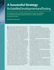
Picosecond Lasers <strong>for</strong><br />
<strong>Single</strong>-<strong>Event</strong> <strong>Effects</strong> Testing<br />
In the past 10 years, Aerospace has developed a state-of-theart<br />
facility that uses picosecond laser pulses to simulate the<br />
transient effects of energetic particles striking microelectronic<br />
devices. This system is used to diagnose radiation-hardened<br />
designs and to validate radiation-hardening techniques <strong>for</strong><br />
mitigating the effects of space radiation on integrated circuits.<br />
Steven Moss and<br />
Stephen LaLumondiere<br />
Microelectronic and optoelectronic<br />
devices used in satellite<br />
systems must operate in<br />
an extremely harsh environment.<br />
Energetic particles can strike sensitive<br />
nodes in devices, causing permanent<br />
damage or transient events. Phenomena<br />
associated with the trail of charge produced<br />
by the strike of a single energetic particle<br />
are commonly referred to, by members of<br />
the radiation-effects community, as singleevent<br />
effects. These can cause temporary<br />
or permanent changes in the state or per<strong>for</strong>mance<br />
of a device.<br />
Testing microelectronics <strong>for</strong> their susceptibility<br />
to single-event effects is typically<br />
done by exposing them to an ion<br />
beam from a particle accelerator. This<br />
method simulates the hostile space environment<br />
fairly well, but can be both costly<br />
and time consuming. To meet the need <strong>for</strong><br />
a cheaper alternative, Aerospace began<br />
20 • Crosslink Summer 2003<br />
The interaction of a picosecond laser pulse with a semiconductor material can generate a high density<br />
of electron-hole pairs (also known as charge carriers), much like the passage of an ionizing particle<br />
through the device.
investigating the feasibility of using laser<br />
pulses to simulate the effects of energetic<br />
particles in 1992.<br />
Thanks to intensive ef<strong>for</strong>ts in the lasertest<br />
community, laser-based testing of microelectronic<br />
devices <strong>for</strong> single-event effects<br />
has gained widespread acceptance in<br />
the radiation-effects community as a useful<br />
complement to traditional testing methods.<br />
Today, the driving <strong>for</strong>ce behind the use<br />
of this technique is the ability to pinpoint<br />
sensitive nodes with submicron accuracy.<br />
Laser Simulation of<br />
Cosmic Ray <strong>Effects</strong><br />
The interaction of a cosmic ray in an integrated<br />
circuit generates a dense electronhole<br />
plasma inside the semiconductor<br />
material; so does the absorption of a<br />
picosecond laser pulse. Both the particle<br />
and laser interactions occur on a short time<br />
scale—much shorter than the response<br />
time of most microelectronic devices. Although<br />
the initial charge profile produced<br />
by absorption of a laser pulse is somewhat<br />
different from that produced by the interaction<br />
of a cosmic ray, both events produce a<br />
highly localized trail of charge capable of<br />
generating single-event effects in microelectronic<br />
devices.<br />
Testing with heavy ions consists of irradiating<br />
the entire device in a particle-beam<br />
accelerator and determining the upsetsensitive<br />
cross section based upon the incident<br />
ion flux and the number of upsets observed.<br />
The technique is global in nature,<br />
generally indicating whether or not an upset<br />
occurred, but not where on the device it<br />
originated. Also, because the technique relies<br />
on random particle strikes over the entire<br />
area of the device, temporal in<strong>for</strong>mation<br />
is lost.<br />
Testing with a pulsed laser provides several<br />
capabilities not offered by particlebeam<br />
testing. For example, the small spot<br />
sizes achievable with a laser and the ability<br />
to precisely position the device relative to<br />
the laser beam allow sensitive device nodes<br />
to be pinpointed with submicron accuracy.<br />
The laser produces no permanent damage<br />
in the device, so repeated measurements<br />
can be made at a single sensitive location.<br />
The laser pulse can also be synchronized<br />
with the clock signal of the device to study<br />
temporal effects on sensitivity to singleevent<br />
phenomena.<br />
The laser system can also be used to verify<br />
operation of test equipment be<strong>for</strong>e embarking<br />
on the more costly journey to an<br />
accelerator facility. Unlike most particlebeam<br />
facilities, the laser facility does not<br />
require devices to be placed in a vacuum<br />
chamber <strong>for</strong> testing, and support electronics<br />
can be located close to the device under<br />
test. This is an extremely important feature<br />
when testing high-speed devices <strong>for</strong> their<br />
susceptibility to single-event transients.<br />
The practicality of this technique is limited<br />
by the inability of the laser light to<br />
penetrate metal layers covering sensitive<br />
device nodes. Complex devices with many<br />
Picosecond<br />
laser pulses<br />
Beamsplitter<br />
Photodetector<br />
Fiber-optic<br />
illuminator<br />
Beamsplitter<br />
layers of metal limit the ability to determine<br />
the amount of incident light on a sensitive<br />
junction; however, other approaches<br />
such as thinning and testing devices from<br />
behind are viable alternates to the standard<br />
front test method.<br />
The Facility<br />
Over the years, various organizations in the<br />
United States have used lasers to simulate<br />
single-event effects, but only Aerospace<br />
and the Naval Research Laboratory currently<br />
possess dedicated laser facilities <strong>for</strong><br />
this work. Researchers in the radiationeffects<br />
community have come to rely upon<br />
these facilities because of the unique capabilities<br />
they provide.<br />
For example, the Aerospace laser test<br />
system can produce a train of pulses at a<br />
variable repetition frequency or operate in<br />
a single-shot mode. The system uses dye<br />
Positioning<br />
system<br />
Microscope<br />
objective<br />
Test item<br />
Video<br />
monitor<br />
Camera<br />
XPOS = 23.3 µm<br />
YPOS = 45.0 µm<br />
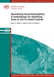
In testing <strong>for</strong> susceptibility to single-event effects, a technique known as mode-locking is used to generate<br />
a train of laser pulses, each of which lasts only a few picoseconds. An electro-optic shutter grabs<br />
individual pulses, which are then focused through a microscope onto the device under test. A camera<br />
attached to the microscope shows the position of the laser beam. Devices are scanned beneath the<br />
laser beam to locate sensitive nodes. High-speed digital oscilloscopes, transient digitizers, and logic<br />
analyzers capture the response of devices to charges generated in the semiconductor material by the<br />
incident laser pulse.<br />
Crosslink Summer 2003 • 21
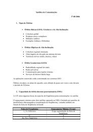
Energy (picojoules)<br />
200<br />
175<br />
150<br />
125<br />
100<br />
75<br />
50<br />
25<br />
0<br />
0<br />
A detailed one-dimensional sensitivity map displaying the threshold laser pulse energy required to induce<br />
latchup in the four-terminal test structure. The inset shows the location and direction of the scan.<br />
The most sensitive location (i.e., the location requiring the least pulse energy <strong>for</strong> latchup) is found near<br />
the edge of the negative-current well. The two double peaks represent where the laser was scanned<br />
over the metal contacts. The metal lines block any incident laser light. The laser spot has a Gaussian<br />
spatial profile with a spot size on the same order as the width of the metal lines. Consequently, there<br />
is always some light that propagates past the metal lines into the device, even when the laser spot is<br />
centered on one of the lines.Thus, the devices can still be latched up by increasing the laser pulse energy;<br />
however, as shown here, this requires a considerable increase in energy.<br />
lasers to generate picosecond optical pulses;<br />
the laser wavelength can be tuned over the<br />
visible spectrum and into the near infrared.<br />
Two wavelengths are generally used at<br />
Aerospace to measure laser-induced<br />
single-event effects. The first, 600 nanometers,<br />
has a penetration depth of about 2<br />
microns in silicon. The second, 815 nanometers,<br />
has a penetration depth of about 12<br />
22 • Crosslink Summer 2003<br />
5<br />
10 15 20 25 30 35 40<br />
Distance (microns)<br />
microns. The ability to vary the penetration<br />
depth allows <strong>for</strong> detailed studies of chargecollection<br />
mechanisms in a variety of devices.<br />
The ability to control the range—and<br />
the energy deposited over that range—is<br />
not easily achievable in accelerator-based<br />
testing. The penetration depth of an energetic<br />
particle depends on both the particle<br />
energy and its mass. In order to test at two<br />
Origins of Laser Testing <strong>for</strong> <strong>Single</strong>-<strong>Event</strong> <strong>Effects</strong><br />
The first published report of using a pulsed laser to simulate the effects of ionizing<br />
radiation on microelectronic devices dates back to 1965. In that study, nanosecond<br />
pulses (10 –9 seconds) from a Q-switched Nd:YAG laser were used to<br />
simulate dose-rate effects (the type of effect that would be encountered from a<br />
nuclear detonation) on integrated circuits.<br />
Although the potential <strong>for</strong> focusing a laser beam onto individual transistors in<br />
more complex devices was also realized at this time, no one thought about<br />
applying this technique to the study of cosmic-ray-induced single-event effects<br />
because no one had yet witnessed single-event effects in microelectronic devices.<br />
In fact, the first confirmed on-orbit upsets from heavy ions were not reported<br />
until 1975. These upsets were attributed to galactic cosmic rays triggering J-K<br />
flip-flops on a communications satellite (a J-K flip-flop is a basic two-state<br />
memory component).<br />
A limited amount of work was per<strong>for</strong>med in this area in the late 1970s and<br />
early 1980s; however, by the mid-1980s, researchers from a number of different<br />
laboratories had opened the investigation into the potential of picosecond laser<br />
pulses <strong>for</strong> simulating cosmic-ray-induced single-event effects in microelectronic<br />
devices. By the latter part of the 1980s, picosecond laser pulses were being<br />
used to simulate transient radiation effects at the Naval Weapons Center, Naval<br />
Research Laboratory, Jet Propulsion Laboratory, and at various defense contractors<br />
and laboratories around the world.<br />
different ranges with particles of the same<br />
linear energy transfer, particles with different<br />
mass are typically required (linear energy<br />
transfer is the amount of energy deposited<br />
per unit length by a particle along<br />
its path through a material). The Aerospace<br />
team that uses the Lawrence Berkeley cyclotron<br />
per<strong>for</strong>ms tests using a variety of<br />
particles with different energies and different<br />
masses, which allows characterization<br />
of most devices over a wide range of linear<br />
energy transfer (see “Heavy-Ion Testing<br />
<strong>for</strong> <strong>Single</strong>-<strong>Event</strong> <strong>Effects</strong>”).<br />
In the Aerospace laser test facility, the<br />
device test fixture is mounted on a<br />
computer-controlled, two-dimensional positioning<br />
system and raster scanned beneath<br />
the laser beam. Positional accuracy<br />
is 0.1 micron. The laser beam is focused<br />
onto the device with a custom-built microscope.<br />
A camera attached to the microscope<br />
allows investigators to observe the<br />
exact location of the laser beam on the device.<br />
Various microscope objectives provide<br />
useful magnifications between 100×<br />
and 1000×, and the spot size of the incident<br />
laser beam can be varied between approximately<br />
1 and 150 microns.<br />
The testing process generally begins by<br />
scanning a device with the large-diameter<br />
laser spot at low magnification to identify<br />
sensitive regions. During this initial scan,<br />
both spatial coordinates and images of the<br />
sensitive regions are recorded.<br />
Once the large-spot scan has been completed,<br />
a tightly focused laser spot at higher<br />
magnification is used to pinpoint sensitive<br />
nodes within the regions identified during<br />
the large-spot scan. The threshold <strong>for</strong><br />
single-event effects can be determined by<br />
reducing the incident pulse energy until<br />
single-event effects are no longer observed.<br />
A fraction of the optical signal is sampled<br />
by a photodiode and monitored on an oscilloscope<br />
<strong>for</strong> calibrating the laser-pulse<br />
energy incident on the device. Thorough<br />
calibration of the system includes measurements<br />
of the reflectance from the semiconductor<br />
surface at sensitive locations.<br />
Aerospace Activities<br />
Early work at Aerospace focused on establishing<br />
a relationship between single-event<br />
effects induced by the pulsed laser and by<br />
energetic particles. For these measurements,<br />
basic four-terminal latchup test<br />
structures were chosen. These structures<br />
are routinely used <strong>for</strong> latchup research and<br />
are the simplest that can be used to study<br />
this phenomenon in complementary metaloxide<br />
semiconductor (CMOS) devices.
Results from these measurements<br />
showed that it was possible to correlate the<br />
thresholds <strong>for</strong> heavy-ion-induced latchup<br />
and laser-induced latchup in CMOS devices<br />
from a number of different vendors.<br />
Additional studies were per<strong>for</strong>med to validate<br />
the effectiveness of various techniques<br />
to produce devices that were “hardened by<br />
design” (see “Designing Integrated Circuits<br />
to Withstand Space Radiation”).<br />
More recently, Aerospace has been investigating<br />
single-event upsets, singleevent<br />
latchup, and single-event transients<br />
in various analog, digital, and mixedsignal<br />
devices.<br />
Transient Testing<br />
<strong>Single</strong>-event transients appear as brief current<br />
spikes that can lead to anomalies in<br />
other components, such as logic circuits,<br />
downstream from the affected component.<br />
They can also propagate through logic<br />
gates in digital integrated circuits and be<br />
captured as upsets by clocked logic.<br />
The commercial demand <strong>for</strong> high-speed,<br />
low-power devices is driving down the<br />
minimum feature sizes in microelectronics.<br />
As a result, single-event transients are<br />
causing greater concern <strong>for</strong> space-systems<br />
engineers. Reduced feature sizes and operating<br />
voltages mean that less charge is required<br />
to generate upsets, and also mean<br />
that modern devices will be fast enough to<br />
respond to single-event transients that were<br />
too short to propagate through older,<br />
slower logic.<br />
Aerospace first reported the use of a<br />
picosecond laser as a diagnostic tool <strong>for</strong><br />
understanding the origins of single-event<br />
transients in analog devices in 1993. Operational<br />
amplifiers, known to experience<br />
single-event transients on orbit, were first<br />
tested with heavy ions at a cyclotron and<br />
then subjected to laser testing to identify<br />
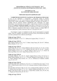
Transient amplitude (volts)<br />
3<br />
2<br />
1<br />
0<br />
–1<br />
–2<br />
–3<br />
–4<br />
–5<br />
1X<br />
3X<br />
8X<br />
0 50 100 150 200<br />
<strong>Single</strong>-event transients from linear integrated circuits can be captured and registered as logical upsets<br />
in digital integrated circuits. The amplitude and width of this transient disturbance is proportional to the<br />
amount of charge collected by the sensitive device node. The use of picosecond lasers <strong>for</strong> this type of<br />
testing has aided in explaining the transient behavior of individual transistors in more complex integrated<br />
circuits. The three transients depicted here show how a single transistor in a high-speed operational<br />
amplifier responds to different amounts of energy deposited by the laser.The greater the amount<br />
of deposited energy, the larger the peak amplitude and width of the disturbance. For simplification, the<br />
energy deposited by the laser pulse has been normalized to the smallest amplitude transient.<br />
the approximate areas of sensitive transistors.<br />
The results showed that the laser<br />
could be used to identify sensitive transistors<br />
and to reproduce the transient behavior<br />
observed during energetic particle<br />
tests.<br />
Since then, pulsed lasers have been used<br />
on numerous occasions to complement a<br />
limited set of particle-beam data and to expand<br />
the knowledge of how device sensitivity<br />
varies under different operating conditions.<br />
To date, laser-based testing has<br />
been used to examine single-event transients<br />
in a variety of analog devices commonly<br />
found in space systems, including<br />
operational amplifiers, comparators, and<br />
mixed-signal components.<br />
Time (nanoseconds)<br />
250<br />
Latchup Testing of<br />
Commercial Parts<br />
Recently, Aerospace collaborated with<br />
researchers from NASA’s Jet Propulsion<br />
Laboratory (JPL) to identify the mechanisms<br />
responsible <strong>for</strong> destructive failures<br />
observed in an analog-to-digital converter<br />
induced by heavy ions during latchup testing.<br />
A substantial number of these devices<br />
suffered catastrophic failures during these<br />
tests, but the complexity of the devices<br />
made it difficult to identify the failure<br />
mode.<br />
By using the pulsed laser, Aerospace was<br />
able to pinpoint the sensitive nodes and<br />
view, in real time, the destructive failure<br />
mode. This allowed the researchers from<br />
Be<strong>for</strong>e and after images showing destructive failure of metal lines in an<br />
analog-to-digital converter as a result of latchup. The highlighted regions<br />
(in the photo on the right) are areas where molten metal was ejected from<br />
the metal line.<br />
Crosslink Summer 2003 • 23
JPL to determine that the current density<br />
from latchup was so great in these converters<br />
that the aluminum metal lines were actually<br />
melting and ejecting molten aluminum<br />
from beneath the metal encapsulant layer.<br />
Once the location of this failure mechanism<br />
had been identified with the pulsed<br />
laser, the devices were reexamined using<br />
heavy-ion irradiation, and the same failure<br />
mode was obvious. The laser tests also provided<br />
direct evidence <strong>for</strong> nondestructive,<br />
latent damage to metal lines and vias subject<br />
to such high-current densities as a result<br />
of latchup. These were the first experiments<br />
in which destructive failures and<br />
latent damage were observed and recorded<br />
in real time.<br />
Aerospace has also tested a number of<br />
complex microprocessors and digital signal<br />
processors. In the case of the Motorola<br />
68302 microprocessor, <strong>for</strong> example,<br />
heavy-ion testing revealed a number of different<br />
single-event upset signatures and indicated<br />
that the device was fairly sensitive<br />
to energetic-particle-induced latchup; however,<br />
observations had not shown this<br />
microprocessor to be prone to latchup on<br />
orbit. The laser was used to probe the different<br />
parts of the microprocessor responsible<br />
<strong>for</strong> these types of effects and pinpoint<br />
the nodes that were sensitive to latchup.<br />
Agreement between the laser-based test<br />
and the heavy-ion test led investigators to<br />
look <strong>for</strong> an alternative explanation <strong>for</strong> the<br />
apparent absence of latchup events on orbit.<br />
They noted that the telemetry data from<br />
the satellite allows checking of the device<br />
current only 0.0002 percent of the time.<br />
They there<strong>for</strong>e concluded that the part<br />
probably is experiencing latchup on-orbit,<br />
but the high-current state is not detectable<br />
because the limited duty factor of the sampling<br />
telemetry makes it highly unlikely<br />
that a high-current event will be detected<br />
be<strong>for</strong>e the system is reset (effectively correcting<br />
the latchup condition).<br />
In another instance, Aerospace assessed<br />
the single-event latchup vulnerability of a<br />
24-bit digital signal processor <strong>for</strong> the Milsatcom<br />
program office. A highly detailed<br />
map of latchup-sensitive locations on this<br />
device was generated, and more than 3700<br />
individual nodes were identified as being<br />
susceptible to laser-induced latchup.<br />
Some of these sites were susceptible at<br />
low linear energy transfer values, which<br />
indicated that the part would probably<br />
experience latchup on orbit. As a result,<br />
researchers concluded that this part would<br />
24 • Crosslink Summer 2003<br />
Volts<br />
Volts<br />
5<br />
4<br />
3<br />
2<br />
1<br />
0<br />
5<br />
4<br />
3<br />
2<br />
1<br />
0<br />
0 5 10 15 20 25 30 35 40 45 50<br />
Time (nanoseconds)<br />
By synchronizing the clock frequency of a device with the laser pulse, the temporal dependence of<br />
single-event upset on clock cycle can be investigated using a pulsed laser.The upper traces in this figure<br />
show the laser pulse arriving just prior to the falling edge of the clock signal and no upset observed<br />
at the device output; however, whenever the laser pulse arrives slightly after the falling edge of the<br />
clock wave<strong>for</strong>m, the next clock cycle is phase shifted, or delayed in time by one-half of the clock period.<br />
not be an acceptable candidate <strong>for</strong> the<br />
mission under consideration.<br />
Validating Hardened Designs<br />
Heavy-ion tests on memory cells designed<br />
to be resistant to single-event effects generated<br />
both single-event upset and singleevent<br />
latchup. In accelerator-based testing,<br />
little in<strong>for</strong>mation could be extracted from<br />
these tests because the latchup threshold<br />
was only slightly higher than the upset<br />
threshold. Irradiation of the entire device<br />
produced latchup and upsets randomly;<br />
however, in many instances, the device experienced<br />
upset but was then driven into<br />
latchup be<strong>for</strong>e in<strong>for</strong>mation about the upset<br />
could be retrieved. Consequently, <strong>for</strong> devices<br />
such as these, it was not possible to<br />
cleanly extract in<strong>for</strong>mation about the upset<br />
threshold and cross section using the standard,<br />
heavy-ion test procedures.<br />
Because the laser beam can be focused<br />
onto a single node, Aerospace used the<br />
pulsed laser to identify the locations responsible<br />
<strong>for</strong> latchup and then conducted a<br />
detailed analysis of the device layout to<br />
identify the root cause. Laser testing was<br />
also used to identify the nodes responsible<br />
<strong>for</strong> the upset, without any interference<br />
from the latchup problem. Electrical simulations<br />
of the circuit then helped reveal an<br />
unexpected dual-node upset mechanism.<br />
The upset was a result of simultaneous<br />
charge collection at two sensitive locations.<br />
Understanding the mechanisms responsible<br />
<strong>for</strong> the high sensitivity to single-event<br />
effects allowed <strong>for</strong> circuit design changes<br />
that improved the memory cells’ resistance<br />
to single-event effects.<br />
Similarly, heavy-ion single-event testing<br />
of an application-specific integrated circuit<br />
identified a susceptibility both to singleevent<br />
latchup and single-event upset. The<br />
linear energy transfer threshold <strong>for</strong> inducing<br />
latchup was low enough to prompt the<br />
use of the pulsed laser to identify areas on<br />
the chip that were responsible <strong>for</strong> these<br />
events. The results from these measurements<br />
were provided to the contractor, and<br />
the circuit was redesigned with appropriate<br />
modifications. Subsequent testing<br />
showed no evidence of latchup.
The use of a large-diameter laser beam allows <strong>for</strong> rapid identification of<br />
regions in complex integrated circuits that are susceptible to single-event<br />
effects. A tightly focused laser beam, on the order of a micron in diameter,<br />
can then be used to precisely pinpoint sensitive junctions at the transistor<br />
level. This technique provides valuable in<strong>for</strong>mation to the designer who is<br />
interested in understanding and mitigating single-event effects in spaceborne<br />
microelectronics.<br />
A radiation-hardened version of a 32-bit<br />
digital signal processor was also tested <strong>for</strong><br />
laser-induced latchup and compared with<br />
the corresponding commercial version.<br />
During heavy-ion testing, the hardened devices<br />
exhibited no latchup <strong>for</strong> effective linear<br />
energy transfer values as high as 120<br />
MeV-cm 2 /mg.<br />
The commercial version, on the other<br />
hand, exhibited latchup during heavy-ion<br />
testing at an effective linear energy transfer<br />
value of only 12 MeV-cm 2 /mg. In fact,<br />
laser testing allowed the identification of<br />
more than 60 single-event latchup locations<br />
on this device. The same locations<br />
on the hardened version were then interrogated<br />
with the laser, but no latchup was<br />
observed. This result provided confidence<br />
in the radiation-hardened design and further<br />
confirmed the effectiveness of the<br />
laser <strong>for</strong> latchup screening of hardened<br />
devices.<br />
Continuing Investigations<br />
Aerospace is involved in collaborative research<br />
ef<strong>for</strong>ts to study novel approaches<br />
<strong>for</strong> hardening commercially available integrated<br />
circuits against single-event latchup.<br />
Additional ef<strong>for</strong>ts seek to gauge the space<br />
suitability of commercially available devices<br />
that take advantage of advanced manufacturing<br />
processes. The picosecond-laser<br />
facility is also being used to study the effectiveness<br />
of various design strategies <strong>for</strong><br />
mitigating the effects of single-event transients<br />
in digital integrated circuits.<br />
High-speed integrated circuits are transitioning<br />
from silicon-based semiconductors<br />
to compound semiconductors, such as gallium<br />
arsenide, indium phosphide, and<br />
silicon germanium. Aerospace investigation<br />
of these devices will include the picosecond<br />
laser system to help characterize<br />
their sensitivity to single-event effects.<br />
While laser-induced single-event effect<br />
testing will not replace conventional<br />
particle-beam testing, it has become a wellestablished<br />
technique <strong>for</strong> providing a better<br />
understanding of the nature of single-event<br />
effects in complex modern microelectronic<br />
devices and <strong>for</strong> validating designhardening<br />
methods to mitigate single-event<br />
effects in these devices.<br />
Further Reading<br />
D. Binder, et al., “Satellite Anomalies from<br />
Galactic Cosmic Rays,” IEEE Transactions<br />
on Nuclear Science, Vol. 22, pp. 2675–2680<br />
(1975).<br />
S. H. Crain, S. D. LaLumondiere, S. W. Miller,<br />
W. R. Crain, K. B. Craw<strong>for</strong>d, S. J. Hansel, R.<br />
Koga, and S. C. Moss, “Comparison of Flight<br />
and Ground Data <strong>for</strong> Radiation-Induced High<br />
Current States in the 68302 Microprocessor,”<br />
2000 IEEE NSREC Data Workshop Record, pp.<br />
85–88 (00TH8527).<br />
D. H. Habing, “The Use of Lasers to Simulate<br />
Radiation Induced Transients in Semiconductor<br />
Devices and Circuits,” IEEE Transactions<br />
on Nuclear Science, NS 12, pp.<br />
91–100 (1965).<br />
R. Koga, S. D. Pinkerton, S. C. Moss, D. C.<br />
Mayer, S. LaLumondiere, S. J. Hansel, K. B.<br />
Craw<strong>for</strong>d, and W. R. Crain, “Observation of<br />
<strong>Single</strong> <strong>Event</strong> Upsets in Analog Microcircuits,”<br />
IEEE Transactions on Nuclear Science,Vol. 40,<br />
pp. 1838–1844 (1993).<br />
R. Koga, S. H. Penzin, K. B. Craw<strong>for</strong>d, W. R.<br />
Crain, S. C. Moss, S. D. Pinkerton, S. D. LaLumondiere,<br />
and M. C. Maher, “<strong>Single</strong> <strong>Event</strong> Upset<br />
Sensitivity Dependence of Linear Integrated<br />
Circuits on Bias Conditions,” IEEE Transactions<br />
on Nuclear Science, Vol. 44, pp. 2325–<br />
2332 (1997).<br />
D. McMorrow et al., “Application of a Pulsed<br />
Laser <strong>for</strong> Evaluation and Optimization of SEU-<br />
Hard Designs,” IEEE Transactions on Nuclear<br />
Science,Vol. 47, pp. 559–563 (2000).<br />
J. S. Melinger, et al., “Pulsed Laser-Induced<br />
<strong>Single</strong> <strong>Event</strong> Upset and Charge Collection Measurements<br />
as a Function of Optical Penetration<br />
Depth,” Journal of Applied Physics,Vol. 84, pp.<br />
690–703 (1998).<br />
G. C. Messenger and M. S. Ash, <strong>Single</strong> <strong>Event</strong><br />
Phenomena (Chapman-Hall, New York, 1997).<br />
T. F. Miyahira, A. H. Johnston, H. N. Becker,<br />
S. D. LaLumondiere, and S. C. Moss, “Catastrophic<br />
Latchup in CMOS Analog-to-Digital<br />
Converters,” IEEE Transactions on Nuclear<br />
Science,Vol. 48, pp. 1833–1840 (2001).<br />
S. C. Moss et al., “Correlation of Picosecond<br />
Laser-Induced Latchup and Energetic Particle-<br />
Induced Latchup in CMOS Test Structures,”<br />
IEEE Transactions on Nuclear Science, Vol. 42,<br />
pp. 1948–1956 (1995).<br />
J. V. Osborn, D. C Mayer, R. C. Lacoe, S. C.<br />
Moss, and S. D. LaLumondiere, “<strong>Single</strong> <strong>Event</strong><br />
Latchup Characteristics of Three Commercial<br />
CMOS Processes,” Proceedings, 7th NASA<br />
Symposium on VLSI Design (1998).<br />
R. Valezco, T. Calin, M. Nicolaidis, S. C. Moss,<br />
S. D. LaLumondiere, V. T. Tran, and R. Koga,<br />
“SEU-Hardened Storage Cell Validation Using<br />
a Pulsed Laser,” IEEE Transactions on Nuclear<br />
Science,Vol. 43, pp. 2843–2848 (1996).<br />
Crosslink Summer 2003 • 25
Heavy-Ion Testing<br />
<strong>for</strong> <strong>Single</strong>-<strong>Event</strong> <strong>Effects</strong><br />
The most reliable way to reproduce the space-particle<br />
environment on Earth is with a particle accelerator such<br />
as a cyclotron. Aerospace has conducted numerous tests<br />
measuring the susceptibility of microelectronic devices to<br />
single-event effects.<br />
Susan Crain and<br />
Rocky Koga<br />
26 • Crosslink Summer 2003<br />
The liftoff of the Atlas Centaur<br />
launch vehicle seemed pictureperfect:<br />
The rocket completed its<br />
ascent and successfully deployed<br />
its payload to its intended orbit. What was<br />
not immediately apparent was that some<br />
bits in the computer memory were altered<br />
as the vehicle flew through a region of<br />
space dense with energetic protons. In this<br />
case, the errors were automatically detected<br />
and corrected by the computer—but<br />
could the launch team always count on<br />
such good <strong>for</strong>tune?<br />
<strong>Event</strong>s such as this have led to the realization<br />
that spaceborne microcircuits are<br />
vulnerable to galactic cosmic rays and<br />
trapped protons. Since the discovery of socalled<br />
“single-event upsets” in 1975, scientists<br />
have sought to characterize the spaceradiation<br />
environment in greater detail and<br />
understand its interactions with microelectronics.<br />
Ideally, the study of space-radiation effects<br />
should be conducted in a manner that<br />
approximates, as closely as possible, the<br />
space-radiation environment. The most reliable<br />
test would use all of the same ion<br />
types that are found in space and allow<br />
measurement over a wide energy range <strong>for</strong><br />
each. But such a test would be prohibitively<br />
expensive. A more practical approach<br />
is to use a medium-energy particle<br />
accelerator to simulate galactic cosmic<br />
rays and trapped protons in space-radiation<br />
environments.<br />
The ability of an ionized particle to interact<br />
with materials is a function of its linear<br />
energy transfer (LET) value. LET is essentially<br />
the measure of ionizing energy<br />
deposited in a material per distance traveled,<br />
generally rendered in millions of<br />
electron volts per square centimeter per<br />
milligram (MeV-cm 2 /mg). For particles in<br />
space, the range of LET varies primarily<br />
from a few hundredths to just under 100<br />
MeV-cm 2 /mg. Particles with low LET values<br />
are far more abundant than particles<br />
with high LET. Thus, in investigating a<br />
particular device, researchers seek to find<br />
the threshold value and to determine the<br />
magnitude of sensitivity at large LET values.<br />
Such an investigation requires an accelerator<br />
capable of generating many particles<br />
with different LET values.<br />
The Facility<br />
The choice of accelerator is based on its capability<br />
to produce ions with a reasonable<br />
particle range <strong>for</strong> a wide range of LET values.<br />
Other factors include the ease of use<br />
and cost of operation. Aerospace has traditionally<br />
used the 88-inch cyclotron at<br />
Lawrence Berkeley National Laboratory.<br />
This cyclotron routinely and reliably accelerates<br />
ion species as light as protons and<br />
as heavy as gold. To achieve high energy<br />
without losing high intensity, it employs a<br />
sector-focused design. A process known as<br />
electron cyclotron resonance is used to<br />
generate the ion source; the ions are then<br />
injected into the cyclotron <strong>for</strong> acceleration.<br />
This technique allows continuous operation<br />
of the cyclotron <strong>for</strong> up to several<br />
weeks. Also important, it allows researchers<br />
to modify the ion intensity with<br />
the push of a button.<br />
The Berkeley cyclotron can produce<br />
several ion species of various LET values.<br />
A typical test run might use a half dozen<br />
different ion types ranging in mass from<br />
boron to xenon, each capable of penetrating<br />
to different depths within the target device.<br />
The ions can be switched in a matter<br />
of seconds, making single-event effects<br />
testing highly efficient.<br />
The beam diameter is about 7.6 centimeters,<br />
within which the target position is determined<br />
by a laser targeting system. The<br />
beam may be directed to a small section of
Test boards often accommodate several devices<br />
<strong>for</strong> testing, eliminating the need to vent<br />
the chamber to change the parts. The control<br />
software <strong>for</strong> the motion system logs the<br />
unique spatial in<strong>for</strong>mation <strong>for</strong> each part so it<br />
is always centered in the beam line even<br />
when it is angled to achieve effective LETs.<br />
a microcircuit or to a large detector. The<br />
ion flux range is between a few particles to<br />
a few hundred thousand particles per<br />
square centimeter per second. A low flux is<br />
used <strong>for</strong> sensitive devices, and a high flux<br />
is used to check <strong>for</strong> rare events. A surfacebarrier<br />
detector <strong>for</strong> energy measurement<br />
and a position-sensitive detector serve to<br />
identify ion species, energy, and uni<strong>for</strong>mity.<br />
A diagnostic/dosimetry apparatus<br />
verifies that the beam is suitable <strong>for</strong> the<br />
type of testing being per<strong>for</strong>med.<br />
The irradiation chamber measures 96.5<br />
× 99 × 116.8 centimeters. Vacuum is controlled<br />
by a high-capacity system of pumps<br />
capable of evacuating the chamber in about<br />
four minutes. This makes sample changes<br />
quick and easy. A mechanized, remotecontrolled<br />
system moves individual test<br />
samples in and out of the beam and<br />
changes beam-exposure angles. Changing<br />
the beam-exposure angle effectively<br />
changes the charge deposition in the sensitive<br />
region of a microcircuit. Charge deposition<br />
is related to the concept of “effective<br />
LET,” which is calculated by multiplying<br />
the LET of the incident ion by the secant of<br />
the angle between the incident beam and<br />
the chip-surface normal.<br />
Test Methodology<br />
The facility at Lawrence Berkeley National<br />
Laboratory has been used to test all<br />
kinds of devices and circuits. In the past,<br />
some electronics manufacturers maintained<br />
separate production lines <strong>for</strong><br />
radiation-hardened devices, and the cyclotron<br />
was used to examine these parts.<br />
With the subsequent increase in commercial<br />
space systems, designers sought to use<br />
cheaper off-the-shelf devices, and the<br />
cyclotron was used to assess their potential<br />
<strong>for</strong> particular missions. More recently, the<br />
cyclotron has been used to evaluate a technique<br />
known as “radiation hardening by<br />
design,” which uses specific design principles<br />
to increase the radiation resistance of<br />
components produced via standard commercial<br />
foundries.<br />
The Aerospace single-event effects testing<br />
program has investigated both military<br />
and commercial products. Often, a commercial<br />
device will be tested to determine<br />
whether it can pass<br />
as a rad-hard product<br />
according to military<br />
specifications. Other<br />
testing ef<strong>for</strong>ts involve<br />
the characterization<br />
of boardlevel<br />
circuits <strong>for</strong><br />
space systems using<br />
commercially available<br />
parts.<br />
Ground testing of<br />
devices <strong>for</strong> use in<br />
military, commercial,<br />
and research ef<strong>for</strong>ts<br />
is done using<br />
specially designed<br />
testers. The process<br />
involves exposing a<br />
part to a particle<br />
beam while monitoring<br />
its function.<br />
By counting the<br />
number of upsets<br />
and knowing how many particles passed<br />
through the part, investigators can calculate<br />
the likelihood that a particle strike will<br />
cause a single-event effect. Such calculations<br />
may be used to produce a set of sensitivity<br />
curves <strong>for</strong> a microcircuit type, which<br />
can in turn be used to estimate the upset<br />
rate of the microcircuits <strong>for</strong> various orbits.<br />
A microcircuit may<br />
respond differently<br />
depending on factors<br />
such as case<br />
temperature, clock<br />
speed, and cumulative<br />
total dose. In<br />
addition, the vulnerability<br />
<strong>for</strong> one microcircuit<br />
type to<br />
different types of<br />
single-event effects<br />
varies at different<br />
energy values <strong>for</strong><br />
heavy ions and protons.<br />
These are<br />
some of the many<br />
parameters that<br />
must be carefully<br />
monitored.<br />
Ion<br />
In general, a device is first tested <strong>for</strong> destructive<br />
single-event effects such as<br />
latchup, burnout, and gate rupture. If the<br />
device does not display latchup, <strong>for</strong> example,<br />
or if the onset <strong>for</strong> latchup is at a high<br />
enough LET value to be tolerable <strong>for</strong> the<br />
particular mission, then the device will be<br />
tested <strong>for</strong> nondestructive effects.<br />
Energy LET Range in silicon<br />
(MeV) (MeV-cm 2 /mg) (microns)<br />
11<br />
B +3 108.2 0.89 323<br />
18<br />
O +5 183.5 2.19 228<br />
22<br />
Ne +6 216.3 3.44 179<br />
40<br />
Ar +11 400 9.88 129<br />
51<br />
V +14 508.3 14.8 116<br />
65<br />
Cu +18 659.2 21.6 108<br />
73<br />
Ge +20 724.7 25.37 104<br />
86<br />
Kr +24 886 30.0 111<br />
98<br />
Mo +27 983.6 38 102<br />
136<br />
Xe +37 1330 53.7 104<br />
136<br />
Xe +38 1403.4 53.6 110<br />
Ten-MeV-per-nucleon particles are used more frequently with parts that<br />
cannot be easily delidded. Often, parts such as DRAMs need to be lapped<br />
from the back side of the die to avoid the lead frame, so the beam needs to<br />
have a greater range to pass through the sensitive regions. Berkeley is developing<br />
still more penetrating cocktails of ions.<br />
Crosslink Summer 2003 • 27
The chamber is designed to accommodate large systems as well as<br />
single boards. This instrument is using the monoenergetic particle<br />
beams to calibrate its detectors be<strong>for</strong>e flight.<br />
When assessing risk, the designer or<br />
program manager needs to consider the<br />
single-event effect data in the context of the<br />
circuit features and the intended mission.<br />
For instance, single-event latchup can be<br />
mitigated (rendered nondestructive) by<br />
watchdog circuits that cycle power when a<br />
current limit is reached; thus, a somewhat<br />
sensitive device might be considered suitable<br />
<strong>for</strong> a given mission provided that such<br />
watchdog circuits are included. However,<br />
because microelectronics are getting more<br />
complex, with denser and larger designs,<br />
such circuits might not be feasible. Some<br />
complex device architectures divide the circuits<br />
into sections powered independently<br />
using different supply voltages. In such<br />
cases, setting an appropriate current limit<br />
becomes a challenge, and may prohibit the<br />
use of a device in a particular orbit.<br />
For nondestructive effects<br />
in a complex microcircuit,<br />
fully characterizing<br />
a device type takes<br />
about 12 to 16 hours of<br />
beam time. If the part is<br />
vulnerable to destructive<br />
effects such as gate rupture<br />
and burnout, the testing<br />
can take even longer.<br />
In more complex devices,<br />
single-event upset sensitivity<br />
in different areas of<br />
the circuit may vary, and<br />
the effects might have different<br />
onsets with respect<br />
to effective LET. Fortunately,<br />
the single-event upset<br />
will usually have a different<br />
signature <strong>for</strong> the<br />
different circuit elements.<br />
Separation of the effects<br />
can happen, but the time it<br />
takes to characterize the<br />
device increases.<br />
Testing Innovations<br />
Through the years, Aerospace<br />
has developed specialized<br />
testers <strong>for</strong> characterizing<br />
a wide variety of<br />
devices. The most recent is<br />
the Aerospace <strong>Single</strong><br />
<strong>Event</strong> Tester (ASSET),<br />
which provides a generalpurpose<br />
interface <strong>for</strong> evaluating<br />
the single-event effect<br />
susceptibility of a<br />
wide variety of complex<br />
microcircuits. It employs<br />
two general test methods—the memory<br />
test and the sequence test.<br />
In memory-test mode, the system treats<br />
the device-under-test like a typical memory<br />
with some control lines, address lines,<br />
and data lines. The tester writes a known<br />
pattern to an array of addresses while the<br />
device is not being irradiated, and then<br />
reads it back to ensure successful writing.<br />
Then, while the device is exposed to the<br />
particle beam, the tester continuously reads<br />
the memory locations and compares them<br />
to what was written. Any discrepancy in a<br />
bit location is counted as an error. The<br />
tester communicates the error, the address<br />
location, and the cycle count to the host<br />
computer. Later, this stored in<strong>for</strong>mation is<br />
analyzed <strong>for</strong> single-bit upsets, addressing<br />
errors, multiple-bit upsets, and stuck-bit errors.<br />
The error is corrected in the device,<br />
and the test continues. The flux of the beam<br />
is kept low enough to keep the errorhandling<br />
process manageable.<br />
The sequence-test mode is used <strong>for</strong> a<br />
broader type of test. In this case, a sequence<br />
of patterns is stored temporally<br />
while the device is undergoing a normal<br />
function, without irradiation. This recorded<br />
pattern is then compared with the device<br />
outputs during exposure to the particle<br />
beam. This is the mode used to test more<br />
complicated microelectronics such as<br />
microprocessors, digital signal processors,<br />
and field-programmable gate arrays. In this<br />
way, the device can be running specialized<br />
programs designed to exercise particular<br />
sections such as the arithmetic logic unit or<br />
the cache, or application-specific programs.<br />
The tester can monitor up to 512<br />
signals at 7 megahertz and can analyze patterns<br />
up to 64,000 words deep. The test<br />
protocol is set in firmware on ASSET under<br />
control from a host computer interfaced<br />
via an in-house specialized parallel<br />
bus protocol.<br />
Recently, dynamic random-access memories<br />
(DRAMs) have attracted the attention<br />
of space system designers because of their<br />
high storage capacity. These and other<br />
complex devices such as synchronous<br />
DRAMs, microprocessors, digital-signal<br />
processors, flash memories, and even<br />
analog-to-digital and digital-to-analog converters<br />
have control registers that can be<br />
upset by radiation. Error detection and correction<br />
schemes can help mitigate singleevent<br />
upset in memories, but if the control<br />
circuits experience single-event upset, then<br />
the function of the device can be completely<br />
impaired. The designer using a<br />
DRAM <strong>for</strong> a space application has many<br />
choices about how to implement operational<br />
modes such as “idle” and “refresh.”<br />
The selected implementation can affect the<br />
device’s radiation sensitivity. Aerospace<br />
has used ASSET to evaluate such devices.<br />
For one program, Aerospace exhaustively<br />
tested synchronous DRAMs not just from a<br />
number of manufacturers <strong>for</strong> comparison,<br />
but also in many different configurations,<br />
identifying the most robust scheme <strong>for</strong><br />
writing, reading, and refreshing. Based on<br />
this data, the customer was able to redesign<br />
the control circuit and successfully implement<br />
a high-capacity memory design.<br />
ASSET can distribute four different<br />
power supplies to as many as 32 different<br />
devices at a time. The supplies are floating<br />
with respect to ground, allowing <strong>for</strong><br />
28 • Crosslink Summer 2003
The motion system on which the microelectronics being studied are mounted allows the user easy access.The<br />
control software will position the parts normal to the beam at the start of a run.The beam enters<br />
the chamber through the lower hole at the back wall. The chamber has several ports with various<br />
connector types available on interchangeable flanges.<br />
inverted (negative) voltages as required.<br />
ASSET can also power thermoelectric<br />
coolers or heaters and monitor temperature.<br />
A cold plate is available <strong>for</strong> cooling<br />
of the test devices such as emitter-coupled<br />
logic parts or high-power devices like<br />
power converters. The devices to be tested<br />
are built onto daughter cards with a standard<br />
interface to the test head. This allows<br />
Cross section (cm 2 /device)<br />
1.0E+01<br />
1.0E+00<br />
1.0E–01<br />
1.0E–02<br />
1.0E–03<br />
1.0E–04<br />
1.0E–05<br />
1.0E–06<br />
0<br />
SEU, SN1<br />
SEU, SN8<br />
SEFI (patch), SN3<br />
SEFI (address), SN1<br />
many different devices with varying<br />
power, control, and interface requirements<br />
to be tested with the same basic system.<br />
The entire apparatus was designed to fit inside<br />
a vacuum chamber with the devices<br />
under test, enhancing signal integrity by<br />
eliminating long cables.<br />
Aerospace is updating ASSET to make<br />
it more portable. It will be about the size of<br />
Current increase, SN2<br />
Current increase, SN3<br />
SEUs due to “light ions”<br />
10 20 30 40 50 60 70<br />
LET (MeV– cm 2 /mg)<br />
This graph charts the sensitivity of a 256-megabit synchronous dynamic random-access memory<br />
(SDRAM) to heavy ions at 4.5 MeV per nucleon. The testing regimen looked <strong>for</strong> single-event upsets<br />
(SEU), single-event functional interrupts (SEFI), and stuck-bit effects. SEFI included errors to a<br />
patch in the memory, errors to consecutive address locations, and errors accompanying an increase<br />
in bias current.<br />
a tackle box and will be faster and better<br />
able to handle low-voltage devices. It has<br />
also been designed to accommodate even<br />
more varieties of DRAMs, flash memories,<br />
and other memory types.<br />
Future Trends<br />
The first heavy-ion tests at Berkeley in<br />
1979 immediately led to the discovery of<br />
single-event latchup. Aerospace investigators<br />
were the first to identify several other<br />
kinds of single-event phenomena in various<br />
types of microcircuits. They include<br />
single-event snapback, single-event transients,<br />
single-word multiple-bit upset, and<br />
stuck-bits effect.<br />
Despite this knowledge, microcircuits occasionally<br />
experience anomalies in space—<br />
often because of a lack of preflight investigation<br />
of radiation effects. When this<br />
happens, Aerospace may be called in to assist<br />
the anomaly investigation. Such ef<strong>for</strong>ts<br />
are necessary postlaunch activities; however,<br />
the trend is to assess the sensitivity of<br />
microcircuits to single-event effects prior to<br />
deployment in space. Designers and program<br />
managers are increasingly aware that a<br />
systematic investigation of all microcircuits<br />
is essential to ensure mission success—and<br />
prevention of single-event effects through<br />
component testing at development stages is<br />
perhaps the most cost-effective approach.<br />
As the microcircuits in space systems grow<br />
ever more complex, ground-based heavyion<br />
testing of spaceborne microcircuits becomes<br />
all the more essential.<br />
Further Reading<br />
R. Burger, D. J. Clark, E. Close, and H. Kim,<br />
“Machine Development at the Berkeley 88-inch<br />
Cyclotron,” IEEE Transactions on Nuclear Science,Vol.<br />
13, p. 364 (1966).<br />
R. Koga and W. A. Kolasinski, “Heavy-Ion Induced<br />
<strong>Single</strong> <strong>Event</strong> Upsets of Microcircuits: A<br />
Summary of The Aerospace Corporation Test<br />
Data,” IEEE Transactions on Nuclear Science,<br />
Vol. 31, pp. 1190–1195 (1984).<br />
R. Koga, “<strong>Single</strong>–<strong>Event</strong> Effect Ground Test Issues,”<br />
IEEE Transactions on Nuclear Science,<br />
Vol. 43, pp. 661–670 (1996).<br />
W. A. Kolasinski et al., “Simulation of Cosmic-<br />
Ray Induced Soft Errors and Latchup in Integrated-Circuit<br />
Computer Memories,” IEEE<br />
Transactions on Nuclear Science, Vol. 26, pp.<br />
5087– 5091 (1979).<br />
Z. Xie, C. M. Lyneis, R. S. Lam, and S. A.<br />
Lundgren, “Enhanced ECR Ion Source Per<strong>for</strong>mance<br />
with an Electron Gun,” Review of Scientific<br />
Instruments, Vol. 62, no. 3, pp. 775–778<br />
(1991).<br />
Crosslink Summer 2003 • 29
Designing Integrated Circuits to<br />
Withstand Space Radiation<br />
The high cost of maintaining dedicated foundries to create<br />
space electronics has motivated an exploration of alternatives<br />
<strong>for</strong> next-generation space systems. One approach in particular—the<br />
use of design techniques to mitigate the effects of<br />
space radiation on integrated circuits—is gaining wider<br />
acceptance.<br />
Donald C. Mayer and<br />
Ronald C. Lacoe<br />
30 • Crosslink Summer 2003<br />
The market <strong>for</strong> satellite components<br />
is small compared with the<br />
consumer microelectronics market,<br />
and manufacturers of integrated<br />
circuits have very little incentive to<br />
develop parts specifically <strong>for</strong> space applications.<br />
This presents a problem <strong>for</strong> satellite<br />
designers because space electronics<br />
must operate in an environment that is<br />
vastly different from what is seen on Earth.<br />
Space electronics are continually bombarded<br />
by energetic plasmas, particles, and<br />
other <strong>for</strong>ms of radiation from the sun and<br />
galactic sources. This radiation can cause<br />
unpredictable spacecraft anomalies, and<br />
mission success can depend on how well<br />
the onboard electronics resist its effects.<br />
Components specifically designed to tolerate<br />
this environment are said to be “radiation<br />
hardened,” or simply “rad hard.”<br />
During the past three decades, several<br />
companies have developed manufacturing<br />
processes to produce a range of rad-hard<br />
electronic products. These processes are<br />
somewhat different from the ones used in<br />
commercial foundries because they<br />
include a few modified process steps that<br />
produce circuits with greater radiation<br />
resistance. These parts are more expensive<br />
than their commercial counterparts<br />
and have lagged several generations<br />
behind in terms of processing speed,<br />
power, and size. Moreover, many companies<br />
that were in the business of supplying<br />
rad-hard components a decade ago have<br />
dropped out of the market. Only two remain<br />
active today.<br />
Faced with rising costs and decreasing<br />
availability of space-qualified electronic<br />
parts, designers have been searching <strong>for</strong><br />
alternatives to the traditional dedicated radhard<br />
foundry approach. One strategy in<br />
particular has been gaining popularity in<br />
recent years. Known as radiation hardening<br />
by design (RHBD), this approach relies<br />
solely on circuit design techniques to<br />
mitigate the damage, functional upsets, and<br />
data loss caused by space radiation.<br />
Aspects of this approach have been in<br />
use <strong>for</strong> some time, but most frequently in<br />
combination with dedicated rad-hard manufacturing<br />
facilities. More recently, a number<br />
of research institutions and corporations<br />
have demonstrated the basic<br />
feasibility of RHBD using standard commercial<br />
foundries; however, to satisfy the<br />
military’s need <strong>for</strong> a wide range of part<br />
types and hardness levels, a self-sustaining<br />
RHBD infrastructure must be established,<br />
and the RHBD approach must be proven<br />
robust enough to use without some degree<br />
of fabrication process control. Aerospace is<br />
working to develop this infrastructure<br />
while demonstrating the efficacy of designhardening<br />
techniques.<br />
Major Concerns<br />
Two types of space radiation are of particular<br />
concern <strong>for</strong> spacecraft electronics designers.<br />
The first, known as the total ionizing<br />
dose, represents the cumulative effect<br />
of many particles hitting a device throughout<br />
the course of its mission life, slowly degrading<br />
the device until it ultimately fails.<br />
The second involves high-energy particles<br />
that penetrate deep into materials and components,<br />
leaving a temporary trail of free<br />
charge carriers in their wake. If these particles<br />
hit vulnerable spots in the circuit, they<br />
can produce adverse effects, described<br />
generically as “single-event effects.”
Each die on this semiconductor<br />
wafer features early radiationhardening-by-design<br />
techniques.<br />
One type of<br />
electronic component<br />
often found<br />
aboard a satellite is the complementary<br />
metal-oxide semiconductor<br />
(CMOS) integrated circuit. CMOS devices<br />
use the simultaneous flow of both<br />
electron and hole currents through transistors<br />
and logic gates. (A “hole” is a quantum<br />
mechanical concept that is generally<br />
modeled as a “missing” electron in the<br />
semiconductor lattice.) The transistors<br />
that carry these negative and positive currents<br />
need to be isolated from each other;<br />
this is where space radiation can interfere.<br />
Total Dose <strong>Effects</strong><br />
The manufacturing processes used to<br />
build commercial electronic components<br />
in the 1970s and 1980s were severely inadequate<br />
to meet the needs of the space<br />
community. But as commercial CMOS<br />
processes have advanced, the inherent radiation<br />
resistance of these devices has improved—and<br />
thus, the RHBD approach has<br />
become more feasible. For example, the<br />
current that flows through CMOS transistors<br />
is governed by a low-voltage gate over<br />
each device, isolated by a layer of oxide.<br />
These<br />
insulating<br />
layers can develop<br />
a charge after<br />
long exposure to ionizing radiation, and<br />
this charge can affect the flow of current<br />
through the device; but as circuits have<br />
shrunk, the thicknesses of these insulating<br />
layers have decreased, presenting less opportunity<br />
<strong>for</strong> charge buildup.<br />
More problematic are the radiationinduced<br />
increases in leakage current—unregulated<br />
current flowing across unintended<br />
areas of the semiconductor. When leakage<br />
current bypasses the transistor’s isolated regions,<br />
it degrades the distinguishability of<br />
the transistor’s “on” and “off” states. Leakage<br />
also increases the circuit’s background<br />
current, or the amount of current flowing<br />
when the device is in a quiescent state. Such<br />
an increase, multiplied by the tens of millions<br />
of switches in each circuit, can drive<br />
up power consumption, increasing heatdissipation<br />
needs and prematurely draining<br />
the power source of the satellite. In an extreme<br />
case, the isolation between discrete<br />
components can also be lost, rendering the<br />
circuit useless.<br />
The edges of the transistors<br />
where the thin gate oxide abuts<br />
the much thicker field oxide,<br />
which covers and insulates the<br />
border regions of the semiconductor,<br />
are also prone to leakage<br />
in a radiation environment. The<br />
process traditionally used to manufacture<br />
the transistor borders can induce<br />
significant material stress, which may facilitate<br />
the increase in leakage current when<br />
exposed to radiation. The newest isolationoxide<br />
manufacturing processes impart less<br />
stress and seem to have achieved a greater<br />
inherent radiation resistance.<br />
Aerospace has been testing the total-dose<br />
hardness of various commercially available<br />
CMOS manufacturing processes since<br />
1995 by building test devices and irradiating<br />
them in a cobalt-60 radiation chamber.<br />
The latest results are encouraging. In some<br />
tests, several commercial CMOS devices<br />
withstood more than 100 kilorads of totaldose<br />
radiation, which is adequate <strong>for</strong> some<br />
space missions. Still, this level of inherent<br />
total-dose hardness may not be sufficient<br />
<strong>for</strong> many space applications. In these cases,<br />
additional immunity can be obtained using<br />
RHBD techniques.<br />
For example, Aerospace and other companies<br />
have shown that total-dose effects<br />
can be mitigated by designing transistors in<br />
an enclosed shape, thereby eliminating the<br />
edges that can trigger current leakage<br />
along the borders of conventional transistors.<br />
Current flows from the center to the<br />
outside of these devices, making them<br />
immune to edge leakage current, but<br />
requiring a larger area <strong>for</strong> each transistor.<br />
Crosslink Summer 2003 • 31
Furthermore, transistor-to-transistor leakage<br />
can be reduced by incorporating guard<br />
bands around individual transistors or<br />
groups of transistors. Other novel techniques<br />
are being applied to conventional<br />
transistor switches to boost their immunity<br />
to total ionizing dose radiation. These techniques<br />
consume area in the design, thereby<br />
reducing the total number of transistors<br />
available <strong>for</strong> a given circuit function and increasing<br />
the capacitance, and thus the<br />
power consumption, of the circuit. The<br />
trade-off may be worthwhile: Using RHBD,<br />
several researchers have demonstrated radiation<br />
hardness in excess of 20 megarads using<br />
commercial CMOS foundries, making<br />
them suitable <strong>for</strong> use in nuclear reactors as<br />
well as severe space environments.<br />
<strong>Single</strong>-<strong>Event</strong> <strong>Effects</strong><br />
While the hardness of CMOS circuits to<br />
total-dose effects has been improving,<br />
some single-event effects are becoming<br />
more problematic. <strong>Single</strong>-event effects occur<br />
when energetic particles penetrate the<br />
semiconductor, creating temporary “wires”<br />
of charge that produce spurious currents at<br />
critical circuit locations. When these particles<br />
strike sensitive nodes in the circuit,<br />
various adverse effects can occur, ranging<br />
from data upset to latchup or burnout.<br />
RHBD techniques have shown some efficacy<br />
in mitigating particle-induced<br />
effects. For example, single-event latchup<br />
can occur when adjacent negative-current<br />
and positive-current transistors become<br />
shorted together through the current induced<br />
by an energetic particle. Aerospace<br />
tests indicate that this effect can be easily<br />
prevented using guard bands around adjacent<br />
devices. These guard bands, consisting<br />
of doped “trenches” in the silicon,<br />
greatly increase the current needed to trigger<br />
and sustain latchup, making these types<br />
of events much less likely in space.<br />
<strong>Single</strong>-event upsets require different<br />
mitigation techniques. <strong>Single</strong>-event upsets<br />
occur when energetic particles deposit<br />
charge into memory circuits, causing<br />
stored data to change state (from a “1” to a<br />
“0,” <strong>for</strong> example). As circuits shrink and<br />
transistor volumes become smaller, the total<br />
charge needed to cause an upset in a circuit<br />
element decreases. Thus, even protons<br />
moving through the circuit may deposit<br />
sufficient charge to disrupt sensitive locations.<br />
Susceptibility to single-event upsets<br />
can be reduced by increasing the amount<br />
of charge needed to trigger a bit flip or by<br />
providing feedback resistors that give the<br />
32 • Crosslink Summer 2003<br />
circuit time to recover from a particle<br />
strike. Perhaps the most common approach<br />
is to use redundant in<strong>for</strong>mation<br />
storage or error-checking circuitry. For example,<br />
a technique known as “voting<br />
logic” can be used to catch and correct potential<br />
errors in latches. With this technique,<br />
a single latch does not effect a<br />
change in bit state; rather, several identical<br />
latches are queried, and the state will only<br />
change if the majority of latches are in<br />
agreement. Thus, a single latch error will<br />
be “voted away” by the others.<br />
Another technique useful <strong>for</strong> overcoming<br />
single-event upsets is known as “error<br />
detection and correction.” In this technique,<br />
the system architecture provides<br />
Throughput (millions of<br />
instructions per second)<br />
10,000<br />
1000<br />
100<br />
10<br />
1<br />
0.1<br />
Testing Total-Dose Hardness<br />
The Aerospace microelectronics radiation effects test facility has both a cobalt-<br />
60 gamma-radiation source and an x-ray source. This equipment is used in<br />
conjunction with semiconductor parameter analyzers and mixed-signal testers<br />
to evaluate radiation-induced per<strong>for</strong>mance changes in electronic components<br />
according to military standards. The facility has been used to test the sensitivity<br />
of electronic devices and circuits fabricated <strong>for</strong> advanced technology programs<br />
and spaceflight hardware over total-dose and dose-rate ranges typical of exposure<br />
to the natural space environment. Aerospace is using this system to evaluate<br />
the total-dose hardness of test structures and other products built at a number<br />
of commercial CMOS foundries to assess their potential <strong>for</strong> space-qualified<br />
manufacturing.<br />
extra check bits in each stored word in<br />
memory; when these extra bits are read and<br />
interrogated, errors become apparent and<br />
can be corrected. Perhaps the simplest<br />
approach would be to insert a single bit that<br />
denotes whether the content of a word has<br />
an even or odd parity; this requires minimal<br />
overhead, but does not automatically identify<br />
the location of any observed errors. On<br />
the other hand, to uniquely detect and correct<br />
a single error in a 16-bit word using<br />
the common “Hamming code” method requires<br />
the insertion of six additional bits.<br />
Thus, the error detection and correction<br />
technique requires a significantly greater<br />
number of memory bits to store a given<br />
amount of in<strong>for</strong>mation.<br />
0.01<br />
1970 1980 1990 2000 2010<br />
Year of introduction<br />
This graph charts the increasing speed of microprocessors versus year of introduction <strong>for</strong> commercial<br />
products (the diamond plots) and rad-hard products (the square plots). Because of the additional ef<strong>for</strong>t<br />
and cost associated with developing radiation-hardened processes, the per<strong>for</strong>mance of spacequalified<br />
electronics has typically lagged by 5 to 7 years behind their nonhardened counterparts. Similar<br />
per<strong>for</strong>mance lags are seen in memories, application-specific integrated circuits, and other<br />
electronic components.
Positive-current switch<br />
On<br />
Subthreshold<br />
Negative-current switch<br />
Drain<br />
current<br />
On<br />
Positive-current switch<br />
On<br />
Radiation<br />
Negative-current switch<br />
Drain<br />
current<br />
On<br />
Radiation<br />
Radiation<br />
Radiation<br />
Subthreshold<br />
Off<br />
Off<br />
Gate voltage<br />
Off<br />
Gate voltage<br />
Off<br />
Charge buildup affects the current-voltage characteristics of the transistors<br />
used in semiconductor circuits. Proper operation of a transistor relies on the<br />
ability to switch it from a low-conductance (off) state to a high-conductance<br />
(on) state as the gate voltage passes through a threshold. Extended expo-<br />
sure to radiation can shift the threshold voltages (left), making the transistors<br />
easier or harder to switch. Radiation may also increase the leakage current<br />
(right), causing the on and off states of the transistors to become less distinguishable.<br />
Either effect can ultimately cause circuit failure.<br />
Per<strong>for</strong>mance Implications<br />
Design-hardened versions of integrated<br />
circuits require more space or circuitry<br />
than their unhardened counterparts; there<strong>for</strong>e,<br />
overall per<strong>for</strong>mance will not be as<br />
good. Depending on the specific circuit<br />
function and the level of hardness required,<br />
the area penalty may vary widely. Different<br />
mixes of RHBD techniques can be used to<br />
provide elements with a range of hardness<br />
Polysilicon gate<br />
Field oxide<br />
Edge current<br />
Source<br />
levels, allowing the circuit designer to target<br />
different radiation requirements. Critical<br />
memory-storage elements such as<br />
latches and flip-flops might require hardening<br />
against total-dose effects as well as<br />
single-event upset. These elements may require<br />
redundant transistors and may consume<br />
three or four times the area of a conventional<br />
element. In fact, the static<br />
random-access memory, which contains<br />
Primary<br />
current flow<br />
Edge current<br />
Drain<br />
Edge-current leakage in transistors. Current should flow only between the source and the drain when<br />
the gate receives a proper voltage; however, after extended exposure to ionizing radiation, current can<br />
leak through at the edges, where the gate oxide and insulating field oxide meet.<br />
primarily storage elements, is the worstcase<br />
circuit <strong>for</strong> the RHBD approach. On<br />
the other hand, combinational elements<br />
such as logic gates or multiplexers may require<br />
only total-dose hardening, with a<br />
smaller area penalty, or may even employ<br />
commercial designs as is, if the total-dose<br />
requirements are modest. The area penalty<br />
<strong>for</strong> a given circuit layout will depend on<br />
the overall number of each of these types<br />
of elements.<br />
For example, a design-hardened chip using<br />
two-, three-, or four-input logic gates<br />
with edgeless transistors and guard bands<br />
might be several times bigger than a commercial<br />
version of the chip. The resulting<br />
capacitance increase would cause an increase<br />
in power consumption and a reduction<br />
in circuit speed, compared with a commercial<br />
design using the same technology.<br />
But, compared with the same chip from a<br />
typical rad-hard foundry, which is assumed<br />
to be two generations behind the commercial<br />
process, the design-hardened part<br />
would show improvements in area, power,<br />
and speed.<br />
Reliability<br />
The shrinking of commercial CMOS technologies<br />
has proceeded faster than reductions<br />
in supply voltages. As a result, each<br />
new generation operates with relatively<br />
higher electric fields. This has exacerbated<br />
the reliability problems associated with advanced<br />
CMOS devices because the higher<br />
electric fields can damage materials and<br />
Crosslink Summer 2003 • 33
interfaces. Manufacturers of commercial<br />
systems have been willing to trade reliability<br />
<strong>for</strong> better overall per<strong>for</strong>mance, but designers<br />
of space systems cannot accept this<br />
trade-off. Space systems require higher<br />
reliability because replacement of faulty<br />
parts is difficult or impossible after deployment<br />
and because component failures may<br />
compromise national security. Furthermore,<br />
typical service life tends to be longer<br />
<strong>for</strong> military systems.<br />
Various approaches can help mitigate<br />
the reduced reliability of advanced CMOS<br />
technologies. For example, power-supply<br />
voltages can be lowered to reduce internal<br />
electric fields in a given circuit. A systemlevel<br />
approach to power management<br />
might include controls to cut power to unused<br />
circuits or subcircuits, thereby prolonging<br />
service life. The use of RHBD<br />
techniques offers even more options. For<br />
example, the length of critical transistor<br />
gates can be increased to reduce electric<br />
fields and prolong service life; however,<br />
Rad hard Commercial RHBD<br />
0.5 micron 0.25 micron 0.25 micron<br />
Chip active area 1 0.25 0.81<br />
Max. operating frequency 1 6.5 6.0<br />
Power at max. speed 1 1.4 4.2<br />
Power at constant speed 1 0.22 0.70<br />
Relative per<strong>for</strong>mance parameters <strong>for</strong> a hypothetical 100,000-gate logic circuit (without latches) in<br />
unhardened, foundry-hardened, and design-hardened versions. Using a two-input logic gate<br />
along with edgeless transistors and guard bands, the design-hardened version (hardened only<br />
against total-dose effects) requires 3.2 times more chip area, runs 8 percent slower, and dissipates<br />
3.2 times as much power at constant speed than the commercial version. However, when<br />
compared with the same circuit from a typical rad-hard foundry, which is assumed to be two generations<br />
behind the commercial process, the design-hardened version requires 29 percent less<br />
area, runs 6 times faster, and consumes 30 percent less power at constant speed.<br />
Data<br />
Clock<br />
Latch 1<br />
Latch 2<br />
Latch 3<br />
because these longer transistors are slower<br />
than the minimum-size transistors, the increase<br />
in reliability comes at the expense<br />
of speed. Another alternative is the use of<br />
annular transistors to reduce the drain electric<br />
field in advanced CMOS devices. An<br />
analysis per<strong>for</strong>med by Aerospace has<br />
demonstrated that the curvature associated<br />
with these annular devices spreads the<br />
electric field lines at the high-field end of<br />
the transistor, reducing the damage done<br />
by energetic carriers.<br />
Future Issues<br />
The RHBD approach must demonstrate its<br />
ability to consistently and reliably supply a<br />
full range of rad-hard parts be<strong>for</strong>e it will be<br />
accepted as a viable alternative to the dedicated<br />
foundry approach. Aerospace is<br />
working with the relevant government<br />
agencies to create and maintain a coordinated<br />
RHBD infrastructure to address all<br />
the relevant issues.<br />
For example, circuit designers use<br />
computer-aided design tools to define and<br />
Yes 1<br />
No 1<br />
Reset<br />
Yes 2<br />
No 2<br />
Reset<br />
Yes 3<br />
No 3<br />
Reset<br />
Potential errors in latches can be caught and corrected using voting logic, in which a majority of the<br />
outputs of three identical latches determines the correct output. Two simultaneous errors must occur<br />
to produce an error at the output, which is rare in a properly designed circuit.<br />
Vote<br />
Yes<br />
No<br />
verify the final circuit layout, to per<strong>for</strong>m<br />
logical simulation of the design, to identify<br />
potential failure modes, and to per<strong>for</strong>m<br />
static and dynamic timing simulations.<br />
These tools use so-called “cell libraries” to<br />
simplify the design process as much as<br />
possible. Each library is a collection of individual<br />
circuit elements that includes<br />
functional and per<strong>for</strong>mance in<strong>for</strong>mation<br />
about each element. Effective use of<br />
RHBD requires that knowledge of the behavior<br />
of the circuits in the space environment<br />
be incorporated into the computeraided<br />
design tools. For instance, the<br />
programs would need to simulate the electrical<br />
behavior of the transistor switch in a<br />
radiation environment based on the structure<br />
of the device and the physics of the radiation<br />
interactions.<br />
Rad-hard cell libraries must be developed<br />
and maintained that will include provisions<br />
<strong>for</strong> reliable operation in harsh environments.<br />
A number of cell libraries will<br />
probably be needed <strong>for</strong> each CMOS generation<br />
to meet the needs of a range of<br />
space programs operating in various orbits,<br />
and with a range of reliability, survivability,<br />
and cost requirements. Funding <strong>for</strong><br />
libraries with the most stringent requirements—and<br />
thus the smallest markets—<br />
must be generated by the customer community,<br />
most likely the Department of<br />
Defense (DOD).<br />
Commercial foundries typically provide<br />
the starting material <strong>for</strong> all electronic components<br />
manufactured in their processing<br />
facilities; however, nonstandard starting<br />
materials incorporating epitaxial layers or<br />
insulating substrates, <strong>for</strong> example, may enhance<br />
radiation immunity. The part supplier<br />
and the selected foundry may agree to substitute<br />
appropriate starting materials to provide<br />
additional levels of radiation hardness.<br />
Each foundry typically uses proprietary<br />
procedures developed over many years;<br />
however, nonstandard processing steps involving,<br />
<strong>for</strong> example, novel implants or<br />
modifications of layer thicknesses may<br />
help enhance radiation immunity. In an approach<br />
known as coprocessing, the RHBD<br />
part supplier and the selected foundry may<br />
agree to substitute or augment appropriate<br />
manufacturing steps to provide additional<br />
levels of radiation hardness. This approach<br />
has been used successfully by at least one<br />
rad-hard component supplier.<br />
Government agencies, corporations, and<br />
universities around the world are presently<br />
researching and developing RHBD<br />
34 • Crosslink Summer 2003
Q<br />
Q<br />
Q<br />
B<br />
W<br />
BN<br />
B<br />
BN<br />
B<br />
BN<br />
(a) Standard latch<br />
W<br />
(b) DICE latch<br />
A six-transistor latch, commonly used as the storage element in a static<br />
memory circuit, is shown alongside a design-hardened 12-transistor variant<br />
(Calin et al.). “B” and “BN” are the bit lines, used to input and output zeros<br />
and ones to the memory cell. “W” represents the word line, used to activate<br />
the cell and read out the stored in<strong>for</strong>mation. In the conventional cell,<br />
a particle strike directly into node Q may cause the latch to change state,<br />
resulting in an error. In the design-hardened version, Q is represented at<br />
two different nodes. Thus, a strike at any single node cannot cause an upset.<br />
The number of transistors per latch has doubled, which can significantly<br />
reduce the available gate count in a given circuit area.<br />
techniques. The Air Force Research Laboratory<br />
is funding several such projects, including<br />
some geared toward developing<br />
rad-hard digital and mixed-signal circuits.<br />
The Defense Threat Reduction Agency is<br />
similarly funding various RHBD ef<strong>for</strong>ts,<br />
including programs to develop a radiationtolerant<br />
static-memory chip using a commercial<br />
foundry, a radiation-hardened<br />
readout integrated circuit using both traditional<br />
rad-hard foundry processing and<br />
RHBD techniques, and a submicron-level<br />
chip incorporating RHBD features. The<br />
agency is also developing an integrated,<br />
foundry-independent rad-hard digital<br />
design center and has a program to develop<br />
and demonstrate an analog standard<br />
cell library.<br />
DARPA (the Defense Advanced Research<br />
Projects Agency) has recently announced<br />
a major program to develop digital,<br />
analog, and mixed-signal circuits in<br />
highly advanced commercial technologies<br />
using RHBD techniques. Aerospace will<br />
play various consulting, testing, and integration<br />
roles in this program.<br />
NASA has also been employing designhardening<br />
concepts in various projects.<br />
The Europa satellite, <strong>for</strong> example, will be<br />
exposed to more than 6 megarads over the<br />
life of the mission. To meet this high totaldose<br />
requirement, NASA is using rad-hard<br />
processors along with several digital and<br />
analog circuits designed using redundancy<br />
and other RHBD techniques.<br />
Aerospace is working with each of the<br />
DOD agencies and NASA through the Radiation<br />
Hardened Electronics Oversight<br />
Council to develop and coordinate a road<br />
map that will identify funding needs and<br />
opportunities <strong>for</strong> RHBD cell libraries, design<br />
tools, component designs, test<br />
facilities, and other aspects of the RHBD<br />
infrastructure.<br />
Summary<br />
Radiation hardness by design has quickly<br />
evolved from a laboratory curiosity to a<br />
business strategy that may well redefine the<br />
way electronic components are procured<br />
<strong>for</strong> defense space systems. Aerospace and<br />
others have demonstrated that RHBD techniques<br />
can provide immunity from totaldose<br />
and single-event effects in commercially<br />
produced circuits. CAD tools that<br />
can model these radiation effects and cell<br />
libraries that use a range of these techniques<br />
have been developed at a number of<br />
government agencies, universities, and private<br />
companies during the past several<br />
years, culminating in the commercial production<br />
of RHBD memories, microprocessors,<br />
and application-specific integrated<br />
circuits that are being specified in<br />
DOD and NASA missions. The infrastructure<br />
needed to make RHBD a mainstream<br />
procurement approach is gradually being<br />
developed. Aerospace continues to play a<br />
major role in assessing radiation immunity<br />
trends in the commercial CMOS sector and<br />
in coordinating the development of the infrastructure<br />
needed to support RHBD <strong>for</strong><br />
future space systems.<br />
Further Reading<br />
D. R. Alexander, D. G. Mavis, C. P. Brothers,<br />
and J. R. Chavez, “Design Issues <strong>for</strong> Radiation<br />
Tolerant Microcircuits in Space,” 1996 IEEE<br />
Nuclear and Space Radiation <strong>Effects</strong> Conference<br />
(NSREC) Short Course,V-1 (1996).<br />
G. Anelli, M. Campbell, M. Delmastro, F. Faccio,<br />
S. Florian, A. Giraldo, E. Heijne, P. Jarron,<br />
K. Kloukinas, A. Marchioro, P. Moreira, and W.<br />
Snoeys, “Radiation Tolerant VLSI Circuits in<br />
Standard Deep Submicron CMOS Technologies<br />
<strong>for</strong> the LHC Experiments: Practical Design Aspects,”<br />
IEEE Transactions on Nuclear Science,<br />
Vol. 46, pp. 1690–1696 (1999).<br />
T. Calin, M. Nicolaidis, and R. Valazco, “Upset<br />
Hardened Memory Design <strong>for</strong> Submicron<br />
CMOS Technology,” IEEE Transactions on Nuclear<br />
Science,Vol. 43, pp. 2874–2878 (1996).<br />
R. C. Lacoe, J. V. Osborn, R. Koga, S. Brown,<br />
and D. C. Mayer, “Application of Hardness-By-<br />
Design Methodology to Radiation-Tolerant<br />
ASIC Technologies,” IEEE Transactions on Nuclear<br />
Science,Vol. 47, pp. 2334–2341 (2000).<br />
J. V. Osborn, R. C. Lacoe, D. C. Mayer, and G.<br />
Yabiku, “Total-Dose Hardness of Three Commercial<br />
CMOS Microelectronics Foundries,”<br />
IEEE Transactions on Nuclear Science,Vol. 45,<br />
pp. 1458–1463 (1998).<br />
Crosslink Summer 2003 • 35
NASA<br />
Ground Testing of<br />
Spacecraft Materials<br />
Wayne Stuckey and<br />
Michael J. Meshishnek<br />
Spacecraft paints, films, and coatings are more than<br />
cosmetic—they contribute to the vehicle’s thermal design.<br />
Ground-based testing can help determine how well and how<br />
long these materials will survive the harsh space environment.<br />
36 • Crosslink Summer 2003<br />
Despite its apparent scarcity of<br />
matter, the near vacuum of<br />
space presents a hostile environment<br />
<strong>for</strong> external spacecraft<br />
surfaces. A spacecraft receives the full<br />
spectrum of solar radiation, and these<br />
electromagnetic waves, charged particles,<br />
atoms, and plasmas can cause surface materials<br />
to grow dark or brittle, or even erode<br />
away. Such changes can lead to increases<br />
in spacecraft temperatures or degradation<br />
of optical and power-system components.<br />
Aerospace has developed environmental<br />
models, simulations, and ground-based<br />
testing methodologies to identify the most<br />
stable materials and provide data that can<br />
be used to design spacecraft that can tolerate<br />
on-orbit material degradation.<br />
Ramifications of Material Change<br />
Thermal control plays a central role in<br />
spacecraft operations. The lack of atmospheric<br />
convection in space limits a satellite’s<br />
ability to dissipate heat. The thermal<br />
design must there<strong>for</strong>e consider how much<br />
solar radiation will be reflected or absorbed<br />
by external surfaces. In addition, onboard<br />
electronics usually generate waste heat that<br />
must be dissipated. Reflective paints and<br />
thermal-control films can influence the reflection<br />
and absorption of solar radiation<br />
and the dissipation of heat by emission of<br />
infrared radiation. Ideally, these paints and<br />
films would not change over time, but both<br />
flight experience and ground experiments<br />
have shown that they do. Thus, to produce<br />
a suitable thermal design, the spacecraft
Service mission <strong>for</strong> the Hubble Space Telescope.<br />
The films that are clearly torn to the<br />
left of the astronauts are the outer layers of<br />
the thermal blankets. Many such areas had<br />
to be covered with new material.<br />
developer needs to know what the thermooptical<br />
properties of these materials will be<br />
both at the beginning and end of the intended<br />
mission.<br />
Various paints are used <strong>for</strong> spacecraft<br />
applications, including polyurethanes, silicones,<br />
and silicates, some of which are <strong>for</strong>mulated<br />
specifically <strong>for</strong> space use. The<br />
choice of a paint might depend on several<br />
factors, including cost and durability. Polyurethanes,<br />
<strong>for</strong> example, tend to be cheaper,<br />
but suffer greater degradation on orbit. The<br />
silicates are more stable, but are also more<br />
expensive, more brittle, and harder to apply.<br />
Knowing how different paints will<br />
hold up in a particular orbit can help designers<br />
choose the best one <strong>for</strong> meeting<br />
cost and per<strong>for</strong>mance requirements.<br />
A similar situation exists <strong>for</strong> thermalcontrol<br />
films, such as Kapton and Teflon.<br />
These polymeric films may be applied in<br />
single layers to a spacecraft surface or,<br />
more often, fastened together as part of a<br />
thermal blanket. These films and blankets<br />
work the same as thermal-control paints:<br />
they insulate and shield components from<br />
solar radiation and allow heat generated<br />
onboard to be rejected. Thermooptical<br />
properties of the outer layer of these blankets,<br />
exposed to the space environment,<br />
must be known at the design stage to ensure<br />
proper thermal per<strong>for</strong>mance <strong>for</strong> the<br />
duration of the mission.<br />
The harsh space environment can also<br />
degrade the solar array—a critical component<br />
of the onboard power system. Optical<br />
coatings, applied to solar-cell cover<br />
glasses, are typically used to increase the<br />
efficiency of solar cells, and these can grow<br />
darker after a long exposure to the space<br />
environment. These surfaces almost always<br />
face the sun, which means they can also attract<br />
and hold outgassed contaminants produced<br />
when a satellite settles into orbit.<br />
This deposition process involves a photochemical<br />
reaction between the surface and<br />
the contaminant molecules, causing them<br />
to stick irreversibly. Solar-array degradation<br />
is of course predicted <strong>for</strong> the mission<br />
lifetime; but such contamination can cause<br />
the solar array to degrade much faster than<br />
Dose (megarads)<br />
1000<br />
100<br />
10<br />
anticipated. In some cases, the solar-cell<br />
interconnects can also be eroded, eliminating<br />
their ability to convey electrical power.<br />
Degradation of solar-cell cover glasses<br />
from solar radiation and contamination is<br />
suspected as the cause of the anomalous<br />
Global Positioning System (GPS) solararray<br />
power degradation.<br />
Electron dose-depth profiles <strong>for</strong> Kapton<br />
Dose_GEO (19270 nmi/0°)<br />
Dose_GPS (11000 nmi/55°)<br />
Dose_HEO (60 x 25000 nmi/63°)<br />
Dose_MEO (860 nmi/60°)<br />
Dose_DMSP (460 nmi/90°)<br />
Dose_LEO (360 nmi/70°)<br />
Models used: AE8 MAX (trapped electron model): 10 year exposure (one side)<br />
1<br />
0.0 0.2 0.4 0.6 0.8 1.0<br />
Depth (mils)<br />
Ten-year electron dose-depth profiles <strong>for</strong> Kapton in various orbits. The graph clearly shows the wide<br />
range in the deposited radiation dose depending on the orbit. The surface dose is greater than<br />
1 megarad even at low Earth orbit.<br />
Dose (megarads)<br />
10 4<br />
10 3<br />
10 2<br />
Long-term flight data <strong>for</strong> films, paints,<br />
and optical coatings are not always available,<br />
so the spacecraft designer is challenged<br />
to select materials that will per<strong>for</strong>m<br />
as intended <strong>for</strong> the duration of the mission.<br />
Compounding matters, manufacturers<br />
sometimes change their paint <strong>for</strong>mulas, often<br />
with un<strong>for</strong>eseen consequences <strong>for</strong><br />
Electron dose-depth profiles <strong>for</strong> Kapton<br />
1 year at GEO (19270/0°)<br />
Dose_AE8_YR<br />
Dose_ATS_YR<br />
Dose_Sum_YR<br />
10 1<br />
10 0<br />
0 0.5 1.0 1.5 2.0 2.5 3.0<br />
Depth (mils)<br />
One-year electron depth-dose profiles <strong>for</strong> Kapton in geosynchronous orbit with the low-energy predictions<br />
included. The surface dose is two orders of magnitude higher than that predicted by AE8<br />
alone. The combined depth-dose curve calculated using both the AE8 MAX, and the low-energy ATS<br />
plasma electron contribution, are used in Aerospace laboratories <strong>for</strong> a proper ground simulation.<br />
Crosslink Summer 2003 • 37
NASA NASA<br />
The Long Duration Exposure Facility<br />
The Long Duration Exposure Facility (LDEF) was launched by the space shuttle<br />
in April 1984 and recovered in January 1990. It housed 57 experiments containing<br />
more than 10,000 specimens to test the effects of the space environment on<br />
materials, components, and systems. Originally planned <strong>for</strong> 1 year, the exposure<br />
actually lasted almost 6 years.<br />
Aerospace was involved with LDEF from its initial conception and planning.<br />
Aerospace researchers designed, assembled, and integrated one of the most<br />
comprehensive experiments onboard, M0003, which exposed numerous spacecraft<br />
materials, in use or in development, to the low Earth space environment.<br />
M0003 was a collection of 20 subexperiments and was a collaboration of Aerospace,<br />
Air Force, and Navy laboratories as well as some spacecraft contractors.<br />
Aerospace served as principal investigator in addition to having its own experiments<br />
onboard. When LDEF was brought back to Earth, Aerospace documented<br />
and disassembled M0003 and analyzed many of the material specimens. There<br />
were more than 1275 samples on the M0003 experiment alone.<br />
The data obtained in LDEF analyses have confirmed that most of the models<br />
used to predict the effects of the space environment on materials are satisfactory.<br />
LDEF generated valuable in<strong>for</strong>mation on long-term materials per<strong>for</strong>mance in orbit<br />
and provided significant insights into spacecraft thermal control, contamination<br />
control, and the combined effects of ultraviolet radiation and atomic oxygen on<br />
spacecraft materials.<br />
space durability. In such cases, groundbased<br />
testing is required, but such testing<br />
first requires an adequate model of the<br />
space radiation environment—and the details<br />
of this complex environment are still<br />
being explored.<br />
Ground Test Design<br />
The solar spectrum that propagates through<br />
space is not the same as the atmospherically<br />
filtered spectrum that reaches Earth’s surface.<br />
For example, the shorter-wavelength,<br />
higher-energy vacuum ultraviolet rays do<br />
not penetrate Earth’s atmosphere, but these<br />
can be the most damaging to spacecraft materials.<br />
Including this radiation is only one<br />
of the challenges in a ground test of space<br />
environment effects.<br />
The electron and proton particle populations<br />
are also difficult to simulate. These<br />
particles range in energy from a few electron<br />
volts to millions of electron volts, with<br />
densities that vary widely depending on the<br />
orbit. The energy level of a particle will dictate<br />
how it reacts with a material, determining<br />
whether it will effectively “bounce off”<br />
the surface, become buried in the surface<br />
layers, or deposit its energy deeper into the<br />
material. Recent improvements in spaceenvironment<br />
modeling with a more complete<br />
consideration of low-energy contributions<br />
to the total radiation environment, and<br />
the inclusion of these models with particle<br />
energy transport codes, have led to better<br />
approaches to ground simulation.<br />
The low-energy or plasma portion of the<br />
spectrum is especially significant <strong>for</strong> surface<br />
materials such as thermal-control<br />
paints and coatings, exposed optics and<br />
their coatings, multilayer insulation, solarcell<br />
cover glasses, uncoated thin structures,<br />
and some inflatable structures. These materials<br />
encounter the full <strong>for</strong>ce of the space<br />
environment, while most electronics or<br />
other materials are, in effect, shielded by<br />
the spacecraft itself. A ground-based simulation<br />
test of surface materials in highradiation<br />
environments must include this<br />
part of the spectrum as well as the higherenergy<br />
part of the spectrum.<br />
The Van Allen radiation belts present<br />
different hazards <strong>for</strong> different orbits. The<br />
lower belt is dominated by protons, while<br />
the upper belt is predominantly electrons.<br />
A low Earth orbit generally stays below the<br />
proton belt but still passes through it at<br />
some point in its orbit. A geosynchronous<br />
satellite is primarily affected by the outer<br />
radiation belt. The highly elliptical and<br />
medium Earth orbits spend a considerable<br />
38 • Crosslink Summer 2003
amount of time in both belts. In addition, a<br />
satellite in low Earth orbit can encounter<br />
high levels of atomic oxygen, <strong>for</strong>med by<br />
sunlight splitting oxygen molecules into<br />
constituent atoms. Atomic oxygen is<br />
highly reactive and can steal atoms of carbon,<br />
hydrogen, nitrogen, and other elements<br />
from material surfaces, eroding<br />
them layer by layer. Clearly, then, the first<br />
consideration in the design of a test is the<br />
definition of the orbital parameters, and<br />
hence the environment that the spacecraft<br />
will encounter.<br />
Predictive Models<br />
Radiation levels change by orders of magnitude<br />
depending on the particular orbit.<br />
For example, the integrated fluence of<br />
trapped protons is four orders of magnitude<br />
higher in a geostationary orbit than<br />
in a low Earth orbit. The fluence <strong>for</strong> a<br />
medium Earth orbit is even higher. In general,<br />
the low-energy plasma environments<br />
are not as well known as the trapped radiation<br />
environments.<br />
The most commonly used models <strong>for</strong> estimating<br />
particle fluxes are known as AE8<br />
and AP8. Based on flight data, these statistical<br />
models were developed by Aerospace<br />
(the “A” stands <strong>for</strong> “Aerospace”) and are<br />
used extensively by the space community.<br />
AE8 MAX and AE8 MIN model electron<br />
flux conditions at solar maximum and solar<br />
minimum, respectively. Similarly, AP8<br />
MAX and AP8 MIN model proton fluxes<br />
as solar maximum and minimum.<br />
The AE8 paradigm allows spacecraft<br />
designers to calculate the total radiation<br />
dose deposited in a material in a specified<br />
orbit. Different materials will absorb radiation<br />
in different ways, depending on their<br />
density and chemical composition. Thus,<br />
the composition and density of the material<br />
is used, together with the predicted<br />
electron spectrum and fluence, to generate<br />
a so-called dose-depth curve <strong>for</strong> that material.<br />
The result is a prediction of the absorbed<br />
radiation dose, expressed as rads,<br />
versus material thickness or depth that is<br />
expected <strong>for</strong> a specified time on orbit. This<br />
prediction can then be used to design a<br />
simulation test.<br />
The AE8 MAX dose-depth curve <strong>for</strong><br />
Kapton, <strong>for</strong> example, shows a wide range<br />
in the absorbed radiation dose depending<br />
on the orbit, but even at low Earth orbit, the<br />
total deposited surface dose is greater than<br />
1 megarad. For comparison, a dose of 400<br />
to 450 rads is fatal to humans. Any materials<br />
exposed on the surface must be able to<br />
Dose (megarads)<br />
Electrons (centimeter 2 )<br />
10 5<br />
10 4<br />
10 3<br />
Electron dose-depth profile <strong>for</strong> Kapton, 5.0 mil<br />
10 years at GEO (AE8 MAX+ATS-6)<br />
Depth (mils)<br />
Dose_GEO_10 yr (AE8+ATS-6)<br />
Dose_100 keV (2.7 E15/cm 2 )<br />
Dose_60 keV (6.0 E16/cm 2 )<br />
Dose_40 keV (1.1 E16/cm 2 )<br />
Dose_30 keV (1.6 E16/cm 2 )<br />
Dose_20 keV (4.2 E16/cm 2 )<br />
Dose_10 keV (5.3 E16/cm 2 )<br />
Dose_05 keV (5.0 E16/cm 2 )<br />
Dose_SUM<br />
10 2 0 1 2 3 4 5<br />
These electron radiation dose profiles <strong>for</strong> Kapton in geosynchronous orbit were calculated using both<br />
AE8 MAX and ATS-6 models. At 40 keV, the peak in the dose-depth curve occurs at about 0.3 mil and<br />
does not penetrate significantly beyond 1 mil. At low energies, 10 keV, <strong>for</strong> instance, the dose might be<br />
close but only at about 0.1 mil. A combination of energies is the only way to reproduce the complete<br />
dose-depth curve.<br />
Solar absorptance<br />
10 13<br />
10 11<br />
AE8 MAX Electron Models<br />
10 9<br />
10 7<br />
10 5<br />
10 3<br />
GEO 19270 nmi/0°<br />
GPS 10998 nmi/55°<br />
HEO 600 × 25000 nmi/63°<br />
DMSP 460 nmi/90°<br />
LEO 270 nmi/98°<br />
0 1 2 3 4 5 6 7<br />
Energy (mega electron volts)<br />
Plots from AE8 MAX of the electron fluence as a function of energy <strong>for</strong> various orbits. AE8 MAX represents<br />
the predictions at a period of maximum solar activity. The significant difference in levels between<br />
low and high orbits is illustrated. As shown, the number of electrons increases sharply at lower<br />
energies. The low-energy part of the spectrum is very important <strong>for</strong> surface materials.<br />
0.8<br />
0.6<br />
0.4<br />
0.2<br />
Comparison with LDEF Flight Data<br />
A267-Aerospace<br />
A276-LDEF<br />
0 1000 2000 3000 4000 5000 6000<br />
Equivalent ultraviolet sun hours<br />
Data from the Long Duration Exposure Facility (LDEF) mission confirmed the usefulness of Aerospace<br />
environmental testing methods. In this graph, the solar absorptance of the white polyurethane<br />
paint is plotted as a function of years on orbit. Simulated data corresponds closely with observed data.<br />
Crosslink Summer 2003 • 39
The Space Materials Laboratory space simulation chamber can accommodate large samples <strong>for</strong> testing—even<br />
a part of a solar array, as shown in this photograph.<br />
tolerate radiation levels many orders of<br />
magnitude higher than any electronic device<br />
(which would be shielded). Typical<br />
damage thresholds <strong>for</strong> most polymeric materials<br />
are in the 0.1–100 megarad range.<br />
Most polymers should be able to survive a<br />
low Earth orbit but may be susceptible to<br />
damage at higher orbits.<br />
The AE8 algorithm indicates that at any<br />
orbit, low-energy electrons (which are most<br />
important <strong>for</strong> surface effects) will be far<br />
more prevalent than high-energy electrons.<br />
Nonetheless, AE8 does not adequately<br />
model this environment and was never designed<br />
to do so. In fact, generally applicable<br />
plasma models are not available, especially<br />
<strong>for</strong> low Earth and highly elliptical orbits,<br />
though data from the SCATHA (Spacecraft<br />
Charging At High Altitudes) ATS-5 and<br />
ATS-6 experimental satellites have been<br />
used to model the geosynchronous environment.<br />
Significantly, a 1-year dose-depth<br />
curve <strong>for</strong> Kapton in geosynchronous orbit<br />
using both AE8 and ATS-6 data shows the<br />
surface dose to be two orders of magnitude<br />
higher than the curve plotted using AE8<br />
alone. Thus, Aerospace now uses combined<br />
AE8 and ATS-6 dose-depth curves to generate<br />
ground simulations.<br />
From Models to Test<br />
The problem of simulating the space environment<br />
in the laboratory is one of attempting<br />
to reproduce the myriad of particle<br />
energies and fluxes along with the wide<br />
spectrum of radiation emitted from the sun.<br />
As <strong>for</strong> solar radiation, the spectrum of interest—the<br />
vacuum ultraviolet, ultraviolet,<br />
and visible wavelengths—can be simulated<br />
appropriately using xenon and deuterium<br />
arc lamps together. The charged particle<br />
spectrum is another matter, because the energy<br />
of the particles varies so significantly.<br />
Simulating this environment is done by<br />
calculating the effect of all of the fluxes and<br />
energies (through a dose-depth curve) and<br />
then mimicking this energy deposition<br />
with several selected energies and fluences.<br />
Thus, to simulate a space environment<br />
dose-depth curve in the laboratory, a combination<br />
of electron energies must be<br />
Samples of commonly used white paints were exposed to simulated radiation<br />
environments. The paints started out pure white, as in the photo on the<br />
left. After a simulated 10-year exposure in geosynchronous orbit, the paints<br />
turned brown, as shown in the photo on the right.<br />
40 • Crosslink Summer 2003
selected that will reproduce the on-orbit<br />
curve as closely as possible. For example,<br />
the dose-depth curve <strong>for</strong> Kapton in geosynchronous<br />
orbit shows that the peak penetration<br />
depth <strong>for</strong> a 40-keV electron is approximately<br />
0.3 mil and that these particles<br />
do not penetrate significantly beyond 1 mil.<br />
A simulation using a 40-keV electron<br />
beam would come close to matching the<br />
total on-orbit dose at 0.3 mil, but would not<br />
adequately reproduce the dose absorbed at<br />
any other depth. Similarly, a low-energy<br />
simulation—10 keV, <strong>for</strong> instance—might<br />
approximate the dose absorbed at about<br />
0.1 mil, but not deeper. A combination of<br />
energies is the only way to reproduce the<br />
complete depth-dose curve. The 100-keV<br />
electrons penetrate to a depth of about<br />
4mils, more than adequate <strong>for</strong> surface<br />
phenomena. Higher-energy electron irradiation—up<br />
to 1 MeV—can be used <strong>for</strong> bulk<br />
damage at depths beyond 5 mils where the<br />
dose-depth curve is nearly flat. Irradiation<br />
using 1-MeV electrons only would never<br />
be capable of an acceptable simulation <strong>for</strong><br />
surface materials because of the mismatch<br />
to the surface areas of the curve. The dose<br />
from a single energy can be matched at one<br />
point on the curve but can never match the<br />
complete dose-depth profile.<br />
Flight Data Comparison<br />
The true measure of any ground test<br />
methodology is how closely results agree<br />
with flight data. Flight data are not available<br />
<strong>for</strong> as many different materials and <strong>for</strong><br />
as many different orbital exposures as designers<br />
might like, but there are some cases<br />
where ground and flight data can be compared.<br />
The space shuttle, <strong>for</strong> example, has<br />
returned numerous samples to Earth from<br />
the Solar Max satellite, the Hubble Space<br />
Telescope, various shuttle-based experiments,<br />
and the Long Duration Exposure<br />
Facility (LDEF). All of these samples came<br />
from low Earth orbits, where the electron<br />
and proton populations are low, but where<br />
ultraviolet and atomic-oxygen levels are<br />
high. On-orbit exposure time <strong>for</strong> these<br />
samples varied, with LDEF providing the<br />
longest exposure of 69 months.<br />
For other orbits, data are sometimes<br />
transmitted back to Earth that provide insight<br />
into materials degradation. For example,<br />
the geosynchronous SCATHA<br />
satellite has provided data on a few commonly<br />
used spacecraft materials.<br />
SCATHA identified radiation effects such<br />
as surface and bulk charging, attraction of<br />
outgassed contaminants by charged surfaces,<br />
radiation-induced conductivity of<br />
dielectric materials, and deterioration of<br />
thermal-control materials and coatings.<br />
Aerospace experiments on SCATHA included<br />
thermal-control materials like<br />
silver Teflon. Other experiments flown on<br />
the Defense Support Program and GPS<br />
spacecraft have also provided data on<br />
paint degradation in high-radiation environments.<br />
Overall, Aerospace simulations match<br />
flight-test data fairly well. For example, in<br />
ground tests, white paints turned brown after<br />
a simulated 10-year exposure to the solar<br />
ultraviolet, electron, and proton environment<br />
encountered in a geosynchronous<br />
orbit. The color change represents an increase<br />
in the solar absorptance—which can<br />
lead to unacceptable increases in spacecraft<br />
temperatures, if not anticipated in the<br />
thermal design. Similarly, white polyurethane<br />
paints on LDEF had already<br />
turned brown when the satellite was retrieved.<br />
The change in solar absorptance,<br />
as measured by a spectrophotometer, was<br />
consistent with Aerospace predictions from<br />
ground testing.<br />
Another ground study exposed Tedlar (a<br />
white film made from a fluoropolymer) to<br />
two different simulated orbital environments.<br />
The samples had an ultraviolet rejection<br />
coating to block the most damaging<br />
part of the ultraviolet spectrum. The samples<br />
exposed to a low Earth environment,<br />
where the radiation levels are not high, remained<br />
relatively stable; however, the samples<br />
exposed to geosynchronous conditions<br />
degraded severely, becoming shredded and<br />
cracked. Researchers attributed this effect<br />
to the penetration of high fluxes of lowenergy<br />
electrons through the thin coating,<br />
causing degradation of the Tedlar polymer.<br />
Conclusion<br />
The agreement between Aerospace tests<br />
<strong>for</strong> the low Earth orbit environment and<br />
data from the LDEF experiment is good.<br />
Similarly, data from SCATHA support predictions<br />
based on laboratory models of the<br />
geosynchronous realm. This agreement<br />
with flight data gives confidence that<br />
ground tests are providing reliable data <strong>for</strong><br />
the per<strong>for</strong>mance of materials in space.<br />
More important, such ground simulations<br />
enable Aerospace to make straight<strong>for</strong>ward<br />
recommendations to satellite designers to<br />
ensure that all materials used will be suitable<br />
<strong>for</strong> a given mission.<br />
Samples of Tedlar, a white fluoropolymer film,<br />
were exposed to simulated radiation environments<br />
<strong>for</strong> various satellite orbits. Supplied with<br />
an ultraviolet rejection coating to block the most<br />
damaging part of the ultraviolet spectrum, the<br />
samples started out bright white, as in the top<br />
photo. When exposed to a simulated low Earth<br />
orbit, the material remained relatively stable,<br />
exhibiting only small changes. However, after a<br />
1-year simulated exposure to a geosynchronous<br />
orbit, the samples turned a purple-brown color,<br />
as in the middle photo. Such a color change<br />
increases the solar absorptance, which can lead<br />
to unacceptable increases in spacecraft temperatures.<br />
After a simulated 3-year exposure in<br />
geosynchronous orbit, the Tedlar samples<br />
became severely degraded and would have<br />
been useless <strong>for</strong> any space application, as<br />
shown in the bottom photo.<br />
Crosslink Summer 2003 • 41